JP3727951B2 - Assembly toy set - Google Patents
Assembly toy set Download PDFInfo
- Publication number
- JP3727951B2 JP3727951B2 JP51419498A JP51419498A JP3727951B2 JP 3727951 B2 JP3727951 B2 JP 3727951B2 JP 51419498 A JP51419498 A JP 51419498A JP 51419498 A JP51419498 A JP 51419498A JP 3727951 B2 JP3727951 B2 JP 3727951B2
- Authority
- JP
- Japan
- Prior art keywords
- coupling
- studs
- type
- assembly element
- assembly
- Prior art date
- Legal status (The legal status is an assumption and is not a legal conclusion. Google has not performed a legal analysis and makes no representation as to the accuracy of the status listed.)
- Expired - Fee Related
Links
Images


Classifications
-
- A—HUMAN NECESSITIES
- A63—SPORTS; GAMES; AMUSEMENTS
- A63H—TOYS, e.g. TOPS, DOLLS, HOOPS OR BUILDING BLOCKS
- A63H33/00—Other toys
- A63H33/04—Building blocks, strips, or similar building parts
- A63H33/06—Building blocks, strips, or similar building parts to be assembled without the use of additional elements
- A63H33/08—Building blocks, strips, or similar building parts to be assembled without the use of additional elements provided with complementary holes, grooves, or protuberances, e.g. dovetails
- A63H33/086—Building blocks, strips, or similar building parts to be assembled without the use of additional elements provided with complementary holes, grooves, or protuberances, e.g. dovetails with primary projections fitting by friction in complementary spaces between secondary projections, e.g. sidewalls
Abstract
Description
本発明は、相互に接続可能な組立要素を有する組立玩具セットまたは組立システムに関する。具体的にこの組立要素は、一方に結合スタッドと、他方に別の組立要素の結合スタッドを脱着可能に受容する結合手段を有して中空部を構成する平行結合壁の対とを備える要素である。
この種の組立玩具システムは、特に米国特許第3005282号から公知のものであり、結合スタッドが互いに直角な主方向に配列され、それにより方形のパターンが形成されることをを特徴とする。平行結合壁の対を有する組立要素が該結合壁を結合スタッド列間のすき間に配置出来るように備えられている。この結合壁は一般には組立要素の外郭壁である。このような方形のパターンにおいて、結合スタッドは主方向列間に対角方向列をも形成し、商標LEGO(R)またはDUPLO(R)により販売されている組立セットにおいては、対角方向の列間にゼロより広い幅の空間が設けられている。
DE 2414246は互いに直角をなす列上にスタッドを有する組立要素を教示する。各主列に交互に配置される大小のスタッドが、対角の列をも形成する。大きいスタッドの径および小さいスタッドの径ならびにスタッドの相対的な間隔は、組立ブロックの下側に中空部を構成する壁を備えた組立ブロックの2つの平行な壁が主列の大きいスタッドか対角線上の小さいスタッドかのいずれかを跨いで任意に配置できるようになっている。
米国特許第3162973号は、相互に直角をなす外壁を有し、組立ブロックの下側に中空部を構成する組立玩具ブロックを示す。この空所には対角線方向に延伸する壁がある。しかし、その組立ブロックはスタッドの主方向に外壁を相互接続することしかできない。
本発明による組立玩具セットは、さらに対角方向列に結合スタッドの対角線上の列間の空間に位置するように配置される結合壁を有する組立要素を提供する。これによって新規な組立オプションが利用可能となる。
以下に本発明を図面を参照してさらに詳細に説明する。
図1は、結合スタッドが相互に垂直方向に配置された従来技術の玩具組立要素の概略断面図である。
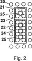
図2は、公知の組立玩具セットから組み立てられた組立要素の概略図である。
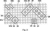
図3は、本発明の組立玩具セットの概略図である。
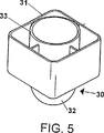
図4および図5は、公知の組立玩具要素をそれぞれ上面および底面から見た斜視図である。
図6は、別の公知の組立玩具要素の上面斜視図である。
図7は、本発明による組立玩具セットにおいて用いられる新規な組立玩具要素を底面から見た部分斜視図である。
図8は、図7に示す組立玩具要素の底面図である。
図9および図10は、本発明による玩具組立セットにおいて用いられる別の新規な組立玩具要素をそれぞれ上面および底面から見た斜視図である。
図11は、図1と同じタイプの結合スタッドを有する組立玩具要素に接続したときの図7および図8の組立要素の概略図である。
図12は、図4、図5、図7および図8に示す組立要素に他の公知の組立要素を組み合わせた本発明の組立セットの概略図である。
図13は、図7および図8と同様の2つの組立要素を有する図10に示す組立セットの概略図である。
図1は、円筒形の結合スタッド10の公知の配置を示す、結合スタッド10は組立プレート等の不図示の組立要素の外面上に、相互に垂直な4×5の主方向列として配置される。図1に示す組立セットはDUPLO(R)組立セットである。この組立セットでは、2つの主方向の結合スタッド列間に同一のすき間が設けられるため、スタッドが方形のパターンを形成する。DUPLO(R)組立玩具要素11は、結合スタッド列間のすき間に主方向に配置される結合壁12を有し、該結合壁の内側は結合スタッド10の2つの列に接している。組立要素11には、結合壁12によって構成される中空部内に結合手段として結合管13が設けられ、この結合管が4つの結合スタッド10に接することによってこれと結合する。
図1に示す方形パターンの結合スタッドはさらに、主方向に対して45度の相対角を成す対角方向列をも形成する。対角方向列間には幅dの空間がある。
図2は、円筒形の結合スタッド20の別の公知の配置を示し、この場合は結合スタッドは組立プレート等の図示してない組立要素の外面に、相互に直角をなす主方向列を含んで4×8列に配置される。図2に示す組立セットはLEGO SYSTEM(R)組立セットである。この組立セットにおいても、2つの主方向の結合スタッド間に設けらる等しい空間で方形のパターンが形成される。図1と同様に、2つの組立要素21および22が図2の結合スタッド20に固定される。組立要素21および22は、結合スタッド間の空間に主方向にそれぞれの結合壁23および24を置き、かつ結合スタッド20に接するように配置される。組立要素21および22のそれぞれの結合壁によって構成される中空部には、米国特許第3,005,282に記載の管状結合手段または結合管25が設けられている。結合管25は4つの結合スタッド20に接し、結合管の内径は結合スタッド20の外形に一致する。
図4および図5は公知の組立玩具の要素30を示すが、これはWO 96/09869に記載され、かつ商標PRIMO(R)により販売されている組立玩具システムの一部を構成するものである。組立要素30は、水平断面が実質的に正方形であって角を丸めた箱形の基部を有する。組立要素30には4つの外郭壁31があり、該要素の上面に結合スタッド32が設けられている。結合スタッド32の底部には短い円筒形状部分が設けられ、その頂部は円筒形状部分と同じ径の半球状形である。組立要素の外郭壁31は該要素底部に中空部を構成し、この中空部内に結合スタッド32に合う内径を有する円筒形の結合管から成る結合手段33が設けられる。それによって結合スタッド32を結合管33内に受けることができる。結合スタッド32および結合管33の径は、幼児がブロックを積み重ねるのに適した組立要素となるよう摩擦を著しく無くすか、あるいは一定の保持力を有するように摩擦を付けるかによって相互接続が可能になっている。結合管33の最下部は組立要素の外郭壁31の下方のある一定の距離まで延びている。
図6は別の組立玩具要素35を示し、図4および図5の要素30と同様にWO 96/09869に開示された組立玩具システムの一部となるものである。要素35には、要素30の結合スタッド32とそれぞれ同一の4つの結合スタッド32が設けられ、要素35ではこれら4つの結合スタッドが方形に配置される。要素35の下側には、4つの結合スタッドの下にそれぞれ管状の結合スカート(図示せず)が要素30と同じように設けられている。
図7および図8は、新規な玩具組立要素40を示す。結合スカート40の底部から外側結合スカート41および内側結合スカート42が下向きに突出する。この結合スカート41および42により、組立要素40は、図4および図5の要素30あるいは図6の要素35のように、WO 96/09869に開示の組立システムの組立要素と組み合わせることができる。要素30の単一の結合スタッド32は、摩擦付きまたは摩擦無しに、外側結合スカート41および内側結合スカート42間の図示した四箇所32aでそれぞれに受けることができ、さらに内側結合スカート42内の図示した一箇所32bで受けることができる。さらに、要素35の4つの結合スタッド32は、摩擦付きまたは摩擦無しで四箇所32aで受けることができる。
図11は、玩具組立要素40がDUPLO(R)組立要素を示す。この場合の該組立要素はDUPLO(R)結合スタッド10付きの組立プレートとも組合せ可能である。外側結合スカート41は、5×5の方形内結合スタッド10を跨ぐかまたは取り囲み、スカートの内側は方形のコーナーにある4つの結合スタッド10aおよび方形側部中央の4つのスタッド10bに接する。したがって、外側結合スカート41は結合スタッド列間の主方向に配置されることになる。内側結合スカート42は、2つの交差する主方向列に位置する5つの結合スタッド10を跨ぐかまたは取り囲む。この場合、内側結合スカートは結合スタッド列間の対角方向に配置されることになる。
図9および図10は、新規な組立玩具要素50を示し、図4および図5の組立要素30と同様に、4つの外郭壁51と結合スタッドとを有し、断面がほぼ方形で角が丸められた箱形の基部である。組立要素50が図4および図5の組立要素30と実質唯一異なるところは、外郭壁51によって構成される中空部内に図7、図8および図11の組立要素の内側結合スカート42と同寸法の結合スカート52が設けられることである。組立要素50は、DUPLO(R)組立スタッド10を有する他の組立要素と、組立スカート52が組立スタッド10の対角列間のすき間に配置された状態で相互接続することができる。
図12は、DUPLO(R)組立スタッド10付きの組立プレートに固定された2つのDUPLO(R)組立要素11および1つのPRIMO(R)組立要素30を示す。PRIMO(R)組立要素30は、その結合スカート33が4つの結合スタッド10を取り囲み、組立要素はその近辺に自由な回転を制約する要素が無ければ、WO 96/09869において教示されるように、前記4つのスタッドのまわりに回転することができる。PRIMO(R)組立要素30は、DUPLO(R)組立要素に完全な突合わせ状態で積み重ねることはできず、またその外郭壁31はDUPLO(R)要素の外郭壁に整合させることはできない。これは、PRIMO(R)要素の外郭壁とDUPLO(R)要素の外郭壁との間隔が2つの隣り合う結合スタッド10間の間隔のちょうど半分であり、かつこの間隔がDUPLO(R)要素およびPRIMO(R)要素とも結合スタッド10上を移動できる最小間隔だからである。
図12はまた、PRIMO(R)組立要素30に実質的に突合わせ配置された新規な組立要素50をも示す。これにおいては、組立要素50の結合スカート52が4つの結合スタッド10を取り囲み、結合スカート52の直立部または壁が結合スタッド10の対角列間のすき間に配置される。したがって新規な組立要素50は、PRIMO(R)要素の位置にちょうど一致する結合スタッド10の位置に配置される。しかし、新規な組立要素50は、DUPLO(R)組立スタッド10に積み重なった位置では回転できない。
組立要素40の結合スカート42と同様に、結合スカート52は他の組立要素のPRIMO(R)結合スタッド32にも積み重ね可能である。したがって、回転ができない点は別として、新規な組立要素50は公知のPRIMO(R)組立要素30と同じ組立部品として使用可能である。回転ができないのは、結合スカートの直立結合壁が結合スタッドの対角列間の空間に配置されるからである。
図13は、DUPLO(R)組立スタッド10付きの組立プレートに固定された2つの新規な組立要素50および2つのDUPLO(R)組立要素11を示す。これにおいては、組立要素50はその結合スカート52が図11の結合スカート42と同様に5つの結合スタッド10を取り囲むように配置される。組立要素50は、外郭壁51が主方向に配され、かつDUPLO(R)組立要素11とほぼ突き合わせ状態に配置される。さらに、DUPLO(R)組立要素11と新規な組立要素50とは、外郭壁同士が一列に並んで組立プレートに対してほぼ垂直な同一面上にある。
したがって、結合スタッドの対角列間に配置される壁を備えた新規な結合スカート42または52を有するこの組立要素は、公知のPRIMO(R)要素とまったく同じ結合位置と、さらにまた対角線方向の隣り合う結合スタッド間の中間の位置に新たな結合位置とを有する。それによって、結合可能位置の場合の数が倍増する。
図3は、本発明の組立玩具システムの別の実施形態を示す。これにおいては、結合スタッド20が直角をなす主方向の列に配置された公知のLEGO SYSTEM(R)組立プレートが使用される。図1と同様に、結合スタッド20の対角列間に空間(図示せず)が設けられる。ここには、4つの結合スタッド20を取り囲みかつこの4つの結合スタッド20に接する結合管25を有する公知の組立要素21を示す。
さらに図3は、玩具組立要素60a、60b、61a、61b、62aおよび62bを示し、これらはすべて結合スタッド20の対角列間のすき間に配置された結合壁を有する。組立要素60aおよび60bは同一物であるが、それぞれに1つおよび2つの結合スタッド20を取り囲む2つの異なる結合位置にある状態を示す。さらに、要素61aおよび61bは同一物であるが、それぞれに4個および5個の結合スタッド20を取り囲む2つの結合位置にある状態を示す。また、要素62aおよび62bもまた同一物であるが、それぞれに10個および11個の結合スタッド20を取り囲んでいる。
組立要素21および22と同様に、組立要素61a、61b、62aおよび62bはその結合壁によって画定される空所内に円筒形の結合管25を有する。これらの結合管25は図示したような2つの結合状態を有する。なぜならば、結合管はその外側が図2のように4つの結合スタッド20に結合するか、あるいはその内側が単一の結合スタッド20の周囲に結合するか、いずれかであるからである。
組立要素50と同様に、組立要素60a、60b、61a、61b、62aおよび62bは、主方向に外郭壁を設けるか、あるいは対角線方向に外郭壁を設けるかすることができ、それによってこれらの壁は相互にほぼ近接して積むことができる。
組立要素50、60a、60b、61a、61b、62aおよび62bは、その結合壁間に差が常に1となる偶数個または奇数個の結合スタッド20を包含することが出来る。The present invention relates to an assembled toy set or an assembly system having mutually connectable assembly elements. Specifically, this assembly element is an element comprising a coupling stud on one side and a pair of parallel coupling walls having a coupling means for detachably receiving the coupling stud of another assembly element on the other side and constituting a hollow portion. is there.
An assembly toy system of this kind is known in particular from US Pat. No. 3,0052,822, characterized in that the coupling studs are arranged in a main direction perpendicular to each other, thereby forming a square pattern. An assembly element having a pair of parallel coupling walls is provided so that the coupling walls can be arranged in the gaps between the coupling stud rows. This coupling wall is generally the outer wall of the assembly element. In the pattern of such a rectangular coupling studs also form diagonal directions column between the main direction column, the assembly set sold by trademark LEGO (R) or DUPLO (R), in the diagonal direction row A space wider than zero is provided in between.
DE 2414246 teaches an assembly element having studs on rows perpendicular to each other. Large and small studs arranged alternately in each main row also form diagonal rows. The diameter of the large and small studs and the relative spacing of the studs is such that the two parallel walls of the assembly block with the wall forming the hollow under the assembly block are either on the main row of large studs or diagonally. Any one of the small studs can be arranged arbitrarily.
U.S. Pat. No. 3,162,973 shows an assembled toy block having outer walls that are at right angles to each other and forming a hollow under the assembly block. This void has a wall extending diagonally. However, the assembly block can only interconnect the outer walls in the main direction of the stud.
The assembled toy set according to the invention further provides an assembly element having coupling walls arranged in diagonal rows so as to be located in the spaces between the diagonal rows of coupling studs. This makes a new assembly option available.
Hereinafter, the present invention will be described in more detail with reference to the drawings.
FIG. 1 is a schematic cross-sectional view of a prior art toy assembly element in which coupling studs are arranged perpendicular to each other.
FIG. 2 is a schematic view of assembly elements assembled from a known assembled toy set.
FIG. 3 is a schematic view of the assembled toy set of the present invention.
4 and 5 are perspective views of a known assembled toy element as seen from the top and bottom, respectively.
FIG. 6 is a top perspective view of another known assembled toy element.
FIG. 7 is a partial perspective view of a new assembled toy element used in the assembled toy set according to the present invention as seen from the bottom.
FIG. 8 is a bottom view of the assembled toy element shown in FIG.
9 and 10 are perspective views of another novel assembled toy element used in the toy assembly set according to the present invention as seen from the top and bottom, respectively.
11 is a schematic view of the assembly element of FIGS. 7 and 8 when connected to an assembly toy element having a coupling stud of the same type as FIG.
FIG. 12 is a schematic view of the assembly set of the present invention in which the assembly elements shown in FIGS. 4, 5, 7 and 8 are combined with other known assembly elements.
13 is a schematic view of the assembly set shown in FIG. 10 having two assembly elements similar to FIGS. 7 and 8. FIG.
FIG. 1 shows a known arrangement of
The rectangular pattern of connecting studs shown in FIG. 1 also forms a diagonal row with a relative angle of 45 degrees with respect to the main direction. There is a space of width d between the diagonal rows.
FIG. 2 shows another known arrangement of
Although FIGS. 4 and 5 show an
FIG. 6 shows another assembled
7 and 8 show a new
Figure 11 is a
FIGS. 9 and 10 show a new assembled
Figure 12 shows a DUPLO (R) assembled
Figure 12 also illustrates a
Like the
Figure 13 shows a DUPLO (R) assembled
Thus, the building element having a novel
FIG. 3 shows another embodiment of the assembled toy system of the present invention. In this known LEGO SYSTEM (R) assembled
Further, FIG. 3 shows
Similar to the
Similar to the
The
Claims (3)
該第1タイプ組立要素と相互に結合し、矩形の断面の中空部を画定する二対の平行な結合壁(12,23,24)と摩擦により取外し可能な係合で該第1タイプ組立要素の該連結スタッド(10,20)を受容するための結合手段(13,25)とを有する第2タイプ結合要素(11,21,22)であって、該平行な結合壁は該結合スタッドの列間の主方向に配置され、該結合壁は2つの第2タイプの結合要素の各々の一の結合壁を同時に隣り合う該連結スタッド間に入れることができる厚さを有する第2タイプ結合要素(11,21,22)と、
該第1タイプ組立要素上の少なくとも2つの結合スタッドを受容するための矩形断面を有する中空部を画定する二対の平行な結合壁を有する第3タイプ組立要素(40,50,60a,60b,61a,61b,62a,62b)であって、該第3タイプ組立要素の結合壁(42,52)は結合スタッド(10,20)の対角列間に該対角方向に配置され(40,50,60a,60b,61a,61b,62a,62b)、隣り合う対角列間の幅(d)に対応した厚さを有する該第3タイプ組立要素とを備えることを特徴とする玩具組立てセット。A first type assembly element having uniform connecting studs (10, 20) arranged in a two-dimensional periodic pattern in two main directions perpendicular to each other, the connecting studs comprising: A first type assembly element that also forms diagonal rows diagonally with respect to the main direction, whereby a width (d) of 0 or more is secured between the adjacent diagonal rows;
The first type assembly element with frictionally removable engagement with two pairs of parallel coupling walls (12, 23, 24) interconnecting with the first type assembly element and defining a rectangular cross-section cavity. A second coupling element (11, 21, 22) having coupling means (13, 25) for receiving the coupling stud (10, 20) of the coupling stud, A second type coupling element which is arranged in a main direction between the rows and has a thickness such that one coupling wall of each of the two second type coupling elements can be inserted between adjacent coupling studs simultaneously (11, 21, 22),
A third type assembly element (40, 50, 60a, 60b, having two pairs of parallel connection walls defining a hollow portion having a rectangular cross section for receiving at least two connection studs on the first type assembly element; 61a, 61b, 62a, 62b), wherein the coupling walls (42, 52) of the third type assembly element are disposed diagonally between diagonal rows of coupling studs (10, 20) (40, 50, 60a, 60b, 61a, 61b, 62a, 62b) and a third type assembly element having a thickness corresponding to the width (d) between adjacent diagonal rows. .
Applications Claiming Priority (3)
| Application Number | Priority Date | Filing Date | Title |
|---|---|---|---|
| DK1007/96 | 1996-09-17 | ||
| DK100796A DK100796A (en) | 1996-09-17 | 1996-09-17 | A toy |
| PCT/DK1997/000387 WO1998011968A1 (en) | 1996-09-17 | 1997-09-16 | A toy building set |
Publications (3)
| Publication Number | Publication Date |
|---|---|
| JP2001500412A JP2001500412A (en) | 2001-01-16 |
| JP2001500412A5 JP2001500412A5 (en) | 2005-05-12 |
| JP3727951B2 true JP3727951B2 (en) | 2005-12-21 |
Family
ID=8099960
Family Applications (1)
| Application Number | Title | Priority Date | Filing Date |
|---|---|---|---|
| JP51419498A Expired - Fee Related JP3727951B2 (en) | 1996-09-17 | 1997-09-16 | Assembly toy set |
Country Status (16)
| Country | Link |
|---|---|
| US (1) | US6102766A (en) |
| EP (1) | EP1011836B8 (en) |
| JP (1) | JP3727951B2 (en) |
| CN (1) | CN1108179C (en) |
| AT (1) | ATE242028T1 (en) |
| AU (1) | AU719644B2 (en) |
| CA (1) | CA2266001C (en) |
| CZ (1) | CZ91699A3 (en) |
| DE (1) | DE69722672T2 (en) |
| DK (2) | DK100796A (en) |
| ES (1) | ES2200194T3 (en) |
| PL (1) | PL186215B1 (en) |
| PT (1) | PT1011836E (en) |
| TW (1) | TW328526B (en) |
| WO (1) | WO1998011968A1 (en) |
| ZA (1) | ZA978329B (en) |
Families Citing this family (35)
| Publication number | Priority date | Publication date | Assignee | Title |
|---|---|---|---|---|
| TW443939B (en) * | 1999-08-27 | 2001-07-01 | Interlego Ag | A toy building set |
| DK174659B1 (en) * | 2000-01-11 | 2003-08-18 | Lego As | Toy building element with transverse openings |
| US6447360B1 (en) * | 2000-04-26 | 2002-09-10 | Soren Christian Sorensen | Interconnection of toy building elements in a releasable restraining engagement |
| US6560934B1 (en) * | 2002-04-15 | 2003-05-13 | Deslauriers, Inc. | Snappable shim assembly |
| JP3927069B2 (en) * | 2002-05-08 | 2007-06-06 | 株式会社コナミデジタルエンタテインメント | Assembly element toy set, assembly element |
| US20040108433A1 (en) * | 2002-12-10 | 2004-06-10 | Tonya Gunsch | Ergonomic mouse pad support |
| US7140944B2 (en) * | 2005-01-24 | 2006-11-28 | Mattel, Inc. | Connecting toy |
| WO2006094364A1 (en) * | 2005-03-10 | 2006-09-14 | Robert Alexander | Viral diagnostic method and well for use in same |
| US20060254162A1 (en) * | 2005-04-21 | 2006-11-16 | Deslauriers, Inc. | Shim having through openings |
| US20090017716A1 (en) * | 2007-07-11 | 2009-01-15 | Michael Marzetta | Construction system |
| US7841923B2 (en) * | 2007-11-13 | 2010-11-30 | Minds-I, Inc. | Vehicle axle joint for a toy vehicle |
| DK2249933T3 (en) * | 2008-02-05 | 2013-06-17 | Lego As | gaming dice |
| DE102008012515A1 (en) * | 2008-03-04 | 2009-10-01 | Quantum Verlag Gmbh | Method for depicting facts or for producing a 2- or 3-dimensional mapping |
| JP5154294B2 (en) | 2008-05-02 | 2013-02-27 | Ykk株式会社 | Slide fastener |
| TW201026369A (en) * | 2009-01-13 | 2010-07-16 | Weistech Technology Co Ltd | A toy brick structure |
| JP2010172568A (en) * | 2009-01-30 | 2010-08-12 | Kawada Co Ltd | Block toy |
| US8742814B2 (en) | 2009-07-15 | 2014-06-03 | Yehuda Binder | Sequentially operated modules |
| US8602833B2 (en) | 2009-08-06 | 2013-12-10 | May Patents Ltd. | Puzzle with conductive path |
| US8205406B2 (en) * | 2010-05-28 | 2012-06-26 | Arxx Corporation | Wall clip and shim adapted for insulating concrete walls and similar materials |
| CN102878160B (en) * | 2011-07-14 | 2015-09-02 | 台湾百和工业股份有限公司 | Mechanical surface bonding fastener |
| US9019718B2 (en) | 2011-08-26 | 2015-04-28 | Littlebits Electronics Inc. | Modular electronic building systems with magnetic interconnections and methods of using the same |
| US9597607B2 (en) | 2011-08-26 | 2017-03-21 | Littlebits Electronics Inc. | Modular electronic building systems with magnetic interconnections and methods of using the same |
| US11330714B2 (en) | 2011-08-26 | 2022-05-10 | Sphero, Inc. | Modular electronic building systems with magnetic interconnections and methods of using the same |
| EP2766180A4 (en) | 2011-10-14 | 2015-08-12 | Staklite Ip Llc | Panel with core layer and method |
| US9345981B1 (en) * | 2014-02-24 | 2016-05-24 | Hasbro, Inc. | Multidimensional alignment spacing for toy building elements |
| PT3140019T (en) * | 2014-05-09 | 2020-09-11 | Slab Dream Lab Llc | Custom multi-colored images applied to three dimensional products, such as polystyrene, post production on an individual basis |
| CZ28122U1 (en) * | 2015-02-23 | 2015-04-20 | Kosáčci - Hračky, Které Letííí, S.R.O. | Educational game and/or building blocks |
| DE202015002996U1 (en) * | 2015-04-21 | 2015-06-22 | Joachim Peiler | Flat connectable game building blocks |
| USD834106S1 (en) * | 2016-07-12 | 2018-11-20 | Mega Brands Inc. | Construction set element |
| DK179581B1 (en) * | 2016-09-06 | 2019-02-20 | Noclav Design Aps | A toy-building element |
| TWM542507U (en) * | 2017-01-12 | 2017-06-01 | Mentari Massen International Co Ltd | Castle building blocks |
| CN106955495A (en) * | 2017-04-10 | 2017-07-18 | 上海葡萄纬度科技有限公司 | A kind of various dimensions, can the block toy building set freely built of positive and negative |
| JP7414591B2 (en) * | 2019-02-01 | 2024-01-16 | 株式会社バンダイ | Building toy sets and building elements for building toy sets |
| US11616844B2 (en) | 2019-03-14 | 2023-03-28 | Sphero, Inc. | Modular electronic and digital building systems and methods of using the same |
| USD977027S1 (en) * | 2020-05-27 | 2023-01-31 | Mattel-Mega Holdings (Us), Llc | Construction set element |
Family Cites Families (10)
| Publication number | Priority date | Publication date | Assignee | Title |
|---|---|---|---|---|
| US3162973A (en) * | 1961-06-27 | 1964-12-29 | Interlego Ag | Toy building element |
| US3005282A (en) * | 1958-01-28 | 1961-10-24 | Interlego Ag | Toy building brick |
| DE1202198B (en) * | 1960-11-11 | 1965-09-30 | Berco Lux Nv | Toy building element |
| DK120627C (en) * | 1967-11-29 | 1971-12-06 | Lego System As | Toy building set. |
| DE2414246A1 (en) * | 1974-03-25 | 1975-10-16 | Roland Dipl Ing Zahn | Plug pin baseplate for toy building blocks - has pins of alternating dias in rectangular array |
| FI67751C (en) * | 1981-07-22 | 1985-05-10 | Partek Ab | PAO MINERALULL BASERAD ISOLATIONSKROPP OCH FOERFARANDE FOER FRMSTAELLNING DAERAV |
| JPS58143243A (en) * | 1982-02-19 | 1983-08-25 | Minolta Camera Co Ltd | Measuring apparatus for coloring matter in blood without taking out blood |
| DK170833B1 (en) * | 1993-09-22 | 1996-02-05 | Lego As | Toy building kits and building elements therefor |
| DK172406B1 (en) * | 1993-09-22 | 1998-05-25 | Lego As | Building element for a construction building set |
| DK112094A (en) * | 1994-09-29 | 1996-03-30 | Lego As | Stacking block system |
-
1996
- 1996-09-17 DK DK100796A patent/DK100796A/en not_active Application Discontinuation
- 1996-09-17 TW TW085111360A patent/TW328526B/en active
-
1997
- 1997-09-16 AT AT97939984T patent/ATE242028T1/en not_active IP Right Cessation
- 1997-09-16 US US09/254,815 patent/US6102766A/en not_active Expired - Fee Related
- 1997-09-16 DE DE69722672T patent/DE69722672T2/en not_active Expired - Fee Related
- 1997-09-16 WO PCT/DK1997/000387 patent/WO1998011968A1/en active IP Right Grant
- 1997-09-16 ES ES97939984T patent/ES2200194T3/en not_active Expired - Lifetime
- 1997-09-16 CA CA002266001A patent/CA2266001C/en not_active Expired - Fee Related
- 1997-09-16 EP EP97939984A patent/EP1011836B8/en not_active Expired - Lifetime
- 1997-09-16 CN CN97198016A patent/CN1108179C/en not_active Expired - Fee Related
- 1997-09-16 AU AU42002/97A patent/AU719644B2/en not_active Ceased
- 1997-09-16 JP JP51419498A patent/JP3727951B2/en not_active Expired - Fee Related
- 1997-09-16 DK DK97939984T patent/DK1011836T3/en active
- 1997-09-16 CZ CZ99916A patent/CZ91699A3/en unknown
- 1997-09-16 PT PT97939984T patent/PT1011836E/en unknown
- 1997-09-16 ZA ZA9708329A patent/ZA978329B/en unknown
- 1997-09-16 PL PL97332280A patent/PL186215B1/en not_active IP Right Cessation
Also Published As
| Publication number | Publication date |
|---|---|
| ATE242028T1 (en) | 2003-06-15 |
| EP1011836A1 (en) | 2000-06-28 |
| JP2001500412A (en) | 2001-01-16 |
| PL332280A1 (en) | 1999-08-30 |
| ES2200194T3 (en) | 2004-03-01 |
| PT1011836E (en) | 2003-10-31 |
| EP1011836B1 (en) | 2003-06-04 |
| DK1011836T3 (en) | 2003-09-29 |
| ZA978329B (en) | 1998-03-24 |
| TW328526B (en) | 1998-03-21 |
| CN1108179C (en) | 2003-05-14 |
| DK100796A (en) | 1998-03-18 |
| CN1230897A (en) | 1999-10-06 |
| AU4200297A (en) | 1998-04-14 |
| DE69722672D1 (en) | 2003-07-10 |
| WO1998011968A1 (en) | 1998-03-26 |
| CZ91699A3 (en) | 1999-08-11 |
| PL186215B1 (en) | 2003-11-28 |
| EP1011836B8 (en) | 2004-03-03 |
| CA2266001C (en) | 2005-05-17 |
| CA2266001A1 (en) | 1998-03-26 |
| US6102766A (en) | 2000-08-15 |
| AU719644B2 (en) | 2000-05-11 |
| DE69722672T2 (en) | 2003-12-04 |
Similar Documents
| Publication | Publication Date | Title |
|---|---|---|
| JP3727951B2 (en) | Assembly toy set | |
| EP0121433B1 (en) | Interconnectible polygonal construction modules | |
| AU672926B2 (en) | A toy building set and building elements therefor | |
| US6702640B1 (en) | Block toy | |
| US6554676B1 (en) | Toy building set | |
| US3603026A (en) | Fabricating toys | |
| US10737191B2 (en) | Assembly unit for toy assembly block | |
| US20160263489A1 (en) | Multidimensional alignment spacing for toy building elements | |
| EP3305387A1 (en) | Dove-shaped building block | |
| US20200222821A1 (en) | Cube Based Building Block System | |
| US20020098774A1 (en) | Geometric construction system | |
| US9737826B2 (en) | Pairing block set and toy block thereof | |
| US3405479A (en) | Toy building block | |
| JP4537397B2 (en) | Building materials for building modular foundation structures | |
| JP6674569B1 (en) | Assembly toy sets and assembly elements for assembly toy sets | |
| RU2468848C1 (en) | Toy construction set element (versions) | |
| JP3195386U (en) | Block toys | |
| KR20170142421A (en) | Figure game apparatus and method thereof | |
| KR100537395B1 (en) | A toy building set | |
| KR200158851Y1 (en) | A fabricated toy utilizing block | |
| JPH0438869Y2 (en) | ||
| TWM634645U (en) | Building Blocks | |
| WO2014054962A1 (en) | Construction kit element (alternatives) | |
| CZ294739B6 (en) | Building blocks system |
Legal Events
| Date | Code | Title | Description |
|---|---|---|---|
| A521 | Request for written amendment filed |
Free format text: JAPANESE INTERMEDIATE CODE: A523 Effective date: 20040915 |
|
| A621 | Written request for application examination |
Free format text: JAPANESE INTERMEDIATE CODE: A621 Effective date: 20040915 |
|
| TRDD | Decision of grant or rejection written | ||
| A01 | Written decision to grant a patent or to grant a registration (utility model) |
Free format text: JAPANESE INTERMEDIATE CODE: A01 Effective date: 20050906 |
|
| A61 | First payment of annual fees (during grant procedure) |
Free format text: JAPANESE INTERMEDIATE CODE: A61 Effective date: 20050930 |
|
| R150 | Certificate of patent or registration of utility model |
Free format text: JAPANESE INTERMEDIATE CODE: R150 |
|
| LAPS | Cancellation because of no payment of annual fees |