JP3727923B2 - Space block deflector for increased cooling of generator coil ends. - Google Patents
Space block deflector for increased cooling of generator coil ends. Download PDFInfo
- Publication number
- JP3727923B2 JP3727923B2 JP2002552170A JP2002552170A JP3727923B2 JP 3727923 B2 JP3727923 B2 JP 3727923B2 JP 2002552170 A JP2002552170 A JP 2002552170A JP 2002552170 A JP2002552170 A JP 2002552170A JP 3727923 B2 JP3727923 B2 JP 3727923B2
- Authority
- JP
- Japan
- Prior art keywords
- cavity
- rotor
- dynamoelectric machine
- flow
- space block
- Prior art date
- Legal status (The legal status is an assumption and is not a legal conclusion. Google has not performed a legal analysis and makes no representation as to the accuracy of the status listed.)
- Expired - Fee Related
Links
Images


Classifications
-
- H—ELECTRICITY
- H02—GENERATION; CONVERSION OR DISTRIBUTION OF ELECTRIC POWER
- H02K—DYNAMO-ELECTRIC MACHINES
- H02K3/00—Details of windings
- H02K3/04—Windings characterised by the conductor shape, form or construction, e.g. with bar conductors
- H02K3/24—Windings characterised by the conductor shape, form or construction, e.g. with bar conductors with channels or ducts for cooling medium between the conductors
-
- H—ELECTRICITY
- H02—GENERATION; CONVERSION OR DISTRIBUTION OF ELECTRIC POWER
- H02K—DYNAMO-ELECTRIC MACHINES
- H02K9/00—Arrangements for cooling or ventilating
- H02K9/08—Arrangements for cooling or ventilating by gaseous cooling medium circulating wholly within the machine casing
Description
【0001】
【発明の属する技術分野】
本発明は、通常冷却媒体が不足する空洞の中央部に向けて、より多くの冷却媒体を分配することにより、発電機ロータの冷却を向上させるための構造に関する。
【0002】
【発明の背景】
大型ターボ発電機のような発電電動機械の出力定格は、導電体の絶縁に必要な温度限界の故に、一定量を超える電流をロータ界磁巻線に供給できる能力によってしばしば制限される。従って、ロータ巻線の効果的冷却は、その機械の出力能力に直接貢献する。このことは、これらの機械の典型的な構造故に直接的な強制冷却が難しく、コスト高になるロータ端部領域において特に言えることである。現今の市場傾向は、低コストでより高い効率と信頼性とを有しかつより高い出力密度を有する発電機を必要としているから、ロータ端部領域の冷却が限定要因となっている。
【0003】
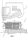
ターボ発電機ロータは、典型的にはロータのスロット内に取り付けられた同心の矩形コイルで構成される。ロータ本体による支持を超えるコイル末端部分(一般にコイル端と呼ばれる)は、典型的には保持リングにより回転力に抗して支持される(図1参照)。相対的位置を維持し、かつ熱負荷のような軸方向負荷に対する機械的安定性を加えるために、同心のコイル端の間には支持ブロックが断続的に置かれる(図2参照)。更に、銅コイルは、それらの外径において、遠心力に抗する保持リングにより半径方向に拘束される。スペースブロックと保持リングとの存在は、銅コイルに曝される多数の冷却媒体領域を生じる。主要な冷却媒体通路は、スピンドルとコイル端底部との間の軸方向通路である。また、コイルの境界面と、ブロックと、保持リング構造の内表面とによりコイルの間には、互いに分離された空洞が形成される。コイル端は、回転力によりコイル端の半径方向下方からこれらの空洞内へ送り込まれる冷却媒体に曝される(図3参照)。この熱伝達は低くなりがちである。その理由は、コンピュータを用いた流体力学的分析により算出された回転する単一のコイル端空洞内における流跡線によれば、冷却媒体流は、空洞に入り、主循環を横切り、空洞から流出するからである。通常この循環は、特に空洞の中心部付近において熱伝達係数が低くなる。従って、これはコイル端における熱除去のための手段ではあるが、能率は比較的良好でない。
【0004】
より多くの冷却ガスをロータ端部領域内に流すために、様々な方式が使用されてきた。これらの冷却方式は全て、(1)導電体内に溝を機械加工するか、あるいは通路を形成することにより、銅製導電体内に直接冷却通路を作って、次に機械のどこか他の領域へガスを圧送すること、及び/又は(2)冷却ガスを導電体の表面上に強制的に流すために、バッフル、流路、及びポンプ要素を付け加えて、比較的高圧及び低圧の領域を作り出すことに依存している。
【0005】
一部のシステムにおいては、冷却ガスをロータコイル端に沿って直接圧送しエアギャップ内に排出可能にするために、高度に応力が加わる保持リングに半径方向の孔を貫通させているが、このようなシステムは、保持リングに加わる大きな機械的応力及びその疲労寿命を考慮した場合、限られた有用性しか持つことができない。
【0006】
従来の強制的ロータ端部冷却方式が使用される場合には、ロータの構造が著しく複雑となりコストが高くなる。例えば、直接冷却される導電体は、冷却通路を形成するために機械加工されるか、あるいは冷却通路が形成されるように製造されなくてはならない。これに加えて、ロータ内のいずれかの場所でガスを排出させるために、出口マニフォルドが設けられなくてはならない。強制冷却方式は、ロータ端部領域が別々の圧力区域に分割されることを必要とし、これに加えて多数のバッフル、流路、及びポンプ要素をも必要とし、この場合もこれらが複雑さとコストを増大させる。
【0007】
これらの強制又は直接冷却方式が使用されない場合には、ロータコイル端は受動的に冷却される。受動冷却は、同心のロータ巻線間に形成されるブラインドの行止り空洞内でガスを循環させるために、ロータの遠心力と回転力とに依存する。ロータコイル端の受動冷却は、時として「自由対流」冷却とも呼ばれる。
【0008】
受動冷却は、直接及び強制冷却を行う能動的システムと比較すると、熱除去能力は低下するが、複雑さとコストが最少化されるという利点をもたらす。典型的な空洞の4つの「側壁」は、同心の導電体とこれらの導電体を隔てる絶縁ブロックとによって形成され、「底」壁(半径方向外側の)は、回転に抗してコイル端を支える保持リングによって形成されるというように、これらの空洞はいずれにしても周囲を囲われているから、同心のロータ巻線間の空洞内へ入る全ての冷却ガスは、流入したのと同じ開口を通って出て行かなくてはならない。冷却ガスは、導電体とロータスピンドルとの間の環状の空間から入る。従って熱除去は、空洞内におけるガスの低い循環速度と、これらの空間に出入りできるガスの限られた量とによって制限される。
【0009】
典型的構成においては、端部領域内の冷却ガスは、ロータ速度に達するほどにはまだ十分に加速されていない、つまり冷却ガスはロータ速度の何割かの速度で回転している。ロータと流体との間の相対的速度による衝突によって、流体が空洞内へ送り込まれるので、流れ方向で言えば下流であり、流体が高い運動量で流入し、しかも流体冷却媒体が最も低温であるスペースブロック付近において、熱伝達係数は一般的に最高になる。熱伝達係数はまた、一般的に空洞周縁付近でも高い。空洞の中心部は、冷却される度合いが最も低い。
【0010】
受動冷却システムの熱除去能力を増大させることは、低コストで単純かつ高信頼性の構造という利点を保ちながら、ロータの許容電流能力を増大させ、発電機の定格能力を増大させることになる。
【0011】
参考文献としてその開示内容が本明細書に組み込まれている米国特許第5,644,179号は、自然発生するフローセル内に追加的な冷却流を、フローセルと同一方向に直接導入することにより、大きな単一のフロー循環セルの流速を増させて、熱伝達を増大させるための方法を記載している。これは図4及び図5に示されている。この方法は、循環セルの強さを増強することにより、空洞内における熱伝達を増大させるが、それでもなおロータ空洞の中央領域は低速度のままであり、従って低熱伝達のまま取り残される。隅部領域にも同じ低熱伝達がまだ存続する。
【0012】
【発明の概要】
本発明は、同心のロータコイル端と支持ブロックとによりそれらの間に形成される空洞の中央部に向けて、冷却媒体流を向けることにより、発電機ロータの冷却を向上させるための構造と方法とに関する。
【0013】
本発明の例示的な実施形態においては、流れを向け直すために、少なくとも1つのデフレクタが、空洞の下流側に配置されたスペースブロックの表面上に取り付けられて、冷却媒体流を空洞の中央部に向けて分配し直す。更に具体的に言えば、本発明は、それぞれの空洞内の流れを、通常流れが不足している空洞中央部に向けて分配し直して、回転するアセンブリにおける熱伝達性能を大いに増大させるために、少なくとも1つのデフレクタ構造体を発電機ロータコイル端アセンブリ内の少なくとも1つのスペースブロックの下流表面上に設ける。
【0014】
1つの実施形態においては、スペースブロックの半径方向内側部分に到達し及び/又は該内側部分に沿って流れる冷却媒体流のかなり大きな部分を遮断するために、デフレクタは、関連するスペースブロックからほぼ軸方向へ延びる。遮断された流れは、空洞中央部に向けて向け直される。デフレクタ構造体の半径方向外側のスペースブロックに対してほぼ直接的に流れる冷却媒体流は、そのほぼ通常の円形状流れ経路に沿って流れ続けることになる。
【0015】
本発明の別の実施形態によれば、デフレクタ構造体は、空洞の深さ即ち空洞の軸方向寸法の一部分だけに延びる。このことは、大きな運動量を有する冷却媒体の或る部分を、空洞の半径方向外側の隅部に到達させ、冷却媒体の残りの部分を空洞中央部に向けて方向付けることを可能にする。部分深さのデフレクタ構造体は、空洞の隣接する1つのコイル端壁から、あるいは空洞の隣接する他のコイル端壁から、あるいは関連するスペースブロックのほぼ中央部から空洞深さの一部分だけに延びるように配置することができる。この実施形態においては、デフレクタは、関連するスペースブロックの深さの約半分だけに延びる。
【0016】
本発明の更に別の実施形態によれば、各々が空洞の軸方向寸法即ち空洞の深さの一部分だけに延びる、2つ又はそれ以上の軸方向に整列されたデフレクタ構造体が設けられる。このことは、大きな運動量を有する冷却媒体の或る部分を、軸方向に隣り合うデフレクタ構造体の間を通って空洞の半径方向外側の隅部に到達させ、冷却媒体の残りの部分を空洞の中央部に向けて方向付けることを可能にする。
【0017】
【発明の実施の形態】
本発明の上記及びその他の目的並びに利点は、添付図面と関連してなされる本発明の現在好ましいとされる例示的な実施形態に関する以下の一層詳細な説明を注意深く検討することによって、より完全に理解され、その真価が認められるであろう。
【0018】
図面において種々の図を通して同一参照符号は同じ要素を示しているが、その図面を参照すると、図1及び図2は、ガス冷却式発電電動機械のためのロータ10を示しており、この発電電動機械はまた、ロータを取り囲むステータ12を含む。ロータは、ロータスピンドル16上にこれを中心にして置かれ、軸方向に対向する端面を有するほぼ円筒形の本体部分14を含み、図1には、これら2つの端面のうちの1つの端面の一部分18が示されている。本体部分には、ロータ巻線を構成する同心に配設されたコイル22を受けるための、円周方向に間隔を置いて配置された複数の軸方向に延びるスロット20が設けられる。解り易くするために、ロータコイルが5つだけ図示されているが、実用に際しては通常もっと多くのロータコイルが使用される。
【0019】
具体的に言うと、ロータ巻線の一部を構成する多数の導電体バー24が、個々のスロット内で積み重ねられる。隣り合う導電体バーは、電気絶縁層26によって隔てられる。積み重ねられる導電体バーは、銅などの導電性材料で作られ、典型的にはウェッジ26(図1)によりスロット内に保持される。本体部分の対向する各端部において、導電体バー24は末端巻線27により相互に接続され、末端巻線は、端面を超えて軸方向に延び、積み重ねられたコイル端28を形成する。末端巻線も電気絶縁層によって互いに隔てられる。
【0020】
特に図1を参照すると、遠心力に抗してコイル端を定位置に保持するために、本体部分の各端部における末端巻線の周りには、保持リング30が置かれる。保持リングは、その1つの端部において本体部分に固定され、ロータスピンドル16を覆って延びる。保持リング30の遠位端には、中心リング32が取り付けられる。当技術分野では知られているように、保持リング30と中心リング32とは、上記とは異なるやり方で取り付けることも可能であることに注目されたい。ガス入口通路34を形成するために、中心リング32の内周縁部はロータスピンドル16から半径方向に間隔を置いて配置され、また環状の領域36を形成するために、コイル端28はスピンドル16から間隔を置いて配置される。冷却ガスをコイル22へ送給するために、スロット20に沿って形成された多数の軸方向冷却通路38は、環状領域36を介してガス入口通路34と流体連通している。
【0021】
次に図2を参照すると、ロータ10の各端部におけるコイル端28は、多数のスペーサ又はスペースブロック40により、円周方向と軸方向とに隔てられる。(図示を明瞭にするために、図1にスペースブロックは示されていない。)スペースブロックは、隣り合うコイル端28の間の空間内に置かれた、絶縁材料からなる細長いブロックであり、コイル端の半径方向の深さ全体を超えて環状空隙36内まで延びる。従って、末端巻線27の同心の積み重ねの間の空間は、幾つかの空洞に分割される。図3に示すように、これらの空洞は、その頂部を保持リング30により、また四方を隣接するコイル端28とスペースブロック40とにより境界づけられる。図1において最もよく分るように、これらの空洞の各々は、環状領域36を介してガス入口通路34と流体連通している。従って、ガス入口通路34を介して、コイル端28とロータスピンドル16との間の環状領域36に入る冷却ガスの一部は、空洞42に入り、その内部で循環し、次いでコイル端とロータスピンドルとの間の環状領域36に戻る。図1及び図3には、空気流が矢印で示されている。
【0022】
回転する発電機空洞内で作用する固有のポンプ作用と回転力とは、図3に概略的に示したように、大きな単一のフロー循環セルを生み出す。このフロー循環セルは、空洞の周縁付近で最高速度を示すが、空洞の中央領域における固有の低速度により、中央領域は十分に冷却されないままである。図3から分るように、フローセルの円形運動は冷却流を隅部内に運ばないから、隅部領域の大きな区域も十分には冷却されない。
【0023】
次に図6を参照すると、ここには矢印Xで表した回転方向を有する空洞142のうちの幾つかを示すロータコイル端アセンブリの一部分が図示されている。本発明の実施形態によれば、冷却媒体流をそれぞれの空洞142の中央部に分配し直して、該部分の熱伝達率を増大させるために、少なくとも1つ、好ましくは各々のスペースブロック140は、それぞれの空洞142の下流側に位置するスペースブロックの表面146(以下においては下流表面と呼ぶ)上にデフレクタ構造体144を備えている。各デフレクタ構造体144は、矢印Aで示すように、流れを遮断し該流れを向け直すための、全体的に湾曲した下表面148を有する。不必要な圧力損失なしに流れを効果的に遮断するためにデフレクタが全体的に流れに面する薄い縁部152を形成するように、上表面150は全体的に平坦である。
【0024】
作動時に、X方向へのロータの回転は、冷却ガスをガス入口34(図1)を介してコイル端28とロータスピンドル16との間の環状領域36内へ引き込ませる。動圧ヘッドが発生して、該動圧ヘッドが冷却ガスを空洞142の下流側146に向けてほぼ円形状の流れで送り込む。しかしながら、図6に図示した実施形態においては、冷却媒体流のうちの少なくとも一部分はデフレクタ144により遮断されて、デフレクタが存在しなければ普通冷却媒体流が不足する筈の冷却空洞142の中央領域に向けて、矢印Aで示すように向け直される。デフレクタによって遮断されない冷却媒体流は、矢印Bで示すように、そのほぼ円形状の流れを続ける。遮断された流れと遮断されなかった流れとは、空洞の上流側で再び合体して、図示した構成においては、時計方向へスペースブロック140の下方に流れ続け、そして次の空洞内へ流入する。この実施形態においては、空洞の深さ即ち軸方向寸法のかなり大きな部分、例えば空洞深さの少なくとも約75%、更に好ましくは100%ほどにわたって延びている単一の流れデフレクタが設けられる。
【0025】
次に図7を参照すると、ここには本発明の第2の実施形態が示されている。更に具体的に言えば、図7は、スペースブロック240の間に形成され、矢印Xで表す回転方向を有する空洞242を示すロータコイル端の一部分を示す。図示したように、隣接する空洞の中央領域へ冷却媒体流を反らすために、少なくとも1つのデフレクタ構造体244が設けられる。図6の実施形態におけるのと同様に、図示したアセンブリにおいては、デフレクタ構造体244は、少なくとも1つのスペースブロック240の下流表面246上に設けられる。しかしながら、この実施形態においては、大きな運動量を有する循環冷却媒体流の一部分を空洞の半径方向外側の隅部に到達させために、少なくとも1つの垂直流れ領域を残し、同時に冷却媒体の残りの部分は、空洞の中央に向けて反らされるように、各デフレクタ244は、スペースブロックの深さの一部分、即ち軸方向寸法の一部分だけに延びる。
【0026】
この実施形態によれば、部分深さのデフレクタ構造体は、空洞の隣接する1つのコイル端壁から、あるいは空洞の隣接する他のコイル端壁から、あるいは関連するスペースブロックのほぼ中央部から空洞深さの一部分だけに延びるように配置することができる。例示的な実施形態においては、関連するスペースブロックの深さの約半分だけに延びる単一のデフレクタ244が設けられる。また、図7の概略図によって表している別の実施形態によれば、軸方向に整列させた2つ又はそれ以上のデフレクタ構造体が設けられ、各デフレクタ構造体は、空洞の軸方向寸法又は深さの一部分だけに延びる。このようにして、少なくとも1つの垂直流れ領域が、大きな運動量を有する循環冷却媒体流を空洞の半径方向外側の隅部に到達させるために確保され、他方冷却媒体の残りの部分は、空洞の中央部に反らされる。
【0027】
従って、図示するように、それぞれの空洞242内への冷却媒体流は、スペースブロックの表面246に向かって流れ、また、スペースブロックの表面246に沿って半径方向外向きに流れ始めることになる。流れの一部分は、デフレクタ構造体244によって遮断されて、矢印Aで示すように、該デフレクタ構造体244によってそれぞれの空洞の中央領域に向けて反らされる。冷却媒体流の残りの部分は、截頭デフレクタ構造体の軸方向の長さによって形成される空隙の故に、デフレクタ構造体をバイパスし、矢印Cで示すように、上方へ又スペースブロックに沿って半径方向外向きに流れ続け、矢印Bによって示すように循環流として流れ続ける。反らされた流れと反らされなかった流れとは、空洞の上流側で再び合体して、図示した実施形態においては、次の空洞242に向かってスペースブロック240の下方及び周りを時計方向へ流れ続ける。
【0028】
現在のところ好ましい実施形態においては、単に表面乱流を引き起こすだけでなく、流れを効果的に遮断して、該流れを空洞の中央領域に向けて向け直すために、デフレクタ144、244は、冷却空洞の円周方向寸法の少なくとも約20%、更に好ましくは少なくとも約25%の長さだけ延びる。デフレクタの下表面148、248の湾曲形状が、デフレクタ機能を向上させる。
【0029】
本発明を、現在最も実用的で好ましいと考えられる実施形態に関連させて説明してきたが、本発明はここに開示した実施形態に限定されるものではなく、逆に、添付の特許請求の範囲の技術思想及び技術的範囲内に含まれる様々な変更及び等価な構成を保護することを意図していることを理解されたい。
【図面の簡単な説明】
【図1】 ロータと向かい合うステータを備える発電電動機械ロータのコイル端領域の一部分の断面図。
【図2】 図1の線2−2に沿って見た、発電電動機械ロータの平面断面図。
【図3】 コイル端空洞に入り、これを通過する受動ガス流を示す概略図。
【図4】 米国特許第5,644,179号に開示された発明の第1の実施形態によるロータコイル端領域の一部分の一部切り欠き斜視図。
【図5】 米国特許第5,644,179号に開示された発明の第2の実施形態を示すロータコイル端領域の一部分の一部切り欠き斜視図。
【図6】 冷却媒体を、通常冷却媒体が不足する空洞の中央部へ反らすためにスペースブロックの下流側に設けられた、本発明の一実施形態としてのデフレクタを示す断面図。
【図7】 冷却媒体の一部分を空洞中央部へ反らせながら、冷却媒体のうちの或る部分を空洞の半径方向外側領域へ容易に流すことを可能にするために、各々が空洞の深さの一部分だけに延びるようにした少なくとも1つのデフレクタが設けられた、本発明の別の実施形態を示す図。
【符号の説明】
10 ロータ
12 ステータ
14 本体部分
16 ロータスピンドル
18 本体部分の1つの端部
22 コイル
24 導電体バー
26 ウェッジ
27 末端巻線
28 コイル端
30 保持リング
32 中心リング
34 ガス入口通路
36 環状領域
38 軸方向冷却通路[0001]
BACKGROUND OF THE INVENTION
The present invention relates to a structure for improving cooling of a generator rotor by distributing a larger amount of cooling medium toward a central portion of a cavity that normally lacks the cooling medium.
[0002]
BACKGROUND OF THE INVENTION
The power rating of a dynamoelectric machine, such as a large turbogenerator, is often limited by the ability to supply more than a certain amount of current to the rotor field windings due to the temperature limits required for conductor insulation. Thus, effective cooling of the rotor windings directly contributes to the output capability of the machine. This is especially true in the rotor end region where direct forced cooling is difficult and costly due to the typical construction of these machines. Current market trends require generators with lower costs, higher efficiency and reliability, and higher power density, so cooling the rotor end region is a limiting factor.
[0003]
Turbogenerator rotors are typically composed of concentric rectangular coils mounted in the rotor slots. The coil end portion beyond the support by the rotor body (commonly referred to as the coil end) is typically supported against the rotational force by a retaining ring (see FIG. 1). Support blocks are intermittently placed between concentric coil ends to maintain relative position and add mechanical stability to axial loads such as thermal loads (see FIG. 2). Furthermore, the copper coils are radially constrained at their outer diameter by a retaining ring that resists centrifugal forces. The presence of the space block and retaining ring creates a number of cooling medium areas that are exposed to the copper coil. The main coolant passage is the axial passage between the spindle and the coil end bottom. In addition, cavities separated from each other are formed between the coils by the boundary surface of the coil, the block, and the inner surface of the retaining ring structure. The coil ends are exposed to a cooling medium fed into these cavities from below the coil ends in the radial direction by rotational force (see FIG. 3). This heat transfer tends to be low. The reason is that according to the trajectory line in a rotating single coil end cavity calculated by computer hydrodynamic analysis, the coolant flow enters the cavity, traverses the main circulation and exits the cavity. Because it does. Usually, this circulation has a low heat transfer coefficient, especially near the center of the cavity. Thus, this is a means for heat removal at the coil ends, but the efficiency is relatively poor.
[0004]
Various schemes have been used to flow more cooling gas into the rotor end region. All of these cooling schemes (1) create a cooling passage directly in the copper conductor by machining grooves or forming passages in the conductor and then gas to somewhere else in the machine And / or (2) adding baffles, flow paths, and pump elements to create a relatively high pressure and low pressure region to force the cooling gas to flow over the surface of the conductor. It depends.
[0005]
In some systems, a radial hole is inserted through the highly stressed retaining ring to allow the cooling gas to be pumped directly along the rotor coil end and out into the air gap. Such a system can have only limited utility when considering the large mechanical stresses on the retaining ring and its fatigue life.
[0006]
When the conventional forced rotor end cooling method is used, the rotor structure is significantly complicated and the cost is increased. For example, a conductor that is directly cooled must be machined to form a cooling passage or manufactured to form a cooling passage. In addition to this, an outlet manifold must be provided in order to discharge gas anywhere in the rotor. The forced cooling scheme requires that the rotor end region be divided into separate pressure zones, plus a number of baffles, flow paths, and pump elements, which again are complex and costly. Increase.
[0007]
If these forced or direct cooling schemes are not used, the rotor coil ends are passively cooled. Passive cooling relies on the rotor's centrifugal and rotational forces to circulate gas in blind blind cavities formed between concentric rotor windings. Passive cooling of the rotor coil ends is sometimes referred to as “free convection” cooling.
[0008]
Passive cooling offers the advantage of reduced complexity and cost, but reduced heat removal capability compared to active systems with direct and forced cooling. The four “side walls” of a typical cavity are formed by concentric conductors and an insulating block that separates these conductors, and the “bottom” walls (radially outward) provide coil ends against rotation. Since these cavities are surrounded in any case, as formed by the supporting retaining ring, all the cooling gas entering the cavities between the concentric rotor windings is the same opening as it entered. You have to go out through. The cooling gas enters from an annular space between the conductor and the rotor spindle. Heat removal is therefore limited by the low circulation rate of the gas in the cavity and the limited amount of gas that can enter and exit these spaces.
[0009]
In a typical configuration, the cooling gas in the end region is not yet accelerated enough to reach the rotor speed, i.e., the cooling gas is rotating at a fraction of the rotor speed. A space where the fluid is pumped into the cavity by a collision due to the relative velocity between the rotor and the fluid, so that it is downstream in the flow direction, the fluid flows in with a high momentum, and the fluid cooling medium is the coldest. Near the block, the heat transfer coefficient is typically highest. The heat transfer coefficient is also generally high near the cavity periphery. The central part of the cavity is least cooled.
[0010]
Increasing the heat removal capability of a passive cooling system will increase the allowable current capability of the rotor and increase the rated capability of the generator while retaining the advantages of a low cost, simple and reliable structure.
[0011]
US Pat. No. 5,644,179, whose disclosure is incorporated herein by reference, directly introduces an additional cooling flow into the naturally occurring flow cell in the same direction as the flow cell, A method for increasing the flow rate of a large single flow circulation cell to increase heat transfer is described. This is illustrated in FIGS. This method increases the heat transfer in the cavity by increasing the strength of the circulation cell, yet the central region of the rotor cavity remains at a low speed and thus remains low heat transfer. The same low heat transfer still exists in the corner area.
[0012]
SUMMARY OF THE INVENTION
The present invention is a structure and method for improving cooling of a generator rotor by directing a coolant flow toward a central portion of a cavity formed therebetween by concentric rotor coil ends and a support block. And about.
[0013]
In an exemplary embodiment of the invention, to redirect the flow, at least one deflector is mounted on the surface of a space block located downstream of the cavity to direct the coolant flow to the center of the cavity. Redistribute to. More specifically, the present invention redistributes the flow in each cavity towards the center of the cavity where normal flow is lacking to greatly increase heat transfer performance in rotating assemblies. , Providing at least one deflector structure on a downstream surface of at least one space block in the generator rotor coil end assembly.
[0014]
In one embodiment, in order to block a significant portion of the coolant flow that reaches the radial inner portion of the space block and / or flows along the inner portion, the deflector is substantially axial from the associated space block. Extend in the direction. The blocked flow is redirected toward the center of the cavity. The coolant flow that flows almost directly to the radially outer space block of the deflector structure will continue to flow along its generally normal circular flow path.
[0015]
According to another embodiment of the invention, the deflector structure extends only a portion of the cavity depth, ie the axial dimension of the cavity. This allows a part of the cooling medium with a large momentum to reach the radially outer corner of the cavity and direct the remaining part of the cooling medium towards the center of the cavity. The partial depth deflector structure extends from one adjacent coil end wall of the cavity, or from another adjacent coil end wall of the cavity, or from approximately the center of the associated space block to only a portion of the cavity depth. Can be arranged as follows. In this embodiment, the deflector extends only about half the depth of the associated space block.
[0016]
In accordance with yet another embodiment of the present invention, two or more axially aligned deflector structures are provided, each extending only a portion of the axial dimension of the cavity or the depth of the cavity. This causes a portion of the cooling medium having a large momentum to pass between the axially adjacent deflector structures to reach the radially outer corner of the cavity, while the remaining portion of the cooling medium is allowed to enter the cavity. It can be oriented toward the center.
[0017]
DETAILED DESCRIPTION OF THE INVENTION
The above and other objects and advantages of the present invention will be more fully understood by careful consideration of the following more detailed description of the presently preferred exemplary embodiments of the invention made in conjunction with the accompanying drawings, in which: It will be understood and its true value will be recognized.
[0018]
In the drawings, like reference numerals designate like elements throughout the various views. Referring to the drawings, FIGS. 1 and 2 show a
[0019]
Specifically, a number of conductor bars 24 that form part of the rotor winding are stacked in individual slots. Adjacent conductor bars are separated by an electrically insulating layer 26. The stacked conductor bars are made of a conductive material such as copper and are typically held in the slots by wedges 26 (FIG. 1). At opposite ends of the body portion, the conductor bars 24 are connected to each other by a terminal winding 27 that extends axially beyond the end face to form a stacked
[0020]
With particular reference to FIG. 1, retaining rings 30 are placed around the distal windings at each end of the body portion to hold the coil ends in place against centrifugal forces. The retaining ring is secured to the body portion at one end thereof and extends over the
[0021]
Referring now to FIG. 2, the coil ends 28 at each end of the
[0022]
The inherent pumping action and rotational force acting within the rotating generator cavity creates a large single flow circulation cell, as shown schematically in FIG. This flow circulation cell exhibits the highest speed near the cavity periphery, but the central region remains uncooled due to the inherent low speed in the central region of the cavity. As can be seen from FIG. 3, the circular motion of the flow cell does not carry the cooling flow into the corner, so that a large area of the corner area is not sufficiently cooled.
[0023]
Referring now to FIG. 6, there is illustrated a portion of a rotor coil end assembly showing some of the
[0024]
In operation, rotation of the rotor in the X direction causes cooling gas to be drawn into the
[0025]
Referring now to FIG. 7, there is shown a second embodiment of the present invention. More specifically, FIG. 7 shows a portion of the rotor coil end that shows a
[0026]
According to this embodiment, the partial depth deflector structure can be formed from one adjacent coil end wall of the cavity, from another adjacent coil end wall of the cavity, or from approximately the center of the associated space block. It can be arranged to extend only part of the depth. In the exemplary embodiment, a
[0027]
Thus, as shown, the coolant flow into each
[0028]
In the presently preferred embodiment, the
[0029]
Although the present invention has been described in connection with the embodiments that are presently considered to be most practical and preferred, the invention is not limited to the embodiments disclosed herein and, conversely, the appended claims. It should be understood that various changes and equivalent arrangements included within the spirit and scope of the invention are intended to be protected.
[Brief description of the drawings]
FIG. 1 is a cross-sectional view of a part of a coil end region of a dynamoelectric machine rotor including a stator facing the rotor.
FIG. 2 is a plan sectional view of the generator motor rotor as viewed along line 2-2 in FIG.
FIG. 3 is a schematic diagram showing passive gas flow entering and passing through a coil end cavity.
FIG. 4 is a partially cutaway perspective view of a portion of a rotor coil end region according to a first embodiment of the invention disclosed in US Pat. No. 5,644,179.
FIG. 5 is a partially cutaway perspective view of a portion of a rotor coil end region showing a second embodiment of the invention disclosed in US Pat. No. 5,644,179.
FIG. 6 is a cross-sectional view showing a deflector according to an embodiment of the present invention, which is provided on the downstream side of a space block in order to warp the cooling medium to the central portion of the cavity where the cooling medium is usually insufficient.
FIG. 7 shows that each of the depths of the cavities is designed to allow a portion of the cooling medium to flow easily to the radially outer region of the cavity while deflecting a portion of the cooling medium to the center of the cavity. FIG. 5 shows another embodiment of the present invention provided with at least one deflector that extends only partially.
[Explanation of symbols]
10 Rotor 12
Claims (11)
隣り合う前記コイル端の間に置かれ、それらの間に空洞を形成する少なくとも1つのスペースブロックと、
前記空洞内で循環する冷却媒体流を遮断し、該循環する冷却媒体流を前記空洞の中央領域へ向け直すために、前記スペースブロックの空洞に面する表面上に設けられた少なくとも1つの流れデフレクタ構造体と、
を含むことを特徴とする冷却式発電電動機械。A rotor having a body portion, an axially extending coil, and a terminal winding forming a plurality of axially extending coil ends beyond at least one end of the body portion;
At least one space block placed between adjacent coil ends and forming a cavity therebetween;
At least one flow deflector provided on the surface of the space block facing the cavity to block the coolant flow circulating in the cavity and redirect the circulating coolant stream to a central region of the cavity A structure,
A cooling type generator-motor machine comprising:
前記本体部分上に置かれた軸方向に延びるコイルと、前記本体部分の少なくとも1つの端部を超えて軸方向に延びる、互いに間隔を置いて配置された同心のコイル端とを含み、該コイル端と前記スピンドルとがそれらの間に環状空間を形成している、ロータ巻線と、
前記コイル端の隣り合うコイル端の間に配置され、それによって複数の空洞を形成する複数のスペースブロックと、
を含み、
前記空洞の各々が、隣接するスペースブロックと隣接するコイル端とによって境界づけられ、前記環状空間に対して開放されており、
少なくとも1つの流れデフレクタ構造体が、循環する冷却媒体流を遮断し、該循環する冷却媒体流を前記それぞれの空洞の中央領域へ向け直すために、少なくとも1つの前記スペースブロックの空洞に面する表面上に設けられている、
ことを特徴とする冷却式発電電動機械。A rotor having a spindle and a body portion;
An axially extending coil disposed on the body portion and concentric coil ends spaced apart from each other extending axially beyond at least one end of the body portion, the coil A rotor winding, wherein the end and the spindle form an annular space between them;
A plurality of space blocks disposed between adjacent coil ends of the coil ends, thereby forming a plurality of cavities;
Including
Each of the cavities is bounded by an adjacent space block and an adjacent coil end and is open to the annular space;
A surface facing the cavity of at least one of the space blocks, wherein at least one flow deflector structure blocks the circulating coolant stream and redirects the circulating coolant stream to the central region of the respective cavity Provided above,
A cooling-type dynamoelectric machine characterized by that.
Applications Claiming Priority (2)
| Application Number | Priority Date | Filing Date | Title |
|---|---|---|---|
| US09/739,359 US6465917B2 (en) | 2000-12-19 | 2000-12-19 | Spaceblock deflector for increased electric generator endwinding cooling |
| PCT/US2001/045299 WO2002050982A2 (en) | 2000-12-19 | 2001-11-30 | Spaceblock deflector for increased electric generator endwinding cooling |
Publications (3)
| Publication Number | Publication Date |
|---|---|
| JP2004516789A JP2004516789A (en) | 2004-06-03 |
| JP2004516789A5 JP2004516789A5 (en) | 2005-01-20 |
| JP3727923B2 true JP3727923B2 (en) | 2005-12-21 |
Family
ID=24971919
Family Applications (1)
| Application Number | Title | Priority Date | Filing Date |
|---|---|---|---|
| JP2002552170A Expired - Fee Related JP3727923B2 (en) | 2000-12-19 | 2001-11-30 | Space block deflector for increased cooling of generator coil ends. |
Country Status (12)
| Country | Link |
|---|---|
| US (1) | US6465917B2 (en) |
| EP (1) | EP1346457B1 (en) |
| JP (1) | JP3727923B2 (en) |
| KR (1) | KR100467388B1 (en) |
| CN (1) | CN100352142C (en) |
| AU (1) | AU2002239423A1 (en) |
| CA (1) | CA2399347C (en) |
| CZ (1) | CZ303848B6 (en) |
| DE (1) | DE60115494T2 (en) |
| ES (1) | ES2250506T3 (en) |
| MX (1) | MXPA02008084A (en) |
| WO (1) | WO2002050982A2 (en) |
Families Citing this family (16)
| Publication number | Priority date | Publication date | Assignee | Title |
|---|---|---|---|---|
| US6720687B2 (en) * | 2000-12-22 | 2004-04-13 | General Electric Company | Wake reduction structure for enhancing cavity flow in generator rotor endwindings |
| US6617749B2 (en) * | 2000-12-22 | 2003-09-09 | General Electric Company | Re-entrant spaceblock configuration for enhancing cavity flow in rotor endwinding of electric power generator |
| US20020079753A1 (en) * | 2000-12-22 | 2002-06-27 | Turnbull Wayne Nigel Owen | High thermal conductivity spaceblocks for increased electric generator rotor endwinding cooling |
| US6759770B1 (en) * | 2003-04-11 | 2004-07-06 | General Electric Company | Cooling system for modular field windings of a generator |
| US7009317B2 (en) * | 2004-01-14 | 2006-03-07 | Caterpillar Inc. | Cooling system for an electric motor |
| DE502004012011D1 (en) * | 2004-10-28 | 2011-01-27 | Siemens Ag | ELECTROPLATE WITH DISTANCE STRIPS AND CORRESPONDING MANUFACTURING METHOD |
| US7342345B2 (en) * | 2005-10-28 | 2008-03-11 | General Electric Company | Paddled rotor spaceblocks |
| US7541714B2 (en) * | 2006-04-05 | 2009-06-02 | General Electric Company | Streamlined body wedge blocks and method for enhanced cooling of generator rotor |
| US7763996B2 (en) * | 2006-08-28 | 2010-07-27 | General Electric Company | Method and apparatus for cooling generators |
| US8198762B2 (en) | 2008-01-31 | 2012-06-12 | Pratt & Whitney Canada Corp. | Winding end turn cooling in an electric machine |
| US8115352B2 (en) * | 2009-03-17 | 2012-02-14 | General Electric Company | Dynamoelectric machine coil spacerblock having flow deflecting channel in coil facing surface thereof |
| JP2010263778A (en) | 2009-04-28 | 2010-11-18 | General Electric Co <Ge> | Dynamoelectric machine coil spaceblock having flow deflecting structure in coil facing surface thereof |
| US8525376B2 (en) * | 2010-10-01 | 2013-09-03 | General Electric Company | Dynamoelectric machine coil spaceblock having flow deflecting structure in coil facing surface thereof |
| JP6165340B2 (en) * | 2014-07-25 | 2017-07-19 | 三菱電機株式会社 | Rotating electric machine |
| EP4106152A1 (en) | 2021-06-17 | 2022-12-21 | General Electric Company | Magnetic mass for a rotor, associated rotor and rotating electric machine |
| EP3961871A3 (en) | 2021-09-01 | 2022-04-06 | General Electric Technology GmbH | A system for supporting turns of generator rotor endwinding coils and a method for winding and rewinding of a power generator for a fossil or a nuclear power plant |
Family Cites Families (13)
| Publication number | Priority date | Publication date | Assignee | Title |
|---|---|---|---|---|
| US2778959A (en) * | 1953-07-22 | 1957-01-22 | Vickers Electrical Co Ltd | Dynamo electric machine cooling |
| US2844746A (en) * | 1956-02-17 | 1958-07-22 | Gen Electric | Support means for rotor end windings of dynamoelectric machines |
| US2904708A (en) * | 1957-12-18 | 1959-09-15 | Gen Electric | Ventilation of end turn portions of generator rotor winding |
| JPS5778350A (en) * | 1980-10-31 | 1982-05-17 | Hitachi Ltd | Rotor in rotary electric machine |
| JPS5778338A (en) * | 1980-11-04 | 1982-05-17 | Hitachi Ltd | Cooling device of rotor endcoil part of rotary electric machine |
| FR2565741B1 (en) * | 1984-06-07 | 1995-01-13 | Alsthom Atlantique | DEVICE FOR DISTRIBUTING A COOLING GAS AT A FREETHED END OF THE ROTOR EXCITATION WINDING OF A TURBO-ALTERNATOR |
| US5652469A (en) * | 1994-06-16 | 1997-07-29 | General Electric Company | Reverse flow ventilation system with stator core center discharge duct and/or end region cooling system |
| US5644179A (en) | 1994-12-19 | 1997-07-01 | General Electric Company | Gas cooled end turns for dynamoelectric machine rotor |
| JPH11146587A (en) * | 1997-11-04 | 1999-05-28 | Toshiba Corp | Rotor of electric rotary machine |
| JP2000350412A (en) * | 1999-06-02 | 2000-12-15 | Hitachi Ltd | Dynamo-electric machine |
| US6339268B1 (en) * | 2000-02-02 | 2002-01-15 | General Electric Company | Cooling ventilation circuit for rotor end winding and slot end region cooling |
| US6252318B1 (en) * | 2000-02-09 | 2001-06-26 | General Electric Co. | Direct gas cooled longitudinal/cross-flow rotor endwinding ventillation scheme for rotating machines with concentric coil rotors |
| US6204580B1 (en) * | 2000-02-09 | 2001-03-20 | General Electric Co. | Direct gas cooled rotor endwinding ventilation schemes for rotating machines with concentric coil rotors |
-
2000
- 2000-12-19 US US09/739,359 patent/US6465917B2/en not_active Expired - Fee Related
-
2001
- 2001-11-30 ES ES01987183T patent/ES2250506T3/en not_active Expired - Lifetime
- 2001-11-30 KR KR10-2002-7010647A patent/KR100467388B1/en not_active IP Right Cessation
- 2001-11-30 DE DE60115494T patent/DE60115494T2/en not_active Expired - Lifetime
- 2001-11-30 EP EP01987183A patent/EP1346457B1/en not_active Expired - Lifetime
- 2001-11-30 JP JP2002552170A patent/JP3727923B2/en not_active Expired - Fee Related
- 2001-11-30 CN CNB01805272XA patent/CN100352142C/en not_active Expired - Fee Related
- 2001-11-30 MX MXPA02008084A patent/MXPA02008084A/en active IP Right Grant
- 2001-11-30 CA CA002399347A patent/CA2399347C/en not_active Expired - Fee Related
- 2001-11-30 AU AU2002239423A patent/AU2002239423A1/en not_active Abandoned
- 2001-11-30 WO PCT/US2001/045299 patent/WO2002050982A2/en active IP Right Grant
- 2001-11-30 CZ CZ20022716A patent/CZ303848B6/en not_active IP Right Cessation
Also Published As
| Publication number | Publication date |
|---|---|
| WO2002050982A2 (en) | 2002-06-27 |
| CZ20022716A3 (en) | 2003-01-15 |
| EP1346457A2 (en) | 2003-09-24 |
| CA2399347A1 (en) | 2002-06-27 |
| EP1346457B1 (en) | 2005-11-30 |
| US6465917B2 (en) | 2002-10-15 |
| KR100467388B1 (en) | 2005-01-24 |
| KR20020077462A (en) | 2002-10-11 |
| US20020074869A1 (en) | 2002-06-20 |
| DE60115494T2 (en) | 2006-08-03 |
| DE60115494D1 (en) | 2006-01-05 |
| JP2004516789A (en) | 2004-06-03 |
| CZ303848B6 (en) | 2013-05-29 |
| AU2002239423A1 (en) | 2002-07-01 |
| WO2002050982A3 (en) | 2003-02-20 |
| CA2399347C (en) | 2005-08-02 |
| ES2250506T3 (en) | 2006-04-16 |
| CN100352142C (en) | 2007-11-28 |
| MXPA02008084A (en) | 2003-02-27 |
| CN1636307A (en) | 2005-07-06 |
Similar Documents
| Publication | Publication Date | Title |
|---|---|---|
| JP3721361B2 (en) | Improved cooling of generator coil ends | |
| JP3727923B2 (en) | Space block deflector for increased cooling of generator coil ends. | |
| JP3737481B2 (en) | Flow-through space block with deflector and method for improving generator coil end cooling | |
| KR101248277B1 (en) | Paddled rotor spaceblocks | |
| JP3737480B2 (en) | Space block scoop to enhance heat transfer in rotor cavity | |
| JP3737479B2 (en) | Gas cooling type coil end and coil end cooling method for generator motor rotor | |
| JP3727924B2 (en) | Wake reduction structure to enhance cavity flow at coil end of generator rotor | |
| US6617749B2 (en) | Re-entrant spaceblock configuration for enhancing cavity flow in rotor endwinding of electric power generator |
Legal Events
| Date | Code | Title | Description |
|---|---|---|---|
| A131 | Notification of reasons for refusal |
Free format text: JAPANESE INTERMEDIATE CODE: A131 Effective date: 20050531 |
|
| TRDD | Decision of grant or rejection written | ||
| A01 | Written decision to grant a patent or to grant a registration (utility model) |
Free format text: JAPANESE INTERMEDIATE CODE: A01 Effective date: 20050906 |
|
| A61 | First payment of annual fees (during grant procedure) |
Free format text: JAPANESE INTERMEDIATE CODE: A61 Effective date: 20050929 |
|
| R150 | Certificate of patent or registration of utility model |
Free format text: JAPANESE INTERMEDIATE CODE: R150 |
|
| FPAY | Renewal fee payment (event date is renewal date of database) |
Free format text: PAYMENT UNTIL: 20091007 Year of fee payment: 4 |
|
| FPAY | Renewal fee payment (event date is renewal date of database) |
Free format text: PAYMENT UNTIL: 20091007 Year of fee payment: 4 |
|
| FPAY | Renewal fee payment (event date is renewal date of database) |
Free format text: PAYMENT UNTIL: 20101007 Year of fee payment: 5 |
|
| FPAY | Renewal fee payment (event date is renewal date of database) |
Free format text: PAYMENT UNTIL: 20111007 Year of fee payment: 6 |
|
| FPAY | Renewal fee payment (event date is renewal date of database) |
Free format text: PAYMENT UNTIL: 20121007 Year of fee payment: 7 |
|
| FPAY | Renewal fee payment (event date is renewal date of database) |
Free format text: PAYMENT UNTIL: 20131007 Year of fee payment: 8 |
|
| R250 | Receipt of annual fees |
Free format text: JAPANESE INTERMEDIATE CODE: R250 |
|
| LAPS | Cancellation because of no payment of annual fees |