JP3727770B2 - Color image reader - Google Patents
Color image reader Download PDFInfo
- Publication number
- JP3727770B2 JP3727770B2 JP31357397A JP31357397A JP3727770B2 JP 3727770 B2 JP3727770 B2 JP 3727770B2 JP 31357397 A JP31357397 A JP 31357397A JP 31357397 A JP31357397 A JP 31357397A JP 3727770 B2 JP3727770 B2 JP 3727770B2
- Authority
- JP
- Japan
- Prior art keywords
- line
- image
- color
- color separation
- document
- Prior art date
- Legal status (The legal status is an assumption and is not a legal conclusion. Google has not performed a legal analysis and makes no representation as to the accuracy of the status listed.)
- Expired - Fee Related
Links
Images


Landscapes
- Facsimile Scanning Arrangements (AREA)
- Editing Of Facsimile Originals (AREA)
- Facsimile Image Signal Circuits (AREA)
Description
【0001】
【発明の属する技術分野】
本発明は、原稿画像を色分解して読み取るカラー画像読み取り装置に関し、特に原稿の種類を判定するカラー画像読み取り装置に関する。
【0002】
【従来の技術】
従来、この種のカラー画像読み取り装置としては例えば
(A)特公昭5−83142号公報
(B)特開平2−168769号公報
(C)特開平9−465533号公報
が知られている。
【0003】
ところで、従来例(A)にも記載されているように、原稿の種類(正確には原稿に使用されている色材)によっては、人間の目には同一の色に見えても異なる色として読み取られることが知られている。そこで、原稿の種類を検出するために、従来例(A)では通常の3原色のセンサとは別のセンサを設け、従来例(B)では3原色の各々に対して2つの異なる感度ピークを有するセンサを設け、従来例(C)では面順次に異なる色分解特性で原稿を読み取る方法が提案されている。
【0004】
【発明が解決しようとする課題】
しかしながら、従来例(A)及び(B)では原稿の種類を検出するために、通常の3原色のセンサとは別のセンサを設けるので、この別のセンサに付随する回路等を考慮すると、装置の構成が複雑になるという問題点がある。また、従来例(C)では別のセンサを設けないので上記問題点を解決することができるが、色分解特性が面順次で異なるので、原稿の種類を検出するためには少なくとも2回の予備的な読み取りを必要とし、このため読み取り処理の即時性に欠けるという問題点がある。
【0005】
また、他の方法(D)として、原稿をライン単位で異なる色分解特性で読み取り、同一ラインを同時に色分解する方法が考えられるが、この方法(D)では同一ラインを同時に色分解する必要があるので、特殊な色分解系(ダイクロイックプリズム)が必要になるという問題点がある。
【0006】
本発明は上記従来の問題点に鑑み、原稿の種類を判定する場合に一般的な3ラインイメージセンサのみを使用し、また、予備的な読み取りを不要にすることができるカラー画像読み取り装置を提供することを目的とする。
【0007】
本発明はまた、一般的な3ラインイメージセンサのみを使用して簡単な構成でライン単位で異なる色分解特性で読み取ることができるカラー画像読み取り装置を提供することを目的とする。
【0008】
【課題を解決するための手段】
第1の手段は上記目的を達成するために、3つのラインイメージセンサを副走査方向にずらして配置した3ライン型カラーイメージセンサによって原稿画像を色分解して読み取るカラー画像読み取り装置において、前記イメージセンサが原稿を読み取る際の色分解特性をライン単位で切り換える色分解特性切り換え手段と、前記イメージセンサが出力する各ラインの信号を前記イメージセンサの位置ずれに応じて遅延して補正する遅延手段と、前記色分解特性切り換え手段による切り換えと前記遅延手段の遅延量に応じて前記3つのラインイメージセンサが原稿の同一ラインを読み取るときの画像信号を補間する補間手段と、前記補間手段により補間された画像信号に基づいて原稿の種類を判定する判定手段とを備えたことを特徴とする。
【0009】
第2の手段は、第1の手段における前記色分解特性切り換え手段が、単一の原稿照明手段と、前記原稿照明手段の分光発光特性をライン単位で切り替える手段とを有することを特徴とする。
【0010】
第3の手段は、第1の手段における前記色分解特性切り換え手段が、分光発光特性が異なる複数の原稿照明手段と、前記複数の原稿照明手段の1つを選択的にライン単位で駆動する手段とを有することを特徴とする。
【0011】
第4の手段は、第1の手段における前記色分解特性切り換え手段が、分光透過特性が異なる複数の光学フィルタの1つを選択的にライン単位で前記イメージセンサの前の光路上に配置することを特徴とする。
【0012】
【発明の実施の形態】
以下、図面を参照して本発明の実施の形態について説明する。図1は本発明に係るカラー画像読み取り装置の一実施形態を示す構成図、図2は図1のハロゲンランプの照明駆動回路の一例を示すブロック図、図3は図2の回路の主要信号を示すタイミングチャート、図4は図2のハロゲンランプの発光強度分布を示すグラフ、図5は図2の照明駆動回路の他の例の照明駆動信号を示すタイミングチャート、図6は図1の3ライン型カラーイメージセンサを示す構成図、図7は図1のカラー画像読み取り装置の主要回路を示すブロック図、図8は図7のシェーディング補正回路を詳しく示すブロック図、図9は図7の補正遅延回路を詳しく示すブロック図、図10は図9の補間回路を詳しく示すブロック図である。
【0013】
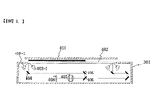
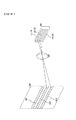
図1に示すカラー画像読み取り装置301において、プラテン402上の原稿401はハロゲンランプ403−1、403−2により照明され、その反射光が第1ミラー404、第2ミラー405、第3ミラー406により順次反射され、次いでレンズ407により結像されて3ラインイメージセンサ408により主走査方向に走査されて光電変換される。ハロゲンランプ403−1、403−2と第1ミラー404は不図示の第1キャリッジに搭載され、第2ミラー405と第3ミ2ー406は不図示の第2キャリッジに搭載され、原稿読み取り時には第1、第2キャリッジが2:1の速度比で図の左から右に移動することにより原稿401が副走査方向に走査されて原稿401の全面が走査される。
【0014】
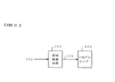
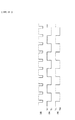
図2に示すようにハロゲンランプ403(403−1、403−2)は照明駆動回路102により駆動される。ここで、照明駆動回路102は図3に示すライン同期信号103に同期してライン毎の駆動パルス信号104(電流値Ia1、Ib1)によりそれぞれハロゲンランプ403を交互に駆動する。このような駆動電流値Ia1、Ib1で駆動することにより、ハロゲンランプ403の色温度105はライン毎に駆動電流値Ia1、Ib1に対してそれぞれ色温度Ta1、Tb1となる。この場合、ハロゲンランプ403の発光強度分布は図4に示すように各ライン毎に異なるので、この光で原稿401を照明してその反射光を色分解することにより、原稿をライン毎に異なる色分解特性で読み取ることができる。
【0015】
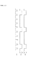
なお、発光強度分布を異なるようにすることができれば、ハロゲンランプ403の代わりに蛍光灯のような放電ランプでもよい。また、各ライン毎に電流値Ia1、Ib1を変化させる代わりに、図5に示すように1ライン間では電流値Ib1’で駆動し、その後の複数ライン間では電流値Ia1’で駆動するようにしてもよい。この場合のハロゲンランプ403の色温度Ta1’、Tb1’も同様には電流値Ia1’、Ib1’に対応して1ライン、複数ライン単位で異なる。
【0016】
このように照明された原稿401は、図6に示すようにR(赤)、G(緑)、B(青)の各CCDイメージセンサ411〜413が副走査方向に等間隔で配列されたセンサ408により光電変換される。なお、Rのセンサ411は原稿401のライン414を読み取り、Gのセンサ412はライン415を読み取り、Bのセンサ415はライン416を読み取る。
【0017】
センサ411、412、413によりそれぞれ読み取られたR、G、Bの各信号は、図7に示すようにアナログ増幅器421、422、423により増幅され、次いでA/D変換器424、425、426によりデジタル画像信号427、428、429に変換される。このデジタル画像信号427〜429はそれぞれ、図8に詳しく示すシェーディング補正回路430、431、432によりハロゲンランプ403の照明むら、センサ411〜413の各受光素子の感度むら等が補正される。
【0018】
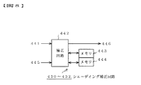
シェーディング補正回路430〜432の各々は、図8に示すように補正回路442とラインメモリ443、444を有し、図1に示す装置301が図示省略の白色基準板を読み取り、次いで原稿401を読み取ると、ラインメモリ443、444にはそれぞれ白色基準板、原稿401を読み取った画像信号441、445が画素毎に格納される。シェーディング補正回路430〜432の各々の補正回路442は、原稿画像信号445を白色基準板画像信号441で画素毎に除算することによりシェーディング補正を行い、補正後のデータ446(433、434、435)を図7、図9に示す遅延補正回路436に出力する。この処理により、色分解特性毎に異なるシェーディング補正が行われるので、例えば白色基準板と同一の色を読み取った場合には、色分解特性が変わっても、または読み取った位置が異なっても原稿画像信号445を同じ値に補正することができる。
【0019】
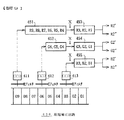
図9に詳しく示すように遅延補正回路436では、上記の読み取り位置のずれを画像信号の遅延により補正して同一箇所の画像信号を生成する。図9に示す数字「01」〜「09」は、原稿401上の読み取りラインを示し、また、センサ411、412、413がそれぞれRフィルタ、Gフィルタ、Bフィルタを介して同時にライン「09」、「06」、「03」を読み取る場合を示している。すなわち、隣接するセンサ411、412、413の読み取り位置はそれぞれ3ラインずつずれている。そこで、遅延回路451(図示R9〜R4)、452(図示G6〜G4)はそれぞれRセンサ411、Gセンサ412により読み取られたR信号、G信号を等倍時には6、3ライン分遅延して図示Xの位置ではRGB信号が同一ライン(R3,G3,B3)になるように補正する。
【0020】
ところで、本実施形態の画像読み取り装置では、色分解特性の切り替えをライン単位で行うので、図示Xの位置で得られる画像信号R3、G3、B3は色分解特性の本来の組み合わせになるとは限らない。この例ではGがR、Bと異なっており、このため図10に詳しく示す補間回路453、454、455は本来の組み合わせの色分解特性(R2’,R2”)、(G2’,G2”)、(B2’,B2”)、に補正する。
【0021】
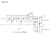
ここで、図10に示す入力画像信号463は、図3に示すようにライン毎に交互に異なる色分解特性で原稿104を読み取った画像信号とする。バッファ461は入力画像信号463をライン同期信号465に同期して1ライン分遅延し、次段のバッファ462は前段のバッファ461により遅延された画像信号464を更にライン同期信号465に同期して1ライン分遅延する。平均化回路467は入力画像信号463とバッファ462により遅延された画像信号466を平均化し、この信号468をセレクタ469、470に出力する。
【0022】
ここで、1ライン毎に交互に異なる色分解特性で原稿を読み取るので、平均化回路467により平均化された画像信号468は、前段のバッファ461により遅延された画像信号464と同じラインを他方の色分解特性で読み取った時の画像信号と見なすことができる。すなわち、他方の色分解特性で読み取ったその前後のラインの画像信号463、466から、平均化方法で予測したものと見なすことができる。そこで、次段のセレクタ469、470が平均化回路467により平均化された画像信号468または前段のバッファ461により遅延された画像信号464をライン同期信号465に同期して選択(出力信号471、472)することにより、特定の色分解特性で読み取った画像信号を選択することができる。
【0023】
図7に戻り、上記の如く遅延補正回路436により、原稿の同一箇所を異なる色分解特性で読み取った時に補正された画像信号は判定回路437に印加される。判定回路437ではこれらの画像信号に基づいて原稿の種類が判定され、判定信号438が出力される。ここで、この原稿の種類の判定は公知の方法で行われ、例えば(B)特開平2−168769号公報に示す方法を用いることができる。また、判定信号438は公知の画像処理に用いられ、例えば色補正処理におけるマスキング係数の切り替え制御、空間フィルタ処理における平滑化/エッジ強調等の切り替え制御等に用いられ、したがって、原稿の種類に応じて最適な画像処理を行うことができる。
【0024】
なお、上記実施形態では、CCDラインセンサ411〜413の読み取り位置のずれが3ラインの場合について説明したが、読み取り位置のずれは常に一定ではない。すなわち、画像読み取り時に変倍処理等を行う場合には、原稿の副走査速度が倍率に応じて変更されるので、読み取り位置のずれもこれに応じて異なる。したがって、上記実施形態では、この変化に応じて図9に示す遅延回路451、452の遅延ライン数も制御される。
【0025】
また、図10において前段のバッファ461により遅延された画像信号464と同じラインを他方の色分解特性で読み取った時の画像信号を求める場合には、平均化回路467によりその前後のラインを平均化したが、本発明はこれに限定されず、例えば読み取り位置のずれのライン数が整数倍でない(端数が生じる)場合には、その端数に応じて重み付け加算することにより、より高い精度で予測することができる。
【0026】
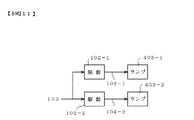
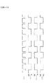
また、図2〜図5に示す原稿照明回路は、代わりに図11〜図14に示すように構成してもよい。すなわち、図11において、ハロゲンランプ403−1、403−2はそれぞれ照明駆動回路102−1、102−2により駆動される。そして、照明駆動回路102−1、102−2はそれぞれ、図12に示すライン同期信号103に同期して、且つ協同してライン毎の駆動パルス信号104−1、104−2(電流値Ia2、Ib2)によりハロゲンランプ403−1、403−2を交互に駆動する。
【0027】
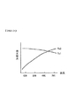
このような駆動電流値Ia2、Ib2で駆動することにより、ハロゲンランプ403−1、403−2の色温度105は、ライン毎に駆動電流値Ia2、Ib21に対してそれぞれ色温度Ta2、Tb2となる。この場合、ハロゲンランプ403−1、403−2の発光強度分布は図13に示すように各ライン毎に異なるので、この光で原稿401を照明してその反射光を色分解することにより、異なる色分解特性で読み取ることができる。
【0028】
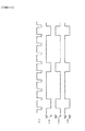
また、同様に、発光強度分布を異なるようにすることができれば、ハロゲンランプ403−1、403−2の代わりに蛍光灯のような放電ランプでもよく、更に、種類が異なるものを用いてもよい。また、各ライン毎に電流値Ia2、Ib2を変化させる代わりに、図14に示すように1ライン間では電流値Ib2’で駆動し、その後の複数ライン間では電流値Ia2’で駆動するようにしてもよい。この場合のハロゲンランプ403−1、403−2の色温度Ta2’、Tb2’も同様には電流値Ia2’、Ib2’に対応して1ライン、複数ライン単位で異なる。但し、図2〜図5に示すように、原稿照明源を共通にしてその駆動方法のみを切り替える方が、図11〜図14に示すように複数の原稿照明源を使用する場合より、部品点数を削減することができるので安価に構成することができる。
【0029】
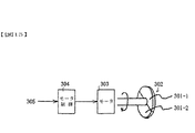
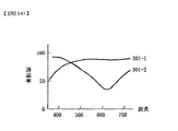
また、本発明では、ライン単位で異なる色分解特性で読み取ることができればよいので、例えば図15に示すようなフィルタ切り替え装置を代わりに用いてもよい。ディスク状の光学フィルタ302は、図16に示すように分光透過特性が異なる半円状の光学フィルタ301−1、302−2により構成され、また、モータ303により矢印で示すように回転する。そして、この光学フィルタ302は光学フィルタ301−1、302−2の1つが図1に示すレンズ407と3ラインイメージセンサ408の間の光軸上に位置するように配置され、モータ制御回路304がライン同期信号305に同期してモータ303を回転させて、ライン毎に光学フィルタ301−1、302−2をセンサ408の間の光軸上に交互に位置するように切り替えることにより、異なった色分解特性で原稿を読み取ることができる。
【0030】
ところで、図5及び図14に示すように、複数ラインに1回の割合で、第1、第2の異なった色分解特性で読み取る場合には、図7に示す判定回路437は、正しい判定信号437を同じく複数ラインに1回の割合で出力し、また、このためにその前後のラインにおいてこの正しいラインの判定信号を膨張させて使用する。なお、原稿上では、原稿の種類が激しく切り替わることがないので、複数ライン毎の判定信号を用いても、最終的な出力画像には殆ど影響することはない。また、同様な理由により、ライン方向の判定も複数画素単位で行うようにしてもよく、この場合には周辺画素の判定結果を使用して最終的な判定を多数決により決定する方法などを採用することができる。
【0031】
また、第2の色分解特性で原稿を読み取った時の画像信号の品質が第1の色分解特性で原稿を読み取った時の画像信号の品質より相対的に劣化する場合がある。例えばハロゲンランプ403の駆動電流104を変える場合に、その値を小さくするとハロゲンランプ403の発光エネルギが小さくなるので、センサ411〜413の出力が小さくなってノイズ成分が相対的に増加し、画像信号の品質が劣化する。そこで、この劣化が激しく、最終的な出力画像に影響する場合には、第2の色分解特性で原稿を読み取る割合を減らすことにより上記の不具合を防止することができる。また、第2の色分解特性で原稿を読み取った時の画像信号は原稿の種類の判定のみに使用して、最終的な出力画像用としては、その前後のラインを第1の色分解特性で原稿を読み取った時の画像信号に基づいて予測して補間することにより、上記の不具合を防止することができる。
【0032】
【発明の効果】
以上説明したように請求項1記載の発明によれば、3ライン型カラーイメージセンサが原稿を読み取る際の色分解特性をライン単位で切り換えて、イメージセンサが出力する各ラインの信号をイメージセンサの位置ずれに応じて遅延して補正し、色分解特性の切り換えと遅延量に応じて原稿の同一ラインを読み取るときの画像信号を補間して原稿の種類を判定するようにしたので、原稿の種類を判定する場合に一般的な3ラインイメージセンサのみを使用し、また、予備的な読み取りを不要にすることができる。
【0033】
請求項2記載の発明によれば、単一の原稿照明手段の分光発光特性をライン単位で切り替えることにより色分解特性をライン単位で切り換えるので、一般的な3ラインイメージセンサのみを使用して簡単な構成でライン単位で異なる色分解特性で読み取ることができる。
【0034】
請求項3記載の発明によれば、分光発光特性が異なる複数の原稿照明手段の1つを選択的にライン単位で駆動することにより色分解特性をライン単位で切り換えるので、一般的な3ラインイメージセンサのみを使用して簡単な構成でライン単位で異なる色分解特性で読み取ることができる。
【0035】
請求項4記載の発明によれば、分光透過特性が異なる複数の光学フィルタの1つを選択的にライン単位でイメージセンサの前の光路上に配置することにより色分解特性をライン単位で切り換えるので、一般的な3ラインイメージセンサのみを使用して簡単な構成でライン単位で異なる色分解特性で読み取ることができる。
【図面の簡単な説明】
【図1】本発明に係るカラー画像読み取り装置の一実施形態を示す構成図である。
【図2】図1のハロゲンランプの照明駆動回路の一例を示すブロック図である。
【図3】図2の回路の主要信号を示すタイミングチャートである。
【図4】図2のハロゲンランプの発光強度分布を示すグラフである。
【図5】図2の照明駆動回路の他の例の照明駆動信号を示すタイミングチャートである。
【図6】図1の3ライン型カラーイメージセンサを示す構成図である。
【図7】図1のカラー画像読み取り装置の主要回路を示すブロック図である。
【図8】図7のシェーディング補正回路を詳しく示すブロック図である。
【図9】図7の補正遅延回路を詳しく示すブロック図である。
【図10】図9の補間回路を詳しく示すブロック図である。
【図11】図1のハロゲンランプの照明駆動回路の他の例を示すブロック図である。
【図12】図11の回路の主要信号を示すタイミングチャートである。
【図13】図11のハロゲンランプの発光強度分布を示すグラフである。
【図14】図11の照明駆動回路の他の例の照明駆動信号を示すタイミングチャートである。
【図15】他の例の色分解特性切り換え手段を示す構成図である。
【図16】図15の光学フィルタの分光透過特性を示すグラフである。
【符号の説明】
102,102−1,102−2 照明駆動回路
403,403−1、403−2 ハロゲンランプ
408,411,412,413 CCDイメージセンサ
436 遅延補正回路
437 判定回路
451,452 遅延回路
453,454,455 補間回路[0001]
BACKGROUND OF THE INVENTION
The present invention relates to a color image reading apparatus that separates and reads a document image, and more particularly to a color image reading apparatus that determines the type of a document.
[0002]
[Prior art]
Conventionally, as this type of color image reading apparatus, for example, (A) JP-B-5-83142, (B) JP-A-2-168769, (C) JP-A-9-465533 is known.
[0003]
By the way, as described in the conventional example (A), depending on the type of document (more precisely, the color material used in the document) It is known to be read. Therefore, in order to detect the type of document, in the conventional example (A), a sensor different from the sensor of the normal three primary colors is provided, and in the conventional example (B), two different sensitivity peaks are provided for each of the three primary colors. In the conventional example (C), a method of reading a document with different color separation characteristics in a frame order is proposed.
[0004]
[Problems to be solved by the invention]
However, in the conventional examples (A) and (B), in order to detect the type of document, a sensor different from the normal three primary color sensors is provided. There is a problem that the configuration of the system becomes complicated. In the conventional example (C), the above-mentioned problem can be solved because no separate sensor is provided. However, since the color separation characteristics are different in the frame order, at least two preliminary operations are required to detect the type of document. There is a problem in that it requires continuous reading, and thus the read processing is not instantaneous.
[0005]
As another method (D), a method of reading a document with different color separation characteristics for each line and simultaneously performing color separation on the same line is conceivable. In this method (D), it is necessary to perform color separation on the same line at the same time. Therefore, there is a problem that a special color separation system (dichroic prism) is required.
[0006]
In view of the above-described conventional problems, the present invention provides a color image reading apparatus that uses only a general three-line image sensor when determining the type of document and can eliminate the need for preliminary reading. The purpose is to do.
[0007]
Another object of the present invention is to provide a color image reading apparatus that can read with different color separation characteristics in units of lines with a simple configuration using only a general three-line image sensor.
[0008]
[Means for Solving the Problems]
In order to achieve the above object, according to a first aspect of the present invention, there is provided a color image reading apparatus in which an original image is color-separated and read by a three-line color image sensor in which three line image sensors are shifted in the sub-scanning direction. Color separation characteristic switching means for switching color separation characteristics when the sensor reads a document in line units, and delay means for delaying and correcting the signal of each line output by the image sensor in accordance with the positional deviation of the image sensor; Interpolating means for interpolating image signals when the three line image sensors read the same line of the original according to the switching by the color separation characteristic switching means and the delay amount of the delay means, and the interpolation by the interpolation means And determining means for determining the type of the document based on the image signal.
[0009]
The second means is characterized in that the color separation characteristic switching means in the first means has a single document illumination means and means for switching the spectral emission characteristics of the document illumination means in line units.
[0010]
In the third means, the color separation characteristic switching means in the first means selectively drives one of the plurality of document illumination means having different spectral emission characteristics and the plurality of document illumination means in units of lines. It is characterized by having.
[0011]
According to a fourth means, the color separation characteristic switching means in the first means selectively arranges one of a plurality of optical filters having different spectral transmission characteristics on the optical path in front of the image sensor in units of lines. It is characterized by.
[0012]
DETAILED DESCRIPTION OF THE INVENTION
Embodiments of the present invention will be described below with reference to the drawings. 1 is a block diagram showing an embodiment of a color image reading apparatus according to the present invention, FIG. 2 is a block diagram showing an example of an illumination drive circuit of the halogen lamp of FIG. 1, and FIG. 3 shows main signals of the circuit of FIG. 4 is a graph showing the emission intensity distribution of the halogen lamp of FIG. 2, FIG. 5 is a timing chart showing an illumination drive signal of another example of the illumination drive circuit of FIG. 2, and FIG. 6 is the three lines of FIG. FIG. 7 is a block diagram showing the main circuit of the color image reading apparatus of FIG. 1, FIG. 8 is a block diagram showing in detail the shading correction circuit of FIG. 7, and FIG. 9 is a correction delay of FIG. FIG. 10 is a block diagram showing in detail the interpolation circuit of FIG. 9.
[0013]
In the color
[0014]
As shown in FIG. 2, the halogen lamps 403 (403-1, 403-2) are driven by the
[0015]
Note that a discharge lamp such as a fluorescent lamp may be used instead of the halogen lamp 403 as long as the emission intensity distribution can be made different. Further, instead of changing the current values Ia1 and Ib1 for each line, as shown in FIG. 5, driving is performed with a current value Ib1 ′ between one line and driving with a current value Ia1 ′ between a plurality of subsequent lines. May be. In this case, the color temperatures Ta1 ′ and Tb1 ′ of the halogen lamp 403 are also different in units of one line and a plurality of lines corresponding to the current values Ia1 ′ and Ib1 ′.
[0016]
As shown in FIG. 6, the original 401 illuminated in this manner is a sensor in which
[0017]
The R, G, and B signals read by the
[0018]
As shown in FIG. 8, each of the
[0019]
As shown in detail in FIG. 9, the delay correction circuit 436 corrects the deviation of the reading position by the delay of the image signal to generate an image signal at the same location. Numbers “01” to “09” shown in FIG. 9 indicate reading lines on the original 401, and the
[0020]
By the way, in the image reading apparatus of the present embodiment, since the color separation characteristics are switched in units of lines, the image signals R3, G3, and B3 obtained at the position X in the drawing are not necessarily the original combination of the color separation characteristics. . In this example, G is different from R and B. Therefore, the
[0021]
Here, the
[0022]
Here, since the original is read with different color separation characteristics alternately for each line, the image signal 468 averaged by the averaging
[0023]
Returning to FIG. 7, the image signal corrected when the same portion of the original is read with different color separation characteristics by the delay correction circuit 436 as described above is applied to the determination circuit 437. A determination circuit 437 determines the type of document based on these image signals, and outputs a
[0024]
In the above embodiment, the case where the deviation of the reading position of the
[0025]
Further, in the case where an image signal obtained by reading the same line as the
[0026]
Also, the document illumination circuit shown in FIGS. 2 to 5 may be configured as shown in FIGS. 11 to 14 instead. That is, in FIG. 11, the halogen lamps 403-1 and 403-2 are driven by the illumination drive circuits 102-1 and 102-2, respectively. Then, the illumination drive circuits 102-1 and 102-2 are synchronized with the
[0027]
By driving with such driving current values Ia2 and Ib2, the
[0028]
Similarly, a discharge lamp such as a fluorescent lamp may be used instead of the halogen lamps 403-1 and 403-2, and different types of lamps may be used as long as the emission intensity distribution can be made different. . Further, instead of changing the current values Ia2 and Ib2 for each line, as shown in FIG. 14, it is driven with a current value Ib2 ′ between one line and driven with a current value Ia2 ′ between a plurality of subsequent lines. May be. In this case, the color temperatures Ta2 ′ and Tb2 ′ of the halogen lamps 403-1 and 403-2 are also different in units of one line and a plurality of lines corresponding to the current values Ia2 ′ and Ib2 ′. However, as shown in FIGS. 2 to 5, it is more common to switch the driving method with a common document illumination source than when a plurality of document illumination sources are used as shown in FIGS. Therefore, it can be configured at low cost.
[0029]
Further, in the present invention, it is only necessary to be able to read with different color separation characteristics for each line, so for example, a filter switching device as shown in FIG. 15 may be used instead. As shown in FIG. 16, the disk-shaped
[0030]
By the way, as shown in FIGS. 5 and 14, in the case of reading with the first and second different color separation characteristics at a rate of once per a plurality of lines, the determination circuit 437 shown in FIG. Similarly, 437 is output to a plurality of lines at a rate of once, and for this purpose, the determination signal of the correct line is expanded and used in the preceding and succeeding lines. It should be noted that since the type of the document does not change drastically on the document, the final output image is hardly affected even if the determination signal for each of the plurality of lines is used. For the same reason, the line direction may be determined in units of a plurality of pixels. In this case, a method of determining a final determination by majority using the determination result of surrounding pixels is adopted. be able to.
[0031]
In some cases, the quality of the image signal when the original is read with the second color separation characteristic is relatively deteriorated than the quality of the image signal when the original is read with the first color separation characteristic. For example, when the driving current 104 of the halogen lamp 403 is changed, if the value is decreased, the light emission energy of the halogen lamp 403 is decreased, so that the outputs of the
[0032]
【The invention's effect】
As described above, according to the first aspect of the present invention, the color separation characteristics when the three-line color image sensor reads an original are switched in units of lines, and the signal of each line output from the image sensor is converted to the image sensor. Since the delay was corrected in accordance with the misregistration, and the color separation characteristics were switched and the image signal when the same line of the document was read was interpolated according to the amount of delay, the document type was determined. Only a general three-line image sensor can be used for determining the image, and preliminary reading can be made unnecessary.
[0033]
According to the second aspect of the present invention, since the color separation characteristics are switched in units of lines by switching the spectral emission characteristics of a single document illumination unit in units of lines, it is easy to use only a general three-line image sensor. Can be read with different color separation characteristics in line units.
[0034]
According to the third aspect of the present invention, the color separation characteristic is switched line by line by selectively driving one of a plurality of document illuminating means having different spectral emission characteristics line by line. It is possible to read with different color separation characteristics for each line with a simple configuration using only a sensor.
[0035]
According to the fourth aspect of the present invention, the color separation characteristics are switched line by line by selectively placing one of the plurality of optical filters having different spectral transmission characteristics on the optical path in front of the image sensor line by line. Using only a general three-line image sensor, it can be read with different color separation characteristics for each line with a simple configuration.
[Brief description of the drawings]
FIG. 1 is a configuration diagram showing an embodiment of a color image reading apparatus according to the present invention.
2 is a block diagram showing an example of an illumination drive circuit of the halogen lamp in FIG. 1. FIG.
FIG. 3 is a timing chart showing main signals of the circuit of FIG. 2;
4 is a graph showing the emission intensity distribution of the halogen lamp of FIG. 2. FIG.
FIG. 5 is a timing chart showing illumination drive signals of another example of the illumination drive circuit of FIG. 2;
6 is a block diagram showing the three-line color image sensor of FIG. 1. FIG.
7 is a block diagram showing a main circuit of the color image reading apparatus of FIG. 1. FIG.
FIG. 8 is a block diagram showing in detail the shading correction circuit of FIG. 7;
FIG. 9 is a block diagram showing in detail the correction delay circuit of FIG. 7;
10 is a block diagram showing in detail the interpolation circuit of FIG. 9. FIG.
11 is a block diagram showing another example of the illumination driving circuit of the halogen lamp in FIG. 1. FIG.
12 is a timing chart showing main signals of the circuit of FIG.
13 is a graph showing the emission intensity distribution of the halogen lamp of FIG.
14 is a timing chart showing illumination drive signals of another example of the illumination drive circuit of FIG.
FIG. 15 is a configuration diagram showing another example of color separation characteristic switching means;
16 is a graph showing the spectral transmission characteristics of the optical filter of FIG.
[Explanation of symbols]
102, 102-1, 102-2 Illumination driving circuits 403, 403-1, 403-2
Claims (4)
前記イメージセンサが原稿を読み取る際の色分解特性をライン単位で切り換える色分解特性切り換え手段と、
前記イメージセンサが出力する各ラインの信号を前記イメージセンサの位置ずれに応じて遅延して補正する遅延手段と、
前記色分解特性切り換え手段による切り換えと前記遅延手段の遅延量に応じて前記3つのラインイメージセンサが原稿の同一ラインを読み取るときの画像信号を補間する補間手段と、
前記補間手段により補間された画像信号に基づいて原稿の種類を判定する判定手段と、
を備えていることを特徴とするカラー画像読み取り装置。In a color image reading apparatus that reads and separates an original image by a three-line color image sensor in which three line image sensors are arranged shifted in the sub-scanning direction,
Color separation characteristic switching means for switching color separation characteristics when the image sensor reads a document in line units;
Delay means for delaying and correcting the signal of each line output by the image sensor in accordance with the positional deviation of the image sensor;
Interpolating means for interpolating image signals when the three line image sensors read the same line of the document according to switching by the color separation characteristic switching means and the delay amount of the delay means;
Determination means for determining the type of document based on the image signal interpolated by the interpolation means;
A color image reading apparatus comprising:
単一の原稿照明手段と、
前記原稿照明手段の分光発光特性をライン単位で切り替える手段と、
を有することを特徴とする請求項1記載のカラー画像読み取り装置。The color separation characteristic switching means is
A single document illumination means;
Means for switching spectral emission characteristics of the original illumination means in line units;
The color image reading apparatus according to claim 1, further comprising:
分光発光特性が異なる複数の原稿照明手段と、
前記複数の原稿照明手段の1つを選択的にライン単位で駆動する手段と、
を有することを特徴とする請求項1記載のカラー画像読み取り装置。The color separation characteristic switching means is
A plurality of document illumination means having different spectral emission characteristics;
Means for selectively driving one of the plurality of document illumination means in units of lines;
The color image reading apparatus according to claim 1, further comprising:
分光透過特性が異なる複数の光学フィルタの1つを選択的にライン単位で前記イメージセンサの前の光路上に配置することを特徴とする請求項1記載のカラー画像読み取り装置。The color separation characteristic switching means is
2. The color image reading apparatus according to claim 1, wherein one of a plurality of optical filters having different spectral transmission characteristics is selectively arranged on a light path in front of the image sensor in units of lines.
Priority Applications (1)
| Application Number | Priority Date | Filing Date | Title |
|---|---|---|---|
| JP31357397A JP3727770B2 (en) | 1997-11-14 | 1997-11-14 | Color image reader |
Applications Claiming Priority (1)
| Application Number | Priority Date | Filing Date | Title |
|---|---|---|---|
| JP31357397A JP3727770B2 (en) | 1997-11-14 | 1997-11-14 | Color image reader |
Publications (2)
| Publication Number | Publication Date |
|---|---|
| JPH11150662A JPH11150662A (en) | 1999-06-02 |
| JP3727770B2 true JP3727770B2 (en) | 2005-12-14 |
Family
ID=18042947
Family Applications (1)
| Application Number | Title | Priority Date | Filing Date |
|---|---|---|---|
| JP31357397A Expired - Fee Related JP3727770B2 (en) | 1997-11-14 | 1997-11-14 | Color image reader |
Country Status (1)
| Country | Link |
|---|---|
| JP (1) | JP3727770B2 (en) |
-
1997
- 1997-11-14 JP JP31357397A patent/JP3727770B2/en not_active Expired - Fee Related
Also Published As
| Publication number | Publication date |
|---|---|
| JPH11150662A (en) | 1999-06-02 |
Similar Documents
| Publication | Publication Date | Title |
|---|---|---|
| US8363294B2 (en) | Image processing apparatus and method of controlling the same | |
| US6765703B1 (en) | Method and apparatus for sensing image | |
| JPH07111561A (en) | Document reader | |
| JP2008022254A (en) | Contact color reading unit, image reading apparatus, image reading method, and program for causing computer to execute the method | |
| JP2007251797A (en) | Image reading apparatus, image processing apparatus, and program | |
| JPH10178513A (en) | Image reader | |
| JP3727770B2 (en) | Color image reader | |
| JP2003087556A (en) | Color signal correction circuit and image reading device | |
| US20060279748A1 (en) | Apparatus and method for compensating for resolution differences of color and monochrome sensors | |
| US6101006A (en) | Method and apparatus for controlling image scanning and data transfer in a photographic film scanner | |
| JP3698814B2 (en) | Color image reader | |
| JP2003319150A (en) | Image processing device | |
| JP2003219111A (en) | Image processing apparatus and control method thereof | |
| JP2996692B2 (en) | Picture reader | |
| JP4042335B2 (en) | Document reader | |
| JP4130180B2 (en) | Image reading apparatus, image forming apparatus, and image reading method | |
| JPS60148280A (en) | Device for reading color original | |
| JP2505823B2 (en) | Document reader | |
| JPH0556218A (en) | Color image reader | |
| JP4070026B2 (en) | Image processing apparatus and program used for the same | |
| JP4334372B2 (en) | Image reading apparatus, image forming apparatus, and image reading method | |
| JP2010124247A (en) | Image processing apparatus, method of image processing, image processing program, and recording medium | |
| KR100198677B1 (en) | Color filter arranging method and color signal processing apparatus using the same | |
| JP2004201136A (en) | Image reading device | |
| JPH0686082A (en) | Image reader |
Legal Events
| Date | Code | Title | Description |
|---|---|---|---|
| A977 | Report on retrieval |
Free format text: JAPANESE INTERMEDIATE CODE: A971007 Effective date: 20050831 |
|
| TRDD | Decision of grant or rejection written | ||
| A01 | Written decision to grant a patent or to grant a registration (utility model) |
Free format text: JAPANESE INTERMEDIATE CODE: A01 Effective date: 20050920 |
|
| A61 | First payment of annual fees (during grant procedure) |
Free format text: JAPANESE INTERMEDIATE CODE: A61 Effective date: 20050929 |
|
| FPAY | Renewal fee payment (event date is renewal date of database) |
Free format text: PAYMENT UNTIL: 20081007 Year of fee payment: 3 |
|
| FPAY | Renewal fee payment (event date is renewal date of database) |
Free format text: PAYMENT UNTIL: 20091007 Year of fee payment: 4 |
|
| FPAY | Renewal fee payment (event date is renewal date of database) |
Free format text: PAYMENT UNTIL: 20101007 Year of fee payment: 5 |
|
| FPAY | Renewal fee payment (event date is renewal date of database) |
Free format text: PAYMENT UNTIL: 20111007 Year of fee payment: 6 |
|
| FPAY | Renewal fee payment (event date is renewal date of database) |
Free format text: PAYMENT UNTIL: 20121007 Year of fee payment: 7 |
|
| FPAY | Renewal fee payment (event date is renewal date of database) |
Free format text: PAYMENT UNTIL: 20131007 Year of fee payment: 8 |
|
| LAPS | Cancellation because of no payment of annual fees |