JP3727698B2 - Fluid filtration device - Google Patents
Fluid filtration device Download PDFInfo
- Publication number
- JP3727698B2 JP3727698B2 JP27827195A JP27827195A JP3727698B2 JP 3727698 B2 JP3727698 B2 JP 3727698B2 JP 27827195 A JP27827195 A JP 27827195A JP 27827195 A JP27827195 A JP 27827195A JP 3727698 B2 JP3727698 B2 JP 3727698B2
- Authority
- JP
- Japan
- Prior art keywords
- fluid
- filtration device
- filter element
- fluid filtration
- cylindrical housing
- Prior art date
- Legal status (The legal status is an assumption and is not a legal conclusion. Google has not performed a legal analysis and makes no representation as to the accuracy of the status listed.)
- Expired - Lifetime
Links
Images


Classifications
-
- B—PERFORMING OPERATIONS; TRANSPORTING
- B01—PHYSICAL OR CHEMICAL PROCESSES OR APPARATUS IN GENERAL
- B01D—SEPARATION
- B01D46/00—Filters or filtering processes specially modified for separating dispersed particles from gases or vapours
- B01D46/24—Particle separators, e.g. dust precipitators, using rigid hollow filter bodies
- B01D46/2403—Particle separators, e.g. dust precipitators, using rigid hollow filter bodies characterised by the physical shape or structure of the filtering element
- B01D46/2407—Filter candles
-
- A—HUMAN NECESSITIES
- A61—MEDICAL OR VETERINARY SCIENCE; HYGIENE
- A61M—DEVICES FOR INTRODUCING MEDIA INTO, OR ONTO, THE BODY; DEVICES FOR TRANSDUCING BODY MEDIA OR FOR TAKING MEDIA FROM THE BODY; DEVICES FOR PRODUCING OR ENDING SLEEP OR STUPOR
- A61M16/00—Devices for influencing the respiratory system of patients by gas treatment, e.g. mouth-to-mouth respiration; Tracheal tubes
- A61M16/08—Bellows; Connecting tubes ; Water traps; Patient circuits
- A61M16/0816—Joints or connectors
- A61M16/0833—T- or Y-type connectors, e.g. Y-piece
-
- A—HUMAN NECESSITIES
- A61—MEDICAL OR VETERINARY SCIENCE; HYGIENE
- A61M—DEVICES FOR INTRODUCING MEDIA INTO, OR ONTO, THE BODY; DEVICES FOR TRANSDUCING BODY MEDIA OR FOR TAKING MEDIA FROM THE BODY; DEVICES FOR PRODUCING OR ENDING SLEEP OR STUPOR
- A61M16/00—Devices for influencing the respiratory system of patients by gas treatment, e.g. mouth-to-mouth respiration; Tracheal tubes
- A61M16/08—Bellows; Connecting tubes ; Water traps; Patient circuits
- A61M16/0816—Joints or connectors
- A61M16/0841—Joints or connectors for sampling
- A61M16/085—Gas sampling
-
- A—HUMAN NECESSITIES
- A61—MEDICAL OR VETERINARY SCIENCE; HYGIENE
- A61M—DEVICES FOR INTRODUCING MEDIA INTO, OR ONTO, THE BODY; DEVICES FOR TRANSDUCING BODY MEDIA OR FOR TAKING MEDIA FROM THE BODY; DEVICES FOR PRODUCING OR ENDING SLEEP OR STUPOR
- A61M16/00—Devices for influencing the respiratory system of patients by gas treatment, e.g. mouth-to-mouth respiration; Tracheal tubes
- A61M16/10—Preparation of respiratory gases or vapours
- A61M16/105—Filters
- A61M16/106—Filters in a path
- A61M16/1065—Filters in a path in the expiratory path
-
- B—PERFORMING OPERATIONS; TRANSPORTING
- B01—PHYSICAL OR CHEMICAL PROCESSES OR APPARATUS IN GENERAL
- B01D—SEPARATION
- B01D46/00—Filters or filtering processes specially modified for separating dispersed particles from gases or vapours
- B01D46/0027—Filters or filtering processes specially modified for separating dispersed particles from gases or vapours with additional separating or treating functions
- B01D46/003—Filters or filtering processes specially modified for separating dispersed particles from gases or vapours with additional separating or treating functions including coalescing means for the separation of liquid
-
- B—PERFORMING OPERATIONS; TRANSPORTING
- B01—PHYSICAL OR CHEMICAL PROCESSES OR APPARATUS IN GENERAL
- B01D—SEPARATION
- B01D46/00—Filters or filtering processes specially modified for separating dispersed particles from gases or vapours
- B01D46/56—Filters or filtering processes specially modified for separating dispersed particles from gases or vapours with multiple filtering elements, characterised by their mutual disposition
- B01D46/58—Filters or filtering processes specially modified for separating dispersed particles from gases or vapours with multiple filtering elements, characterised by their mutual disposition connected in parallel
Landscapes
- Health & Medical Sciences (AREA)
- Chemical Kinetics & Catalysis (AREA)
- Chemical & Material Sciences (AREA)
- General Health & Medical Sciences (AREA)
- Veterinary Medicine (AREA)
- Biomedical Technology (AREA)
- Heart & Thoracic Surgery (AREA)
- Hematology (AREA)
- Life Sciences & Earth Sciences (AREA)
- Animal Behavior & Ethology (AREA)
- Engineering & Computer Science (AREA)
- Public Health (AREA)
- Anesthesiology (AREA)
- Pulmonology (AREA)
- Emergency Medicine (AREA)
- Physics & Mathematics (AREA)
- Geometry (AREA)
- Sampling And Sample Adjustment (AREA)
- Separation Using Semi-Permeable Membranes (AREA)
- Solid-Sorbent Or Filter-Aiding Compositions (AREA)
- Filtering Of Dispersed Particles In Gases (AREA)
- Medicines Containing Material From Animals Or Micro-Organisms (AREA)
Abstract
Description
【0001】
【発明の属する技術分野】
本発明は流体ろ過装置に関し、特に、液体をガスから分離するろ過装置に関する。特に、本発明はガス分析器またはモニタと共に利用できる流体ろ過装置に関する。この流体ろ過装置は、ガス含量の変化に対する前記モニタの応答時間に及ぼす影響が極めて少ない。
【0002】
【従来の技術】
ガス分析器のためのフィルタの現在の技術状態は、2つのカテゴリに分けることができる。すなわち、疎水性のマイクロポーラス膜に基づく技術と、機械的セパレータに基づく技術とである。
【0003】
第1の技術に基づくガスフィルタは、適当なハウジング内に具体化された疎水性のマイクロポーラス膜の平らなシートを共通的に使用している。前記ハウジングの構造は、ドレン液体を集め、かつ、ガス分析器またはモニタに接続するように設計されている。
【0004】
多くの適用では、特に、キャプノグラフ(capnograph)つまり炭酸ガス呼吸モニタの適用では、ガスの波形を乱すことなくガスがろ過媒体を通って流れることが必要である。これは、ガス成分の測定される時間的変動が検査中の呼吸からのみ生じたもので、ガスを測定領域に運ぶ流れ系の部分によって後に導入されたものではないことを保証するために必要である。ガスを自由に運ぶ能力を反映する流体ろ過装置の評価基準は、流体ろ過装置がもたらす応答時間によって定められる。一般に、応答時間はガス成分の変動への応答測定である。長い応答時間は、低い呼吸速度でも出力表示をゆがめるであろうし、そのようなゆがみは、ガス分析器若しくはモニタに表示され、またはガス分析器若しくはモニタに記録される患者の健康状態に関する検査情報の精度に影響を及ぼすかもしれない。
【0005】
キャプノグラフにおいて典型的であるように、低いガス流速で作動するとき、ガス波形への最小のゆがみで短い応答時間のガスフィルタを作るためには、前記ガスフィルタは層流に対する最小の乱れと抵抗とを与えるべきであり、また、ガスフィルタの形状、寸法または材質によって前記波形を乱す、ガスが通過する流体通路を持つべきではない。たとえば、前記流体通路の形状や寸法は、前記ガスフィルタに入るとき、流体通路の面積または体積の急激の変化を許さないようなものでなければならない。そうでないと、前記流体通路の拡大部に入るガスは、そこから上流のガス流れ方向に直角な半径に沿って非常に異なる流速を持つようになる。前記流体通路の中央から最も離れた領域は、中央に比べて非常に遅い流速を持つかもしれない。そのような流速の分布は、患者から異なる時間に来るガスを混合し、応答時間を損なうであろう。ある範囲まで、平滑流れの前記乱れは、拡大部の寸法と急激さとに依存する。ろ過目的のために平らなシート膜を使用するとき、このシート膜の必要とされるできるだけ大きな表面積を提供するためには、面積の急激な変化を伴う大きな体積は避けられない。
【0006】
さらに、ガスが、たとえば0.5mm より大きな相当厚みを有する有孔壁であって液体を吸い込むために使用され、またはろ過媒体として使用される有孔壁の間を、または有孔壁を通って通過しなければならない場合、ガスの自由な損なわれていない流れは、前記有孔壁の内部および外部で拡散するガスの部分によって乱されるであろう。前記有孔壁では、前記ガス流れは、前記有孔壁に入らないガス流れに対応して乱され、それによってガスを混合させる。
【0007】
このゆえに、従来技術の流体フィルタにおける平滑な損なわれていないガス流れへのゆがみは、3つの主な要因によって引き起こされていた。すなわち、
a)ろ過膜の有孔材料および壁の有孔部分を含む、流体ろ過装置の材料そのものによって、その厚みに比例する範囲で、
b)入口と出口との間のガス通路内で急激な変形を呈する、流体ろ過装置そのものの形状または構造によって、そして
c)流体ろ過装置の入口から出口までのガス流れのための通路の体積すなわち空間の全体の大きさによって。
【0008】
前記流体ろ過装置内でろ過されるべき流体が横切る前記通路に関する前記3つの要因はまた、以降「空間」として引用される。ろ過される流体の特性の有効な分析を達成するために、前記流体ろ過装置はできるだけ小さなデッドスペースを持つべきこと、つまり、前記3つの要因が優勢であり、光学分析に有害である前記空間が最小となるべきことが分った。
【0009】
【発明が解決しようとする課題】
前述の流体ろ過装置の不利を除く試みにおいて、ある場合には、前記モニタの分離特徴によって集められるべき、及び(又は)捨てられるべきドレン液を前記膜面から連続的に取り除く手段を適用した。このさらに複雑化した解決は、より小さい寸法の膜の使用を可能にするが、好ましくない寸法及び形状の避けることのできない障害によって流れに高すぎる抵抗を生じさせないために、最小寸法の平らな膜をさらに必要とし、その正しい操作のために限定された配置方向が必須となる。この前もって限定された配置方向は、機械的ろ過装置では基本的な要件であるが、実施のためには必ずしも可能ではない。なぜなら、多くの適用では、たとえば、可搬性モニタでは、ろ過装置は、モニタがどの方向に向けられていても作動しなければならないからである。
【0010】
本発明の流体ろ過装置は、微小体積の流体、たとえば、新生児または老人から分析のために抽出した流体をろ過するのに特に有利である。
【0011】
したがって、本発明の広い目的は、ガス流れに対して限られた干渉を有する構造のガスモニタまたはガス分析器と結合して使用されるべき流体ろ過装置を提供することにある。
【0012】
本発明の別の広い目的は、ガスモニタまたは分析器と結合して使用されるべき流体ろ過装置であってその配置方向が流体ろ過装置の適当な操作を妨げることがなく、流体ろ過装置がそこに働く重力場から独立している流体ろ過装置を提供することにある。
【0013】
本発明のさらに別の目的は、ろ過された非ガス状成分を捕捉し、かつ、収集する手段であって捕捉され、かつ、収集された成分がガス流れを損なうことがない手段を有する流体ろ過装置を提供することにある。
【0014】
【課題を解決するための手段】
本発明に従って、分析されるべきガスから液体を分離する流体ろ過装置が提供される。この流体ろ過装置は、空間を画定する筒状ハウジングであって前記空間と流体の連通状態となる流体通路を定める入口部分及び出口部分を有し、これら入口部分及び出口部分が流体源とガス分析器との間に接続可能に形成されている筒状ハウジングと、この筒状ハウジング内に配置され、ガス以外の物質が通過するのを阻止する液体及び(又は)気体の疎水性の中空ファイバフィルタのフィルタエレメントとを備え、前記筒状ハウジングとフィルタエレメントとの間の小スペースは前記ハウジング内に小体積を形成している。
【0015】
【実施例】
本発明を、本発明がもっと十分に理解できるように、添付の図面を参照していくつかの好ましい実施例と関連して説明する。
【0016】
図面を参照した詳細な説明では、図示した事項は例示であって本発明の好ましい実施例の説明の目的だけのものであり、本発明の原理及び概念の最も有用であり、かつ、容易に理解される説明であると信じられたものを提供する過程で提示したものであることが強調される。この点に関し、発明の基本的理解に必要である詳細以上の詳細な構造を示す試みはされていない。また、図面を参照した説明は、発明のいくつかの形態がいかに実施に際し、具体化されうるかを当業者に明らかにしている。
【0017】
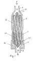
分析されるべき、又は監視されるべきガスから液体及び固体粒子を分離する流体ろ過装置の断面図である図1に示すように、流体ろ過装置は比較的小さい直径の筒状ハウジング2を含む。筒状ハウジング2はその内部に空間4を画定しており、流体通路10を画定する入口端部6と、流体通路12を画定する出口端部8とを有する。入口端部6と出口端部8とは、流体ろ過装置を流体源とガス分析器またはモニタとの間に接続するのに利用でき、この目的のための適当なコネクタを備えることができる。図に見られるように、入口端部6と出口端部8とは、ハウジング2の比較的大きな空間4と入口端部6及び出口端部8の流体通路10、12との間の、平滑な徐々に断面積の変わる遷移部14、16をそれぞれ備えるように形成されている。
【0018】
ハウジング2の内部には、疎水性の中空の複数のファイバフィルタからなる流体のフィルタエレメント18が配置されている。フィルタエレメント18は、前記ファイバフィルタを折り曲げることによって形成することが好ましく、このようにして閉じた第1の端部19と、開いた第2の端部20とを与える。フィルタエレメント18は、閉じた第1の端部19が遷移部14によって定められた空間に到達し、開いた第2の端部20が遷移部16によって定められた空間に到達するように形成され、ハウジング2内に配置されている。ハウジング2の内径と、入口端部6の内径と、出口端部8の内径とは、ハウジング内の自由空間の断面積、すなわち、フィルタエレメント18によって占められていない空間の断面積と、流体通路10または流体通路12とが実質的に同じとなるように算定されていることが有利である。フィルタエレメント18の中空のファイバフィルタは、小直径の筒状ハウジング2と共同して流体ろ過装置を形成する。この流体ろ過装置は、平らな膜タイプのフィルタエレメントを利用することによって得られるデッドスペースより、フィルタ材料のまたは有効フィルタ面積の1平方センチ当り少なくとも4倍小さい体積を有する。ろ過されない流体が出口端部8に到達しないことを確保するために、遮蔽材22が中空のファイバフィルタと開いた端部20におけるハウジング2の壁の内面との間に挿入されている。流体ろ過装置は、ハウジング2内のデッドスペースをさらに減らすための手段24を含むことができる。この手段24は、たとえば、図1に示すようにガラス粒子すなわちビーズである非浸透性の材料によって具体化される。
【0019】
ファイバフィルタの全長に沿う壁はもちろん、フィルタエレメント18の閉じた端部19は薄い壁を提供する。この薄い壁を通ってろ過されるべき流体のガスが最小の乱れで通過する。流体が入口から出口へ最小の圧力と最小の乱れとで通過する効率的な流体ろ過装置を提供する全体の努力において、これから後、前記達成に共同する要素の組合せが提供される。前記要素は次のものを含む。すなわち、
a)入口の流体通路10からハウジング内の空間4への流体流れの急激の遷移を妨げる、部分的にフィルタエレメントによって占められた第1の遷移部14、
b)入って来る流体が、ファイバフィルタの内部の通路であってろ過された流体を入口端部から出口端部まで平滑に案内する通路に到達する前に、入って来る流体を薄い壁だけに通過させるように、一端で閉じられ、他端で開かれた中空のファイバフィルタからなるフィルタエレメント、
c)前記フィルタエレメントを出て行くろ過された流体が出口の流体通路12に到達する前に第2の遷移部16に到達すること。
【0020】
平滑の、乱れのない流体流れをさらに向上するために、前記フィルタエレメントの出口部であってこの出口部を通ってろ過された流体が前記複数のファイバフィルタ、すなわち、出口部にある複数のファイバフィルタを徐々に出て行く前記フィルタエレメントの出口部は、前記複数のファイバフィルタのエッジが1つの面で終るのではなく、むしろ異なる交差断面で終るように形成されている。これによって、ろ過された流体が複数のファイバフィルタ内の通路を離れて遷移部16に入るとき、ろ過された流体を複数のファイバフィルタのいくつかの面を横切って出て行かせる。このように、ろ過の全過程中、ろ過されるべき流体は、前記モニタに流れる間のガス成分と流れ内の同様の乱れとの混合であって、前記流体ろ過装置が接続される系の応答時間を非常に増加させるガスの混合を避けるため非常に注意深く扱われる。換言すると、本発明に従うフィルタエレメントの構造は、息を吐き出すとき、患者の息の連続性を可能な限り保持する一方で、流体のろ過を果たす。
【0021】
50ml/minより低い流速で試料を採るモニタでは、筒状ハウジング2の平均直径は、デッドスペースを減らす手段24がない場合、2.5mm より小さくすべきであることが判明した。しかしながら、さらに高い流速では、筒状ハウジング2の平均直径はそれに応じて増加し、たとえば、約150ml/min の流速では、3.5 mmまでの直径を使用することができる。
【0022】
流体ろ過装置の使用中に集められた液体は、フィルタエレメント18の部分を徐々に浸し、これら部分を不活性にするであろう。やがては、フィルタエレメントの少なくとも主要部が水中に入ったとき、流体ろ過装置は効果がなくなり、取り替えられる。
【0023】
図2に示した本発明の別の実施例に従う流体ろ過装置の有効寿命を延ばすために、筒状ハウジング26またはその一部は、湿気や水蒸気、液体を通過させるがガスの通過を阻止する適当な液体透過材料で作られる。そのような材料の例はナフィオン(Nafion: 登録商標)である。このゆえに、ろ過された液体または液体の少なくとも幾分かは、ハウジング26の壁を通って流体ろ過装置から連続的に除かれる。ナフィオン製のハウジング壁を、平滑の流体流れに有害である曲がりから保護するために、ハウジングの壁は、たとえば、プラスチック製スリーブである編上げスリーブ28で覆われている。そのようなスリーブはナフィオン壁を曲がりと損傷とから保護すると共に、ナフィオン壁の連続換気を可能にする。
【0024】
図3を参照すると、前述のように、湿気や水分の通過を可能にする材料で作られたハウジング26を備えるタイプの流体ろ過装置の実施例が示されている。ハウジング26はジャケット30によって覆われ、ハウジング26とジャケット30との間に液体保持空間が形成されている。ジャケット30は、シリカゲルのような液体吸収材料32を包み込むことが有利である。液体吸収材料32は、空間4内から外部へハウジング26の壁を通って運ばれる液体を吸収するのに使用される。この方法では、ハウジング26の壁は乾燥状態に保たれ、それによってハウジング26の壁の液体通過能力を高めている。
【0025】
ろ過された液体の相当量が除かれる場合、ろ過された液体をより積極的に除く別の手段を図4に示すように設けることができる。そのような手段はノズル34を含み、このノズル34は、囲みであるジャケット30の内部を吸引する真空ポンプに接続できる。ノズル34の入口には疎水性フィルタ36を置くことができ、これによって液体が真空ポンプに到達するのを防止できる。ハウジング38の壁には溜った液体が通過する開口40が開けられている。
【0026】
図5に示した実施例は、Tピース42を組み込んだ患者換気システムと共に利用できるように適合されている。Tピース42の一方の開口44は患者の口に、他方の開口46は換気装置に導かれる。第3の開口48に中空ファイバフィルタのフィルタエレメント18が連結されている。フィルタエレメント18はユニット50に取り付けられている。ユニット50は、Tピース42の開口48に挿入して保持されるように形成された第1部分52と、ノズル部分54とを有し、ノズル部分54はフィルタエレメント18を介してTピース42と流体の連通状態にある。標準の接続ソケット58を一端に有し、ガス分析器またはモニタに導かれるチューブ56は、ノズル部分54に簡単に取り付けることができる。ユニット50の全体は、したがって、取り外すことができ、交換することができる。
【0027】
図からさらに分るように、Tピース42の空気通路は大きいため、比較的大きなろ過面積が得られる。サンプリング用チューブ56は清浄なガスだけを吸引し、このため、チューブ56に接続されるガス分析器またはモニタは凝縮された湿気ガスだけを処理し、一方、唾液、血液その他の液体のような人の排泄物はチューブ56に入るのを阻止される。
【0028】
さらに、非常に薄い膜壁を持つ中空のファイバフィルタは最小の抵抗を与え、Tピース42に沿うガスの速い流れを自由に通過させることができるため、ガス分析器またはモニタの応答時間に及ぼす構造の影響は、多数のファイバフィルタの束がフィルタエレメント18に使用されるときでも、無視できる。疎水性のフィルタエレメント18は、サンプリング用チューブ56が前記空気通路に共通的に見出される患者の排泄物で遮断されたり、充填されたりするのを妨げる利点を流体ろ過装置の応答時間を損なうことなく前記タイプの構造が有することもまた、述べるべきである。前記遮断または充填は、別の構造の流体ろ過装置ではしばしば起こっている。
【0029】
本発明は、図示した実施例についての前述の詳細な説明に制限されるものではないこと、さらに、本発明は発明の精神または本質的特質から離れることなく別の形態でも具体化しうることは、当業者に明らかであろう。したがって、前記実施例は、制限するものではなく、説明のためのものとして考慮されるべきである。
【図面の簡単な説明】
【図1】本発明に係る流体ろ過装置に従う実施例の断面図で、ろ過された液体は筒状のハウジングに集められている。
【図2】本発明に係る流体ろ過装置に従う別の実施例の断面図である。
【図3】ろ過された液体を集めるための別のコンパートメントを図2の流体ろ過装置に備えている流体ろ過装置の断面図である。
【図4】本発明に係る流体ろ過装置に従うさらに別の実施例の断面図で、ろ過された液体を別のコンパートメントに集めて除くバイパス手段を設けている。
【図5】本発明に係る流体ろ過装置のさらに別の実施例の断面図である。
【符号の説明】
2、26、38 筒状ハウジング
4 空間
6 入口端部
8 出口端部
10、12 流体通路
14、16 遷移部
18 フィルタエレメント[0001]
BACKGROUND OF THE INVENTION
The present invention relates to a fluid filtration device, and more particularly to a filtration device that separates liquid from gas. In particular, the present invention relates to fluid filtration devices available together with the gas analyzer or monitor. This fluid filtration device has very little effect on the response time of the monitor to changes in gas content .
[0002]
[Prior art]
The current state of the art of filters for gas analyzers can be divided into two categories. That is, a technique based on a hydrophobic microporous film and a technique based on a mechanical separator.
[0003]
Gas filters based on the first technology commonly use a flat sheet of hydrophobic microporous membrane embodied in a suitable housing. The housing structure is designed to collect drain liquid and connect to a gas analyzer or monitor.
[0004]
In many applications, particularly in capnograph or carbon dioxide breathing monitor applications, it is necessary for the gas to flow through the filtration medium without disturbing the gas waveform. This is necessary to ensure that the measured time variation of the gas component originates only from the breath under examination and is not introduced later by the part of the flow system that carries the gas to the measurement area. is there. The criteria for a fluid filter that reflects the ability to carry gas freely is determined by the response time provided by the fluid filter. In general, the response time is a response measurement to changes in gas components. Long response times will distort the output display even at low breathing rates, and such distortions are displayed on the gas analyzer or monitor, or in the laboratory information regarding the patient's health status recorded on the gas analyzer or monitor. May affect accuracy.
[0005]
As is typical in capnographs, when operating at low gas flow rates, the gas filter has minimal turbulence to laminar flow in order to produce a gas filter with a short response time with minimal distortion to the gas waveform. It should provide resistance, and should not have a fluid passage through which the gas passes, which disturbs the corrugation by the shape, size or material of the gas filter. For example, the shape and dimensions of the fluid passage must be such that when entering the gas filter, it does not allow a sudden change in the area or volume of the fluid passage. Otherwise, the gas entering the enlarged portion of the fluid passage will have very different flow rates along a radius perpendicular to the upstream gas flow direction therefrom. The region farthest from the center of the fluid passage may have a very slow flow rate compared to the center. Such a flow velocity distribution will mix gases coming from the patient at different times and impair the response time. To a certain extent, the disturbance of smooth flow depends on the size and abruptness of the enlarged portion. When using a flat sheet membrane for filtration purposes, a large volume with a sudden change in area is unavoidable in order to provide as much surface area as possible of this sheet membrane.
[0006]
In addition, gas passes between or through perforated walls that are perforated walls with a substantial thickness, for example greater than 0.5 mm, used to suck in liquids or used as filtration media If this has to be done, the free intact flow of gas will be disturbed by the part of the gas diffusing inside and outside the perforated wall. In the perforated wall, the gas flow is disturbed corresponding to the gas flow not entering the perforated wall, thereby mixing the gases.
[0007]
For this reason, distortion to the smooth, intact gas flow in prior art fluid filters has been caused by three main factors. That is,
a) Depending on the material of the fluid filtration device itself, including the perforated material of the filtration membrane and the perforated part of the wall, in a range proportional to its thickness,
b) depending on the shape or structure of the fluid filtration device itself, which exhibits abrupt deformation in the gas passage between the inlet and outlet, and c) the volume of the passage for the gas flow from the inlet to the outlet of the fluid filtration device, i.e. Depending on the overall size of the space.
[0008]
The three factors relating to the passage through which the fluid to be filtered in the fluid filtration device is also referred to hereinafter as “space”. In order to achieve an effective analysis of the properties of the fluid to be filtered, the fluid filtration device should have as little dead space as possible, i.e. the space where the three factors predominate and is detrimental to optical analysis. I found that it should be minimal.
[0009]
[Problems to be solved by the invention]
In an attempt to eliminate the disadvantages of the fluid filtration devices described above, in some cases, means were applied to continuously remove drain liquid from the membrane surface to be collected and / or discarded by the separation features of the monitor. This more complex solution allows the use of smaller sized membranes, but does not create an overly high resistance to flow due to unavoidable obstructions of unfavorable dimensions and shapes, so that the smallest dimension flat membranes And a limited orientation is essential for its correct operation. This pre-defined orientation is a basic requirement for mechanical filtration devices, but is not always possible for implementation. This is because in many applications, for example, in a portable monitor, the filtration device must operate regardless of the orientation of the monitor.
[0010]
The fluid filtration device of the present invention is particularly advantageous for filtering small volumes of fluid, such as fluid extracted from a newborn or elderly for analysis.
[0011]
Accordingly, it is a broad object of the present invention to provide a fluid filtration device to be used in conjunction with a gas monitor or gas analyzer having a structure that has limited interference with gas flow.
[0012]
Another broad object of the present invention is a fluid filtration device to be used in conjunction with a gas monitor or analyzer, the orientation of which does not interfere with the proper operation of the fluid filtration device, and the fluid filtration device is there. The object is to provide a fluid filtration device that is independent of the working gravity field.
[0013]
Yet another object of the present invention is a fluid filtration having means for capturing and collecting filtered non-gaseous components so that the collected components do not impair the gas flow. To provide an apparatus.
[0014]
[Means for Solving the Problems]
In accordance with the present invention, a fluid filtration device for separating a liquid from a gas to be analyzed is provided. The fluid filtration device has a cylindrical housing that defines a space, and has an inlet portion and an outlet portion that define a fluid passage that is in fluid communication with the space, and the inlet portion and the outlet portion serve as a fluid source and a gas analyzer. A cylindrical housing formed so as to be connectable to a container, and a liquid and / or gas hydrophobic hollow fiber filter disposed in the cylindrical housing and blocking passage of substances other than gas. The small space between the cylindrical housing and the filter element forms a small volume in the housing.
[0015]
【Example】
In order that the present invention may be more fully understood, the present invention will be described in connection with certain preferred embodiments with reference to the accompanying drawings.
[0016]
In the detailed description with reference to the drawings, the illustrated matter is exemplary only and is for the purpose of illustrating the preferred embodiment of the present invention and is the most useful and easily understood of the principles and concepts of the present invention. It is emphasized that it was presented in the process of providing what was believed to be the explanation to be made. In this regard, no attempt has been made to show more detailed structure than is necessary for a basic understanding of the invention. Also, the description with reference to the drawings will make clear to those skilled in the art how some aspects of the invention may be embodied in practice.
[0017]
As shown in FIG. 1, which is a cross-sectional view of a fluid filtration device that separates liquid and solid particles from a gas to be analyzed or monitored, the fluid filtration device includes a relatively small diameter
[0018]
A
[0019]
The
a) a
b) Before the incoming fluid reaches the passage inside the fiber filter, which smoothly guides the filtered fluid from the inlet end to the outlet end, the incoming fluid is only applied to the thin wall. A filter element consisting of a hollow fiber filter which is closed at one end and opened at the other end so as to pass through,
c) The filtered fluid exiting the filter element reaches the
[0020]
To further improve the smooth, undisturbed fluid flow, the fluid filtered at and through the outlet of the filter element is the plurality of fiber filters, i.e., the plurality of fibers at the outlet. The exit of the filter element exiting the filter is formed so that the edges of the plurality of fiber filters do not end on one face but rather end on different cross sections. This allows the filtered fluid to exit across several faces of the plurality of fiber filters as the filtered fluid leaves the passages in the plurality of fiber filters and enters the
[0021]
In monitors that sample at a flow rate lower than 50 ml / min, it has been found that the average diameter of the
[0022]
Liquid collected during use of the fluid filtration device will gradually immerse portions of the
[0023]
In order to extend the useful life of the fluid filtration device according to another embodiment of the present invention shown in FIG. 2, the
[0024]
Referring to FIG. 3, an embodiment of a fluid filtration device of the type comprising a
[0025]
If a significant amount of filtered liquid is removed, another means of removing the filtered liquid more positively can be provided as shown in FIG. Such means includes a
[0026]
The embodiment shown in FIG. 5 is adapted for use with a patient ventilation system that incorporates a T-
[0027]
As can be further seen from the figure, the air passage of the
[0028]
In addition, a hollow fiber filter with a very thin membrane wall provides minimal resistance and allows a fast flow of gas along the T-
[0029]
It is to be understood that the present invention is not limited to the foregoing detailed description of the illustrated embodiments, and that the present invention may be embodied in other forms without departing from the spirit or essential characteristics of the invention. It will be apparent to those skilled in the art. Accordingly, the above embodiments should not be construed as limiting, but should be considered as illustrative.
[Brief description of the drawings]
FIG. 1 is a cross-sectional view of an embodiment according to the fluid filtration device of the present invention, in which the filtered liquid is collected in a cylindrical housing.
FIG. 2 is a cross-sectional view of another embodiment according to the fluid filtration device of the present invention.
3 is a cross-sectional view of a fluid filtration device comprising another compartment for collecting filtered liquid in the fluid filtration device of FIG.
FIG. 4 is a cross-sectional view of yet another embodiment according to the fluid filtration apparatus of the present invention, wherein a bypass means is provided for collecting and removing the filtered liquid in another compartment.
FIG. 5 is a cross-sectional view of still another embodiment of the fluid filtration device according to the present invention.
[Explanation of symbols]
2, 26, 38
Claims (18)
空間を定める筒状ハウジングであって前記空間と流体の連通状態になる流体通路をそれぞれ定める入口端部及び出口端部を有し、これら入口端部及び出口端部が流体源とガス分析器との間に接続できるように形成された筒状ハウジングと、
この筒状ハウジング内に配置されたフィルタエレメントであってガス以外の物質が通過するのを妨げる複数の疎水性中空ファイバからなるフィルタエレメントとを備え、
前記筒状ハウジングと前記入口端部及び出口端部とは円筒状であり、前記2つの流体通路のうちの少なくとも一方の断面積は、前記空間内に配置される前記フィルタエレメントの断面積によって占められていない前記空間の断面積と実質的に同じである、流体ろ過装置。A fluid filtration device for separating a liquid from a gas to be analyzed,
A cylindrical housing that defines a space, and has an inlet end and an outlet end that respectively define fluid passages that are in fluid communication with the space, the inlet end and the outlet end being a fluid source, a gas analyzer, A cylindrical housing formed so that it can be connected between,
A filter element arranged in the cylindrical housing, comprising a plurality of hydrophobic hollow fibers that prevent substances other than gas from passing through, and
The cylindrical housing and the inlet end portion and the outlet end portion are cylindrical, and a cross-sectional area of at least one of the two fluid passages is occupied by a cross-sectional area of the filter element disposed in the space. A fluid filtration device that is substantially the same as the cross-sectional area of the space that has not been provided.
Applications Claiming Priority (2)
| Application Number | Priority Date | Filing Date | Title |
|---|---|---|---|
| IL111162 | 1994-10-04 | ||
| IL111162A IL111162A (en) | 1994-10-04 | 1994-10-04 | Filtering device utilizable with gas monitors |
Related Child Applications (1)
| Application Number | Title | Priority Date | Filing Date |
|---|---|---|---|
| JP2005187174A Division JP2005300554A (en) | 1994-10-04 | 2005-06-27 | Fluid filtering apparatus |
Publications (2)
| Publication Number | Publication Date |
|---|---|
| JPH08299764A JPH08299764A (en) | 1996-11-19 |
| JP3727698B2 true JP3727698B2 (en) | 2005-12-14 |
Family
ID=11066605
Family Applications (2)
| Application Number | Title | Priority Date | Filing Date |
|---|---|---|---|
| JP27827195A Expired - Lifetime JP3727698B2 (en) | 1994-10-04 | 1995-10-03 | Fluid filtration device |
| JP2005187174A Pending JP2005300554A (en) | 1994-10-04 | 2005-06-27 | Fluid filtering apparatus |
Family Applications After (1)
| Application Number | Title | Priority Date | Filing Date |
|---|---|---|---|
| JP2005187174A Pending JP2005300554A (en) | 1994-10-04 | 2005-06-27 | Fluid filtering apparatus |
Country Status (7)
| Country | Link |
|---|---|
| US (1) | US5657750A (en) |
| EP (1) | EP0707827B1 (en) |
| JP (2) | JP3727698B2 (en) |
| AT (1) | ATE230953T1 (en) |
| CA (1) | CA2159769A1 (en) |
| DE (1) | DE69529385T2 (en) |
| IL (1) | IL111162A (en) |
Families Citing this family (69)
| Publication number | Priority date | Publication date | Assignee | Title |
|---|---|---|---|---|
| IT1272858B (en) * | 1995-01-03 | 1997-07-01 | Dar Spa | DISPOSABLE ACTIVE HUMIDIFIER PARTICULARLY FOR INSPIRATORY LINES OF RESPIRATORY CIRCUITS FOR INTENSIVE THERAPY |
| DE19621541C1 (en) * | 1996-05-29 | 1997-04-10 | Draegerwerk Ag | Respirator machine humidifier with hollow fibre membrane |
| GB9704241D0 (en) * | 1997-02-28 | 1997-04-16 | Smiths Industries Plc | Gas-treatment devices |
| US5826575A (en) * | 1997-03-13 | 1998-10-27 | Nellcor Puritan Bennett, Incorporated | Exhalation condensate collection system for a patient ventilator |
| US6165244A (en) * | 1999-03-13 | 2000-12-26 | Aaf International, Inc. | Filter media with fluid stream positioned fibers |
| JP2003524149A (en) | 1999-06-08 | 2003-08-12 | オリディオン ブレシド リミティド | Gas analyzer verification test equipment |
| US6656127B1 (en) * | 1999-06-08 | 2003-12-02 | Oridion Breathid Ltd. | Breath test apparatus and methods |
| US6387144B1 (en) | 2000-03-16 | 2002-05-14 | Nelson Industries, Inc. | Enhanced performance fibrous filter media and extended life fluid filter assembly |
| US20020153490A1 (en) * | 2001-03-28 | 2002-10-24 | O'leary Robert | Concentration detection system |
| US20030024528A1 (en) * | 2001-08-04 | 2003-02-06 | Graham James E. | Moisture trap |
| DE60239835D1 (en) * | 2001-12-06 | 2011-06-01 | Carefusion 303 Inc | Infusion device with CO2 monitoring |
| IL148468A (en) | 2002-03-03 | 2012-12-31 | Exalenz Bioscience Ltd | Breath collection system |
| SE0202741D0 (en) * | 2002-09-16 | 2002-09-16 | Aerocrine Ab | scrubber |
| DE60306943T2 (en) * | 2002-09-16 | 2007-02-08 | Aerocrine Ab | GAS CLEANER |
| US7121134B2 (en) * | 2002-10-08 | 2006-10-17 | Ric Investments, Llc. | Integrated sample cell and filter and system using same |
| US7294839B2 (en) * | 2002-10-08 | 2007-11-13 | Ric Investements, Inc. | Low volume sample cell and gas monitoring system using same |
| US7549316B2 (en) * | 2002-10-08 | 2009-06-23 | Ric Investments, Llc. | Integrated sample cell and filter and system using same |
| US7059322B2 (en) * | 2002-10-11 | 2006-06-13 | Ric Investments, Llc. | Low deadspace airway adapter |
| US20040094149A1 (en) * | 2002-11-14 | 2004-05-20 | Creative Biomedics, Inc. | Pulmonary function filter, pulmonary sensor combination and components thereof |
| US20040236242A1 (en) * | 2003-05-22 | 2004-11-25 | Graham James E. | Capnograph system with integral controller |
| US6878938B2 (en) * | 2003-07-16 | 2005-04-12 | Perkinelmer, Inc. | High frequency infrared radiation source |
| FR2858236B1 (en) | 2003-07-29 | 2006-04-28 | Airox | DEVICE AND METHOD FOR SUPPLYING RESPIRATORY GAS IN PRESSURE OR VOLUME |
| US20050042133A1 (en) * | 2003-08-22 | 2005-02-24 | Rosemount Analytical Inc. | Chemical analyzer probe with chemical selective filter |
| US7353689B2 (en) * | 2004-02-17 | 2008-04-08 | Ge Healthcare Finland Oy | Liquid separator for a gas analyzer and method for separating a liquid component from gas |
| US20050217226A1 (en) * | 2004-04-05 | 2005-10-06 | 3M Innovative Properties Company | Pleated aligned web filter |
| JP2006095465A (en) * | 2004-09-30 | 2006-04-13 | Nok Corp | Purifying apparatus |
| US8028697B2 (en) | 2005-04-28 | 2011-10-04 | Trudell Medical International | Ventilator circuit and method for the use thereof |
| WO2006120683A2 (en) * | 2005-05-10 | 2006-11-16 | Oridion Medical Ltd. | Fluid drying mechanism |
| US8240187B2 (en) | 2005-08-16 | 2012-08-14 | Oridion Medical (1987) Ltd. | Breath sampling device and method for using same |
| US8399204B2 (en) * | 2005-09-02 | 2013-03-19 | Eisai R&D Management Co., Ltd. | Method for screening of substance which alter GPR120-mediated cell-stimulating activities |
| JP5507539B2 (en) | 2008-03-17 | 2014-05-28 | ディスカバリー ラボラトリーズ、インク. | Ventilation circuit adapter and proximal aerosol delivery system |
| US8457706B2 (en) | 2008-05-16 | 2013-06-04 | Covidien Lp | Estimation of a physiological parameter using a neural network |
| US8302602B2 (en) | 2008-09-30 | 2012-11-06 | Nellcor Puritan Bennett Llc | Breathing assistance system with multiple pressure sensors |
| US8596265B2 (en) | 2008-10-22 | 2013-12-03 | Trudell Medical International | Modular aerosol delivery system |
| US8434479B2 (en) | 2009-02-27 | 2013-05-07 | Covidien Lp | Flow rate compensation for transient thermal response of hot-wire anemometers |
| CN101569511B (en) * | 2009-05-20 | 2011-01-05 | 曹孟君 | Beauty and health care bathtub |
| US8776787B2 (en) * | 2009-08-20 | 2014-07-15 | Eddie Dewayne JENKINS | Adaptor and breathing assist device using the same |
| US8439036B2 (en) | 2009-12-01 | 2013-05-14 | Covidien Lp | Exhalation valve assembly with integral flow sensor |
| US8469031B2 (en) | 2009-12-01 | 2013-06-25 | Covidien Lp | Exhalation valve assembly with integrated filter |
| US8469030B2 (en) | 2009-12-01 | 2013-06-25 | Covidien Lp | Exhalation valve assembly with selectable contagious/non-contagious latch |
| US8439037B2 (en) | 2009-12-01 | 2013-05-14 | Covidien Lp | Exhalation valve assembly with integrated filter and flow sensor |
| JP5206997B2 (en) | 2010-01-28 | 2013-06-12 | 日本光電工業株式会社 | Gas analyzer |
| USD655405S1 (en) | 2010-04-27 | 2012-03-06 | Nellcor Puritan Bennett Llc | Filter and valve body for an exhalation module |
| USD653749S1 (en) | 2010-04-27 | 2012-02-07 | Nellcor Puritan Bennett Llc | Exhalation module filter body |
| USD655809S1 (en) | 2010-04-27 | 2012-03-13 | Nellcor Puritan Bennett Llc | Valve body with integral flow meter for an exhalation module |
| CN102553366A (en) * | 2010-12-17 | 2012-07-11 | 江苏江分电分析仪器有限公司 | Gas purifying device |
| US9629971B2 (en) | 2011-04-29 | 2017-04-25 | Covidien Lp | Methods and systems for exhalation control and trajectory optimization |
| WO2013046098A2 (en) * | 2011-09-29 | 2013-04-04 | Koninklijke Philips Electronics N.V. | Pressure sensing tube with in-line contaminant blocking |
| US9364624B2 (en) | 2011-12-07 | 2016-06-14 | Covidien Lp | Methods and systems for adaptive base flow |
| US9498589B2 (en) | 2011-12-31 | 2016-11-22 | Covidien Lp | Methods and systems for adaptive base flow and leak compensation |
| US9144658B2 (en) | 2012-04-30 | 2015-09-29 | Covidien Lp | Minimizing imposed expiratory resistance of mechanical ventilator by optimizing exhalation valve control |
| WO2014027290A1 (en) * | 2012-08-15 | 2014-02-20 | Koninklijke Philips N.V. | Sidestream respiratory gas sampling system with flexible accessories and removable water trap |
| USD731049S1 (en) | 2013-03-05 | 2015-06-02 | Covidien Lp | EVQ housing of an exhalation module |
| USD736905S1 (en) | 2013-03-08 | 2015-08-18 | Covidien Lp | Exhalation module EVQ housing |
| USD693001S1 (en) | 2013-03-08 | 2013-11-05 | Covidien Lp | Neonate expiratory filter assembly of an exhalation module |
| USD744095S1 (en) | 2013-03-08 | 2015-11-24 | Covidien Lp | Exhalation module EVQ internal flow sensor |
| USD701601S1 (en) | 2013-03-08 | 2014-03-25 | Covidien Lp | Condensate vial of an exhalation module |
| USD731065S1 (en) | 2013-03-08 | 2015-06-02 | Covidien Lp | EVQ pressure sensor filter of an exhalation module |
| USD692556S1 (en) | 2013-03-08 | 2013-10-29 | Covidien Lp | Expiratory filter body of an exhalation module |
| USD731048S1 (en) | 2013-03-08 | 2015-06-02 | Covidien Lp | EVQ diaphragm of an exhalation module |
| US9950135B2 (en) | 2013-03-15 | 2018-04-24 | Covidien Lp | Maintaining an exhalation valve sensor assembly |
| US10010690B1 (en) | 2013-03-15 | 2018-07-03 | Monitoring For Life, Llc | Endotracheal tube apparatus |
| US9572948B2 (en) * | 2013-12-20 | 2017-02-21 | General Electric Company | Liquid separator for removing a liquid from a sample of a breathing gas and airway adapter |
| US10112024B2 (en) | 2014-01-17 | 2018-10-30 | Monitoring For Life Llc | Medical tube apparatus |
| EP3215253B1 (en) * | 2014-11-03 | 2019-01-09 | ESA European Space Agency | Fluidic filter |
| USD775345S1 (en) | 2015-04-10 | 2016-12-27 | Covidien Lp | Ventilator console |
| US11964106B2 (en) * | 2017-12-21 | 2024-04-23 | Oridion Medical 1987 Ltd. | Bypass filter |
| US11612846B2 (en) | 2018-03-12 | 2023-03-28 | Westmed, Inc. | Low dead space laminar flow water filter for side stream CO2 monitoring lines |
| US11896767B2 (en) | 2020-03-20 | 2024-02-13 | Covidien Lp | Model-driven system integration in medical ventilators |
Family Cites Families (43)
| Publication number | Priority date | Publication date | Assignee | Title |
|---|---|---|---|---|
| US3422008A (en) * | 1963-10-24 | 1969-01-14 | Dow Chemical Co | Wound hollow fiber permeability apparatus and process of making the same |
| US3803810A (en) * | 1972-05-01 | 1974-04-16 | Pall Corp | Liquid-gas separator and filter |
| JPS5949018B2 (en) * | 1976-10-15 | 1984-11-30 | 旭化成株式会社 | drug syringe |
| JPS551816A (en) * | 1978-06-15 | 1980-01-09 | Mitsubishi Rayon Co Ltd | Vapor-liquid contactor |
| US4327718A (en) * | 1980-09-18 | 1982-05-04 | Becton, Dickinson And Company | Continuously draining trap for removal of condensate from a patient breathing circuit |
| US4612019A (en) * | 1982-07-22 | 1986-09-16 | The Dow Chemical Company | Method and device for separating water vapor from air |
| US4456014A (en) * | 1983-01-03 | 1984-06-26 | Thoratec Laboratories Corporation | Flow restrictor |
| US4568366A (en) * | 1983-08-30 | 1986-02-04 | Baxter Laboratories, Inc. | In-line filter |
| US4579568A (en) * | 1983-10-11 | 1986-04-01 | Biochem International Inc. | Gas analyzer separator |
| US4558708A (en) * | 1984-10-24 | 1985-12-17 | Tri-Med, Inc. | Patient's airway adapter to withdraw a patient's gas samples for testing free of sputum mucus and/or condensed water, by utilizing a hollow cylindrical hydrophobic liquid baffle |
| IL76939A (en) * | 1984-11-13 | 1990-01-18 | Andros Analyzers Inc | Adaptor assembly for airway tube |
| JPS61144324A (en) * | 1984-12-19 | 1986-07-02 | Idemitsu Petrochem Co Ltd | Extruding method of thermoplastic resin and extruding device therefor |
| EP0192143B1 (en) * | 1985-02-09 | 1996-01-10 | Asahi Kasei Kogyo Kabushiki Kaisha | Permeable polymer membrane for desiccation of gas |
| US4615694A (en) * | 1985-02-15 | 1986-10-07 | Burron Medical Inc. | Vented cone filter |
| US4678488A (en) * | 1985-05-02 | 1987-07-07 | Sensors, Inc. | Liquid separator for gas analyzer |
| US4668401A (en) * | 1985-06-19 | 1987-05-26 | Mitsubishi Rayon Co., Ltd. | Hollow-fiber filter module and filtration method using the same |
| US4824444A (en) * | 1986-04-11 | 1989-04-25 | Applied Membrane Technology, Inc. | Gas permselective composite membrane prepared by plasma polymerization coating techniques |
| US5064418A (en) * | 1986-05-06 | 1991-11-12 | Microgon, Inc. | Filter means for use with syringe and needle |
| US4713095A (en) * | 1986-10-16 | 1987-12-15 | Criticare Systems, Inc. | Liquid separator for gas analyzer |
| US4852583A (en) * | 1987-01-16 | 1989-08-01 | Spacelabs, Inc. | Airway adapter |
| FI76488C (en) * | 1987-05-05 | 1988-11-10 | Instrumentarium Oy | ROERVATTENAVSKILJARE TILL EN GASANALYSATOR. |
| DE3872378T2 (en) * | 1987-09-10 | 1992-12-10 | Hewlett Packard Co | APPARATUS FOR DRYING DAMP GASES. |
| FI80203C (en) * | 1988-01-11 | 1990-05-10 | Instrumentarium Oy | Method for sealing the water separator membrane in a gas analyzer |
| US4924860A (en) * | 1988-08-26 | 1990-05-15 | Criticare Systems, Inc. | Water trap and associated control system |
| US4985055A (en) * | 1988-12-19 | 1991-01-15 | The Boc Group, Inc. | Liquid/gas separation device |
| US4929259A (en) * | 1989-02-09 | 1990-05-29 | The Dow Chemical Company | Hollow fiber membrane fluid separation module for boreside feed |
| GB8916361D0 (en) * | 1989-07-18 | 1989-09-06 | Smiths Industries Plc | Filters |
| EP0438583A1 (en) * | 1989-08-04 | 1991-07-31 | Nellcor Incorporated | Improved airway adapter with purge means |
| US5101817A (en) * | 1989-08-04 | 1992-04-07 | Nellcor, Inc. | Airway adapter for use with closed suction catheter system |
| US5002590A (en) * | 1989-09-19 | 1991-03-26 | Bend Research, Inc. | Countercurrent dehydration by hollow fibers |
| US5067971A (en) * | 1990-02-12 | 1991-11-26 | Union Carbide Industrial Gases Technology Corporation | Process for dehydration of gases and composite permeable membranes therefor |
| US5026479A (en) * | 1990-02-13 | 1991-06-25 | Union Carbide Industrial Gases Technology Corporation | Fluid separation device |
| US5131387A (en) * | 1990-05-09 | 1992-07-21 | Marquette Gas Analysis Corp. | Moisture trap |
| US5049170A (en) * | 1990-09-11 | 1991-09-17 | Andros Incorporated | Filter assembly for gas analyzer |
| US5071552A (en) * | 1990-12-20 | 1991-12-10 | Union Carbide Industrial Gases Technology Corporation | Multiple bundle fluid separation apparatus |
| US5221474A (en) * | 1990-12-28 | 1993-06-22 | Terumo Kabushiki Kaisha | Transfusion filtering device |
| US5158581A (en) * | 1991-07-29 | 1992-10-27 | Coplan Myron J | Fluid separation membrane module with hollow fibers having segregated active surface regions |
| US5160042A (en) * | 1991-11-05 | 1992-11-03 | Praxair Technology, Inc. | Double ended hollow fiber bundle and fluids separation apparatus |
| FI92138C (en) * | 1991-12-20 | 1994-10-10 | Instrumentarium Oy | Apparatus for separating a liquid component from the breathing air which is led to an analysis unit |
| US5293875A (en) * | 1992-06-16 | 1994-03-15 | Natus Medical Incorporated | In-vivo measurement of end-tidal carbon monoxide concentration apparatus and methods |
| US5282964A (en) * | 1993-02-19 | 1994-02-01 | The Dow Chemical Company | Boreside feed hollow fiber membrane device |
| US5380433A (en) * | 1993-06-01 | 1995-01-10 | E. I. Du Pont De Nemours And Company | Hollow fiber membrane separation device with a housing made from a flexible material |
| US5398677A (en) * | 1993-07-27 | 1995-03-21 | Smith; Charles A. | Condensation collector for respiration system |
-
1994
- 1994-10-04 IL IL111162A patent/IL111162A/en not_active IP Right Cessation
-
1995
- 1995-09-29 US US08/535,345 patent/US5657750A/en not_active Expired - Lifetime
- 1995-10-03 EP EP95307005A patent/EP0707827B1/en not_active Expired - Lifetime
- 1995-10-03 AT AT95307005T patent/ATE230953T1/en not_active IP Right Cessation
- 1995-10-03 DE DE69529385T patent/DE69529385T2/en not_active Expired - Lifetime
- 1995-10-03 JP JP27827195A patent/JP3727698B2/en not_active Expired - Lifetime
- 1995-10-03 CA CA002159769A patent/CA2159769A1/en not_active Abandoned
-
2005
- 2005-06-27 JP JP2005187174A patent/JP2005300554A/en active Pending
Also Published As
| Publication number | Publication date |
|---|---|
| IL111162A0 (en) | 1994-12-29 |
| JP2005300554A (en) | 2005-10-27 |
| DE69529385D1 (en) | 2003-02-20 |
| JPH08299764A (en) | 1996-11-19 |
| US5657750A (en) | 1997-08-19 |
| CA2159769A1 (en) | 1996-04-05 |
| DE69529385T2 (en) | 2003-10-09 |
| EP0707827B1 (en) | 2003-01-15 |
| EP0707827A1 (en) | 1996-04-24 |
| IL111162A (en) | 1998-01-04 |
| ATE230953T1 (en) | 2003-02-15 |
Similar Documents
| Publication | Publication Date | Title |
|---|---|---|
| JP3727698B2 (en) | Fluid filtration device | |
| US4985055A (en) | Liquid/gas separation device | |
| EP1924854B1 (en) | Breath sampling device and method for using same | |
| US5368021A (en) | System for handling and monitoring respiratory waste streams | |
| EP0549266B1 (en) | Apparatus for separating a liquid component from exhalation air to be delivered to an analyzing unit | |
| EP0827713B1 (en) | Multiple channel sample port | |
| US20080027344A1 (en) | Modular sidestream gas sampling assembly | |
| US20180146886A1 (en) | Handpiece for Respiratory Monitor | |
| JP4917218B2 (en) | Method and apparatus for separating water and gas in a gas analysis system | |
| JP2013068630A (en) | Integrated sample cell and filter, and system using them | |
| EP0201565B1 (en) | Adaptor assembly for airway tube | |
| JP4613067B2 (en) | Integrated specimen cell-filter and apparatus using the same | |
| US20230320624A1 (en) | Device for collecting exhaled breath | |
| JP2844890B2 (en) | Dust sampler | |
| CN220650207U (en) | Gas collection device for atmosphere treatment | |
| CN110658189A (en) | Gas collecting device of test tube for analytical chemistry |
Legal Events
| Date | Code | Title | Description |
|---|---|---|---|
| A131 | Notification of reasons for refusal |
Free format text: JAPANESE INTERMEDIATE CODE: A131 Effective date: 20040622 |
|
| A521 | Request for written amendment filed |
Free format text: JAPANESE INTERMEDIATE CODE: A523 Effective date: 20040922 |
|
| A02 | Decision of refusal |
Free format text: JAPANESE INTERMEDIATE CODE: A02 Effective date: 20050329 |
|
| A521 | Request for written amendment filed |
Free format text: JAPANESE INTERMEDIATE CODE: A523 Effective date: 20050627 |
|
| A911 | Transfer to examiner for re-examination before appeal (zenchi) |
Free format text: JAPANESE INTERMEDIATE CODE: A911 Effective date: 20050713 |
|
| TRDD | Decision of grant or rejection written | ||
| A01 | Written decision to grant a patent or to grant a registration (utility model) |
Free format text: JAPANESE INTERMEDIATE CODE: A01 Effective date: 20050830 |
|
| A61 | First payment of annual fees (during grant procedure) |
Free format text: JAPANESE INTERMEDIATE CODE: A61 Effective date: 20050929 |
|
| R150 | Certificate of patent or registration of utility model |
Free format text: JAPANESE INTERMEDIATE CODE: R150 |
|
| FPAY | Renewal fee payment (event date is renewal date of database) |
Free format text: PAYMENT UNTIL: 20091007 Year of fee payment: 4 |
|
| FPAY | Renewal fee payment (event date is renewal date of database) |
Free format text: PAYMENT UNTIL: 20101007 Year of fee payment: 5 |
|
| FPAY | Renewal fee payment (event date is renewal date of database) |
Free format text: PAYMENT UNTIL: 20111007 Year of fee payment: 6 |
|
| FPAY | Renewal fee payment (event date is renewal date of database) |
Free format text: PAYMENT UNTIL: 20111007 Year of fee payment: 6 |
|
| FPAY | Renewal fee payment (event date is renewal date of database) |
Free format text: PAYMENT UNTIL: 20121007 Year of fee payment: 7 |
|
| FPAY | Renewal fee payment (event date is renewal date of database) |
Free format text: PAYMENT UNTIL: 20121007 Year of fee payment: 7 |
|
| FPAY | Renewal fee payment (event date is renewal date of database) |
Free format text: PAYMENT UNTIL: 20131007 Year of fee payment: 8 |
|
| R250 | Receipt of annual fees |
Free format text: JAPANESE INTERMEDIATE CODE: R250 |
|
| R250 | Receipt of annual fees |
Free format text: JAPANESE INTERMEDIATE CODE: R250 |
|
| EXPY | Cancellation because of completion of term |