JP3725293B2 - Terminal crimping device - Google Patents
Terminal crimping device Download PDFInfo
- Publication number
- JP3725293B2 JP3725293B2 JP12392797A JP12392797A JP3725293B2 JP 3725293 B2 JP3725293 B2 JP 3725293B2 JP 12392797 A JP12392797 A JP 12392797A JP 12392797 A JP12392797 A JP 12392797A JP 3725293 B2 JP3725293 B2 JP 3725293B2
- Authority
- JP
- Japan
- Prior art keywords
- shank
- arm
- guide
- ram bolt
- blade
- Prior art date
- Legal status (The legal status is an assumption and is not a legal conclusion. Google has not performed a legal analysis and makes no representation as to the accuracy of the status listed.)
- Expired - Fee Related
Links
Images


Landscapes
- Manufacturing Of Electrical Connectors (AREA)
Description
【0001】
【発明の属する技術分野】
本発明は連鎖端子を一個ずつ切り離しながらこの端子を電線のストリップ部に圧着して取り付ける端子圧着装置に関する。
【0002】
【従来の技術】
従来から端子を電線のストリップ部に圧着して取り付ける端子圧着装置として、図5(a)(b)に示すものが知られている。図5(a)(b)において、端子圧着装置10はフレーム10aに固着された一対の案内ガイド11a,11bと、この案内ガイド11a,11bに沿って上下方向に移動するとともに下端部に上刃13を有するシャンク12と、シャンク12の上刃13に対向して配置された下刃14とを備え、上刃13と下刃14との間で連鎖端子を一個ずつ切り離しながら、端子を図示しない電線のストリップ部に圧着して取付けるようになっている。
【0003】
シャンク12の上部には水平方向に延びる係合溝14が形成され、ラムボルト30が水平方向に移動してラムボルト30の係合突部31が、シャンク14の上部に設けられた係合溝14内に挿入されるようになっている。
【0004】
電線のストリップ部に端子を圧着するには、ラムボルト30の係合突部31をシャンク12の係合溝14内に挿入し、その後ラムボルトを下方に駆動して、シャンク14の下端部に設けられた上刃13と下刃14との間で端子を圧着している。
【0005】
他方、上刃13または下刃14を交換する際、まず案内ガイド11bに設けられた固定用ネジ35によりシャンク12を固定するとともに、下刃14上にゴム36を配置する。次にラムボルト30を水平方向に駆動してシャンク12の係合溝14からラムボルト30の係合突部31を引き抜いた後、上刃13または下刃14の交換を行っている。
【0006】
【発明が解決しようとする課題】
上述のように、ラムボルト30の係合突部31をシャンク12の係合溝14から引き抜く場合、案内ガイド11bに設けられた固定用ネジ35を締め付けることによりシャンク12を案内ガイド11a,11b間で固定するとともに、下刃14上にゴム36を配置し、シャンク12が自重で落下したり、上刃13と下刃14との間にカジリ、破損が生じることを防止している。
【0007】
しかしながら、固定用ネジ35によりシャンク12を固定する構造では、固定用ネジ35の締め付けを忘れたり、下刃14上にゴム36を配置することを忘れると、シャンク12が自重で落下し、これにより上刃13と下刃との間でカジリ、破損が生じてしまう。
【0008】
本発明はこのような点を考慮してなされたものであり、ラムボルトの引き抜き時にシャンク12の落下を確実に防止することができる端子圧着装置を提供することを目的とする。
【0009】
【課題を解決するための手段】
本発明は、一対の案内ガイドに沿って上下方向に移動するとともに下端部に上刃を有し、上部に水平方向に延びる係合溝が形成されたシャンクと、このシャンクの上刃に対向して配置され、前記上刃との間で端子の圧着作用を行う下刃と、前記シャンクの係合溝内に挿入される係合突部を有し、水平方向および上下方向に駆動されるラムボルトとを備え、前記シャンクに水平ガイドを固着するとともに、この水平ガイドに前記係合溝内に挿入されるアームを水平方向に移動自在に設け、このアームを前記係合溝内に付勢するとともに、前記アームに下方へ突出するとともに係合溝へのアーム進入時にストッパにより係止され、係合溝からのアーム後退時にストッパから外れる突出棒を突設したことを特徴とする端子圧着装置である。
【0010】
端子圧着作業を行う際、ラムボルトを水平方向に駆動して係合突部をシャンクの係合溝内に挿入する。この場合、係合突部によりアームが外方へ後退し、これに伴って突出棒がストッパから外れる。次にラムボルトが降下して、シャンクの下端部に設けられた上刃と、上刃に対向して設けられた下刃との間で圧着作業が行われる。次に上刃または下刃を交換する際、ラムボルトを水平方向に駆動して係合突部をシャンクの係合溝から引き抜く。この場合、アームが係合溝側へ進入し、これに伴って突出棒がストッパに係止され、突出棒とストッパによりシャンクの自重落下が防止される。
【0011】
【発明の実施の形態】
以下、図面を参照して本発明の実施の形態について説明する。図1乃至図4は、本発明による端子圧着装置の一実施形態を示す図である。本実施形態において、図5に示す従来技術と同一部分には同一符号を付して詳細な説明は省略する。
【0012】
図1乃至図4に示すように、端子圧着装置10はフレーム10aに固着された一対の案内ガイド11a,11bと、この案内ガイド11a,11bに沿って上下方向に移動するとともに下端部に上刃13を有するシャンク12と、シャンク12の上刃13に対向してフレーム10aに設けられた下刃14とを備え、上刃13と下刃14との間で連鎖端子を一個ずつ切り離しながら、端子を図示しない電線のストリップ部に圧着して取付けるようになっている。
【0013】
シャンク12の上部には水平方向に延びる係合溝12aが形成され、またラムボルト30が水平方向および上下方向に駆動されるようになっている。このラムボルト30はその下端に係合突部31を有し、この係合突部31はシャンク12の係合溝12a内に挿入されるようになっている。
【0014】
さらにまた、シャンク12の側方には水平ガイド15が固着され、この水平ガイド15にはアーム17が水平方向に移動自在に設けられている。このアーム17は、シャンク12の係合溝12a内に常時挿入されているとともに、水平ガイド15に設けられたスプリング16によりシャンク12の係合溝12a側へ進入するよう付勢されている。またアーム17は、ラムボルト30の係合突部31が係合溝12a内に挿入した場合、係合突部31によりスプリング16の力に抗して外方へ後退するようになっている。
【0015】
またアーム17には、下方へ突出する突出棒18が突設されている。この突出棒18は、アーム17の係合溝12aへの進入時に案内ガイド11aの上端に係止してシャンク12の降下を防止するようになっており、またアーム17の係合溝14からの後退時に、案内ガイド11aから外れてシャンク12が降下できるようになっている。このように案内ガイド11aは、突出棒18に対してストッパとしての役割を果すが、案内ガイド11aの他に独立したストッパを設けてもよい。
【0016】
次にこのような構成からなる本実施形態の作用について説明する。
まず、図2(a)(b)に示すように、ラムボルト30を水平方向に駆動して、ラムボルト30の係合突部31をシャンク12の係合溝12a内に挿入する。
【0017】
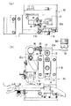
ここで図2(a)はラムボルト30をシャンク12に装着した場合の端子圧着装置の平面図であり、図2(b)はその正面図である。
【0018】
図2(a)(b)に示すように、ラムボルト30の係合突部31がシャンク12の係合溝12a内に挿入されると、ガイド15に設けられた係合突部31がアーム17をスプリング16の力に抗して押し出し、このようにしてアーム17が外方へ後退する。アーム17の後退に伴って、突出棒18が案内ガイド11aから外れ、シャンク12は自由に降下可能となる(図1(b)参照)。
【0019】
次にラムボルト30が下方へ駆動され、シャンク12が降下する。この場合、シャンク17の下端部に設けられた上刃13と、フレーム10aに設けられた下刃14との間で連鎖端子が一個ずつ切り離され、切り離された端子が電線のストリップ部に圧着される。
【0020】
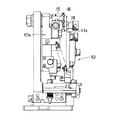
次に上刃13および下刃14を交換する際、図3(a)(b)および図4に示すように、ラムボルト30が水平方向に駆動され、ラムボルト30の係合突部31がシャンク12の係合溝12aから引抜かれる。ここで図3(a)はラムボルト30とシャンク12との装着を解除した場合の端子圧着装置の平面図であり、図3(b)はその正面図である。また図4は端子圧着装置の側面図である。
【0021】
ラムボルト30の係合突部31がシャンク12の係合溝12aから引抜かれると、水平ガイド15に設けられたアーム17がスプリング16の力により係合溝12a側へ進入する。アーム17の進入に伴って、突出棒18が案内ガイド11aの上端に係止され、シャンク12の降下が防止される(図1(a)参照)。
【0022】
図1(a)(b)に示すように、本実施例によれば、突出棒18が案内ガイド11aの上端に係止された場合、シャンク12の降下が防止され、突出棒18が案内ガイド11aの上端から外れた場合、シャンク12が自由に降下できるようになっている。このため、ラムボルト30の係合突部31をシャンク12の係合溝12aから引抜いた場合、シャンク12の自重落下を防止することができ、ラムボルト30の係合突部31をシャンク12の係合溝12aに挿入して確実に端子圧着作業を行うことができる。
【0023】
【発明の効果】
以上説明したように、本発明によれば、ラムボルトの係合突部をシャンクの係合溝内に挿入して、係合突部によりアームを外方へ後退させ、これに伴って案内棒をストッパから外すことにより、端子圧着作業を行うことができる。またラムボルトの係合突部をシャンクの係合溝から引き抜くと、アームが係合溝側へ進入し、これに伴って突出棒がストッパにより係止される。このように突出棒とストッパにより、シャンクの自重落下が防止されるので、上刃と下刃の間のカジリ、破損を確実に防止することができる。
【図面の簡単な説明】
【図1】本発明による端子圧着作業の一実施例を示す斜視図であって便宜上シャンクを取り除いた図。
【図2】端子圧着作業のラムボルトをシャンクに装着した状態を示す図。
【図3】端子圧着装置のラムボルトとシャンクとの装着を解除した状態を示す図。
【図4】端子圧着装置のラムボルトとシャンクとの装着を解除した状態を示す側面図。
【図5】従来の端子圧着装置を示す図。
【符号の説明】
10 端子圧着装置
11a,11b 案内ガイド
12 シャンク
13 上刃
14 下刃
15 水平ガイド
16 スプリング
17 アーム
18 突出棒
30 ラムボルト
31 係合突部[0001]
BACKGROUND OF THE INVENTION
The present invention relates to a terminal crimping apparatus for crimping and attaching this terminal to a strip portion of an electric wire while separating the chain terminals one by one.
[0002]
[Prior art]
2. Description of the Related Art Conventionally, as shown in FIGS. 5 (a) and 5 (b), a terminal crimping apparatus for crimping and attaching a terminal to a strip portion of an electric wire is known. 5 (a) and 5 (b), the
[0003]
An
[0004]
In order to crimp the terminal to the strip portion of the electric wire, the
[0005]
On the other hand, when exchanging the
[0006]
[Problems to be solved by the invention]
As described above, when the
[0007]
However, in the structure in which the
[0008]
The present invention has been made in consideration of such points, and an object thereof is to provide a terminal crimping apparatus that can reliably prevent the
[0009]
[Means for Solving the Problems]
According to the present invention, a shank that moves vertically along a pair of guide guides and has an upper blade at the lower end and an engaging groove extending in the horizontal direction at the upper portion, and the upper blade of the shank are opposed to each other. A ram bolt that is driven in the horizontal direction and the vertical direction, and has a lower blade that crimps a terminal with the upper blade and an engagement protrusion that is inserted into the engagement groove of the shank. The horizontal guide is fixed to the shank, and an arm inserted into the engaging groove is provided in the horizontal guide so as to be movable in the horizontal direction, and the arm is urged into the engaging groove. The terminal crimping device is characterized in that a projecting bar protrudes downward from the arm and is locked by a stopper when the arm enters the engaging groove, and comes out of the stopper when the arm retracts from the engaging groove. .
[0010]
When the terminal crimping operation is performed, the ram bolt is driven in the horizontal direction and the engaging protrusion is inserted into the engaging groove of the shank. In this case, the arm is retracted outward by the engaging protrusion, and the protruding rod is detached from the stopper. Next, the ram bolt is lowered, and a crimping operation is performed between the upper blade provided at the lower end portion of the shank and the lower blade provided facing the upper blade. Next, when exchanging the upper blade or the lower blade, the ram bolt is driven in the horizontal direction and the engaging protrusion is pulled out from the engaging groove of the shank. In this case, the arm enters the engagement groove side, and accordingly, the protruding rod is locked to the stopper, and the protruding rod and the stopper prevent the shank from falling by its own weight.
[0011]
DETAILED DESCRIPTION OF THE INVENTION
Embodiments of the present invention will be described below with reference to the drawings. 1 to 4 are diagrams showing an embodiment of a terminal crimping apparatus according to the present invention. In the present embodiment, the same parts as those in the prior art shown in FIG.
[0012]
As shown in FIGS. 1 to 4, the
[0013]
An
[0014]
Furthermore, a
[0015]
The
[0016]
Next, the operation of the present embodiment having such a configuration will be described.
First, as shown in FIGS. 2 (a) and 2 (b), the
[0017]
2A is a plan view of the terminal crimping apparatus when the
[0018]
As shown in FIGS. 2A and 2B, when the engaging
[0019]
Next, the
[0020]
Next, when the
[0021]
When the
[0022]
As shown in FIGS. 1 (a) and 1 (b), according to the present embodiment, when the protruding
[0023]
【The invention's effect】
As described above, according to the present invention, the engaging protrusion of the ram bolt is inserted into the engaging groove of the shank, the arm is retracted outward by the engaging protrusion, and the guide rod is moved accordingly. The terminal crimping operation can be performed by removing it from the stopper. Further, when the engaging protrusion of the ram bolt is pulled out from the engaging groove of the shank, the arm enters the engaging groove, and accordingly, the protruding rod is locked by the stopper. As described above, since the protruding rod and the stopper prevent the shank from falling by its own weight, it is possible to reliably prevent galling and breakage between the upper blade and the lower blade.
[Brief description of the drawings]
FIG. 1 is a perspective view showing an embodiment of a terminal crimping operation according to the present invention, with a shank removed for convenience.
FIG. 2 is a diagram showing a state in which a ram bolt for terminal crimping work is mounted on a shank.
FIG. 3 is a view showing a state in which the ram bolt and the shank of the terminal crimping device are released.
FIG. 4 is a side view showing a state where the mounting of the ram bolt and the shank of the terminal crimping device is released.
FIG. 5 is a view showing a conventional terminal crimping apparatus.
[Explanation of symbols]
10 Terminal crimping device 11a,
Claims (1)
このシャンクの上刃に対向して配置され、前記上刃との間で端子の圧着作用を行う下刃と、
前記シャンクの係合溝内に挿入される係合突部を有し、水平方向および上下方向に駆動されるラムボルトとを備え、
前記シャンクに水平ガイドを固着するとともに、この水平ガイドに前記係合溝内に挿入されるアームを水平方向に移動自在に設け、このアームを前記係合溝内に付勢するとともに、前記アームに下方へ突出するとともに係合溝へのアーム進入時にストッパにより係止され、係合溝からのアーム後退時にストッパから外れる突出棒を突設したことを特徴とする端子圧着装置。A shank that moves in the vertical direction along a pair of guide guides and has an upper blade at the lower end and an engaging groove extending in the horizontal direction at the upper portion;
A lower blade that is disposed opposite to the upper blade of the shank and performs a crimping action of a terminal with the upper blade;
An engagement protrusion inserted into the engagement groove of the shank, and a ram bolt driven in the horizontal direction and the vertical direction;
A horizontal guide is fixed to the shank, and an arm inserted into the engaging groove is provided in the horizontal guide so as to be movable in the horizontal direction. The arm is urged into the engaging groove, and the arm is attached to the arm. A terminal crimping device characterized by protruding a protruding bar that protrudes downward and is locked by a stopper when the arm enters the engagement groove, and is released from the stopper when the arm retracts from the engagement groove.
Priority Applications (1)
| Application Number | Priority Date | Filing Date | Title |
|---|---|---|---|
| JP12392797A JP3725293B2 (en) | 1997-05-14 | 1997-05-14 | Terminal crimping device |
Applications Claiming Priority (1)
| Application Number | Priority Date | Filing Date | Title |
|---|---|---|---|
| JP12392797A JP3725293B2 (en) | 1997-05-14 | 1997-05-14 | Terminal crimping device |
Publications (2)
| Publication Number | Publication Date |
|---|---|
| JPH10312873A JPH10312873A (en) | 1998-11-24 |
| JP3725293B2 true JP3725293B2 (en) | 2005-12-07 |
Family
ID=14872794
Family Applications (1)
| Application Number | Title | Priority Date | Filing Date |
|---|---|---|---|
| JP12392797A Expired - Fee Related JP3725293B2 (en) | 1997-05-14 | 1997-05-14 | Terminal crimping device |
Country Status (1)
| Country | Link |
|---|---|
| JP (1) | JP3725293B2 (en) |
-
1997
- 1997-05-14 JP JP12392797A patent/JP3725293B2/en not_active Expired - Fee Related
Also Published As
| Publication number | Publication date |
|---|---|
| JPH10312873A (en) | 1998-11-24 |
Similar Documents
| Publication | Publication Date | Title |
|---|---|---|
| CA1043991A (en) | Apparatus for applying a tubular insulating housing to an electrical connector | |
| US5498178A (en) | Electrical wire connecting fixture | |
| JP3119420B2 (en) | Pressure welding harness manufacturing apparatus and manufacturing method | |
| HUE035341T2 (en) | Wire positioning device | |
| JP3725293B2 (en) | Terminal crimping device | |
| JP4212687B2 (en) | Terminal crimping device | |
| KR200347680Y1 (en) | Transfer plate interval control device of terminal clamping machine | |
| KR100450873B1 (en) | Transfer plate interval control device of terminal clamping machine | |
| JP2002050445A (en) | Terminal pressure welding device | |
| JP2003317594A (en) | Relay block | |
| US5050421A (en) | Hand tool for fastening a terminal in an insulator | |
| KR890005823Y1 (en) | Cassette handle system | |
| JPH0950720A (en) | Manufacturing device for pressure-connecting harness and manufacture of pressure-connecting harness | |
| JPH0214256Y2 (en) | ||
| JP6960015B1 (en) | Wire rope socketing jig device and socketing method | |
| CN219811850U (en) | Supplementary operation device for pin supplementing | |
| JPH07335361A (en) | Crimp metal mold structure | |
| KR200405196Y1 (en) | a connector structure | |
| JP2563233Y2 (en) | Crimping device | |
| JP2002044817A (en) | Branch clamp straightening method, and straightening auxiliary tool and jig using this method | |
| JP4370243B2 (en) | Caulking device for optical fiber cable plug | |
| KR20110108668A (en) | Device of removing teeth of slide fastener | |
| US5894658A (en) | Terminal applicator having ram retention feature | |
| JP2559739B2 (en) | Equipment mounting device | |
| JPS6017810Y2 (en) | connector |
Legal Events
| Date | Code | Title | Description |
|---|---|---|---|
| A621 | Written request for application examination |
Free format text: JAPANESE INTERMEDIATE CODE: A621 Effective date: 20040317 |
|
| A977 | Report on retrieval |
Free format text: JAPANESE INTERMEDIATE CODE: A971007 Effective date: 20050808 |
|
| TRDD | Decision of grant or rejection written | ||
| A01 | Written decision to grant a patent or to grant a registration (utility model) |
Free format text: JAPANESE INTERMEDIATE CODE: A01 Effective date: 20050823 |
|
| A61 | First payment of annual fees (during grant procedure) |
Free format text: JAPANESE INTERMEDIATE CODE: A61 Effective date: 20050921 |
|
| R150 | Certificate of patent or registration of utility model |
Free format text: JAPANESE INTERMEDIATE CODE: R150 |
|
| FPAY | Renewal fee payment (event date is renewal date of database) |
Free format text: PAYMENT UNTIL: 20090930 Year of fee payment: 4 |
|
| LAPS | Cancellation because of no payment of annual fees |