JP3722643B2 - Processing method of optical fiber fixture - Google Patents
Processing method of optical fiber fixture Download PDFInfo
- Publication number
- JP3722643B2 JP3722643B2 JP15097099A JP15097099A JP3722643B2 JP 3722643 B2 JP3722643 B2 JP 3722643B2 JP 15097099 A JP15097099 A JP 15097099A JP 15097099 A JP15097099 A JP 15097099A JP 3722643 B2 JP3722643 B2 JP 3722643B2
- Authority
- JP
- Japan
- Prior art keywords
- optical fiber
- ferrule
- polishing
- shaft hole
- spherical surface
- Prior art date
- Legal status (The legal status is an assumption and is not a legal conclusion. Google has not performed a legal analysis and makes no representation as to the accuracy of the status listed.)
- Expired - Fee Related
Links
Images


Description
【0001】
【発明が属する技術分野】
本発明は、光ファイバの接続、脱着を行うための光ファイバ固定具の加工方法に関するものである。
【0002】
【従来の技術】
従来、光通信システムにおける装置の切り替え、送受信ポートの取り外し、装置の調整、測定等の脱着自在な光接続が必要な箇所には、光ファイバを保持した一対の光ファイバ固定具のフェルール先端同士を当接させて連結保持することにより、光ファイバ同士を光学的に接続する光ファイバコネクタが使用されている。
【0003】
その中でアナログ伝送ケーブルテレビシステムに使用される光ファイバコネクタは反射戻り損失を極限にまで小さくする必要があるために、反射減衰量を60dB以上にする必要がある。その為に光コネクタをなす光ファイバ固定具に光ファイバを固定した後、フェルールの端面を光ファイバ軸孔に垂直な面に対してある角度傾斜させた斜め球面に加工すれば良いことが知られている。
【0004】
斜め球面に加工することにより、一対の光ファイバの先端同士が隙間なく接合され、しかも接合面で発生した反射戻り光は光ファイバの長手方向に対して斜め方向に進み、光ファイバのコア部から抜け出てしまう。そのため反射減衰量が60dB以上という高反射減衰量が達成される。
【0005】
例えば、図9は従来一般に使用されている光ファイバコネクタ10を示す縦断面図である。又図10は従来の光ファイバ固定具3のみを示す縦断面図である。フェルール1の先端面1dにC面部1eが設けられており、中心に光ファイバ11を取り付ける軸孔1aが設けられている。C面部1eは一対のフェルール1をそれぞれ両側から受け入れるスリーブ14への円滑な挿入を可能にするため、および脱着時にスリーブ14の内面に擦り傷を発生させないことを目的としたものである。C面部1eは通常軸孔1aに対して30度程度の傾きをもって設けられている。又、先端面1dは斜め球面1fに形成されている。
【0006】
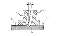
図11は研磨フィルムを用いて光ファイバ11を接合したフェルール1の先端面1dを斜め球面1fに研磨する例を示す断面図である。弾性材質盤51の上面に研磨フィルム52を貼り、その面にフェルール1の先端面1dを所定の角度θになるように傾斜させた孔を設けた研磨冶具53に取り付け、研磨フィルム52に押しつけながら円を描くように摺動させる。斜め球面研磨においてはその必要条件の一つとしては研磨球面の頂点が光ファイバの軸心に一致することが挙げられる。実用的には斜め球面の曲率半径10〜25mmにおいては0.05mm以内に変位量Sを抑えることが要求されているが、前記研磨方法では良好な結果が得られない。
【0007】
図12は前記研磨方法において、研磨したフェルール1の研磨部分の拡大図を示す。この研磨法においては、フェルール1の先端面1dの外縁部より同心円状に研磨除去される性質をもっているので、最終的には図示のように研磨球面Rの頂点は、A点とB点の距離を約2等分した点Pになる。この場合、A点側に比較してB点側の研磨除去量が大きくなるので、点Pは光ファイバ軸心OよりSだけB点側に変位する。傾斜角度θが大きい程変位量Sは大きくなり、曲率半径も研磨除去量の増加に伴って研磨圧力が反比例して減少するので大きくなる方向に変動する。
【0008】
この様にフェルール1の先端面1dにC面部1eを設けた状態で斜め球面研磨を行った場合は、研磨の進行につれて以上のような種々の研磨条件が変動するので、研磨後の曲率半径寸法のばらつき、研磨粗さに代表される研磨面品質のばらつきなどにより、接続性能に悪影響を与える。同時に斜め球面研磨の場合は、直角球面研磨に比較して研磨除去量が10倍以上になるので長時間の研磨時間を必要とし、光ファイバ研磨面に有害な研磨焼けなどが発生しやすく光ファイバ11の劣化要因となるので研磨除去量の低減も課題となっていた。
【0009】
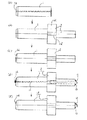
その課題を解決する目的で、図13(a)に示すように、フェルール1は中心に軸孔1aを設けた外周部1h、該外周部1hと同軸で径の小さい直円筒状先端部1g、該直円筒先端部1gと外周部1hを連絡するC面部1eに構成され、図13(b)に示すように、前記フェルール1の軸孔1aに光ファイバ11を接着固定した後、前記直円筒状先端部1gと光ファイバ11の先端部を光ファイバ軸心の直角軸に対し角度θ゜傾けて斜め平坦研磨を行った後に、図13(c)に示すように、斜め球面研磨することにより変位量Sを小さくしていた。(特開平1−1201805、特開平3−210509、特開平6ー201947)
次に第二の従来例として図14(a)、(b)に示すように、フェルール1の中心に軸孔1aを設け、C面部1eの角度を−θ〜+θの範囲で増減させた偏心C面としておき、図14(c)に示すように、光ファイバ11を接着固定した後、先端面1dを光ファイバ軸心の直角軸に対して角度θ゜傾けて斜め平坦研磨し、その後図14(d)に示すように、斜め球面研磨することにより変位量Sを小さくしていた。(特開平7−124855)
更に第三の従来例として図15(a)に示すように、フェルール1に大きなC面部1eを設けておき、先端面1dを最終仕上げ角度θで斜め平坦に研磨しておき、図15(b)に示すように光ファイバ11を接着固定後、先端面1dを最終仕上げ角度を越えた角度θ+αで斜め球面研磨加工をし、図15(c)に示すように変位量Sを小さくしていた。(1996年電子情報通信学会通信ソサエティ大会寄稿集B−991)
【0010】
【発明が解決しようとする課題】
ところが、上記図13に示す第一の従来例では、図13(a)の段階でフェルール1の直円筒状先端部1gの研削加工を行わなければならず、研削代が多い為に、主流であるジルコニアセラミックスを用いた場合、研削加工コストがかなり高価になり、又、図13(b)での斜め平坦研磨時に直円筒状先端部1gと先端面1dの角部に荷重をかけて加工を行うために、研磨開始時に該角部から破壊するということがあった。
【0011】
次に図14に示す第二の従来例では、図14(b)の段階でのフェルール1の加工において、C面部1eが偏心しており外観上の形状が悪いことと、加工方法がかなり特殊であり、研削代が多くしかも偏心しているので研削加工時に加工機への負荷変動が大きくなり、チャック、回転機構のがたつきが生じやすく製品の加工歩留まりが悪くなり、加工コストがかなり高価になるために、一般的な普及にいたっていない。
【0012】
更に図15に示す第三の従来例では、フェルール1に大きなC面部1eの加工を行わなければならず、これも上記従来例同様、高価なフェルールとなってしまう。
【0013】
又、これらの従来例では光ファイバ11を接着固定後、先端面1dを最終仕上げ角度θをこえた角度θ+αで斜め球面研磨加工を行うが、現実的にはその越えた部分の角度αは0.6゜であり、研磨冶具製作上の公差および研磨冶具53と研磨機との取り付け公差等を勘案すると0.6゜に調整するのは非常に困難である。しかも、斜め球面研磨時の研磨量がばらつくので、変位量Sが安定せず、その為、反射減衰量特性が安定しない。
【0014】
いずれの従来例の場合においても、光ファイバ11を接着した後に斜め球面1fを形成する方法では、加工コストが高価になったり、フェルールの破壊が生じたり、外観形状が悪くなったり、または変位量Sが大きくなるなどの課題があった。
【0015】
しかも斜め球面の傾斜方向がよくわからないために、一対の光ファイバ固定具3同士を当接させた時の位置合わせが難しく、互いの斜め球面の傾斜方向が一致しないと一対のフェルール1の先端面1dの頂点が互いに接合しないために接続損失、反射戻り損失が大きくなってしまった。
【0016】
【課題を解決するための手段】
上記課題に鑑みて本発明は、中央に光ファイバを挿入固定するための軸孔を有し、かつ、先端面に上記軸孔に垂直な面に対して傾いた斜め球面を形成したフェルールの後端にフェルール支持体を接合してなる光ファイバ固定具の製造方法であって、上記斜め球面の傾斜方向と、フェルール外周と軸孔との軸ずれ位置を確認後、その方向にあわせて傾斜方向と軸ずれ方向を兼用した傾斜方向表示部が形成されたフェルール支持体をフェルールに固定し、該傾斜方向表示部を基準として光ファイバ固定具の先端面に軸孔に垂線な面に対して傾いた斜め球面を形成することを特徴とするものである。
また、上記フェルール支持体をフェルールに固定した後、上記斜め球面の傾斜方向と、フェルール外周と軸孔との軸ずれ位置を確認し、その方向にあわせて傾斜方向と軸ずれ方向を兼用した傾斜方向表示部をフェルール支持体に形成し、該傾斜方向表示部を基準として光ファイバ固定具の先端面に軸孔に垂線な面に対して傾いた斜め球面を形成することを特徴とするものである。
さらに、上記フェルールの先端面の斜め球面は、予め先端面に斜め球面を形成した後、光ファイバを挿入固定し、仕上げ研磨により形成されたものであることを特徴とするものである。
【0022】
【発明の実施の形態】
以下本発明の実施形態を説明する。
【0023】
図1は本発明の第一実施形態を示す、光ファイバ固定具3を用いた光ファイバコネクタ10を示す断面図である。
【0024】
本発明に係わる光ファイバコネクタ10は、一対の光ファイバ固定具3同士を当接させたものである。この光ファイバ固定具3は、光ファイバ11を挿通固定する軸孔1aを有するフェルール1と、該フェルール1が嵌合する凹部2aを備え、上記凹部2aと連動しかつ前記フェルール1の軸孔1aと同軸の貫通孔2bを有するフェルール支持体2とからなり、上記フェルール1の軸孔1aには光ファイバ11を挿入し、上記フェルール支持体2の貫通孔2bに接着剤13を充填する事により上記光ファイバ11を固着してなるものである。
【0025】
上記光ファイバ固定具3は外周部1hから先端面1dにかけてC面部1eを有し、該先端部1dは光ファイバ11先端部とともに斜め球面1fに研磨仕上げされている。そして、光ファイバコネクタ10は一対の光ファイバ固定具3と、該光ファイバ固定具3のフェルール1の先端同士を当接させて連結保持するスリーブ14とから構成してあり、該スリーブ14の外周には両端にネジ部を設けたアダプタカプリング15を配設すると共に、該アダプタカプリング15のネジ部にカプリングナット16を螺合して各カプリングナット16とフェルール支持体2との間に配設したバネ17の押圧力により光ファイバ固定具3のフェルール1先端同士を当接させることにより光ファイバ11同士を光学的に接続するようにしてある。
【0026】
次に、光ファイバコネクタ10を構成する光ファイバ固定具3について詳細に説明する。
【0027】
図2は光ファイバ固定具3のみを示す縦断面図であり、フェルール1の先端面1dと外周部1hとの間にC面部1eが設けられており、中心に光ファイバ11を取り付ける軸孔1aが設けられており、その中に光ファイバ11が接着固定されている。前記C面部1eはフェルール1をそれぞれ両側から受け入れるスリーブ14への円滑な挿入を可能にするため、および脱着時にスリーブ14の内面に擦り傷を発生させないことを目的としたものであり、通常軸孔1aに対して30度程度の傾きをもって設けられている。
【0028】
又、前記先端面1dは軸孔1aの垂線に対して最終仕上げ角度θ゜傾けた斜め球面1fを形成し、その角度は6゜〜10゜が一般的である。曲率半径Rは10〜25mmである。斜め球面1fの頂点が、A点とB点の距離を約2等分した点と合致し、光ファイバ軸心Oとほぼ一致しており、その変位量Sは0.05mm以内となっている。又、フェルール支持体2のツバ部2cには斜め球面の方向を示した傾斜方向表示部2dを設けた構成としてある。
【0029】
ここで最終仕上げ角度θを6〜10゜としたのは、6゜未満では反射減衰量失が60dBを越えることがなく、又10゜を越えると接続損失が0.4dBを越えてしまい、アナログ伝送ケーブルテレビシステムに使用出来なくなるからである。光学特性上は中間値である8゜が好ましく、一般的に適用されている。
【0030】
曲率半径Rを10〜25mmとしたのは、10mm以下であるとフェルール1の先端部1dからの光ファイバ11のとびだしが大きくなり、一対の光ファイバコネクタとしてフェルール1の先端面1d同士を当接させたときに、バネ17の力により先端面1dが共に斜め平坦に変形し、光ファイバ11同士を光学的に接続することが出来るが、高温高湿環境においては接着剤13のクリープ現象が生じ、軸孔1aと光ファイバ11との接着剥離が生じる。又、25mmを越えると曲率半径Rが大きすぎて、前記バネ17の力では先端面1dが平坦にならず、光ファイバ11同士の光学的な接続が困難となるからである。
【0031】
変位量Sを0.05mm以内としたのは、これを越えると、一対の光ファイバコネクタとしてフェルール1の先端面1d同士を当接させたときに、互いの斜め球面1fの頂点があわず、先端面1dが斜め平坦になりきれず、光ファイバの光学的な接続が困難になるからである。
【0032】
又、前記傾斜方向表示部2dはフェルール支持体2だけでなくフェルール1自体に取り付けることも出来る。
【0033】
次に図3(a)〜(e)に光ファイバ固定具3の斜め球面加工手順を示す。
【0034】
図3(a)はフェルール1を表している。一般的に製造、販売されているSCフェルールであり、材質はジルコニアセラミックスが一般的であり、量産品を用いているのでフェルール1としては低価格である。好ましくは、更に価格を低減させる目的で先端面1dを研磨面とせず、研削面のままでも十分である。
【0035】
フェルール1の材質としては、ジルコニアだけではなく、アルミナ、ほう珪酸ガラス、結晶化ガラス等のセラミックス材料や、ステンレス、黄銅、真鍮、洋泊等の金属材料、そして液晶ポリマー、エポキシ、ポリエーテルイミド、ポロエーテルサルホン、ポロブチレンテレタフレート等の樹脂材料を用いることが出来る。
【0036】
図3(b)はフェルール1にフェルール支持体2を圧入、接着、もしくは一体成形により固定した状態を示す。
【0037】
フェルール支持体2の材質としては、ステンレス、黄銅にニッケルメッキを施したもの、真鍮にニッケルメッキを施したもの、洋白にニッケルメッキを施したもの等の金属材料や、液晶ポリマー、エポキシ、ポリエーテルイミド、ポロエーテルサルホン、ポロブチレンテレタフレート等の樹脂材料を用いることが出来る。 又フェルール1とフェルール支持体2を樹脂材料等で一体で形成しても良い。
【0038】
図3(c)はフェルール1の先端面1dに斜め球面研削加工を行った状態を示す。
【0039】
図3(d)は光ファイバ固定具3に光ファイバ11を接着固定した状態を示す。図3(e)はフェルール1の先端面1dと光ファイバ先端面を同時に最終の仕上げ研磨を行った状態を示す。
【0040】
この様に本発明の光ファイバ固定具3は、光ファイバ11を接着していない状態で予めフェルール1の先端面1dに予め斜め球面1fを施してあるため、加工が容易であり製造工程を簡略化できる。その後、本発明の光ファイバ固定具3に光ファイバ11を接着し、最終仕上げ研磨すれば良い。
【0041】
また、図3(b)に示すようにフェルール支持体2のツバ部2cには、あらかじめ斜め球面の方向を示すための傾斜方向表示部2dを形成しておき、この方向に併せて斜め球面1fを加工する。
【0042】
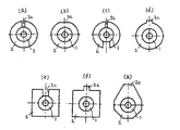
この傾斜方向表示部2dを形成する場合は、図4(a),図4(b)に示すように、フェルール支持体2の外周面に1ヶ所の溝や切り欠きを備えたり、図4(c)に示すように2ヶ所以上の溝を備えるか、もしくはその溝の幅を変えたり、(d)に示すように突起を形成したり、図4(e),図4(f)に示すように外周面を多角形として溝または突起を形成したり、図4(g)に示すように外周面を多角形としてその一部の形状を変形させるなど、様々な構造とすることが出来る。
【0043】
また、フェルール1自体に傾斜方向表示部を付けるこもできるが、この場合、フェルール1の外周部1eでフェルール支持体2に取り付ける部分及びスリーブ14に挿入される部分を除いた部分が望ましい。
【0044】
上記斜め球面の傾斜方向表示部2dは、実際の斜め球面の傾斜方向に対して±5゜以内の範囲に形成されている必要がある。これはそれ以上の範囲にあると一対の光ファイバ固定具3同士を当接させた場合に、互いの斜め球面1fが接触しなくなり光学特性を悪化させるためである。
【0045】
図5(a)は図3(c)における斜め球面研削加工工程を示す側面図であり、図5(b)は回転装置61の取付部64とフェルール支持体2の位置表示部2dとの位置関係を示す平面図である。、
回転装置61の軸芯に対しある一定量Δで偏芯させた位置に取付部62を配置し、フェルール支持体2の傾斜方向表示部2dを位置方向合わせ部64に嵌合させ、長軸部2eをチャック62aで固定して、回転装置62を回転させ、該取付部62の軸心に対してある角度βをもって取り付けたダイヤモンド製カップ砥石63を回転させ斜め球面1fを形成する。チャックで固定する部分は長軸部2eでなくとも、フェルール1外周部1dでも同様の効果が得られる。
【0046】
斜め球面寸法は、最終仕上げ斜め球面寸法と同一でよい。つまり研磨角度は最終仕上げ角度θである6〜10゜、球面の曲率半径Rは10〜25mm、変位量Sは0.05mm以下で最終寸法に合わせてあればよい。この理由は、図3(e)での最終仕上げ研磨において、先端面1dは予め球面加工されており、仕上げ研磨の削り代は0.03mm程度で非常に微量であるために、最終仕上げ斜め球面寸法にもほとんど影響を与えないからである。しかし、好ましくはθが7.5〜8.5゜、Rは15〜20mm、Sは0.03mm以下の範囲であれば、更に優れた効果が得られる。
【0047】
従来の光ファイバを接着したファイバ固定具においては、該光ファイバ固定具自体が回転するために光ファイバもそれに伴い回転し、しまいには破断してしまうのでこの加工方法を適用することが出来ない。その為、本発明の光ファイバを接着する前の光ファイバ固定具に斜め球面加工するのには非常に適した方法である。
【0048】
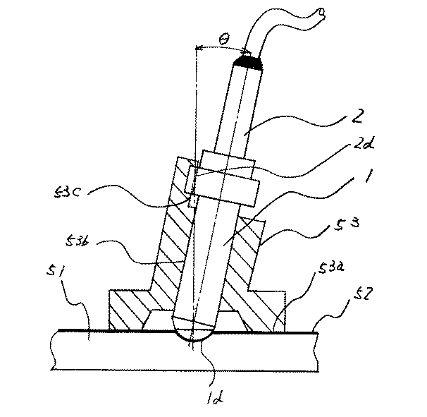
図6は図3(e)における最終仕上げ研磨加工を示す図である。
【0049】
弾性材質盤51の上面に研磨フィルム52を貼り、その面に弾性材質盤51の垂直に対して所定の角度θになるように傾斜させた孔を設けた研磨冶具53に取り付け、研磨フィルム52に押しつけながら円を描くように摺動させる。
【0050】
光ファイバ固定具3のフェルール1を底面部53aの垂直面に対し所定の角度θになるように傾斜させた孔53bを設けた研磨冶具53に入れ、フェルール支持体2の傾斜方向表示部2dを研磨冶具53の固定部53cに合わせた状態で、フェルール1の先端面1dと光ファイバ先端面を同時に仕上げ研磨を行う。
【0051】
前記仕上げ研磨は最終仕上げ角度θでなくともθ±5゜の範囲の角度で斜め球面研磨をすればよい。この理由は、先端面1dは予め球面加工されており、仕上げ研磨の削り代は0.03mm程度で非常に微量であるために、角度が多少違っても最終仕上げ研磨角度に影響を与えないからである。
【0052】
本発明は、フェルール1の先端面1dにと外周部1hとの間にC面部1eにより構成されている光ファイバ固定具3のみならず、フェルール1の外周部1hと同軸で径の小さい直円筒状先端部1g、前記直円筒先端部1gと外周部1hを連絡するC面部1eにより構成されている光ファイバ固定具3にも適用でき、同様の効果を得ることが出来る。
【0053】
以上のような方法であれば、反射減衰量、接続損失の光学的特性はアナログ伝送ケーブルシステム等の厳しい要求値に対して、要求値を満足する安定した特性値を示し、しかも安価な光ファイバ固定具を供給できる。
【0054】
次に、本発明の第二の実施形態を説明する。
【0055】
図7は本発明の第二の実施様態を示す光ファイバ固定具3を示す縦断面図であり、フェルール1の先端面1dと外周部1hとの間にC面部1eが設けられており、中心に光ファイバ11を取り付ける軸孔1aが設けられており、その中に光ファイバ11が接着固定されており、フェルール支持体2のツバ部2cには斜め球面の方向を示した傾斜方向表示部2dを設けてあり、該位置表示部2dはフェルール外周部1hと軸孔1aの軸ずれ位置方向を兼ね備えた構成としてある。
【0056】
この傾斜方向と軸ずれ位置方向と傾斜方向表示部2dは必ず一致させる必要はなく、図7でたとえると、傾斜方向表示部2dは図通りの下方向で、傾斜方向は図と180度反対側の上方向で、軸ずれ位置方向は図の90゜回転した右方向であってもかまわず、一定の法則のもとで一対の光ファイバ固定具3が当接されていればよい。上記傾斜方向表示部2dはフェルール支持体2だけでなくフェルール1自体に取り付けつけることも出来る。
【0057】
図8は本発明の第二の実施様態である光ファイバ固定具の製造方法を示す流れ図であり、フェルール1単体の軸ずれ方向を確認後、その方向にあわせて傾斜方向表示部2dのついたフェルール支持体2に挿入、固定するか、もしくはフェルール1に傾斜方向表示部2dをつけていないフェルール支持体2を固定後、軸ずれ方向を確認し、その後傾斜方向表示部を作成するかした後、第一の実施様態の通り、傾斜方向表示部2d基準に斜め球面加工を行う。
【0058】
以上の様な方法であれば、斜め球面1fの傾斜方向と、フェルール外周1hと軸孔1aの軸ずれ位置方向を概ね一致させ、フェルール1もしくはフェルール支持体2に傾斜方向を兼用した表示部を形成させることにより、反射減衰量、接続損失の光学的特性はアナログ伝送ケーブルシステム等の厳しい要求値に対して、要求値を満足する安定した特性値を示し、しかも安価な光ファイバ固定具を供給することができる。
【0059】
【実施例】
ここで、以下に示す方法で実験を行った。
【0060】
ジルコニアセラミックス製のシングルモードフェルールの外径D=φ2.5mm、長さL=10.5mm、軸孔D=φ0.126mmで比較例として図13に示した第一の従来例であるフェルール外径を二段にしたもの、図14に示した第二の従来例であるC面を偏心させたもの、図15に示した第三の従来例である大きなC面を施したものに、本発明の第一の実施様態である加工方法のもの、第二の実施様態である軸ずれも調整したものの6種類をそれぞれ20個サンプルを作成した。上記サンプルに光ファイバを接着し、端面を研磨し、バネ、カプリングナット等を組み立てて光ファイバコネクタとし、接続損失と反射減衰量を測定し、平均値を算出した。
【0061】
その結果を表1に示す。このように、従来の方法では反射減衰量が小さく、しかも接続損失が大きいのに対し、本発明では反射減衰量が大きくしかも接続損失が小さい、特に第二の実施様態では接続損失が顕著に小さくなっていることが確認できる。
【0062】
【表1】
次に、斜め球面の方向表示部が、実際の斜め球面の傾斜方向に対しての位置角度公差を確認するために、上記同様ジルコニアセラミックス製のシングルモードフェルールの外径D=φ2.5mm、長さL=10.5mm、軸孔D=φ0.126mmで比較例として、±0゜、±3゜、±5゜、±6゜、±8゜の5種類をそれぞれ20個サンプルを作成し、上記サンプルに光ファイバを接着し、端面を研磨し、バネ、カプリングナット等を組み立てて光ファイバコネクタとし、接続損失と反射減衰量を測定し、平均値を算出した。
【0064】
その結果を表2に示す。このように、±5゜以下であれば良好な光学特性が得られるが、±5゜を越えると極端に特性が悪化することが確認できる。
【0065】
従って、中央に光ファイバを挿入固定するための軸孔を有するフェルールの後部にフェルール支持体を接合してなる光ファイバ固定具であって、上記フェルールの先端面に上記軸孔に垂直な面に対して傾いた斜め球面を形成し、及び上記斜め球面の傾斜方向にあわせ、フェルールもしくはフェルール支持体に傾斜方向表示部を形成し、及び/もしくは、上記斜め球面の傾斜方向表示部が、実際の斜め球面の傾斜方向に対して、±5゜以内の範囲に形成し、及び上記斜め球面の傾斜方向と、フェルール外周と軸孔との軸ずれ位置方向を概ね一致させ、フェルールもしくはフェルール支持体に傾斜方向と軸ずれ方向を兼用した表示部を形成することにより接続損失、反射減衰量共に優れた効果が得られた。
【0066】
【表2】
【発明の効果】
以上のように本発明によれば、中央に光ファイバを挿入固定するための軸孔を有し、かつ、先端面に上記軸孔に垂直な面に対して傾いた斜め球面を形成したフェルールの後端にフェルール支持体を接合してなる光ファイバ固定具の製造方法であって、上記斜め球面の傾斜方向と、フェルール外周と軸孔との軸ずれ位置を確認後、その方向にあわせて傾斜方向と軸ずれ方向を兼用した傾斜方向表示部が形成されたフェルール支持体をフェルールに固定し、該傾斜方向表示部を基準として光ファイバ固定具の先端面に軸孔に垂線な面に対して傾いた斜め球面を形成するものであるか、または、上記フェルール支持体をフェルールに固定した後、上記斜め球面の傾斜方向と、フェルール外周と軸孔との軸ずれ位置を確認し、その方向にあわせて傾斜方向と軸ずれ方向を兼用した傾斜方向表示部をフェルール支持体に形成し、該傾斜方向表示部を基準として光ファイバ固定具の先端面に軸孔に垂線な面に対して傾いた斜め球面を形成するものであるため、接続損失、反射減衰量共に優れた光ファイバ固定具を提供できるという効果を得ることが出来る。
【図面の簡単な説明】
【図1】本発明の光ファイバ固定具を用いた光ファイバコネクタを示す断面図である。
【図2】本発明の光ファイバ固定具を示す縦断面図である。
【図3】本発明の光ファイバ固定具の斜め球面加工手順を示す図である。
【図4】(a)〜(g)は本発明の光ファイバ固定具のフェルール支持体の外周面に備える傾斜方向表示部の様々な実施形態を示す図である。
【図5】本発明の図3(c)における斜め球面研削加工を示す図である。
【図6】本発明の図3(e)における最終仕上げ研磨加工を示す図である。
【図7】本発明の第二の実施様態の光ファイバ固定具を示す縦断面図である。
【図8】本発明の第二の実施様態の光ファイバ固定具の製造方法を示す流れ図である。
【図9】従来の光ファイバコネクタを示す縦断面図である。
【図10】 従来の光ファイバコネクタに備える光ファイバ固定具を示す縦断面図である。
【図11】従来のフェルールの先端面に軸孔に垂直な面に対して傾いた斜め球面の研磨加工方法を示す図である。
【図12】従来の研磨方法によるフェルールの研磨部分を示す拡大図である。
【図13】(a)〜(c)は従来のフェルールの先端面の変位量を小さくするための加工手順を示す図である。
【図14】(a)〜(d)は従来のフェルールの先端面の変位量を少なくするための加工手順を示す図である。
【図15】(a)〜(c)は従来のフェルールの先端面の変位量を少なくするための加工手順を示す図である。
【符号の説明】
1 フェルール
1a 軸孔
1b 端面
1c 面取り部
1d 先端面
1e C面部
1f 斜め球面
1g 直円筒状先端部
1h 外周部
2 フェルール支持体
2a 凹部
2b 貫通孔
2c ツバ部
2d 傾斜方向表示部
3 ファイバ固定具
4 空気溜まり
10 光ファイバコネクタ
11 光ファイバ
12 光ファイバ芯線
13 接着剤
14 スリーブ
15 アダプタカプリング
16 カプリングナット
17 バネ
51 弾性材質盤
52 研磨フィルム
53 研磨冶具
53a 底面部
53b 孔
53c 固定部
61 回転装置
62 取付部
62a チャック
63 カップ砥石
64 位置方向合わせ部
O 光ファイバ軸芯
R 曲率半径
S 変位量
θ 最終仕上げ角度
θ+α 最終仕上げ角度を越えた角度
β ある一定の角度
Δ 一定量の偏心[0001]
[Technical field to which the invention belongs]
The present invention is for connecting and disconnecting optical fibers.The present invention relates to a method for processing an optical fiber fixture.
[0002]
[Prior art]
Conventionally, in places where detachable optical connections such as device switching, transmission / reception port removal, device adjustment, measurement, etc. are required in an optical communication system, the ferrule tips of a pair of optical fiber fixtures holding optical fibers are connected to each other. Optical fiber connectors that optically connect optical fibers by contacting and holding are used.
[0003]
Among them, the optical fiber connector used in the analog transmission cable television system needs to reduce the return loss to the utmost limit, so that the return loss must be 60 dB or more. For this purpose, it is known that after fixing an optical fiber to an optical fiber fixture constituting an optical connector, the end surface of the ferrule may be processed into an oblique spherical surface inclined at an angle with respect to a plane perpendicular to the optical fiber shaft hole. ing.
[0004]
By processing into an oblique spherical surface, the ends of the pair of optical fibers are joined together without any gaps, and the reflected return light generated at the joining surface travels in an oblique direction with respect to the longitudinal direction of the optical fiber, and from the core portion of the optical fiber. I get out. For this reason, a high return loss of 60 dB or more is achieved.
[0005]
For example, FIG. 9 is a longitudinal sectional view showing an
[0006]
FIG. 11 is a cross-sectional view showing an example in which the front end surface 1d of the
[0007]
FIG. 12 shows an enlarged view of a polished portion of the
[0008]
In this way, when the oblique spherical polishing is performed with the C-surface portion 1e provided on the tip surface 1d of the
[0009]
For the purpose of solving the problem, as shown in FIG. 13 (a), the
Next, as a second conventional example, as shown in FIGS. 14 (a) and 14 (b), a
Further, as shown in FIG. 15 (a) as a third conventional example, a large C surface portion 1e is provided on the
[0010]
[Problems to be solved by the invention]
However, in the first conventional example shown in FIG. 13, the grinding of the straight cylindrical tip 1g of the
[0011]
Next, in the second conventional example shown in FIG. 14, in the processing of the
[0012]
Further, in the third conventional example shown in FIG. 15, the large C-plane portion 1e must be processed on the
[0013]
In these conventional examples, after the
[0014]
In any of the conventional examples, the method of forming the oblique spherical surface 1f after bonding the
[0015]
In addition, since the inclination direction of the oblique spherical surface is not well understood, it is difficult to align the pair of
[0016]
[Means for Solving the Problems]
In view of the above problems, the present invention provides a rear surface of a ferrule having a shaft hole for inserting and fixing an optical fiber at the center and an inclined spherical surface inclined with respect to a surface perpendicular to the shaft hole at the tip surface. A method of manufacturing an optical fiber fixture in which a ferrule support is bonded to an end, and after confirming the tilt direction of the oblique spherical surface and the axis misalignment position between the outer periphery of the ferrule and the shaft hole, the tilt direction is matched to that direction. And a ferrule support on which a tilt direction display portion is also used.FerruleAnd an inclined spherical surface inclined with respect to a surface perpendicular to the shaft hole is formed on the tip surface of the optical fiber fixture with reference to the tilt direction display portion.
In addition, after fixing the ferrule support to the ferrule, confirm the inclination direction of the oblique spherical surface and the axial misalignment position between the outer periphery of the ferrule and the shaft hole. A direction indicator is formed on the ferrule support, and an oblique spherical surface inclined with respect to a surface perpendicular to the shaft hole is formed on the tip surface of the optical fiber fixture with reference to the inclination direction indicator. is there.
Furthermore, the oblique spherical surface of the tip surface of the ferrule is formed by finish polishing after forming an oblique spherical surface on the tip surface in advance and inserting and fixing an optical fiber.
[0022]
DETAILED DESCRIPTION OF THE INVENTION
Embodiments of the present invention will be described below.
[0023]
FIG. 1 is a sectional view showing an
[0024]
An
[0025]
The
[0026]
Next, the
[0027]
FIG. 2 is a longitudinal sectional view showing only the
[0028]
The tip surface 1d forms an oblique spherical surface 1f inclined at a final finishing angle θ ° with respect to the perpendicular of the
[0029]
Here, the final finishing angle θ is set to 6 to 10 °. When the angle is less than 6 °, the loss of return loss does not exceed 60 dB, and when it exceeds 10 °, the connection loss exceeds 0.4 dB. This is because it cannot be used in a transmission cable television system. In view of optical characteristics, an intermediate value of 8 ° is preferable and generally applied.
[0030]
When the radius of curvature R is 10 to 25 mm, if the length is 10 mm or less, the protrusion of the
[0031]
If the displacement amount S is set to 0.05 mm or less, when the tip surfaces 1d of the
[0032]
Further, the tilt
[0033]
Next, an oblique spherical surface processing procedure of the
[0034]
FIG. 3A shows the
[0035]
[0036]
FIG. 3B shows a state in which the
[0037]
The
[0038]
FIG. 3C shows a state where the oblique spherical grinding process is performed on the tip surface 1 d of the
[0039]
FIG. 3D shows a state where the
[0040]
As described above, the
[0041]
Further, as shown in FIG. 3 (b), the
[0042]
In the case of forming the inclined
[0043]
In addition, the
[0044]
The oblique spherical inclination
[0045]
FIG. 5A is a side view showing the oblique spherical grinding step in FIG. 3C, and FIG. 5B is the position of the mounting
The mounting
[0046]
The oblique spherical dimension may be the same as the final finished oblique spherical dimension. That is, the polishing angle is 6 to 10 ° which is the final finishing angle θ, the radius of curvature R of the spherical surface is 10 to 25 mm, the displacement amount S is 0.05 mm or less, and it is sufficient to match the final dimension. The reason for this is that in the final finish polishing in FIG. 3 (e), the tip end surface 1d is preliminarily processed into a spherical surface, and the finishing allowance is about 0.03 mm. This is because the size is hardly affected. However, if θ is preferably 7.5 to 8.5 °, R is 15 to 20 mm, and S is 0.03 mm or less, further excellent effects can be obtained.
[0047]
In a conventional fiber fixing device to which an optical fiber is bonded, since the optical fiber fixing device itself rotates, the optical fiber also rotates with it and eventually breaks, so this processing method cannot be applied. . Therefore, it is a very suitable method for processing an oblique spherical surface on the optical fiber fixture before bonding the optical fiber of the present invention.
[0048]
FIG. 6 is a diagram showing the final finish polishing process in FIG.
[0049]
A polishing film 52 is affixed to the upper surface of the
[0050]
The
[0051]
The final polishing may be performed by oblique spherical polishing at an angle in the range of θ ± 5 °, not the final finishing angle θ. This is because the tip surface 1d is spherically processed in advance, and the finishing allowance is about 0.03 mm, which is very small, so even if the angle is slightly different, the final finish polishing angle is not affected. It is.
[0052]
The present invention is not limited to the
[0053]
With the method described above, the optical characteristics of return loss and splice loss are stable optical characteristics that satisfy the required values for the strict required values of analog transmission cable systems, etc., and are inexpensive optical fibers. Can supply fixtures.
[0054]
Next, a second embodiment of the present invention will be described.
[0055]
FIG. 7 is a longitudinal sectional view showing an
[0056]
The tilt direction, the off-axis position direction, and the tilt
[0057]
FIG. 8 is a flowchart showing a method of manufacturing the optical fiber fixture according to the second embodiment of the present invention. After confirming the direction of axis deviation of the
[0058]
If the method is as described above, the display unit that makes the tilt direction of the oblique spherical surface 1f substantially coincide with the axis displacement position direction of the ferrule outer periphery 1h and the
[0059]
【Example】
Here, an experiment was performed by the following method.
[0060]
Zirconia ceramic single mode ferrule outer diameter D = φ2.5 mm, length L = 10.5 mm, shaft hole D = φ0.126 mm and the first conventional ferrule outer diameter shown in FIG. 13 as a comparative example 14 in which the C surface is decentered in the second conventional example shown in FIG. 14, and the large C surface is used in the third conventional example shown in FIG. Twenty samples were prepared for each of the six types of the machining method according to the first embodiment and the second embodiment according to which the axis deviation was adjusted. An optical fiber was bonded to the sample, the end face was polished, a spring, a coupling nut, and the like were assembled to form an optical fiber connector, connection loss and return loss were measured, and an average value was calculated.
[0061]
The results are shown in Table 1. Thus, while the conventional method has a small return loss and a large connection loss, the present invention has a large return loss and a small connection loss. Particularly, in the second embodiment, the connection loss is remarkably small. It can be confirmed that
[0062]
[Table 1]
Next, in order to confirm the positional angle tolerance with respect to the inclination direction of the actual oblique spherical surface, the oblique spherical direction indicator displays the outer diameter D of the zirconia ceramic single mode ferrule as described above, which is 2.5 mm long. L = 10.5mm, shaft hole D = φ0.126mm, and as a comparative example, 20 samples of 5 types of ± 0 °, ± 3 °, ± 5 °, ± 6 °, ± 8 ° were prepared, An optical fiber was bonded to the sample, the end face was polished, a spring, a coupling nut, and the like were assembled to form an optical fiber connector, connection loss and return loss were measured, and an average value was calculated.
[0064]
The results are shown in Table 2. Thus, good optical characteristics can be obtained when the angle is ± 5 ° or less, but it can be confirmed that the characteristic is extremely deteriorated when the angle exceeds ± 5 °.
[0065]
Accordingly, an optical fiber fixing device in which a ferrule support is joined to the rear portion of a ferrule having an axial hole for inserting and fixing an optical fiber at the center, and the front surface of the ferrule is perpendicular to the axial hole. An inclined spherical surface inclined with respect to the inclined spherical surface is formed, and an inclined direction indicator is formed on the ferrule or the ferrule support in accordance with the inclined direction of the inclined spherical surface. It is formed within a range of ± 5 ° with respect to the inclination direction of the oblique spherical surface, and the inclination direction of the oblique spherical surface is substantially coincided with the axis deviation position direction of the outer periphery of the ferrule and the shaft hole. By forming a display unit that uses both the tilt direction and the axis deviation direction, excellent effects in both connection loss and return loss were obtained.
[0066]
[Table 2]
【The invention's effect】
As described above, according to the present invention, a ferrule having an axial hole for inserting and fixing an optical fiber in the center and an inclined spherical surface inclined with respect to a plane perpendicular to the axial hole is formed at the tip surface. A method of manufacturing an optical fiber fixing device in which a ferrule support is joined to a rear end, and after confirming the tilt direction of the oblique spherical surface and the axial misalignment position between the outer periphery of the ferrule and the shaft hole, tilt according to the direction. A ferrule support having an inclined direction display portion that is used both as a direction and an off-axis direction.FerruleAnd an inclined spherical surface inclined with respect to a surface perpendicular to the shaft hole is formed on the front end surface of the optical fiber fixture with reference to the inclination direction indicator, or the ferrule support is used as a ferrule. After fixing, confirm the tilt direction of the slanted spherical surface and the axis offset position of the ferrule outer periphery and the shaft hole, and form the tilt direction display part on the ferrule support that uses both the tilt direction and the axis offset direction according to the direction In addition, since an inclined spherical surface inclined with respect to a surface perpendicular to the shaft hole is formed on the tip surface of the optical fiber fixture with reference to the inclination direction display portion, an optical fiber having excellent connection loss and return loss The effect that a fixing tool can be provided can be obtained.
[Brief description of the drawings]
FIG. 1 is a cross-sectional view showing an optical fiber connector using an optical fiber fixture of the present invention.
FIG. 2 is a longitudinal sectional view showing an optical fiber fixture of the present invention.
FIG. 3 is a diagram showing an oblique spherical surface processing procedure of the optical fiber fixture of the present invention.
FIGS. 4A to 4G are diagrams showing various embodiments of an inclination direction display section provided on the outer peripheral surface of the ferrule support of the optical fiber fixture of the present invention. FIGS.
FIG. 5 is a diagram showing oblique spherical grinding in FIG. 3C of the present invention.
FIG. 6 is a diagram showing a final finish polishing process in FIG. 3 (e) of the present invention.
FIG. 7 is a longitudinal sectional view showing an optical fiber fixture according to a second embodiment of the present invention.
FIG. 8 is a flowchart showing a method for manufacturing an optical fiber fixture according to a second embodiment of the present invention.
FIG. 9 is a longitudinal sectional view showing a conventional optical fiber connector.
FIG. 10 is a longitudinal sectional view showing an optical fiber fixture provided in a conventional optical fiber connector.
FIG. 11 is a view showing a polishing method of an oblique spherical surface inclined with respect to a surface perpendicular to the shaft hole on the tip surface of a conventional ferrule.
FIG. 12 is an enlarged view showing a polished portion of a ferrule by a conventional polishing method.
FIGS. 13A to 13C are diagrams showing a processing procedure for reducing the amount of displacement of the tip surface of a conventional ferrule. FIGS.
14A to 14D are diagrams showing a processing procedure for reducing the amount of displacement of the tip surface of a conventional ferrule.
FIGS. 15A to 15C are diagrams showing a processing procedure for reducing the amount of displacement of the tip surface of a conventional ferrule. FIGS.
[Explanation of symbols]
1 Ferrule
1a Shaft hole
1b End face
1c Chamfer
1d Tip surface
1e C surface
1f Oblique spherical surface
1g Straight cylindrical tip
1h outer periphery
2 Ferrule support
2a recess
2b Through hole
2c brim part
2d Inclination direction display
3 Fiber fixing tool
4 Air pocket
10 Optical fiber connector
11 Optical fiber
12 Optical fiber core wire
13 Adhesive
14 sleeve
15 Adapter coupling
16 coupling nut
17 Spring
51 Elastic material board
52 Abrasive film
53 Polishing jig
53a Bottom part
53b hole
53c fixed part
61 Rotating device
62 Mounting part
62a chuck
63 Cup whetstone
64 Position direction alignment part
O Optical fiber axis
R Curvature radius
S Displacement
θ Final finishing angle
θ + α Angle beyond the final finishing angle
β a certain angle
Δ A certain amount of eccentricity
Claims (1)
上記斜め球面の傾斜方向と、フェルール外周と軸孔との軸ずれ位置を確認後、その方向にあわせて傾斜方向と軸ずれ方向を兼用した傾斜方向表示部が形成されたフェルール支持体をフェルールに固定し、該傾斜方向表示部を基準として光ファイバ固定具の先端面に軸孔に垂線な面に対して傾いた斜め球面を形成することを特徴とする光ファイバ固定具の加工方法。A ferrule support is joined to the rear end of a ferrule having a shaft hole for inserting and fixing an optical fiber in the center and having an oblique spherical surface inclined with respect to a surface perpendicular to the shaft hole on the front end surface. An optical fiber fixture processing method comprising:
After confirming the tilt direction of the oblique spherical surface and the axis misalignment position between the outer periphery of the ferrule and the shaft hole, the ferrule support on which the tilt direction display portion that combines the tilt direction and the axis misalignment direction is formed is used as a ferrule . A method of processing an optical fiber fixture, comprising: fixing and forming an inclined spherical surface inclined with respect to a surface perpendicular to the shaft hole on the tip surface of the optical fiber fixture with reference to the tilt direction display portion.
Priority Applications (1)
| Application Number | Priority Date | Filing Date | Title |
|---|---|---|---|
| JP15097099A JP3722643B2 (en) | 1999-05-31 | 1999-05-31 | Processing method of optical fiber fixture |
Applications Claiming Priority (1)
| Application Number | Priority Date | Filing Date | Title |
|---|---|---|---|
| JP15097099A JP3722643B2 (en) | 1999-05-31 | 1999-05-31 | Processing method of optical fiber fixture |
Publications (2)
| Publication Number | Publication Date |
|---|---|
| JP2000338368A JP2000338368A (en) | 2000-12-08 |
| JP3722643B2 true JP3722643B2 (en) | 2005-11-30 |
Family
ID=15508430
Family Applications (1)
| Application Number | Title | Priority Date | Filing Date |
|---|---|---|---|
| JP15097099A Expired - Fee Related JP3722643B2 (en) | 1999-05-31 | 1999-05-31 | Processing method of optical fiber fixture |
Country Status (1)
| Country | Link |
|---|---|
| JP (1) | JP3722643B2 (en) |
Families Citing this family (4)
| Publication number | Priority date | Publication date | Assignee | Title |
|---|---|---|---|---|
| JP4401584B2 (en) * | 2001-02-28 | 2010-01-20 | 株式会社フジクラ | Ferrule member, polishing device |
| JP4266964B2 (en) * | 2005-07-12 | 2009-05-27 | 米沢電線株式会社 | Optical fiber receptacle and assembly method thereof |
| JP5655703B2 (en) * | 2011-05-18 | 2015-01-21 | 株式会社オートネットワーク技術研究所 | Ferrule for optical connector |
| JP5763035B2 (en) * | 2012-10-09 | 2015-08-12 | 富士フイルム株式会社 | Endoscope system |
-
1999
- 1999-05-31 JP JP15097099A patent/JP3722643B2/en not_active Expired - Fee Related
Also Published As
| Publication number | Publication date |
|---|---|
| JP2000338368A (en) | 2000-12-08 |
Similar Documents
| Publication | Publication Date | Title |
|---|---|---|
| JP3011869B2 (en) | Method for forming end face of ferrule of optical fiber connector | |
| JP3650109B2 (en) | Polishing method of optical fiber ferrule | |
| US5082378A (en) | Optical fiber connector and method for its manufacture | |
| US7121734B2 (en) | Ferrule | |
| JP2983177B2 (en) | Optical device having inclined connection end face | |
| JPH03210509A (en) | Optical connector ferrule member | |
| JP3722643B2 (en) | Processing method of optical fiber fixture | |
| EP0701151A2 (en) | Optical connector and method of polishing its end surface | |
| EP0937543A2 (en) | Method of grinding ferrule for inclined pc connector | |
| JP3215098B2 (en) | Optical attenuating fiber assembly and optical attenuator | |
| JP3811387B2 (en) | Optical fiber fixture and manufacturing method thereof | |
| JP2000292649A (en) | Ferrule for optical connector, and its end part machining method | |
| JP3110228B2 (en) | Optical connector ferrule member, method of polishing optical connector ferrule member, and ferrule body used in the method | |
| JP3090893B2 (en) | Optical connector ferrule member, method of polishing optical connector ferrule member, and ferrule body used in the method | |
| JP2004093695A (en) | Fiber stub and its manufacturing method, optical receptacle and its manufacturing method, and optical module using the same | |
| JPH11316320A (en) | Optical connector ferrule member | |
| JPH06174971A (en) | Optical connector | |
| JP3245322B2 (en) | Ferrule for optical fiber connector | |
| JPS6318307A (en) | Production of connector plug for optical fiber | |
| JP2001174668A (en) | Ferrule for optical connector, method for machining ferrule and for manufacturing optical fiber connector using such ferrule | |
| JP2000338355A (en) | Optical connector plug, optical connector and method for fastening optical connector plug | |
| JPH03131805A (en) | Method for connecting optical fiber and ferrule and optical connector using same method | |
| JPH08168948A (en) | Polishing jig for optical-fiber assembly | |
| JPH1158203A (en) | End surface polishing method of optical fiber connector | |
| JPH07318757A (en) | Optical connector and its connecting method |
Legal Events
| Date | Code | Title | Description |
|---|---|---|---|
| A621 | Written request for application examination |
Free format text: JAPANESE INTERMEDIATE CODE: A621 Effective date: 20030331 |
|
| A977 | Report on retrieval |
Free format text: JAPANESE INTERMEDIATE CODE: A971007 Effective date: 20040819 |
|
| A131 | Notification of reasons for refusal |
Free format text: JAPANESE INTERMEDIATE CODE: A131 Effective date: 20040824 |
|
| A521 | Written amendment |
Free format text: JAPANESE INTERMEDIATE CODE: A523 Effective date: 20041025 |
|
| A131 | Notification of reasons for refusal |
Free format text: JAPANESE INTERMEDIATE CODE: A131 Effective date: 20050426 |
|
| A521 | Written amendment |
Free format text: JAPANESE INTERMEDIATE CODE: A523 Effective date: 20050627 |
|
| TRDD | Decision of grant or rejection written | ||
| A01 | Written decision to grant a patent or to grant a registration (utility model) |
Free format text: JAPANESE INTERMEDIATE CODE: A01 Effective date: 20050906 |
|
| A61 | First payment of annual fees (during grant procedure) |
Free format text: JAPANESE INTERMEDIATE CODE: A61 Effective date: 20050913 |
|
| R150 | Certificate of patent or registration of utility model |
Free format text: JAPANESE INTERMEDIATE CODE: R150 |
|
| FPAY | Renewal fee payment (event date is renewal date of database) |
Free format text: PAYMENT UNTIL: 20080922 Year of fee payment: 3 |
|
| FPAY | Renewal fee payment (event date is renewal date of database) |
Free format text: PAYMENT UNTIL: 20090922 Year of fee payment: 4 |
|
| FPAY | Renewal fee payment (event date is renewal date of database) |
Free format text: PAYMENT UNTIL: 20090922 Year of fee payment: 4 |
|
| FPAY | Renewal fee payment (event date is renewal date of database) |
Free format text: PAYMENT UNTIL: 20100922 Year of fee payment: 5 |
|
| FPAY | Renewal fee payment (event date is renewal date of database) |
Free format text: PAYMENT UNTIL: 20110922 Year of fee payment: 6 |
|
| LAPS | Cancellation because of no payment of annual fees |