JP3722061B2 - Character display board with convex characters and its operation panel - Google Patents
Character display board with convex characters and its operation panel Download PDFInfo
- Publication number
- JP3722061B2 JP3722061B2 JP2001382471A JP2001382471A JP3722061B2 JP 3722061 B2 JP3722061 B2 JP 3722061B2 JP 2001382471 A JP2001382471 A JP 2001382471A JP 2001382471 A JP2001382471 A JP 2001382471A JP 3722061 B2 JP3722061 B2 JP 3722061B2
- Authority
- JP
- Japan
- Prior art keywords
- character
- operation panel
- convex
- character display
- switch
- Prior art date
- Legal status (The legal status is an assumption and is not a legal conclusion. Google has not performed a legal analysis and makes no representation as to the accuracy of the status listed.)
- Expired - Fee Related
Links
Images


Description
【0001】
【発明の属する技術分野】
本発明は、健常者には視認性が良好で、視覚障害者には指などによる触覚での認識が良好な文字板に関するものであり、特に、エレベータ等の操作盤に使用される文字板に関するものである。
【0002】
【従来の技術】
従来より、各種の公共機器に使用される操作盤においては、あらゆる利用者にとって使いやすい操作盤が必要不可欠となっている。例えば、エレベータの操作盤に採用される階表示ボタンは、健常者には視認性が良好で、視覚障害者には指などによる触覚での認識が良好な文字表示が求められている。
【0003】
従来技術においては、容器の特定箇所に凸文字(符号を含む)を設けて指などによる触覚認識でその容器の種目を認識する技術が普及している。
【0004】
また、公共機器においては、前記課題を解決するために、前記操作盤に使用される操作ボタンの凹凸を工夫したり、あるいは、文字を1mm程度周囲のボタン面から隆起させた凸文字や点字と文字を併用して使用しているものが知られている。
【0005】
前記従来例としては、例えば、特開2001−247153号や特開平8−73145号などがある。
【0006】
【発明が解決しようとする課題】
前記エレベータの分野においては、米国において、視覚障害者の便宜を図るため、操作盤のボタンの横に文字の高さ15mm以上の凸文字からなる階床数字等を配置することが規定されている(ADA法)。視認性を向上するには文字の高さは15mmよりも大きいほど視認性がよいのはいうまでもない。
しかし、凸文字の高さに比例して凸文字の突起している部分の線幅が太くなると、指などによる触覚での認識がしづらくなるという課題がある。
【0007】
そこで、本発明の目的とするところは、視認性が良好で、かつ、指などによる触覚での認識が良好な文字を利用した操作盤を提供することにある。
【0008】
【課題を解決するための手段】
この発明の操作盤では、前記課題を解決するために、文字表示面から突出する凸状の文字部を形成し、前記文字部の前記文字表示面側のベース面の文字幅を、前記文字部の最頂部に形成するトップ面の文字幅より大きくする。
【0009】
【発明の実施の形態】
以下、図1から図10を参照して、本発明に係る実施の形態を詳細に説明する。なお、同一部位や矢印、方向などは同一符号などで示し、重複した説明を省略する。
【0010】
図1から図8は第1の実施の形態に係るエレベータの操作盤、図9、図10は他の応用例を示している。
【0011】
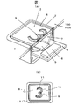
先ず、図1を参照して、第1の実施の形態に係るエレベータの操作盤に採用される文字板の概要を説明する。図1は、第1の実施の形態に係る操作スイッチの構造図であり、(a)図が部分断面を含む操作スイッチの斜視図、(b)図は操作スイッチの平面図を示している。
【0012】
図1において、符号1で総括的に示すのは、この実施の形態に係る操作盤用の操作スイッチである。この操作スイッチ1は、操作盤100に形成される複数の開口部101に取り付けられ、エレベータ150の運転に関する特定の操作指示、例えば、各階の停止や扉の開閉等を指示するためのものである。
【0013】
前記操作スイッチ1は、前記開口部101に嵌合して取り付けられるボタンケース2と、前記ボタンケース2内に出没可能に取り付けられる押圧部3と、前記押圧部3の下方に配置されるスイッチ基板4と、前記押圧部3の下方のスイッチ基板4上に配置される発光部5と、前記発光部5の周囲の前記スイッチ基板4上に配置されるスイッチ素子6と、前記押圧部3に受ける応力を前記スイッチ素子6に伝達するとともに、前記発光部5の光を前記開口部101側に反射するように配置される反射板7と、前記押圧部3と前記スイッチ基板4を離す方向に作用する図示しないバネとを含んで構成される。
【0014】
また、前記押圧部3は、その上面に略フラットな文字表示面8を備えるとともに、通常の状態において、この文字表示面8が前記操作基盤面100aと略面一となるように配置され、この文字表示面8を使用者が指などで前記ボタンケース2内に押し込むことにより、この文字表示面8を備える前記押圧部3が前記反射板7を介して前記スイッチ素子6をOFF状態からON状態に操作することができる。このON状態においては、前記発光部5が点灯状態となる。
【0015】
ここで、前記文字表示面8は、アクリル材料などの透光性を有する樹脂材料で形成される。前記文字表示面8には、この文字表示面8より隆起して形成または配置される凸文字9が設けられる。この凸文字9は前記周囲の文字表示面8と透過度の異なる材料または透過度を異なるようにする塗装や表面処理あるいはシート等が付される。
【0016】
このため、前記ON状態において、前記発行部5が点灯すると、前記凸文字9が周囲の透光性のある文字表示面8に対して光を遮蔽するので、この凸文字9が前記文字表示面8上に浮きあがって、ON状態であることを明確に識別させることができる。
【0017】
また、この実施の形態の最も大きな特徴は、前記凸文字9の断面形状を略台形状に形成している点である。即ち、この実施の形態では、前記凸文字9のベース面10(前記台形状の底辺)より、トップ面11(前記台形状の上面)を小さく形成する。これにより、健常者が視覚的にこの凸文字9を認識する場合には、広い面積を備える前記ベース面10により、この凸文字9を認識させることができる。一方、視覚障害者が指などでこの凸文字9を接触的に認識する場合は、小さな面積を備える前記トップ面11により、この凸文字9を認識させることができる。
【0018】
この種の設備機器においては、使用者に前記凸文字9を認識しやすくさせるためには、可能な範囲で大きく形成することが望ましい。例えば、エレベータにおいては、かご内のどこからでも前記凸文字9を認識できる程度の大きさの文字であることが望まれる。もちろん、複数の操作スイッチ1を備えるエレベータの操作盤100においては、大きければ良いというものではなく、装置全体の小型化を考慮する必要がある。
【0019】
例えば、米国のエレベータの規格においては、操作盤100に使われる文字の高さ寸法H0を15mm以上とすることが規定されている。しかし一方では、これらの公共性の強い設備機器においては、視覚障害者への配慮が必要である。一般に、これら設備機器においては、点字を併用しているが、文字自体を隆起させた凸文字を採用することも視覚障害者の指による触覚認識に大いに役立たせることができる。しかし、この凸文字は、触覚面積(接触面積)が大きすぎると指による触覚認識がしづらくなる課題がある。
【0020】
この実施の形態では、前記凸文字9の断面形状を前記ベース面10からトップ面11へ先細りとすることにより、視認性と触覚(接触)による認識性を向上させることができる。
【0021】
以下、図2から図5を参照して、更に詳細にこの実施の形態に係る操作スイッチ1を説明する。先ず、図2を参照して、この操作スイッチ1が採用されるエレベータの操作盤の概略構造を説明する。図2はエレベータの外観図を示すものであり、(a)図が扉と対向する壁面を取り除いてかご内をみた室内外観図、(b)図が第1操作盤の正面拡大図、(c)図が第2操作盤の正面拡大図である。
【0022】
図2において、符号150で示すエレベータのかごは、立方体形状の室内を備え、その周側面の一方に出入口151が設けられている。この出入口151を構成する壁面の一方に第1操作盤152が設けられており、第1操作盤は主として立ち姿勢での操作に使用される。また、前記出入口151を備えた周側面と隣接する両周側面には手すり153と第2操作盤154が設けられる。第2操作盤は主として車いす利用者による操作を目的としている。更に、天井面には照明装置159が設けられている。
【0023】
前記第1操作盤152は、立ち姿勢の利用者に合わせて、壁面の比較的高い位置に縦長に形成される。第1操作盤152は、その中央に階表示用の複数の操作スイッチ1が配置され、その上部にスピーカ155と非常通話用操作スイッチ156が配置される。この実施の形態では、前記階表示用の複数の操作スイッチ1は、階表示用として2列の操作スイッチ1を設け、その下方に一対の開閉用の操作スイッチ157を備えている。
【0024】
また、前記第2操作盤154は、立ち姿勢の腰位置近傍に設けられ、やや横長の正面形状を備えている。この実施の形態では、前記第2操作盤154の下側に2段の階表示用の複数の操作スイッチ1を備え、上側の一方の片側にスピーカ155と非常通話用操作スイッチ156を設け、上側の他の片側に表示部158と一対の開閉ボタン157を配置している。この実施の形態では、階表示用、開閉用、非常通話用の各操作スイッチ1に対して図1で説明した凸文字9を付している。
【0025】
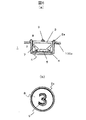
次に、図3から図5を参照して、凸文字の形状を更に詳細に説明する。図3は、凸文字「4」の具体的形状を示す説明図であり、(a)図が正面図、(b)図が断面図である。図4および図5は文字例を示すものであり、図4が数値の事例、図5がアルファベットの一例を示している。
【0026】
図3において、この実施の形態では、前記凸文字9が前記トップ面11の両側に傾斜面12を備えて前記ベース面10に連続するように形成される。そして、このトップ面11は略同一幅に形成されるので、指でこのトップ面11をなぞった際に、幅方向の凹凸感がないので触覚(接触)での認識性を向上させることができる。また、この実施の形態では、前記トップ面11が前記ベース面10の幅方向の中央に位置しているので、視覚で認識した場合に、前記トップ面11が前記ベース面10に重なって見える(斜め方向から見る)ことが軽減され、そのままベース面10を見ることができるから、視認性を向上することができる。更に、きれいな文字に仕上げることができる。
【0027】
また、この凸文字9は、前記文字表示面8から突出寸法T0張り出して形成され、ベース面10の文字幅L0、トップ面11の文字幅L1に設定されている。更に、凸文字9の高さをH0、前記傾斜面12の角度をΘに設定している。ここで、この実施の形態では、前記と凸文字9の高さH0を15mmに設定し、前記トップ面11の文字幅L1を0.8mmに設定し、更に前記傾斜面12の角度Θを45度に設定している。更にまた、前記トップ面11を前記ベース面10の文字幅に対して左右方向に同幅の傾斜面12を形成している。これにより、視覚障害者が指での触りをなるべく均等にすることで触覚感を向上させ、更に見た目の精度感を向上して視覚性を向上させている。
【0028】
更に、この実施の形態では、凸文字9の端部13以外の傾斜面12aの傾斜面幅Z1を略均等にするとともに、凸文字9の端部13の傾斜面12bの傾斜面幅Z0を他の傾斜面幅Z1より小さく(前記角度Θを45度より大きく)形成することで、凸文字9の終わり(端部13)であることを触覚的に認識しやすくするとともに、視覚的にも凸文字9にアクセントを持たせて視認性を向上させている。
【0029】
なお、この実施の形態ではΘは45度としたが、実施の形態としてΘが45度より大きい形態、例えば突出寸法T0が1.73mm、傾斜面幅Z1が略1mm、トップ面11の文字幅L1が1mmで、傾斜面の角度Θが60度という形態とすることでより効果を奏することが可能である。
図4において、前記凸文字9の前記傾斜面幅Z0は文字によってのその幅を変化させる。例えば、「1」の場合は、上部左側の筆の入り部分14は、「7」と区別するためにトップ面11は設けず、視認性を向上させるためにベース面10のみ設けるようにする。また、「2」「5」「7」「8」については、前記「4」と同様な手法で端部13を形成する。また、「3」の中央左側のおり返し部分15については傾斜面幅Z2を1.5mmとして大きく形成し、同様に、「6」の右上の筆入り部分16、及び、「9」のおり返し部分17については、他の傾斜面幅Z1より大きいZ3(0.8mm)に設定することで、視認性と触覚による識別性を向上させている。「0」「8」は端部13が無いので略均等の傾斜面幅Z1とする。
【0030】
図5に示すアルフアベッドについては、例えば、角のある端部を備えた「P」「R」「L」「M」については、前記「4」と同様に手法で端部13を形成する。一方、「G」の両端部18については、「6」と同様な手法で形成する。更に「B」は端部13がないので略同様な傾斜面12の幅で形成する。
【0031】
このように、この実施の形態に係る凸文字9は、H0が15mm以上で、T0が1mm以上の時に有効である。しかし、H0及びT0が前記設定より大きいからと言って上限がある。この上限は、実験的見地から、前記L1が0.5mmより大きく、1.5mmより小さく設定すると触覚による識別が良好である。特に、前記L1が0.6mm ≦ L1 1.2mm、あるいは、0.7mm ≦ L1 0.9mmであればいっそう識別が容易となる。図3の(b)図で示したトップ面11と傾斜面12との稜線(角R)は、エッジを立てる(角Rを小さくする)ことでトップ面11を触覚での識別をし易くすることができる。しかし、必ずしも前記稜線(角R)を小さくする必要はなく、この角Rを大きくしてもトップ面11の連続感を得るようにすれば同様な効果を得ることができる。
【0032】
このことから、前記トップ面11の面積Q1は、前記ベース面10の面積Q2より小さく、より具体的には面積Q1を面積Q2で割った値が0.5より小さければ、より視認性と触覚により識別性を向上させることができる。
【0033】
更にこの実施の形態に係る凸文字9では、トップ面の文字幅L1がベース面の文字幅L0よりも狭くなっているので、「3」と「8」の触覚における識別時において、「3」の開いている部分の開き幅が大きくなる点でも識別性を向上させることができる。
【0034】
図6は、前記第1の実施の形態の他の応用例を示し、(a)図は操作スイッチ1の断面図、(b)図は正面図を示している。図6において、この実施の形態では、前記押圧部3の周囲を囲むボタンケース2の周囲枠体2aを前記操作基盤面100aより張り出して形成するとともに、前記文字表示面8を前記周囲枠体2aより落ち込んで形成する。そして、操作スイッチ1の形状を円形に形成する。
【0035】
この実施の形態によれば、触覚での識別に対し、前記周囲枠体2aにより明確に操作スイッチ1の所在を識別することができる。しかも、文字表示面8は前記周囲枠体2aより奥まって形成されるので、誤操作を軽減することができる。したがって、このような操作スイッチ1は、第2操作盤154に適している。なお、操作スイッチ1の形状を円形とし、かつ文字表示面8を奥まって形成することで、指のフイット感を向上させることができる。そして、この実施の形態の操作スイッチ1において、前記凸文字9を設けることにより、前記周囲枠体2a内の文字を1つの文字として視認性と触覚による識別性を向上させることができる。
【0036】
また、図7は、凸文字9の製造方法に関する他の実施の形態である。図7は操作スイッチの部分断面図である。図7において、前記図1から図6の実施の形態では、凸文字9を前記周囲の文字表示面8と透過度の異なる材料または透過度を異なるようにする塗装や表面処理あるいはシート等が付されると説明したが、図7の(a)図の実施の形態は、前記透明な文字表示面8に不透明な材料で形成される凸文字9を形成した実施の形態である。この実施の形態では、発光部5からの光が前記不透明な凸文字9のベース面10に反射し、この凸文字9以外の文字表示面8では透過するので、前記凸文字9の視認性を向上させることができる。また、この実施の形態において、前記凸文字9と文字表示面8との間に不透明な図示しないシートを貼り付けることで、前記不透明な凸文字9と同様な効果を得ることができる。また、前記凸文字を色付きの透明材料で形成したり、あるいは色付きの透明シートとすることで、色彩による識別効果を得ることができる。
【0037】
また(b)図に示すように、前記押圧部3を不透明な材料で形成し、この文字表示面8に文字をくりぬいて、このくりぬいた部分に透明材料で形成される凸文字9を嵌合することにより、凸文字9の部分を光で浮き上がらせて視認性を向上させることができる。
【0038】
なお、この実施の形態でも、透明と不透明の部分を反転して形成しても良い。また、色付きの透明材料で識別感を違わせて形成しても同様な作用効果を得ることができる。更に、凸文字9と文字表示面8を透光性のある同一材料で形成し、その表面に凸文字8を非透光性、あるいは反転して透光性のある印刷が施されたシートを貼り付けたり、あるいは一体成型することで、前記のような同様な作用効果を得るようにしてもよい。
【0039】
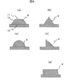
次に、図8は凸文字の断面形状を説明するものである。(a)図がこの実施の形態に係る図1の断面図、(b)図が正三角形状の断面を備えた凸文字、(c)図が円弧形状の断面を備えた凸文字、(d)図が偏った傾斜面を備えた凸文字、(e)図が従来の断面形状を備えた凸文字を示している。
【0040】
この実施の形態では、前記したように、前記凸文字9の断面形状を前記ベース面10からトップ面11へ先細りとすることで、本発明の効果が達成される。したがって、(a)図から(d)図に示す凸文字9でも同様な効果を得ることができる。しかし、(b)図の正三角形の断面を持つ凸文字9では、指に線として認識されるので、触覚での認識が落ち、しかも、視覚的にも傾斜面の光の反射が単純になるので視認性でも(a)図よりも効果が落ちる。また、(c)図の弧状の断面形状の凸文字9は、指に柔らかな感触で受け止められるので触覚による識別はやや(a)図より落ちるが同様な効果を得ることができる。しかし、視覚的には柔らかな文字表現となりシャープな文字表現に劣る。また、(d)図の偏った傾斜面を備えた凸文字9では、(b)図と同様な欠点があり、視覚的にも多様な表現を行うことがし難い。
【0041】
更に、(e)図では、従来例の凸文字の断面形状をやや誇張して示している。従来の凸文字9’は、1mm程度の突出寸法の場合は抜きテーパを付けなくとも成形できる。このため、傾斜面を付ける必要がない。(e)図は抜きテーパを誇張して図示しているが、このような突出寸法が小さいと抜きテーパはほとんど識別できない程度のものとなる。この発明では、この(e)図に示す従来の凸文字9’の断面形状とは明確に認識可能な、あるいは意識して形成される傾斜面12を備えている。これにより、前記したような作用効果を得ることができる。
【0042】
次に、図9、図10は他の分野に前記凸文字9を応用したものである。図9は大型の操作キーを備えた電子卓上計算機に採用した外観図、図10は電車の出入口に号車番号を表したものである。
【0043】
図9において、近年、各機器においては、大きな操作キー201を備えた機器が多くなっている。図9に示すのは、複数の大きな操作キー201を備えた電子卓上計算機200を示している。この電子卓上計算機200によれば、大きな操作キー201により数値を入力して、その結果を大型表示部202に表示することができる。このような大型の操作キー201に前記凸文字9をキー表面に設けることで前記エレベータの操作キーと同様な作用効果を得ることができる。
【0044】
また、図10は、電車300の出入口301の近傍に凸文字9による号車番号302を付したものである。この事例では、電車300への応用例を示したが、同様な作用効果は、部屋の番号や廊下の壁面に掲示される案内盤でも採用することができる。
【0045】
【発明の効果】
本発明によれば、視認性が良好で、かつ、指などによる触覚での認識が良好な文字を利用した操作盤を提供することができる。
【図面の簡単な説明】
【図1】第1の実施の形態に係る操作スイッチの構造図である。
【図2】第1の実施の形態に係るエレベータかご内装の外観図である。
【図3】凸文字「4」の具体的形状を示す説明図である。
【図4】数値の凸文字の例を表す図である。
【図5】アルファベットの凸文字の一例を表す図である。
【図6】第1の実施の形態の他の応用例を示す図である。
【図7】凸文字の製造方法に関する他の実施の形態を示す図である。
【図8】凸文字の断面形状を説明する図である。
【図9】操作キーに凸文字を採用した電子卓上計算機の外観図である。
【図10】号車番号表示に凸文字を採用した電車の客車出入口付近の外観図である。
【符号の説明】
1…操作スイッチ、2…ボタンケース、3…押圧部、4…スイッチ基板、5…発光部、6…スイッチ素子、7…反射板、8…文字表示面、9…凸文字、10…ベース面、11…トップ面、12…傾斜面、12a、12b…傾斜面、13…端部、14…筆の入り部分、15…おり返し部分、16…筆入り部分、17…おり返し部分、18…端部、150…エレベータのかご、100…操作盤、100a…操作基盤面、101…開口部、150…エレベータ、151…出入口、152…第1操作盤、153…手すり、154…第2操作盤、155…スピーカ、156…非常通話用操作スイッチ、157…一対の開閉ボタン、158…表示部、159…照明装置、Z0…凸文字の端部の傾斜面幅、Z1…凸文字の端部以外の傾斜面幅、H0…凸文字の高さ、T0…凸文字の突出寸法、L0…ベース面の文字幅、L1…トップ面の文字幅、R…トップ面と傾斜面との稜線(角)、Q1…トップ面の面積、Q2…ベース面の面積。[0001]
BACKGROUND OF THE INVENTION
The present invention relates to a dial plate that has good visibility for healthy people and good tactile recognition by a finger or the like for visually handicapped people, and particularly relates to a dial plate used for an operation panel such as an elevator. Is.
[0002]
[Prior art]
Conventionally, operation panels that are easy to use for all users have been indispensable for operation panels used for various public equipment. For example, a floor display button employed in an operation panel of an elevator is required to display characters with good visibility for a healthy person and good tactile recognition with a finger or the like for a visually impaired person.
[0003]
In the prior art, a technique is widely used in which convex characters (including codes) are provided at specific locations of a container and the item of the container is recognized by tactile recognition using a finger or the like.
[0004]
Moreover, in public equipment, in order to solve the above-mentioned problem, the unevenness of the operation button used on the operation panel is devised, or the character is raised from the surrounding button surface by about 1 mm. Those using letters in combination are known.
[0005]
Examples of the prior art include Japanese Patent Application Laid-Open No. 2001-247153 and Japanese Patent Application Laid-Open No. 8-73145.
[0006]
[Problems to be solved by the invention]
In the field of the elevator, in the United States, for the convenience of the visually impaired, it is stipulated that floor numbers made up of convex characters having a character height of 15 mm or more are arranged beside the buttons on the operation panel. (ADA method). Needless to say, in order to improve the visibility, the character height is better as the height of the character is larger than 15 mm.
However, when the line width of the protruding portion of the convex character increases in proportion to the height of the convex character, there is a problem that it becomes difficult to recognize with a tactile sensation with a finger or the like.
[0007]
Accordingly, an object of the present invention is to provide an operation panel that uses characters with good visibility and good tactile recognition with a finger or the like.
[0008]
[Means for Solving the Problems]
In the operation panel of the present invention, in order to solve the problem, a convex character portion protruding from the character display surface is formed, and the character width of the base surface of the character portion on the character display surface side is set to the character portion. It is made larger than the character width of the top surface formed in the top part of.
[0009]
DETAILED DESCRIPTION OF THE INVENTION
Hereinafter, an embodiment according to the present invention will be described in detail with reference to FIGS. In addition, the same site | part, an arrow, a direction, etc. are shown with the same code | symbol etc., and the overlapping description is abbreviate | omitted.
[0010]
1 to 8 show an operation panel of an elevator according to the first embodiment, and FIGS. 9 and 10 show other application examples.
[0011]
First, with reference to FIG. 1, an outline of a dial plate employed in the operation panel of the elevator according to the first embodiment will be described. 1A and 1B are structural diagrams of an operation switch according to the first embodiment, in which FIG. 1A is a perspective view of the operation switch including a partial cross section, and FIG. 1B is a plan view of the operation switch.
[0012]
In FIG. 1,
[0013]
The
[0014]
The
[0015]
Here, the
[0016]
For this reason, when the issuing
[0017]
The most significant feature of this embodiment is that the cross-sectional shape of the
[0018]
In this kind of equipment, in order to make it easy for the user to recognize the
[0019]
For example, the standard for elevators in the United States stipulates that the height H0 of characters used for the
[0020]
In this embodiment, by making the cross-sectional shape of the
[0021]
Hereinafter, the
[0022]
In FIG. 2, an elevator car denoted by
[0023]
The
[0024]
The
[0025]
Next, the shape of the convex character will be described in more detail with reference to FIGS. FIGS. 3A and 3B are explanatory diagrams showing a specific shape of the convex character “4”, in which FIG. 3A is a front view and FIG. 3B is a cross-sectional view. 4 and 5 show examples of characters. FIG. 4 shows an example of numerical values, and FIG. 5 shows an example of alphabets.
[0026]
In FIG. 3, in this embodiment, the
[0027]
The
[0028]
Furthermore, in this embodiment, the inclined surface width Z1 of the inclined surface 12a other than the
[0029]
In this embodiment, Θ is 45 degrees. However, in the embodiment, Θ is larger than 45 degrees, for example, the protrusion dimension T0 is 1.73 mm, the inclined surface width Z1 is approximately 1 mm, and the character width of the
In FIG. 4, the inclined surface width Z0 of the
[0030]
For the alpha bed shown in FIG. 5, for example, for “P”, “R”, “L”, and “M” with cornered end portions, the
[0031]
Thus, the
[0032]
Therefore, the area Q1 of the
[0033]
Furthermore, in the
[0034]
6A and 6B show another application example of the first embodiment, in which FIG. 6A is a sectional view of the
[0035]
According to this embodiment, the location of the
[0036]
FIG. 7 shows another embodiment relating to the method of manufacturing the
[0037]
Further, as shown in FIG. 5B, the
[0038]
In this embodiment, the transparent and opaque portions may be reversed. Moreover, the same effect can be obtained even if it is formed with a colored transparent material with a different feeling of discrimination. Further, the
[0039]
Next, FIG. 8 explains the cross-sectional shape of the convex character. 1A is a cross-sectional view of FIG. 1 according to this embodiment, FIG. 1B is a convex character having a regular triangular cross section, FIG. 2C is a convex character having an arc-shaped cross section, (d) ) A convex character having an inclined surface with a biased figure, and (e) a convex character having a conventional cross-sectional shape.
[0040]
In this embodiment, as described above, the effect of the present invention is achieved by tapering the cross-sectional shape of the
[0041]
Further, in FIG. 5E, the cross-sectional shape of the convex character of the conventional example is slightly exaggerated. The conventional convex character 9 'can be formed without a taper when the protruding dimension is about 1 mm. For this reason, it is not necessary to attach an inclined surface. (E) The drawing shows the drawing taper in an exaggerated manner. However, when such a protruding dimension is small, the drawing taper is almost indistinguishable. The present invention includes an
[0042]
Next, FIGS. 9 and 10 show the application of the
[0043]
In FIG. 9, in recent years, the number of devices having
[0044]
Further, FIG. 10 shows a case where a
[0045]
【The invention's effect】
According to the present invention, it is possible to provide an operation panel using characters with good visibility and good tactile recognition with a finger or the like.
[Brief description of the drawings]
FIG. 1 is a structural diagram of an operation switch according to a first embodiment.
FIG. 2 is an external view of the elevator car interior according to the first embodiment.
FIG. 3 is an explanatory diagram showing a specific shape of a convex character “4”.
FIG. 4 is a diagram illustrating an example of a numerical convex character.
FIG. 5 is a diagram illustrating an example of a convex character of an alphabet.
FIG. 6 is a diagram illustrating another application example of the first embodiment.
FIG. 7 is a diagram showing another embodiment relating to a method for producing convex characters.
FIG. 8 is a diagram illustrating a cross-sectional shape of a convex character.
FIG. 9 is an external view of an electronic desk calculator that employs convex characters as operation keys.
FIG. 10 is an external view of the vicinity of a passenger car entrance and exit of a train adopting convex characters for displaying a car number.
[Explanation of symbols]
DESCRIPTION OF
Claims (2)
前記ボタンケースから露出する前記押圧部には文字表示面が形成され、
前記文字表示面には、この文字表示面から突出する文字部が形成され、
前記文字部は、
前記文字部の前記文字表示面側に形成されるベース面と、
前記文字部の最頂部に形成されるトップ面と、
前記ベース面と前記トップ面の間に形成される傾斜面を有し、
前記文字部の断面は前記トップ面側にかけて先細りの断面である
ことを特徴とするエレベーター用操作盤。A button case fitted and attached to the opening of the operation panel, a pressing part attached so as to be able to appear and retract in the button case, a switch board disposed below the pressing part, and a switch below the pressing part A light emitting unit disposed on the substrate, a switch element disposed on the switch substrate around the light emitting unit, and a stress applied to the pressing unit are transmitted to the switch element, and light from the light emitting unit is transmitted to the switch element. An operation panel comprising a plurality of operation switches configured to include a reflecting plate arranged to reflect on the opening side, and a spring acting in a direction separating the pressing portion and the switch substrate,
A character display surface is formed on the pressing portion exposed from the button case,
A character portion protruding from the character display surface is formed on the character display surface,
The character part is
A base surface formed on the character display surface side of the character portion;
A top surface formed at the top of the character portion;
Having an inclined surface formed between the base surface and the top surface;
The elevator operation panel characterized in that the cross section of the character portion is a tapered cross section toward the top surface side.
前記文字表示面は透光性素材で形成され、前記文字部は非透光性素材で形成されている
ことを特徴とするエレベーター用操作盤。The operation panel according to claim 1,
The operation panel for an elevator, wherein the character display surface is formed of a translucent material, and the character portion is formed of a non-translucent material.
Priority Applications (1)
| Application Number | Priority Date | Filing Date | Title |
|---|---|---|---|
| JP2001382471A JP3722061B2 (en) | 2001-12-17 | 2001-12-17 | Character display board with convex characters and its operation panel |
Applications Claiming Priority (1)
| Application Number | Priority Date | Filing Date | Title |
|---|---|---|---|
| JP2001382471A JP3722061B2 (en) | 2001-12-17 | 2001-12-17 | Character display board with convex characters and its operation panel |
Related Child Applications (1)
| Application Number | Title | Priority Date | Filing Date |
|---|---|---|---|
| JP2004329944A Division JP4123222B2 (en) | 2004-11-15 | 2004-11-15 | Elevator control panel |
Publications (3)
| Publication Number | Publication Date |
|---|---|
| JP2003186408A JP2003186408A (en) | 2003-07-04 |
| JP2003186408A5 JP2003186408A5 (en) | 2004-09-24 |
| JP3722061B2 true JP3722061B2 (en) | 2005-11-30 |
Family
ID=27592801
Family Applications (1)
| Application Number | Title | Priority Date | Filing Date |
|---|---|---|---|
| JP2001382471A Expired - Fee Related JP3722061B2 (en) | 2001-12-17 | 2001-12-17 | Character display board with convex characters and its operation panel |
Country Status (1)
| Country | Link |
|---|---|
| JP (1) | JP3722061B2 (en) |
Families Citing this family (5)
| Publication number | Priority date | Publication date | Assignee | Title |
|---|---|---|---|---|
| JP2006232454A (en) * | 2005-02-23 | 2006-09-07 | Matsushita Electric Works Ltd | Elevator pushbutton device |
| JP5105606B2 (en) * | 2008-01-22 | 2012-12-26 | ジャパンライフ株式会社 | Spacer with display |
| JP5694656B2 (en) * | 2009-10-27 | 2015-04-01 | 株式会社木村技研 | Toilet facilities |
| CN102741960B (en) | 2010-03-24 | 2015-08-19 | 三菱电机株式会社 | The manufacture method of the button with raised character |
| JP6723361B2 (en) * | 2016-08-01 | 2020-07-15 | 三菱電機株式会社 | Elevator operation buttons and manufacturing method thereof |
-
2001
- 2001-12-17 JP JP2001382471A patent/JP3722061B2/en not_active Expired - Fee Related
Also Published As
| Publication number | Publication date |
|---|---|
| JP2003186408A (en) | 2003-07-04 |
Similar Documents
| Publication | Publication Date | Title |
|---|---|---|
| EP2159183B1 (en) | Elevator destination floor registration device | |
| US7113177B2 (en) | Touch-sensitive display with tactile feedback | |
| TW200304423A (en) | Operating button device | |
| CN109869066B (en) | Toilet door opening/closing switch and toilet automatic door system | |
| JP3722061B2 (en) | Character display board with convex characters and its operation panel | |
| TW201530588A (en) | Luminous keyboard | |
| JP4123222B2 (en) | Elevator control panel | |
| US5390766A (en) | Indicator panel for elevator cars having an emergency calling device door handle with information and operating aids | |
| JP2007314300A (en) | Operation panel for elevator | |
| JPH07319623A (en) | Touch panel type liquid crystal display | |
| JP2003203535A (en) | Operation button | |
| JP4226921B2 (en) | Elevator operation panel | |
| JP4381633B2 (en) | Elevator operation panel | |
| JP2000226162A (en) | Elevator call operation device and elevator system equipped therewith | |
| JP5625528B2 (en) | Elevator operation button device | |
| CN2435784Y (en) | Luminous computer keyboard key | |
| JP2003263936A (en) | Operation button | |
| JP2002149094A (en) | Display | |
| KR101598801B1 (en) | Touching map production method for the blind and its touching map | |
| JP4855266B2 (en) | Elevator hall button device | |
| JP2003186408A5 (en) | ||
| CN2441173Y (en) | luminous computer keyboard buttons | |
| JP2001299646A (en) | Operation plate for toilet | |
| JPH08185124A (en) | Braille touch guide board | |
| JPH07181887A (en) | Braille guide plate |
Legal Events
| Date | Code | Title | Description |
|---|---|---|---|
| A977 | Report on retrieval |
Free format text: JAPANESE INTERMEDIATE CODE: A971007 Effective date: 20040831 |
|
| A131 | Notification of reasons for refusal |
Free format text: JAPANESE INTERMEDIATE CODE: A131 Effective date: 20040914 |
|
| A521 | Request for written amendment filed |
Free format text: JAPANESE INTERMEDIATE CODE: A523 Effective date: 20041115 |
|
| TRDD | Decision of grant or rejection written | ||
| A01 | Written decision to grant a patent or to grant a registration (utility model) |
Free format text: JAPANESE INTERMEDIATE CODE: A01 Effective date: 20050823 |
|
| A61 | First payment of annual fees (during grant procedure) |
Free format text: JAPANESE INTERMEDIATE CODE: A61 Effective date: 20050905 |
|
| R151 | Written notification of patent or utility model registration |
Ref document number: 3722061 Country of ref document: JP Free format text: JAPANESE INTERMEDIATE CODE: R151 |
|
| FPAY | Renewal fee payment (event date is renewal date of database) |
Free format text: PAYMENT UNTIL: 20080922 Year of fee payment: 3 |
|
| FPAY | Renewal fee payment (event date is renewal date of database) |
Free format text: PAYMENT UNTIL: 20090922 Year of fee payment: 4 |
|
| FPAY | Renewal fee payment (event date is renewal date of database) |
Free format text: PAYMENT UNTIL: 20090922 Year of fee payment: 4 |
|
| FPAY | Renewal fee payment (event date is renewal date of database) |
Free format text: PAYMENT UNTIL: 20100922 Year of fee payment: 5 |
|
| FPAY | Renewal fee payment (event date is renewal date of database) |
Free format text: PAYMENT UNTIL: 20100922 Year of fee payment: 5 |
|
| FPAY | Renewal fee payment (event date is renewal date of database) |
Free format text: PAYMENT UNTIL: 20110922 Year of fee payment: 6 |
|
| FPAY | Renewal fee payment (event date is renewal date of database) |
Free format text: PAYMENT UNTIL: 20120922 Year of fee payment: 7 |
|
| FPAY | Renewal fee payment (event date is renewal date of database) |
Free format text: PAYMENT UNTIL: 20120922 Year of fee payment: 7 |
|
| FPAY | Renewal fee payment (event date is renewal date of database) |
Free format text: PAYMENT UNTIL: 20130922 Year of fee payment: 8 |
|
| LAPS | Cancellation because of no payment of annual fees |