JP3721884B2 - Fixing apparatus and image forming apparatus - Google Patents
Fixing apparatus and image forming apparatus Download PDFInfo
- Publication number
- JP3721884B2 JP3721884B2 JP26960999A JP26960999A JP3721884B2 JP 3721884 B2 JP3721884 B2 JP 3721884B2 JP 26960999 A JP26960999 A JP 26960999A JP 26960999 A JP26960999 A JP 26960999A JP 3721884 B2 JP3721884 B2 JP 3721884B2
- Authority
- JP
- Japan
- Prior art keywords
- fixing
- fixing belt
- roller
- transfer material
- pressure
- Prior art date
- Legal status (The legal status is an assumption and is not a legal conclusion. Google has not performed a legal analysis and makes no representation as to the accuracy of the status listed.)
- Expired - Fee Related
Links
Images


Landscapes
- Fixing For Electrophotography (AREA)
- Rolls And Other Rotary Bodies (AREA)
Description
【0001】
【発明の属する技術分野】
本発明は、電子写真式画像形成装置のベルト式定着装置に関するものである。
【0002】
【従来の技術】
従来、電子写真式画像形成装置に用いられている定着装置は、所定の温度に維持された加熱ローラと、弾性層を有してその加熱ローラに圧接する加圧ローラとによって、未定着のトナー画像が形成された記録材を挟持搬送しつつ加熱する熱ローラ定着方式が多用されている。
【0003】
しかしながら、この種の装置では、加熱ローラの熱容量が大きくなりウォーミングアップ時間が長くなるとともに、弾性層内側の温度が高くなり、ローラの寿命を短くしていた。
【0004】
また、カラー画像ではベタ面積が大きい画像が多く、そのベタ画像も黒以外ののものが多くて光沢むらなどが目立つ。上記の加熱及び加圧ローラにハードローラを用いる場合は、紙やトナー層の凹凸に応じた光沢のむらが生じるため、画像品位が低下するという問題点があった。
【0005】
【発明が解決しようとする課題】
前記問題点を解決するために、ゴムローラやゴムベルトを用いた定着方式が提案されている。
【0006】
ゴムローラを用いると良好な画像品位を得ることができるが、ウォーミングアップに時間がかかり、ローラの寿命が短いなどの不具合があり、この不具合は複写機やプリンタの高速化に伴って、ますます顕著になってきている。
【0007】
定着ベルトを用いた定着装置には以下の課題がある。
【0008】
(1)定着用のゴムベルトを用いて張力をかけた方式では、ベルトが片寄ろうとする力が大きく、この対策のためにユニットのコストが高くなり信頼性も必ずしも高くない。
【0009】
(2)複数の支持ローラに懸架された定着ベルトを加熱手段により加熱して定着する定着装置では、加熱された加熱ローラから支持ローラとの接触面に熱が逃げ、ウォーミングアップ時間を長くしていた。
【0010】
(3)支持ローラと定着ベルトとの接触面積を小さくするために、支持ローラ表面に、回転軸に平行する突起条を形成すると、支持ローラと定着ベルトと断続接触により騒音を発生する。
【0011】
(4)定着ベルトを用いた定着装置においては、画像領域で定着ベルトの温度を検知して温度制御する必要があるが、定着ベルトの外周面に温度センサを設置すると、定着ベルトの表面に生じた微少な傷が画像不良を引き起こすため、非画像領域に温度センサを設置する必要があった。非画像領域は転写材に熱を奪われることはなく、転写材に熱を奪われる画像領域とは温度が異なるため、定着に最適な温度に制御する事は困難であった。
【0012】
(5)また、定着ベルトの外周面に温度センサを設置すると、定着ベルトの表面に付着したトナーや紙粉が、温度検知不良を発生させる。
【0013】
(6)定着ベルトを加熱する加熱手段を、定着ベルトの外周面に対向して設置すると、加熱手段が露出し、安全操作上から好ましくなく、更に、加圧ローラに搬入される転写材に近接して、過熱されるおそれがある。
【0014】
本発明の目的は、上記課題を解決し、ウォーミングアップ時間の短縮、定着ベルトの温度検知精度向上、高速定着及び高画質の定着が可能で、安全化、静音化と寿命の長い定着装置及び該定着装置を備えた画像形成装置を提案することを目的とする。
【0015】
【課題を解決するための手段】
【0016】
本発明の定着装置は、トナー像を担持する転写材を加熱加圧により定着する定着装置において、少なくとも2本の支持ローラに巻回されて回動可能な定着ベルトと、前記定着ベルトを加熱する加熱手段と、前記定着ベルトと定着する前記転写材とを重ねた状態で挟持搬送して加熱加圧することにより前記トナー像を担持する転写材を定着する少なくとも2本の加圧ローラと、を備え、前記定着ベルトに内接する前記支持ローラの回転軸の周囲を、気体層を介して密閉する中空円筒状の袋体となし、該袋体の内部圧力を、大気圧より高くしたことを特徴とするものである(請求項1)。
【0018】
本発明の画像形成装置は、前記請求項1〜5の何れか1項に記載の定着ベルト、加熱手段、加圧ローラ、温度センサから成る定着装置を備えて成ることを特徴とするものである(請求項6)。
【0019】
【発明の実施の形態】
以下、本発明の定着装置及び該定着装置を搭載した画像形成装置を図面によって説明する。
【0020】
図1は、本発明の定着装置を搭載した画像形成装置であるカラープリンタを示す断面構成図である。
【0021】
このカラープリンタは、像担持体である可撓性の無端ベルト状の感光体(以下、感光体と称す)1の周囲に、4組のスコロトロン帯電器(以下、帯電器と称す)2Y,2M,2C,2K、4組の像露光装置(走査光学装置)3Y,3M,3C,3K、4組の現像器4Y,4M,4C,4Kとから成る画像形成ユニット(図示の4組)を縦列に配設したものである。なお、図示の像露光装置3Y,3M,3C,3Kは、レーザビーム走査光学装置を使用したものである。
【0022】
感光体1は、駆動ローラ11及び下ローラ12、上ローラ13に張架され、テンションローラ14の作用により緊張状態にされ、内周面に設けられたバックアップ部材15により局部的に当接しながら、図示の時計方向に回動する。バックアップ部材15は、感光体1の背面に当接して、現像器4Y,4M,4C,4Kの各現像剤担持体(以下、現像スリーブと称す)41Y,41M,41C,41Kの現像領域及び像露光装置3Y,3M,3C,3Kの結像位置に感光体1を規制している。
【0023】
カラー画像形成装置に使用される二成分現像剤のトナーは、イエロー、マゼンタ、シアン等の顔料又は染料から成る着色剤及びカーボンブラック等の黒色顔料、バインダー樹脂、離型剤、荷電制御剤等等を含有する。キャリアとしては、フェライト、マグネタイト、鉄粉等の強磁性粒子を用い、望ましくは、前記強磁性粒子の表面をフッソ系、シリコーン系等の樹脂でコーティングしたものが良い。
【0024】
画像記録のスタートにより、駆動モータ(図示せず)が回動して駆動ローラ11を介して感光体1は図示の時計方向へと回動し、帯電器2Yの帯電作用により感光体1への電位の付与が開始される。感光体1は電位を付与されたあと、像露光装置3Yにおいて第1の色信号すなわちイエロー(Y)の画像信号に対応する電気信号による露光が開始され、感光体1の回動(副走査)によってその表面の感光層に現像画像のイエロー(Y)の画像に対応する静電潜像を形成する。この潜像は現像器4Yにより現像スリーブ41Y上に付着搬送された現像剤が、現像領域において非接触の状態で反転現像され、イエロー(Y)のトナー像となる。
【0025】
次いで感光体1はイエロー(Y)のトナー像の上にさらに帯電器2Mの帯電作用により電位が付与され、像露光装置3Mの第2の色信号すなわちマゼンタ(M)の画像信号に対応する電気信号による露光が行われ、現像器4Mによる非接触の反転現像によって前記のイエロー(Y)のトナー像の上にマゼンタ(M)のトナー像が重ね合わせて形成される。
【0026】
同様のプロセスにより帯電器2C、像露光装置3C及び現像器4Cによってさらに第3の色信号に対応するシアン(C)のトナー像が形成される。さらに帯電器2K、像露光装置3K及び現像器4Kによって第4の色信号に対応する黒色(K)のトナー像が順次重ね合わせて形成され、感光体1の一回転以内にその周面上にカラーのトナー像が形成される。
【0027】
現像器4Y,4M,4C,4Kによる現像作用に際しては、それぞれ現像スリーブ41Y,41M,41C,41Kに対し、感光体1の帯電と同極性の直流バイアス、あるいは直流バイアスに交流を加えた現像バイアスが印加され、現像スリーブ上に付着した二成分現像剤による非接触反転現像が行われて、導電層を接地した感光体1上の静電潜像形成部にトナーを付着させる。
【0028】
かくして、感光体1の周面上に形成されたカラーのトナー像は、帯電器2Fによって付着トナーの電位が揃えられたのち転写領域に至る。給紙装置5の給紙カセット51或いは手差し給紙台53から、それぞれ給紙手段52,54により送り出され、レジストローラ対55へと搬送された転写材Pは、レジストローラ対55の駆動によって感光体1上のトナー像領域通過と同期して給紙され、感光体1の駆動用の駆動ローラ11の下部に対向して配置された転写ローラ等の転写手段6によりトナー像が転写される。
【0029】
トナー像が転写された転写材Pは、駆動ローラ11の曲率に沿った感光体1周面より分離されたのち、定着装置7へ搬送される。定着装置7によりトナー像は熔融され、転写材Pに定着される。定着処理終了後の転写材Pは、排紙ローラ対81,82,83により搬送されて、上部に設けられた排紙トレイ84に転写材上のトナー像面を下面にして排出される。
【0030】
一方、転写材Pを分離した感光体1は、クリーニング装置9のクリーニングブレード91によって摺擦され、残留トナーを除去し、清掃される。なお、次の原稿画像のトナー像の形成が続いて行われるときは、帯電前除電器92による感光体1の感光体面への露光が行われて前歴の電荷の除去がなされる。
【0031】
(第1の実施の形態)
図2は、本発明の定着装置の一実施の形態を示す断面図、図3は定着装置の平面図である。
【0032】
図2において、71,72は相対的に接離可能な一対の加圧ローラ、73はエンドレスベルト状の定着ベルト、74,75は定着ベルト73を架設、支持する一対の支持ローラ、76は加熱源であるハロゲンヒータ76Aと反射板76Bとから成る加熱手段、77は定着ベルト73の外周面を清掃するクリーニング手段、78は定着ベルト73の温度を検知する温度センサである。
【0033】
一対の加圧ローラ71,72は、その少なくとも一方は回転軸位置が可動になっている。定着時には、定着ベルト73と転写材Pとを挟持圧着して搬送する。非定着時には、少なくとも一方のローラ、例えば図示の加圧ローラ72は圧接力に抗して矢示方向に移動し、加圧ローラ71から離間して間隙を形成する。
【0034】
定着ベルト73は、例えば、電鋳加工により形成されたエンドレスベルト状のNi層から成る基体の表面にシリコーンゴム層と保護層を積層したものである。
【0035】
シリコーンゴム層は、例えば厚さ0.2mm、ゴム硬度3°〜60°(JISA)の弾性を有し、熱容量の小さいベルトである。また、定着ベルト73の内周は赤外線吸収材料でコーティングされていて、照射光の吸収率が高く、ハロゲンヒータ76Aによる加熱により短時間で所定温度(例えば190℃)まで温度上昇するようになっている。
【0036】
定着ベルト73は、支持ローラ74と支持ローラ75との間に0.5kg/cm以下、更に好ましくは0.2kg/cm以下のごく弱い張力で張架されている。或いは張力ゼロの緩みをもった状態でも良い。
【0037】
定着ベルト73は、定着処理時以外の時には、支持ローラの回転により回動される。定着処理時の定着ベルト73は、加圧ローラ71,72の圧接駆動により挟持されて回動される。定着ベルト73の回動速度は、転写材Pの搬送速度と同一である。
【0038】
支持ローラ74は、図3に示すように、回転軸74Bの軸方向に対して傾斜角を有する螺旋状の突起条を形成したローラ部74A、駆動源により駆動回転される回転軸74B、ローラ部74Aの両端部に接続するフランジ部材74C、回転軸74Bの一方の軸端に固定され駆動源に接続する歯車74Dから構成されている。
【0039】
支持ローラ75は、回転軸75Bの軸方向に対して傾斜角を有する螺旋状の突起条を形成したローラ部75A、回転軸75B、ローラ部75Aの両端部に接続するフランジ部材75Cから成る。
【0040】
ローラ部74A,75Aは、加熱手段76による定着温度に対して耐熱性を有し、低熱伝導率を有する材料、例えば、発泡シリコーンゴム等で形成されている。
【0041】
ローラ部74A,75Aは、回転軸74B、75Bの外周にシリコーンゴム又は他の耐熱性樹脂を一体成型したもの、又は、金属や樹脂から成る中空円筒部材の外周面に紐状のシリコーンゴムを螺旋状に巻き付けて突起条を形成したもの等が用いられる。
【0042】
ローラ部74A,75Aには、定着ベルト73から可能な限り熱を奪わないように、定着ベルト73との接触面積を減らすため、螺旋状の突起条が形成されている。これにより、定着装置7のウォーミングアップ時には、定着ベルト73のみを加熱すればよく、従来のローラ定着方式等に比べて芯金などに奪われる熱量がないため、ウォーミングアップ時間の大幅な短縮が可能になった。また、突起部が螺旋状をなすため、定着ベルト73とローラ部74A,75Aとが連続的に接触し、定着ベルト73の動作音が軽減される。
【0043】
支持ローラ74と支持ローラ75とがともに画像形成装置本体の駆動装置により駆動される場合には、支持ローラ74のローラ部74Aに形成された螺旋状の突起条の傾斜角の方向と、支持ローラ75のローラ部75Aに形成された螺旋状の突起条の傾斜角の方向を相互に逆向きとする。螺旋状の突起条による定着ベルト73を片側に寄らせる力は、ローラ部74Aとローラ部75Aとでは互いに逆方向になり、螺旋状の突起条を設けたことによる定着ベルト73の偏りは防止される。
【0044】
支持ローラ75が定着ベルト73を介して、支持ローラ74より駆動を伝達されて回転するなど、2本の支持ローラのうち一方が定着ベルト73を介して従動で駆動される場合には、螺旋状の突起条の傾斜角方向を同じ向きにすることによって定着ベルト73を片寄らせる力の向きが逆になり、同様に定着ベルト73の偏りは防止される。
【0045】
ローラ部74Aの両端部に設けたフランジ部材74Cの傾斜面、及びローラ部75Aの両端部に設けたフランジ部材75Cの傾斜面は、ごく弱い張力で張架されている定着ベルト73が蛇行して、ローラ部74A,75Aから偏ることを防止する。
【0046】
支持ローラ74は画像形成装置本体の動力装置によって矢示した時計方向に駆動回転される。支持ローラ74の回転に伴い定着ベルト73及び支持ローラ75は時計方向に回転される。定着ベルト73の駆動速度の設計値は転写材Pの搬送速度と同一である。加圧ローラ71,72の周速度は定着ベルト73の駆動速度と同一になるよう駆動される。
【0047】
定着ベルト73の内側には、棒状の単数又は複数のハロゲンヒータ76Aが設けられ、定着位置の上流側の定着ベルト73の内側を照射加熱する。支持ローラ74など加熱する必要のない部材を加熱しないように、また熱効率を向上するため、ハロゲンヒータ76Aの背後には反射板76Bが設けられている。
【0048】
トナー画像を保持した転写材Pが搬送ガイド板56を経て定着領域に搬送されてくるのに合わせて又はこれに先立って、定着ベルト73の外側に配置された加圧ローラ72が上昇して、転写材Pと定着ベルト73を挟んで加圧する。定着ベルト73の熱による加熱と加圧ローラ71,72による挟持と加圧とによって転写材P上のトナー像は転写材Pに定着される。
【0049】
加圧ローラ72の両端の支持軸72Aには、バネ部材によって挟持時には加圧ローラ71に向かって所定の荷重が作用し、加圧ローラ71,72の圧着部に一定の圧力が作用するようになっている。
【0050】
この圧力の強さは加圧ローラ72の軸に平行な方向の単位長さ当たり0.2〜2kg/cm、好ましくは0.6〜1.0kg/cmに調整されている。
【0051】
加圧ローラ71,72による加圧は、加圧ローラ71は下方に、加圧ローラ72は上方に両方がそれぞれ移動して行われるようにしてもよい。加圧ローラ71もしくは加圧ローラ72は、その周速度が定着ベルト73の移動速度と同一の速度で駆動されるので、定着ベルト73や転写材Pには無理な力が加わらないようになっている。また、定着後は加圧ローラ71,72の圧着を解除し、定着ベルト73と加圧ローラ71,72の微小な速度差による歪や片寄りを解消すると共に、定着ベルト73から加圧ローラ71,72への熱の流出を防止する。
【0052】
転写材P上のトナー像には定着ベルト73のシリコーンゴムベルトが当接するが、シリコーンゴムの弾性により転写材Pやトナー像の凹凸に追随して、均一に接触し、ハロゲンヒータ76Aによって加熱された定着ベルト73の熱と、加圧ローラ71,72による加圧とにより、光沢むらなどのない均一な定着が行われる。
【0053】
また、定着ベルト73の外側の加圧ローラ72の外周にはシリコーンゴムからなる弾性層を設け、加圧ローラ71,72の当接部に大きなニップ幅を形成するようになっていて完全な定着が行われる。
【0054】
定着された転写材Pは、定着ベルト73を支持する支持ローラ75の曲率によって定着ベルト73により分離される。
【0055】
定着された転写材Pは、加圧ローラ71,72によるニップ部から出ると外気により冷却されるため、分離時のオフセットや分離不良が回避される。
【0056】
(第2の実施の形態)
図4は本発明の定着装置の第2の実施の形態を示す正面図、図5は断面図である。なお、これらの図面に使用されている符号について、前記実施の形態と同じ機能を有する部分には、図2、図3と同符号を付している。また、前記実施の形態と異なる点を説明する。
【0057】
定着ベルト73は、支持ローラ740,750により回転可能に支持されている。駆動源に接続する支持ローラ740と、定着ベルト73を介して従動回転する支持ローラ750とは、ほぼ同形状をなすから、以下、支持ローラ740の構成を代表して図5により説明する。
【0058】
支持ローラ740は、中空円筒状の弾性体から成る袋体741、駆動源により駆動回転される回転軸742、袋体741の両端部に接続するフランジ部材743、回転軸742の一方の軸端に固定され駆動源に接続する歯車744から構成されている。
【0059】
袋体741は、加熱手段76による定着温度に対して耐熱性を有し、低熱伝導率を有し、弾性を有する樹脂、ゴム、又は可撓性薄膜の何れか、或いはこれらの積層材、或いはこれらの複合材により形成されている。
【0060】
即ち、袋体741は、芳香族ポリアミド、ポリイミド、ポリアミドイミド等の樹脂材から成る薄膜、又は、ゴム硬度が70°(JISA)以上の高硬度シリコーンゴム等のゴム等から成る薄膜により形成されている。
【0061】
袋体741の膜厚は、上記の樹脂薄膜の場合には、10〜200μm、ゴム薄膜の場合には、100〜500μmが好適である。
【0062】
袋体741は、両端をフランジ部材743により密封された中空円筒状の弾性体から成る風船状に形成されていて、支持ローラ740の回転軸742の周囲を、気体層を介して密閉する袋体741の内部圧力は、大気圧より高く設定されている。
【0063】
袋体741の膜厚は、金属又は硬質樹脂から成る中空円筒体に比べて、極めて薄く、熱容量が小さい。袋体741は、膜厚が薄いために断面積が小さく、回転軸742と平行する方向の熱伝導も低い。また、袋体741は膜厚が薄いため、フランジ部材743を通して逃げる熱量も小さい。このため、定着ベルト73から袋体741に奪われる熱は僅少である。
【0064】
これにより、定着装置7のウォーミングアップ時には、定着ベルト73のみを加熱すればよく、従来のローラ定着方式等に比べて芯金などに奪われる熱量がないため、ウォーミングアップ時間の大幅な短縮が可能になった。
【0065】
なお、袋体741の両端部近傍に、袋体741の外径より大きい外径を有するフランジ部材743を設け、定着ベルト73の片寄りを防止した。
【0066】
(第3の実施の形態)
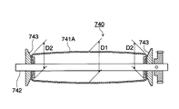
図6は、袋体741の他の実施の形態を示す断面図である。
【0067】
袋体741Aの外周面は、回転軸742の軸方向の中央部の外径D1が、両端部の外径D2より大きい中高の太鼓形状に形成されている(D1>D2)。これにより、定着ベルト73の回動時の片寄りを防止する。
【0068】
(第4の実施の形態)
次に、本発明の定着装置の第4の実施の形態を図2及び図4により説明する。
【0069】
定着ベルト73の内側には、ハロゲンヒータ76Aが定着ベルト73の内周面を照射するように設置してある。定着ベルト73はこのハロゲンヒータ76Aにより所定の温度まで加熱される。
【0070】
定着ベルト73の温度制御は、定着ベルト73の内周面に接触又は近接して設置された温度センサ78により検知された温度に基づいて行われる。温度センサ78には、熱電対、サーミスタ等が用いられる。
【0071】
温度センサ78は、定着ベルト73を支持して回動させる駆動側の支持ローラ74(又は740)と定着ベルト73との接触位置より定着ベルト73の搬送方向上流側の定着ベルト73のテンション側に配置されている。なお、温度センサ78の設置位置は、温度センサ78を定着ベルト73に追従する機構などにより、安定した接触又は近接を保つための手段を施せば、前記位置に限定されるものではない。
【0072】
温度センサ78が定着ベルト73の画像形成領域の内周面に接触又は近接して設置されているから、温度センサ78が画像に影響のある定着ベルト73の外周面に接触して、傷を付けたりすることがない。従って、画像を定着する画像形成領域の温度を正確に検知することが可能となる。
【0073】
また、定着領域において、転写材Pと接触した定着ベルト73は、接触部分だけが熱を奪われるから、その接触部分がハロゲンヒータ76Aによる加熱領域に到達するのにタイミングを合わせて、ハロゲンヒータ76Aを点灯する。
【0074】
本発明の温度センサ78を配置することにより、画像形成領域内の定着ベルト73の温度を検知することが可能となり、画像に影響を与えることなく高精度な温度制御が実現される。
【0075】
【発明の効果】
本発明によるときは、以上説明した構成により、ウォーミングアップ時間の短縮、定着ベルトの片寄りの防止、定着ベルトの温度検知精度向上、高速定着及び高画質の定着が可能で、安全化、静音化と寿命の長い定着装置及び該定着装置を備えた画像形成装置が提供される。
【図面の簡単な説明】
【図1】本発明の定着装置を搭載した画像形成装置であるカラープリンタを示す断面構成図。
【図2】本発明の定着装置の一実施の形態を示す断面図。
【図3】上記の定着装置の平面図。
【図4】本発明の定着装置の第2の実施の形態を示す正面図。
【図5】第2の実施の形態の定着装置の断面図。
【図6】定着ローラの袋体の他の実施の形態を示す断面図。
【符号の説明】
7 定着装置
71,72 加圧ローラ
72A 支持軸
73 定着ベルト
74,75、740,750 支持ローラ
74A,75A ローラ部
74B,75B,742 回転軸
74C,75C,743 フランジ部材
741,741A 袋体
76 加熱手段
76A ハロゲンヒータ(加熱源)
76B 反射板
77 クリーニング手段
78 温度センサ
D1,D2 外径
P 転写材[0001]
BACKGROUND OF THE INVENTION
The present invention relates to a belt-type fixing device of an electrophotographic image forming apparatus.
[0002]
[Prior art]
2. Description of the Related Art Conventionally, a fixing device used in an electrophotographic image forming apparatus has an unfixed toner by a heating roller maintained at a predetermined temperature and a pressure roller having an elastic layer and being in pressure contact with the heating roller. A heat roller fixing system in which a recording material on which an image is formed is nipped and conveyed while being heated is frequently used.
[0003]
However, in this type of apparatus, the heat capacity of the heating roller is increased, the warm-up time is increased, the temperature inside the elastic layer is increased, and the life of the roller is shortened.
[0004]
Further, many color images have a large solid area, and there are many solid images other than black, and uneven gloss is conspicuous. In the case where a hard roller is used as the heating and pressure roller, there is a problem in that the unevenness of the gloss according to the unevenness of the paper or the toner layer occurs, so that the image quality is deteriorated.
[0005]
[Problems to be solved by the invention]
In order to solve the above problems, a fixing method using a rubber roller or a rubber belt has been proposed.
[0006]
Good image quality can be obtained by using a rubber roller, but there are problems such as warming up time and short roller life. This problem becomes more prominent as the speed of copiers and printers increases. It has become to.
[0007]
The fixing device using the fixing belt has the following problems.
[0008]
(1) In a system in which tension is applied using a rubber belt for fixing, the force that the belt tries to offset is large, and the cost of the unit is high and the reliability is not necessarily high for this measure.
[0009]
(2) In a fixing device in which a fixing belt suspended on a plurality of support rollers is heated and fixed by a heating means, heat escapes from the heated heating roller to the contact surface with the support roller, thereby extending the warm-up time. .
[0010]
(3) If protrusions parallel to the rotation shaft are formed on the surface of the support roller in order to reduce the contact area between the support roller and the fixing belt, noise is generated due to intermittent contact between the support roller and the fixing belt.
[0011]
(4) In a fixing device using a fixing belt, it is necessary to detect the temperature of the fixing belt in the image area and control the temperature. However, if a temperature sensor is installed on the outer peripheral surface of the fixing belt, it is generated on the surface of the fixing belt. Since a minute scratch causes an image defect, it is necessary to install a temperature sensor in a non-image area. The non-image area is not deprived of heat by the transfer material, and the temperature is different from that of the image area deprived of heat by the transfer material. Therefore, it has been difficult to control the temperature to an optimum temperature for fixing.
[0012]
(5) When a temperature sensor is installed on the outer peripheral surface of the fixing belt, toner or paper dust attached to the surface of the fixing belt causes a temperature detection failure.
[0013]
(6) If the heating means for heating the fixing belt is installed opposite to the outer peripheral surface of the fixing belt, the heating means is exposed, which is not preferable from the viewpoint of safe operation, and further close to the transfer material carried into the pressure roller. Then, there is a risk of overheating.
[0014]
The object of the present invention is to solve the above-mentioned problems, shorten the warm-up time, improve the temperature detection accuracy of the fixing belt, fast fixing and high-quality fixing, and make the fixing device safe and quiet and have a long life and the fixing An object of the present invention is to propose an image forming apparatus provided with the apparatus.
[0015]
[Means for Solving the Problems]
[0016]
The fixing device of the present invention is a fixing device that fixes a transfer material carrying a toner image by heating and pressurizing. The fixing belt is wound around at least two support rollers and is rotatable, and the fixing belt is heated. A heating unit; and at least two pressure rollers that fix the transfer material carrying the toner image by sandwiching and conveying the fixing belt and the transfer material to be fixed and heating and pressurizing. The support roller inscribed in the fixing belt is surrounded by a hollow cylindrical bag body sealed with a gas layer, and the internal pressure of the bag body is made higher than the atmospheric pressure. (Claim 1 ).
[0018]
The image forming apparatus of the present invention, which is characterized Fixing belt according to any one of the claims 1-5, heating means, pressure roller, by comprising a fixing device comprising a temperature sensor (Claim 6 ).
[0019]
DETAILED DESCRIPTION OF THE INVENTION
Hereinafter, a fixing device of the present invention and an image forming apparatus equipped with the fixing device will be described with reference to the drawings.
[0020]
FIG. 1 is a sectional view showing a color printer which is an image forming apparatus equipped with a fixing device of the present invention.
[0021]
In this color printer, four sets of scorotron chargers (hereinafter referred to as chargers) 2Y, 2M are disposed around a flexible endless belt-like photoreceptor (hereinafter referred to as a photoreceptor) 1 as an image carrier. , 2C, 2K, four sets of image exposure devices (scanning optical devices) 3Y, 3M, 3C, 3K, and four sets of developing
[0022]
The photosensitive member 1 is stretched around the driving roller 11, the
[0023]
The toner of the two-component developer used in the color image forming apparatus is a colorant composed of pigments or dyes such as yellow, magenta, and cyan, and a black pigment such as carbon black, a binder resin, a release agent, a charge control agent, etc. Containing. As the carrier, ferromagnetic particles such as ferrite, magnetite, and iron powder are used. Preferably, the surface of the ferromagnetic particles is coated with a resin such as a fluorine-based resin or a silicone-based resin.
[0024]
At the start of image recording, a driving motor (not shown) rotates and the photosensitive member 1 rotates clockwise through the driving roller 11, and the charging device 2 </ b> Y charges the photosensitive member 1. Application of a potential is started. After the photoconductor 1 is applied with a potential, exposure by an electric signal corresponding to the first color signal, that is, the yellow (Y) image signal is started in the image exposure device 3Y, and the photoconductor 1 is rotated (sub-scanning). As a result, an electrostatic latent image corresponding to the yellow (Y) image of the developed image is formed on the photosensitive layer on the surface. The latent image is reversely developed with the developer adhered and conveyed on the developing
[0025]
Next, the photosensitive member 1 is further applied with a potential on the yellow (Y) toner image by the charging action of the
[0026]
By the same process, a cyan (C) toner image corresponding to the third color signal is further formed by the charger 2C, the
[0027]
In the developing operation by the developing
[0028]
Thus, the color toner image formed on the peripheral surface of the photoreceptor 1 reaches the transfer region after the potential of the adhered toner is made uniform by the
[0029]
The transfer material P onto which the toner image has been transferred is separated from the circumferential surface of the photoreceptor 1 along the curvature of the drive roller 11 and then conveyed to the fixing device 7. The toner image is melted by the fixing device 7 and fixed to the transfer material P. After the fixing process is completed, the transfer material P is transported by a pair of
[0030]
On the other hand, the photoreceptor 1 from which the transfer material P has been separated is rubbed by the cleaning blade 91 of the cleaning device 9 to remove residual toner and be cleaned. When the toner image of the next document image is subsequently formed, the pre-charge
[0031]
(First embodiment)
FIG. 2 is a sectional view showing an embodiment of the fixing device of the present invention, and FIG. 3 is a plan view of the fixing device.
[0032]
In FIG. 2,
[0033]
At least one of the pair of
[0034]
The fixing
[0035]
The silicone rubber layer is, for example, a belt having a thickness of 0.2 mm, a rubber hardness of 3 ° to 60 ° (JISA), and a small heat capacity. Further, the inner circumference of the fixing
[0036]
The fixing
[0037]
The fixing
[0038]
As shown in FIG. 3, the
[0039]
The
[0040]
The
[0041]
The
[0042]
In order to reduce the contact area with the fixing
[0043]
When both the
[0044]
When one of the two support rollers is driven to be driven via the fixing
[0045]
The inclined surface of the
[0046]
The
[0047]
Inside the fixing
[0048]
As the transfer material P holding the toner image is conveyed to the fixing region via the
[0049]
A predetermined load acts on the
[0050]
The strength of this pressure is adjusted to 0.2 to 2 kg / cm, preferably 0.6 to 1.0 kg / cm per unit length in the direction parallel to the axis of the
[0051]
The pressing by the
[0052]
The toner rubber image on the transfer material P is in contact with the silicone rubber belt of the fixing
[0053]
In addition, an elastic layer made of silicone rubber is provided on the outer periphery of the
[0054]
The fixed transfer material P is separated by the fixing
[0055]
The fixed transfer material P is cooled by the outside air when it comes out of the nip portion by the
[0056]
(Second Embodiment)
FIG. 4 is a front view showing a second embodiment of the fixing device of the present invention, and FIG. 5 is a sectional view. In addition, about the code | symbol used in these drawings, the same code | symbol as FIG. 2, FIG. 3 is attached | subjected to the part which has the same function as the said embodiment. Further, differences from the embodiment will be described.
[0057]
The fixing
[0058]
The
[0059]
The
[0060]
That is, the
[0061]
The film thickness of the
[0062]
The
[0063]
The film thickness of the
[0064]
As a result, when the fixing device 7 is warmed up, only the fixing
[0065]
A
[0066]
(Third embodiment)
FIG. 6 is a cross-sectional view showing another embodiment of the
[0067]
The outer peripheral surface of the
[0068]
(Fourth embodiment)
Next, a fourth embodiment of the fixing device of the present invention will be described with reference to FIGS.
[0069]
Inside the fixing
[0070]
The temperature control of the fixing
[0071]
The
[0072]
Since the
[0073]
Further, in the fixing region, since the fixing
[0074]
By disposing the
[0075]
【The invention's effect】
According to the present invention, with the above-described configuration, the warm-up time can be shortened, the fixing belt can be prevented from being displaced, the temperature detection accuracy of the fixing belt can be improved, high-speed fixing, and high-quality fixing can be achieved. A fixing device having a long life and an image forming apparatus including the fixing device are provided.
[Brief description of the drawings]
FIG. 1 is a cross-sectional configuration diagram showing a color printer which is an image forming apparatus equipped with a fixing device of the present invention.
FIG. 2 is a cross-sectional view showing an embodiment of a fixing device of the present invention.
FIG. 3 is a plan view of the fixing device.
FIG. 4 is a front view showing a second embodiment of the fixing device of the present invention.
FIG. 5 is a cross-sectional view of a fixing device according to a second embodiment.
FIG. 6 is a sectional view showing another embodiment of a fixing roller bag.
[Explanation of symbols]
7 Fixing
Claims (6)
少なくとも2本の支持ローラに巻回されて回動可能な定着ベルトと、A fixing belt that is wound around at least two support rollers and is rotatable;
前記定着ベルトを加熱する加熱手段と、Heating means for heating the fixing belt;
前記定着ベルトと定着する前記転写材とを重ねた状態で挟持搬送して加熱加圧することにより前記トナー像を担持する転写材を定着する少なくとも2本の加圧ローラと、を備え、And at least two pressure rollers for fixing the transfer material carrying the toner image by sandwiching and conveying the fixing belt and the transfer material to be fixed in a state of being heated and pressed.
前記定着ベルトに内接する前記支持ローラの回転軸の周囲を、気体層を介して密閉する中空円筒状の袋体となし、該袋体の内部圧力を、大気圧より高くしたことを特徴とする定着装置。The periphery of the rotating shaft of the support roller inscribed in the fixing belt is formed as a hollow cylindrical bag body hermetically sealed with a gas layer, and the internal pressure of the bag body is set higher than atmospheric pressure. Fixing device.
Priority Applications (1)
| Application Number | Priority Date | Filing Date | Title |
|---|---|---|---|
| JP26960999A JP3721884B2 (en) | 1999-09-24 | 1999-09-24 | Fixing apparatus and image forming apparatus |
Applications Claiming Priority (1)
| Application Number | Priority Date | Filing Date | Title |
|---|---|---|---|
| JP26960999A JP3721884B2 (en) | 1999-09-24 | 1999-09-24 | Fixing apparatus and image forming apparatus |
Publications (3)
| Publication Number | Publication Date |
|---|---|
| JP2001092284A JP2001092284A (en) | 2001-04-06 |
| JP2001092284A5 JP2001092284A5 (en) | 2004-12-02 |
| JP3721884B2 true JP3721884B2 (en) | 2005-11-30 |
Family
ID=17474750
Family Applications (1)
| Application Number | Title | Priority Date | Filing Date |
|---|---|---|---|
| JP26960999A Expired - Fee Related JP3721884B2 (en) | 1999-09-24 | 1999-09-24 | Fixing apparatus and image forming apparatus |
Country Status (1)
| Country | Link |
|---|---|
| JP (1) | JP3721884B2 (en) |
Families Citing this family (2)
| Publication number | Priority date | Publication date | Assignee | Title |
|---|---|---|---|---|
| WO2007145472A1 (en) * | 2006-06-14 | 2007-12-21 | Hyung Woo Kim | Electro photographic type image forming apparatus |
| JP6155430B2 (en) * | 2012-10-16 | 2017-07-05 | 株式会社リコー | Heat treatment apparatus and heat treatment method |
-
1999
- 1999-09-24 JP JP26960999A patent/JP3721884B2/en not_active Expired - Fee Related
Also Published As
| Publication number | Publication date |
|---|---|
| JP2001092284A (en) | 2001-04-06 |
Similar Documents
| Publication | Publication Date | Title |
|---|---|---|
| JP4280664B2 (en) | Image heating device | |
| JP6176437B2 (en) | Fixing apparatus and image forming apparatus | |
| WO2010016624A1 (en) | Image heating device | |
| JP2004296188A (en) | Heating device | |
| JP3721884B2 (en) | Fixing apparatus and image forming apparatus | |
| JP4193429B2 (en) | Image forming apparatus | |
| JP2003195669A (en) | Fixing device and image forming apparatus | |
| JP2009288464A (en) | Image forming apparatus | |
| KR100708171B1 (en) | Fixing device and image forming apparatus having the same | |
| JP2014056007A (en) | Fixing device and image forming device | |
| JP6426116B2 (en) | Fixing device and image forming apparatus | |
| KR20060053254A (en) | Fixerand image forming apparatus employing the same | |
| JPH10319753A (en) | Heater, heating device and image forming device | |
| JP4577044B2 (en) | Image forming apparatus | |
| JP2006133326A (en) | Fixing device and image forming apparatus | |
| JP2002268419A (en) | Image forming device | |
| JP3738626B2 (en) | Fixing apparatus and image forming apparatus | |
| JP2001109288A (en) | Fixing device and image forming device | |
| JP2007065217A (en) | Image forming apparatus | |
| JP2004013026A (en) | Fixing device | |
| JP2001117400A (en) | Fixing device and image forming device | |
| JP2005173289A (en) | Fixing device | |
| JP2020076821A (en) | Fixing device and image forming apparatus | |
| JPH0325479A (en) | Fixing device | |
| JP2000056596A (en) | Fixing device |
Legal Events
| Date | Code | Title | Description |
|---|---|---|---|
| A521 | Written amendment |
Free format text: JAPANESE INTERMEDIATE CODE: A523 Effective date: 20031215 |
|
| A621 | Written request for application examination |
Free format text: JAPANESE INTERMEDIATE CODE: A621 Effective date: 20031215 |
|
| A977 | Report on retrieval |
Free format text: JAPANESE INTERMEDIATE CODE: A971007 Effective date: 20050408 |
|
| A131 | Notification of reasons for refusal |
Free format text: JAPANESE INTERMEDIATE CODE: A131 Effective date: 20050426 |
|
| TRDD | Decision of grant or rejection written | ||
| A01 | Written decision to grant a patent or to grant a registration (utility model) |
Free format text: JAPANESE INTERMEDIATE CODE: A01 Effective date: 20050823 |
|
| A61 | First payment of annual fees (during grant procedure) |
Free format text: JAPANESE INTERMEDIATE CODE: A61 Effective date: 20050905 |
|
| R150 | Certificate of patent or registration of utility model |
Free format text: JAPANESE INTERMEDIATE CODE: R150 |
|
| FPAY | Renewal fee payment (event date is renewal date of database) |
Free format text: PAYMENT UNTIL: 20080922 Year of fee payment: 3 |
|
| FPAY | Renewal fee payment (event date is renewal date of database) |
Free format text: PAYMENT UNTIL: 20090922 Year of fee payment: 4 |
|
| FPAY | Renewal fee payment (event date is renewal date of database) |
Free format text: PAYMENT UNTIL: 20090922 Year of fee payment: 4 |
|
| FPAY | Renewal fee payment (event date is renewal date of database) |
Free format text: PAYMENT UNTIL: 20100922 Year of fee payment: 5 |
|
| FPAY | Renewal fee payment (event date is renewal date of database) |
Free format text: PAYMENT UNTIL: 20110922 Year of fee payment: 6 |
|
| FPAY | Renewal fee payment (event date is renewal date of database) |
Free format text: PAYMENT UNTIL: 20120922 Year of fee payment: 7 |
|
| FPAY | Renewal fee payment (event date is renewal date of database) |
Free format text: PAYMENT UNTIL: 20120922 Year of fee payment: 7 |
|
| FPAY | Renewal fee payment (event date is renewal date of database) |
Free format text: PAYMENT UNTIL: 20130922 Year of fee payment: 8 |
|
| S531 | Written request for registration of change of domicile |
Free format text: JAPANESE INTERMEDIATE CODE: R313531 |
|
| S533 | Written request for registration of change of name |
Free format text: JAPANESE INTERMEDIATE CODE: R313533 |
|
| R350 | Written notification of registration of transfer |
Free format text: JAPANESE INTERMEDIATE CODE: R350 |
|
| LAPS | Cancellation because of no payment of annual fees |