JP3720573B2 - Image search apparatus and method - Google Patents
Image search apparatus and method Download PDFInfo
- Publication number
- JP3720573B2 JP3720573B2 JP09013398A JP9013398A JP3720573B2 JP 3720573 B2 JP3720573 B2 JP 3720573B2 JP 09013398 A JP09013398 A JP 09013398A JP 9013398 A JP9013398 A JP 9013398A JP 3720573 B2 JP3720573 B2 JP 3720573B2
- Authority
- JP
- Japan
- Prior art keywords
- label
- image
- image data
- search
- matching
- Prior art date
- Legal status (The legal status is an assumption and is not a legal conclusion. Google has not performed a legal analysis and makes no representation as to the accuracy of the status listed.)
- Expired - Fee Related
Links
Images


Landscapes
- Information Retrieval, Db Structures And Fs Structures Therefor (AREA)
- Processing Or Creating Images (AREA)
Description
【0001】
【発明の属する技術分野】
本発明は、画像を検索する画像検索装置及び方法に関するものである。
【0002】
【従来の技術】
従来より類似画像を検索するための種々の技術が提案されている。類似画像検索を自然画像について行うための、ある程度実用化されている技術では、色情報を画像特徴量として用いているものが多い。そして、その多くが、色情報に関するヒストグラムを取ることにより、RGBの割合や画像中に多く存在する色の組み合わせを用いて検索を行うものである。
【0003】
【発明が解決しようとする課題】
しかしながら、上記の手法では、色の位置情報が失われてしまうためにその検索精度は必ずしも高くなかった。また、例えば特開平8−249349号には、画像を複数のブロックに分け夫々の特徴量(代表色)を用いたパターンマッチングが開示されている。しかしながら、この手法では、マッチングを行う2つの画像について各ブロック間の特徴量の距離を計算しなければならず、膨大な計算量が必要となってしまう。特に特徴量として代表色を用いると、RGB3個のデータを扱わなければならず、更に計算が複雑なものとなる。また、特徴量そのものを用いて比較を行うので、比較の精度が高くなる反面、画像のアングルが変ったり、物体の位置が変ったりするだけで類似画像検索できなくなってしまうといった問題がある。すなわち、画像のアングルが変ったり、物体の位置が変ったり、あるいは撮影条件による画像特徴量のある程度の違い等を吸収するなど、ある程度の曖昧さを有しながらも適切に画像検索を行うという、いわゆるロバストな類似画像検索を行うことはできなかった。
【0004】
従って、従来技術において自然画像を検索する場合には、画像にキーワードを付与しておき、このキーワードによって画像検索を行うことが普通であった。しかし、このキーワード付け作業は人手のかかる作業であり、更に、キーワード付けが行われていない画像に関しては、縮小画を提示してマニュアルにて選択するという作業が生じ、検索操作を煩雑なものとしていた。
【0005】
本発明は上記の問題点に鑑みてなされたものであり、画像の特徴量の配置を考慮した高速な類似画像の検索を可能とする画像検索装置及び方法を提供することを目的とする。
【0006】
また、本発明の他の目的は、画像の特徴量の配置を考慮した類似画像の検索を行うとともに、撮影条件の変動等による違いを吸収した類似画像検索を可能とする画像検索装置及び方法を提供することにある。
【0007】
また、本発明の他の目的は、特徴量群を1つのラベルで表し、画像をラベル列もしくはラベル行列で表現して画像間の類似度を算出することにより類似度の計算量を減少させ、迅速な類似画像検索を可能とすることにある。
【0008】
また、本発明の他の目的は、ラベル列もしくはラベル行列を適切に管理し、ラベルを用いた画像検索処理の処理速度を著しく向上することにある。
【0009】
また、本発明の他の目的は、元画像と比較先画像の類似度をラベル列もしくはラベル行列の比較によって行う際に、DPマッチングやファジー非決定性オートマトン等のラベル位置の前後の曖昧さを許す手法を適用し、より効果的な類似画像検索を可能とすることにある。
【0010】
【課題を解決するための手段】
上記の目的を達成するための本発明の画像検索装置は以下の構成を備える。即ち、
画像データを複数のブロックに分割し、各ブロックについて取得された特徴量に応じてラベルを付与する付与手段と、
前記付与手段で付与されたラベルを所定のブロック順序に基づいて並べることによりラベル列を生成する生成手段と、
前記生成手段で生成されたラベル列を前記画像データに対応付けて記憶する第1記憶手段と、
前記生成されたラベル列に基づいて、前記画像データをラベルをキーとして、ラベル毎に当該ラベルを含む画像データを示す画像IDを登録するとともに、各画像データにおける当該ラベルの含有数を登録するインデックステーブルを記憶する第2記憶手段と、
検索元となる検索元画像データが与えられた場合、該検索元画像データに対応するラベル列を獲得し、前記インデックステーブルに登録されている画像IDとラベルの含有数とに基づき、該獲得されたラベル列に類似する画像データ群を抽出する抽出手段と、
前記抽出手段で抽出された画像データ群のそれぞれについて、前記第1記憶手段に記憶されたラベル列に基づいて前記検索元画像データに対応する画像データの検索を行う検索手段とを備える。
【0011】
また、本発明の他の形態によれば、上記画像検索装置に対応する画像検索方法、及び該画像検索方法を実現するための制御プログラムを格納する記憶媒体が提供される。
【0012】
【発明の実施の形態】
以下、添付の図面を参照して本発明の好適な一実施形態を説明する。
【0013】
[第1の実施形態]
図1は第1の実施形態による画像検索装置の制御構成を示すブロック図である。同図において、101はCPUであり、本実施形態の画像検索装置における各種制御を実行する。102はROMであり、本装置の立ち上げ時に実行されるブートプログラムや各種データを格納する。103はRAMであり、CPU101が処理するための制御プログラムを格納するとともに、CPU101が各種制御を実行する際の作業領域を提供する。104はキーボード、105はマウスであり、ユーザによる各種入力操作環境を提供する。
【0014】
106は外部記憶装置であり、ハードディスクやフロッピー(登録商標)ディスク、CD−ROM等で構成される。107は表示器である。108はネットワークインターフェースであり、ネットワーク上の各機器との通信を可能とする。109はインターフェース、110は画像読み取りのためのスキャナである。また、111は上記の各構成を接続するバスである。なお、後述の各フローチャートに示される処理を実現する制御プログラムは、ROM102に格納されていてもよいし、外部記憶装置106よりRAM103にロードされてもよい。
【0015】
なお、上記の構成においてスキャナ110や外部記憶装置106はネットワーク上に配置されたもので代用してもよい。
【0016】
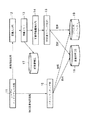
図2は第1の実施形態の画像検索装置の機能構成を示すブロック図である。同図において、11はユーザインターフェース部であり、表示器107、キーボード104及びマウス105を用いて、ユーザからの各種の操作入力を検出する。12は画像入力部であり、スキャナ110による画像の読み取りを行う。13は画像メモリであり、画像入力部12によって得られたイメージデータをRAM103の所定の領域に格納する。14は画像特徴量抽出部であり、画像メモリ13に格納した画像について、後述の手順で特徴量を抽出する。15は特徴量ラベル列化部であり、画像特徴量抽出部14によって得られた特徴量に基づいてラベル列を生成する。16はパターンマッチング部であり、指定された画像のラベル列と、画像蓄積部17に蓄積されている画像のラベル列に基づいて、両者の類似度を算出し、類似画像を検索する。
【0017】
17は画像蓄積部であり、画像入力部12等によって得られた画像データを蓄積する。図3は画像蓄積部17における画像データの格納状態を説明する図である。各画像データ112には画像ID111が付与され、画像蓄積部17にはこれらが対になって保持される。18は画像管理データベース(以下、画像管理DB)であり、図8で示されるデータ形態で画像蓄積部17に格納された画像データを管理する。また、19はラベル列インデックスであり、図10に示されるラベル成分インデックスファイルを格納する。なお、ラベル成分インデックスの利用については、図9のフローチャートにより後述する。
【0018】
以上のような構成を備えた本実施形態の画像検索装置の動作例を以下に説明する。なお、以下の例では色に着目した画像特徴量として、赤(R)、緑(G)、青(B)の三色を採用し、3次元の色空間での処理を用いて説明する。
【0019】
[画像の登録処理]
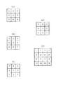
先ず画像登録の際に行う処理を説明する。図4は第1の実施形態による画像登録処理の手順を表すフローチャートである。まず、ステップS11において、ユーザーインターフェース部11を介したユーザの指示により、画像入力部12を用いた画像を読み込み、画像メモリ13に保持する。次に、ステップS12において、この画像を複数のブロックに分割する。本実施形態では、画像を縦横の複数ブロックに分割する。図5は本実施形態による画像のブロック分割例を示す図である。同図に示されるように、本実施形態では、説明のため3×3の計9個のブロックに画像を分割するものとする。次にステップS13において、分割された各ブロックの特徴量を算出し、得られた特徴量を次の手順でラベル化する。
【0020】
なお、本実施形態で用いる3×3への分割はあくまで説明のためのものである。実際には、自然画であれば10×10以上の分割数とするのが好ましい。また、白の無地背景に商品が写っているような場合であれば、13×13以上の分割数とするのが好ましい。
【0021】
図6は本実施形態による多次元特徴量空間を説明する図である。図6に示すように、多次元特徴量空間(RGBカラー空間)を複数のブロック(色ブロック)、即ちセル(色セル)に分割し、夫々のセル(色セル)に対して通し番号でユニークなラベルを付与する。ここで、多次元特徴量空間(RGBカラー空間)を複数のブロックに分けたのは微妙な特徴量(色)の違いを吸収するためである。
【0022】
なお、多次元特徴量空間に関しては、画像特徴量をそのまま用いるものではなく各パラメータを平均と分散を実験によって求め規格化(正規化)した後、例えば、主成分分析等の直交変換を行い、意味のある次元にしたものを用いることが考えられる。なお、「意味のある次元」とは、主成分分析において、寄与率が大きな主成分軸で構成される次元である。
【0023】
ステップS13では、ステップS12で得られた各分割ブロックに対して、定められた画像特徴量計算処理を行い、上記多次元特徴量空間上のどのセルに属するかを求め、対応するラベルを求める。この処理を全てのブロックに対して行う。すなわち、分割画像ブロックに対して、全ての画素がどの色セルに属するかの計算処理を行い、もっとも頻度の多い色セルのラベルをその分割画像ブロックのパラメータラベル(カラーラベル)として決定し、この処理を全てのブロックに対して行う。
【0024】
以上のようにして各ブロックに対してパラメータラベルが付与されると、ステップS14において、各ブロックに付与されたパラメータラベルを所定のブロック順序で並べることにより、パラメータラベル列(以下、ラベル列とする)が生成される。図7はラベル列を生成する際のブロック順序例を説明する図である。同図の分割画像ブロックの升にある数字に従って上記のパラメータラベルを並べ、ラベル列を作る。
【0025】
ここで、図7の(a)では、分割ブロックを右上から左下方向への斜め方向へスキャンしている。これは、比較する画像のアングルの微妙な違い、ずれの影響を少なくするために類似検索対象物体に沿ってなるべく多く連続したラベル列を高い期待値で得るためである。この結果、後で述べるパターンマッチング部16の作用とあいまって、上下左右のどちらのずれに対しても影響の少ないラベル列同士の比較が可能となる。
【0026】
なお、本実施形態に適用可能なスキャンの方法としては、
・水平方向(左から右へのスキャンを上から下へ行う、左から右へのスキャンを下から上へ行う等、4通りのスキャン方法が考えられる)、
・垂直方向(上から下へのスキャンを左から右へ行う等、4通りのスキャン方法が考えられる)、
・斜め方向(四隅の各始点について2方向の斜めスキャンがあり、図7の(a)〜(c)を含む8通りのスキャン方法がある)、
・ジグザグスキャン(JPEG等において採用されているスキャン方法であり、四隅の各始点について2通りのジグザグスキャンがあり、合計8通りのスキャンがある)、
等があげられる。本実施形態では以下の観点から採用すべきスキャン方法を決定する。すなわち、
(1)本実施形態ではラベル列同士の時系列的な比較であり、この順序に逆転が生じることは好ましくない。よって、すべての画像を所定のスキャン方法でスキャンしてラベル列化を行う必要がある。
(2)位置の近いブロックはラベル列中においても近くに位置することが望ましい。
(3)検索したい物体に引っ掛かるブロックのラベルが出来る限り早く現れ、且つ長く続くことがマッチングを行いやすくする。
(4)物体が動いたり、アングルが変わったりしても、ラベルの並びが極端に変わらないようにする。
という条件を満足するスキャン方法を採用する。特に、着目物体の多くが画像中央であることを仮定すると、着目物体を含むブロックが出来るだけスキャンの早いうちに現れ、長くその着目物体をスキャンする期待値が高い方法として、本実施形態では斜め方向のスキャンを採用している。なお、本実施形態では、図7の(a)のような右上から左下方向への斜めスキャンを採用するが、当然、図7の(b)のような例や図7の(c)の様なスキャン方法を採用してもよい。
【0027】
続いてステップS15において、以上のようにして得たラベル列や画像データを画像蓄積部17、画像管理DB18、ラベル列インデックス19に格納する。すなわち、ステップS11で読み込んだ画像データに対して画像IDを取得し、これらをペアにして画像蓄積部17に格納する。そして、当該画像IDに対応付けて図8に示す画像管理DBレコードを生成し、これを画像管理DB18に登録する。
【0028】
以上が画像登録時に行われる処理である。
【0029】
[類似画像検索処理]
次に図9のフローチャートに従って類似画像検索の処理を説明する。図9は第1の実施形態による類似画像検索の処理手順を説明するフローチャートである。なお、第1の実施形態では、予め初期化時において、画像管理DBのラベル系列から、既に登録されている画像のラベル列群を得て、各ラベル成分をキーとするラベル成分インデックスファイル(図10)を生成し、ラベル列インデックス19に格納しておく。なお、ここでいう初期化時とは、システムの立ち上げ時或いはアプリケーションの起動時のいずれでも良い。また、新規の画像登録があり、これを画像DBに登録した場合にも、このラベル成分インデックスの生成を行う。図10は、ラベル成分インデックスのデータ構成例を示す図である。図10に示すように、ラベル成分インデックスには、各ラベル成分毎に、そのラベルを内部に持つラベル列へのアドレス群(列ID群)を有する。なお、このラベル成分インデックスファイルは画像の登録及び削除、変更を反映する必要が生じるまで、作成し直す必要はない。もちろん、毎回画像データの登録時にラベル成分インデックスを追記してゆく方法も存在する。この場合は、図4のステップS15の後で、新たに登録された画像について上述した処理を行う。
【0030】
図10に示すラベル成分インデックスには、ラベル成分をキーとして、そのラベル成分を含む画像IDとそれに含まれる当該ラベルの個数が格納されている。このようなインデックスを用いれば、検索元画像が有するラベル成分を含む画像データの画像IDを直接的に抽出できる。なお、各キー毎に格納されている画像IDを、ラベルの個数にしたがって昇順或いは降順にソートして登録しておけば、より処理速度を向上させることができる。
【0031】
まず、ステップS21において、ユーザーインターフェース部11から類似検索元画像が指定されると、ステップS22において、指定された類似検索元画像の画像IDが取得され、更に画像管理DB18から当該元画像のラベル列(本例ではカラーラベル列)が取得される。
【0032】
次にステップS23において、ラベル成分インデックスファイルを参照し、類似検索元画像のラベル列とある程度以上同一のラベルを含むラベル列群(ラベル系列インデックス中のラベル列)を取得する。これは登録した画像の全てのラベル列との比較を行うと処理が遅くなるので、予め似ているものに絞った後に、類似検索元画像のラベル列と一対一で比較するようにし、処理速度を改善するためである。なお、類似したラベル列とは、類似検索元画像のラベル列と所定数以上の同一もしくは類似のラベルを含むラベル列群をいう。ここで、類似のラベルとは後述の図11のラベル間ペナルティの小さいラベル同士をいう。もちろん、処理が遅くなっても良ければ、登録した画像の全てのラベル列との比較を行い、精度の高い検索を行ってもよい(この場合、ステップS23は省略される)。
【0033】
なお、上述のラベル成分インデックスファイルを用いた画像の絞り込み方としては、次のような方法が考えられる。例えば、本例では9個のラベルからなるラベル列が用いられるが、このラベル列の中央部の3つのラベル(4番目から6番目のラベル)を含む画像を抽出する。一般に、画像の中央部に当該画像の特徴的な情報が存在するからである。
【0034】
次に、ステップS24において、ステップS23で取得した各ラベル列と類似検索元画像のラベル列とを比較し、その類似度を算出する。そして、類似検索元画像のラベル列に最も近いラベル列から順にその類似度とともに検索結果として出力する。
【0035】
ここで、ラベル列同士の類似比較(類似度の算出)を行う方法について述べる。
【0036】
図11はラベル列を比較し類似度を求める際に用いるラベル間のペナルティマトリックスの一例を示す図である。マトリクス中の値が小さい程類似していることになる。例えば、ラベル2とラベル6のペナルティは「7」である。また、同じラベル同士のペナルティは当然のことながら「0」となっている。本マトリクスの使用目的はラベルの類似に応じた距離判定を行うことにある。すなわち、本実施形態では、特徴量空間としてRGBカラー空間を用いているので、色の類似に応じた距離判定が行えることになる。
【0037】
例えば、検索元画像と検索対象画像のラベル列中のそれぞれ対応する位置のラベルの値から図11のペナルティマトリクスを参照して距離を求め、ラベル列中の全ラベルについての距離の和を求めることで、両ラベル列間の距離を得る。例えば、図12に示す例では、検索元画像のラベル列が「112313441」であり、検索対象画像のラベル列が「113224452」であるので、図11のペナルティマトリクスを用いてDPマッチングを行うことにより、図13に示されるように距離(最終解)が求まる。なお、この例では、傾斜制限として次の条件を用いている。すなわち、図14において、格子点(i-1,j),(i-1,j-1),(i,j-1)上のコストをそれぞれg(i-1,j), g(i-1,j-1), g(i,j-1)とし、格子点(i,j)上のペナルティをd(i,j)とした場合に、格子点(i,j)上のコストg(i,j)を以下の漸化式によって求めている。
【0038】
【数1】

以上のように、ラベル間のパターンマッチングの際に隣接するセル同士ではペナルティ(距離)を小さくし、遠いものには大きなペナルティを与えるために図11に示すようなラベル間でのペナルティマトリックスを導入する。ステップS24ではこのペナルティマトリックスを考慮し、ラベル列同士を比較するが、その際に、オートマトン等のラベルシーケンスを曖昧に比較できるマッチングを行うようにしてもよい。このような曖昧化の手法を用いることにより、余分なラベルの付加、ラベルの欠落や同じラベルの繰り返しに対しては低いペナルティが与えられとともに、ラベル間のペナルティには図12のカラーラベル間のペナルティマトリックスを用いてラベル列同士の距離計算を行うことで、曖昧なパターンマッチングが行えるようになる。なお、オートマトンとしては、「特開平8−241335のファジー非決定性有限オートマトンを使用した曖昧な文字列検索方法およびシステム」に記載されている「ファジー非決定性有限オートマトン」を適用することができる。このオートマトンでは、各シンボル間の距離(ペナルティー)が多値でして出来、なお、比較するラベル位置を前後曖昧に移動することが出来、トータルの距離が最小(類似度が最大)となるようなラベル列の比較を実現するための手法として、上述のオートマトンの他に、音声認識等において用いられているDPマッチングがあり、この手法も本実施形態に好適に適用できるものである。
【0040】
更に、上述の曖昧なパターンマッチングに加えて、図7の(a)〜(c)のブロック順序の規則を併用することにより、比較する画像のアングルの微妙な違いやずれの影響を少なく、上下左右のどちらのずれに対しても影響の少ないカラーラベル列同士の比較を行うことが可能となる。すなわち、DPマッチングやファジー非決定性オートマトンは、ラベル列の前後の曖昧さを許容するマッチングであり、画像の位置ずれの影響を吸収する性質を有する。また、アングルの違い等により物体の位置が変わり、ブロックによって切りとられる物体の位置が変わることにより、ブロックの色合いも微妙に異なることが予想されるが、この違いは上述のペナルティーマトリクスにより吸収されることになる。このように、DPマッチング或いはファジーオートマトンによる曖昧さを許容するマッチングと、ペナルティーマトリクスによる特徴量の曖昧さの許容との相乗効果によって、上下左右のずれに対して影響の少ないマッチングを可能としている。更に、図7(a)〜(c)のような斜めスキャンにより、物体の位置の変化によるラベル位置の変化が低減されるので、より効果的にマッチング時の物体のずれの影響を低減できる。
【0041】
次に、ステップS25において、画像管理DB18を参照して、画像ID群の各画像IDについてフルパスのファイル名を取得し、これをユーザに提示する。
【0042】
以上のような処理により、画像のアングルが変ったり、物体の位置が変ったり、あるいは撮影条件が変わったりすることによって生じる、色のある程度の違い等を吸収するなど、ロバストな類似画像検索を高速に行うことが可能となる。
【0043】
なお、ブロック化できない1つの画像に対して1つのパラメータを加味した類似検索の場合には、本発明で得られる類似度(ペナルティの総和を用いて作る)を1つの新たなる特徴量として、統計的な距離尺度に基づく検索を行うことも可能である。また、上記実施形態では、類似度が所定値を越える類似画像を検索結果として得るが、類似度の高い画像から順に前もって指定された個数の画像を検索結果として出力するようにしてもよいことはいうまでもない。
【0044】
以上説明したように、第1の実施形態によれば、特徴量群(特徴量空間を分割して得られる特徴量のグループ)を1つのシンボルで表現し(すなわちラベル化し)、ラベル同士の類似度に基づく距離をペナルティーマトリクスによって与える。このため、2つの画像のブロック間の距離の計算量を大幅に減少させることができるとともに、類似した特徴量が同じラベルで表されることになるので、類似画像の検索を良好に行うことができる。
【0045】
また、(1)ペナルティマトリクスによるラベル同士の距離概念を導入し、(2)DPマッチングやファジー非決定性オートマトン等の、比較するラベル位置を前後曖昧に移動させることが出来、トータルの距離が最小(類似度が最大)となるようなラベル列の比較を実現する手法を導入する、ことにより、画像のアングルが多少変わっても検索することが可能となり、雰囲気の似ている画像を検索できるようになる。
【0046】
更に上記実施形態によれば、インデックスデータベース(ラベル成分インデックス(図10))を用いたことにより、画像検索が更に高速化する。
【0047】
[第2の実施形態]
上記第1の実施形態では、特徴量を表すラベルを1次元に並べて、すなわちラベル列として類似画像検索を行った。第2の実施形態では、特徴量を表すラベルの2次元配置を考慮して、すなわちラベル行列を用いて類似画像検索を行う。なお、第2の実施形態による画像検索装置の制御構成は、第1の実施形態(図1)と同様であるのでここでは説明を省略する。
【0048】
図15は本実施形態の画像検索装置の機能構成を示すブロック図である。同図において、ユーザインターフェース部11、画像入力部12、画像メモリ13、画像特徴量抽出部14、画像蓄積部17は第1の実施形態(図2)と同様の構成である。
【0049】
15aは特徴量ラベル行列化部であり、画像特徴量抽出部14によって得られた特徴量に基づいてラベル行列を生成する。16aはパターンマッチング部であり、指定された画像のラベル行列と、画像蓄積部17に蓄積されている画像のラベル行列に対し、後述の2次元DPマッチングを用いて類似度を算出する。18aは画像管理データベース(以下、画像管理DB)であり、図16で示すデータ形態で画像蓄積部17に格納された画像データを管理する。また、19aはラベル行列インデックスであり、図10で示したラベル成分インデックスファイルを格納する。
【0050】
以上のような構成を備えた第2の実施形態の画像検索装置の動作例を以下に説明する。なお、以下の例では色に着目した画像特徴量として、赤(R)、緑(G)、青(B)の三色を採用し、3次元の色空間での処理を用いて説明する。
【0051】
[画像の登録処理]
図17は第2の実施形態による画像登録処理の手順を示すフローチャートである。図17において、ステップS11〜S13は第1の実施形態(図4)で説明した処理と同様である。
【0052】
ステップS11〜S13の処理により、各ブロックに対してパラメータラベルが付与されると、ステップS14aにおいて、各ブロックに付与されたパラメータラベルを所定のブロック順序で並べることにより、パラメータラベル行列(以下、ラベル行列とする)が生成される。図18はラベル行列を生成する際のブロック順序例を説明する図である。同図の分割画像ブロックの升にある数字に従って上記のパラメータラベルを並べ、ラベル行列を作る。なお、画像管理データベース18aやラベル行列インデックス19aにラベル行列を格納するに際しては、上述のように2次元的なラベル行列を所定の順序で1次元に並べたものを格納するが、本実施形態ではこのような1次元の形態のものもラベル行列と称することにする。
【0053】
ここで、図18の(a)では、分割ブロックを左から右へ水平方向へスキャンし、この水平方向のスキャンを上から下へ行う順序となっている。なお、本実施形態に適用可能なスキャンの方法としては、
・水平方向(図18の(a)に示したように、左から右へのスキャンを上から下へ行うという順序の他に、図18の(b)〜(d)に示すように、左から右へのスキャンを下から上へ行う等、4通りのスキャン方法がある)、
・垂直方向(上から下へのスキャンを左から右へ行う等、4通りのスキャン方法が考えられる)、
・図18(e)に示すように、偶数ラインと奇数ラインでスキャンを分ける。
【0054】
なお、第2の実施形態では、図18の(a)に示すスキャン方法を採用するが、上述した他のスキャン方法も適用可能である。
【0055】
続いてステップS15aにおいて、以上のようにして得たラベル行列や画像データを画像蓄積部17、画像管理DB18a、ラベル行列インデックス19aに格納する。すなわち、ステップS11で読み込んだ画像データに対して画像IDを取得し、これらをペアにして画像蓄積部17に格納する。そして、当該画像IDに対応付けて図16に示す画像管理DBレコードを生成し、これを画像管理DB18aに登録する。
【0056】
以上が画像登録時に行われる処理である。
【0057】
[類似画像検索処理]
次に図19のフローチャートに従って類似画像検索の処理を説明する。図19は第2の実施形態による類似画像検索の処理手順を説明するフローチャートである。なお、本実施形態では、予め初期化時において、画像管理DBのラベル系列から、既に登録されている画像のラベル行列群を得て、各ラベル成分をキーとするラベル成分インデックスファイルを生成し、ラベル行列インデックス19aに格納しておく。なお、ここでいう初期化時とは、システムの立ち上げ時或いはアプリケーションの起動時のいずれでも良い。また、新規の画像登録があり、これを画像DBに登録した場合にも、このラベル成分インデックスの生成を行う。
【0058】
本実施形態においても、第1の実施形態で説明したラベル成分インデックス(図10)を用いる。すなわち、ラベル成分インデックスには、各ラベル成分毎に、そのラベルを内部に持つラベル行列へのアドレス群(列ID群)が登録される。なお、このラベル成分インデックスファイルは画像の登録及び削除、変更を反映する必要が生じるまで、作成し直す必要はない。もちろん、第1の実施形態で述べたように、毎回登録時にラベル成分インデックスを追記してゆく方法も存在する。
【0059】
まず、ステップS21において、ユーザーインターフェース部11から類似検索元画像が指定されると、ステップS22aにおいて、指定された類似検索元画像の画像IDが取得され、更に画像管理DB18から当該元画像のラベル行列(本例ではカラーラベル行列)が取得される。
【0060】
次にステップS23aにおいて、ラベル成分インデックスファイルを参照し、類似検索元画像のラベル行列とある程度以上同一のラベルを含むラベル行列群(ラベル系列インデックス中のラベル行列)を取得する。これは登録した画像の全てのラベル列との比較を行うと処理が遅くなるので、予め似ているものに絞った後に、類似検索元画像のラベル行列と一対一で比較するようにし、処理速度を改善するためである。なお、類似したラベル行列とは、類似検索元画像のラベル行列と所定数以上の同一もしくは類似のラベルを含むラベル行列群をいう。ここで、類似のラベルとは図11で説明したラベル間ペナルティの小さいラベル同士をいう。もちろん、処理が遅くなっても良ければ、登録した画像の全てのラベル行列との比較を行い、精度の高い検索を行ってもよい(この場合、ステップS23aは省略される)。
【0061】
次に、ステップS24aにおいて、ステップS23aで取得した各ラベル行列と類似検索元画像のラベル行列とを比較し、その類似度を算出する。そして、類似検索元画像のラベル行列に最も近いラベル行列から順にその類似度とともに検索結果として出力する。
【0062】
ここで、ラベル行列同士の類似比較(類似度の算出)を行う方法について述べる。なお、以下では、ステップS23aで取得したラベル行列を類似比較先画像と称する。
【0063】
また、第2の実施形態においてもラベル行列を比較して類似度を求める際には、第1の実施形態と同様にラベル間のペナルティマトリックス(図11)を用いる。
【0064】
ラベル間のパターンマッチングの際に隣接するセル同士ではペナルティ(距離)を小さくし、遠いものには大きなペナルティを与えるために図12に示すようなラベル間でのペナルティマトリックスを導入する。ステップS24aではこのペナルティマトリックスを考慮し、ラベル行列同士を比較するが、第2の実施形態では、その際に以下に説明する2次元的なDPマッチング(以下、2次元DPマッチングという)を使用する。
【0065】
図20は本実施形態による類似度算出処理を説明する図である。上述のステップS22aにおいて取得された類似検索元画像のラベル行列は、そのスキャン方法に従って図20の(b)のように並べることができる。また、ステップS23aにおいて抽出されたラベル行列群のうちの一つを類似検索元画像とすると、そのラベル行列は図20(a)のように並べることができる。
【0066】
まず、類似比較先画像の第1行目のラベル列「abc」と、類似検索元画像の第1〜第3行目のラベル列(「123」、「456」、「789」)のそれぞれとの距離をDPマッチングによって求め、その距離が最少となるラベル列の類似検索元画像における行番号を類似ライン行列(図20の(c))の該当する位置に記憶する。また、得られた最小距離が所定の閾値よりも大きい場合には、どの行とも類似していないと判断し、類似ライン行列の該当する位置に「!」を記憶する。DPマッチングの性質により、たとえば画像のアングルが水平方向へ多少変わっていたとしても、上記処理により類似する行(ライン)を検出可能である。以上の処理を、類似比較先画像の全ての行(「def」「ghi」)について行うことで、図20の(c)のような列方向の類似ライン行列が得られる。
【0067】
図20の(c)では、「abc」に類似した行が類似検索元画像に存在せず、「def」に類似した行が類似検索元画像の第1行目、「ghi」に類似した行が類似検索元画像の第2行目であったことを示している。以上のようにして得られた類似ライン行列と標準ライン行列(類似検索元画像の行の並びであり、本例では「123」となる)との類似度をDPマッチングを用いて算出し、これを当該類似検索元画像と当該類似比較先画像との類似度として出力する。なお、DPマッチングでは、周知のように、比較するラベルシーケンスが最も類似距離が小さくなるように、比較するラベルシーケンスを伸縮(比較する相手を次に進めないで我慢する)させて比較するという処理を行う。また、何処まで伸縮(我慢)できるかを制約条件(整合窓の幅)で与えることも可能である。
【0068】
図21は第2の実施形態による、2次元DPマッチングを採用した類似度算出の手順を説明するフローチャートである。上記図20を参照して説明した処理を、図21のフローチャートを参照して更に説明する。
【0069】
まず、ステップS101において、類似比較先画像の行番号を表す変数iと、類似検索元画像の行番号を表す変数jを1に初期化し、ともに第1行目を示すように設定する。次に、ステップS102において、類似比較先画像の第i行目のラベル列を取得する。例えば図20の場合、i=1であれば「abc」が取得される。そして、ステップS103において、類似検索元画像の第j行目のラベル列を取得する。例えば、図20において、j=1であれば、「123」が取得される。
【0070】
次にステップS104では、上記ステップS102、S103で得られた2つのラベル列間の距離を、図12で説明した色セルペナルティーマトリクスを用いて、DPマッチングによって求める。そして、ステップS105において、ステップS104で得た距離が、第i行目に関してそれまでに得られた距離の最小値であれば、当該行番号(j)をライン行列要素LINE[i]に記憶する。
【0071】
以上のステップS103からステップS105の処理を、類似検索元画像の全ての行について行う(ステップS106、S107)。以上のようにして、類似比較先画像の第i行目のラベル列に対して、類似検索元画像に含まれる行のうち最も距離の近い行の番号がLINE[i]に格納されることになる。
【0072】
そして、ステップS108において、上記処理でられたLINE[i]と所定の閾値(Thresh)とを比較する。そして、LINE[i]がThresh以上であればステップS109へ進み、いずれの行とも類似していないことを表す「!」をLINE[i]に格納する。
【0073】
以上説明したステップS102からS108の処理を類似比較先画像の全ての行について実行する(ステップS110、S111)ことにより、LINE[1]〜LINE[imax]が得られるので、これを類似ライン行列LINE[]として出力する。
【0074】
次に、ステップS113において、標準ライン行列「12…imax」と類似ライン行列LINE[]とのDPマッチングを行い、両者の距離を算出する。なお、ここで、標準ライン行列とは、1から始まり、列方向に1ずつ増加する行列である。
【0075】
ここで、標準ライン行列と類似ライン行列間のDPマッチングにおいて用いられるペナルティーについて説明する。列方向の類似ライン行列と標準ライン行列とのDPマッチングのペナルティーの設定としては2つの方法が考えられる。すなわち、動的なペナルティーと固定的なペナルティーの2つである。
【0076】
動的なペナルティーとは、動的にライン番号間のペナルティーを設定するものであり、画像によってライン番号間のペナルティーは変化する。本実施形態では、類似検索元画像の自分自身の横(行)方向のラベル行列の距離を求め、これに基づいて各行間のペナルティーを求める。
【0077】
図22は第2の実施形態による動的なペナルティー値の設定手順を示すフローチャートである。ステップS121において、変数iを1に、変数jを2にそれぞれセットする。次に、ステップS122において、類似検索元画像の第i行目のラベル列を取得し、ステップS123において、類似検索もと画像の第j行目のラベル列を取得する。そして、ステップS124において、類似検索元画像の第i行目のラベル列と第j行目のラベル列とについて、色ペナルティーマトリクスを用いてDPマッチングを行い、距離を獲得する。ステップS125では、ステップS124で得たDPマッチングの距離を、類似検索元画像のi行目のラベル列とj行目のラベル列間のペナルティーとしてLINE[i][j]に記憶すると共に、、類似検索元画像のj行目のラベル列とi行目のラベル列間のペナルティーとしてLINE[j][i]に記憶する。
【0078】
ステップS126によって、変数jの値がjmaxとなるまで、ステップS123〜S125の処理が繰返される。この結果、第i行目のラベル列について、i+1〜jmax行目の各ラベル列との間のペナルティー値が決定される。そして、ステップS128、S129、S130により、ステップS123〜S126の処理を変数iの値がimax−1となるまで繰返される。この結果、LINE[i]「j]には、i=jの対角成分を除く全てに、上記処理で決定されたペナルティー値が記憶されることになる。
【0079】
次にステップS131では、上記処理で決定されていないLINE[i][j]の対角成分のペナルティーを決定する。この部分はi=jであり、同一のラベル列であるから、その距離は0であり、従ってペナルティー0が記憶される。また、ステップS132では、「!」に関してペナルティーを決定する。すなわち、「!」に対するペナルティーは、LINE[i][j]の全てのペナルティー値の中で、最大のペナルティー値よりもある程度大きな値を設定する。ただし、このペナルティー値を極端に大きくすると、曖昧にヒットする性質が損なわれてしまう。
【0080】
以上のようにして類似検索元画像に関して計算されたラベル列間のペナルティーを用いて、上記ステップS113におけるDPマッチングを行い、類似度検索元画像と類似比較先画像の類似度を獲得する。
【0081】
一方、固定的なペナルティーでは、DPマッチングのペナルティーとして、ラベルが一致すればペナルティー「0」を、一致しない場合、もしくは「!」との比較であった場合にはある程度の大きさのペナルティーを与える。この場合は類似検索元画像によらず、常に同じペナルティーとなる。このような固定的なペナルティーを用いてステップS113の処理を実行し、類似度検索元画像と類似比較先画像の類似度を決定する。
【0082】
以上説明したマッチング処理は次のような特徴を有する。もし、図20の(a)と(b)が極めて類似していれば、類似ライン行列は「123」となり、その距離は0となる。また、類似ライン行列が「!12」や「212」であれば、類似検索元画像に対して類似比較先画像は下方向へずれたものである可能性があるし、類似ライン行列が「23!」や「233」であれば類似検索元画像に対して類似比較先画像が上方向へずれたものである可能性がある。また、類似ライン行列が「13!」や「!13」であれば、類似検索元画像に対して類似比較先画像が縮小したものである可能性がある。同様に、類似比較先画像が類似検索元画像を拡大したようなものである場合も検出可能である。
【0083】
上述のステップS113で説明したように、類似ライン行列と標準ライン行列との間でDPマッチングを行うことにより、垂直方向へのずれが効果的に吸収される。このため、上述したような、上方向や下方向へのずれ、拡大、縮小等に起因する類似検索元画像と類似比較先画像との相違が効果的に吸収され、良好な類似検索を行うことが可能となる。
【0084】
すなわち、本実施形態の2次元DPマッチングは、ラベル行列の各ラベル列における前後の曖昧さを許容するマッチングであり、画像の位置ずれの影響を吸収する性質を有する。また、アングルの違い等により物体の位置が変わり、ブロックによって切りとられる物体の位置が変わることにより、ブロックの色合いも微妙に異なることが予想されるが、この違いは上述のペナルティーマトリクスにより吸収されることになる。このように、本実施形態の2次元DPマッチングによる曖昧さを許容するマッチングと、ペナルティーマトリクスによる特徴量の曖昧さの許容との相乗効果によって、上下左右拡大、縮小のずれに対しても影響の少ないマッチングを可能としている。
【0085】
ただし、動的なペナルティーと固定的なペナルティーとでは、動的なペナルティーを用いる方が好ましい。例えば、一面麦畑の類似元検索画像があったとした場合、どのラインも似たようなラベル列となることが考えられる。一方、類似比較先画像にも一面麦畑の画像があったとした場合に、この画像の類似ライン行列には全て最初のライン番号1が入り、「111」となってしまう可能性がある。この場合、類似検索元画像のどのラインも似たような画像となっており、ライン番号間のペナルティーが極めて小さくなければ低い距離でのヒットはしない。しかしながら、動的なペナルティーを用いた場合は、ライン番号間のペナルティーが低くなり、類似度の高い結果を得ることができる。
【0086】
一方、固定的なペナルティーを用いると、「123」と「111」ではペナルティー値が大きくなり、類似度が低くなってしまう。
【0087】
ステップS24aでは、以上説明した類似度の算出処理をステップS23aで取得した全ラベル行列について行い、得られた類似度を高い順にソートして、ステップS25aへ進む。ステップS25aにおいて、画像管理DB18aを参照して、画像ID群の各画像IDについてフルパスのファイル名を取得し、これをユーザに提示する。
【0088】
以上のようにして、DPマッチングを水平・鉛直方向、すなわち2次元に行うことにより、水平や鉛直方向、更に斜め方向に画像アングルが変わったり、物体が移動していても検索を行うことが可能である。また、DPマッチングの時系列伸縮特性により、ズームアップ撮影画像やマクロ撮影画像をも検索することが可能となる。
【0089】
なお、上記実施形態では、水平方向のブロック並びに対応するラベル列を用いて類似ライン行列を得たが、垂直方向のブロック並びに対応するラベル列を用いて類似ライン行列を得るようにすることも、上記と同様の手法で実現可能である。
【0090】
以上説明したように、第2の実施形態によれば、特徴量群(特徴量空間を分割して得られる特徴量のグループ)を1つのシンボルで表現し(すなわちラベル化し)、ラベル同士の類似度に基づく距離を上述の2次元DPマッチングとペナルティーマトリクスによって与える。このため、2つの画像のブロック間の距離の計算量を大幅に減少させることができるとともに、類似した特徴量が同じラベルで表されることになるので、類似画像の検索を良好に行うことができる。
【0091】
また、(1)ペナルティマトリクスによるラベル同士の距離概念を導入し、(2)比較するラベル位置を前後曖昧に移動させることが出来、トータルの距離が最小(類似度が最大)となるようなラベル行列の比較を実現する上記2次元DPマッチングを導入したことにより、画像のアングルが多少変わっても検索することが可能となり、雰囲気の似ている画像を検索できるようになる。
【0092】
更に上記実施形態によれば、インデックスデータベース(ラベル成分インデックス)を用いたことにより、画像検索が更に高速化する。
【0093】
すなわち、上記実施形態によれば、画像の特徴量の配置を考慮した類似画像の高速な検索が行われるとともに、撮影条件の変動等による違いを吸収した類似画像の検索が可能となり、従来難しかった画像のアングルが変ったり、物体の位置が変ったり、あるいは他の撮影条件が変動したりすることによる画像の特徴量のある程度の違いを吸収するなど、ロバストな類似画像検索を行うことが可能となる。
【0094】
なお、上記各実施形態においては、自然画像検索を行う例を説明したが、本発明はCGやCAD等の人工的な画像の検索にも適応可能な技術であることは当業者には明らかである。
【0095】
また、上記各実施形態では画像特徴量として色情報を選んだが、本発明はこれに限られるものではなく、その他の画像パラメータを画像分割ブロックごとに求めることで実施することも可能である。
【0096】
また、上記各実施形態では1つの特徴量での認識の例を挙げたが、その他の特徴量での検索結果との論理演算を行うことにより、複数の特徴量からの高速な検索を行うことも可能である。
【0097】
1つの画像に対して複数の画像特徴量を用いた検索を行う場合には、本発明で得られる類似度を1つの新たなる画像特徴量とみなし、複数のパラメータを用いた多変量解析を行い統計的な距離尺度を用いた検索を行うことも可能である。また、上記実施形態では、類似度が所定値を越える類似画像を検索結果として得るが、類似度の高い画像から順に前もって指定された個数の画像を検索結果として出力するようにしてもよいことはいうまでもない。
【0098】
なお、曖昧度を指定することにより、DPマッチングにおけるいわゆる整合窓の幅を変更することにより、検索の曖昧度を所望に設定可能とすることもできる。図23はDPマッチングにおける整合窓を説明する図である。図23において直線AはJ=I+rで表され、直線BはJ=I−rで表される。整合窓の幅はrの値を変更することで行える。したがって、キーボード104から曖昧度を指定することにより、このrの値が変更されるように構成すれば、ユーザの所望の曖昧度(整合窓の幅)で類似度検索を行えるようになる。
【0099】
なお、上記実施形態のような2次元DPマッチングにおいては、水平方向のDPマッチングにおける整合窓の幅と、垂直方向のDPマッチングにおける整合窓の幅とを別々に設定できるようにしてもよい。或いは、両整合窓が異なる変化率で変化するように構成してもよい。このようにすれば、ユーザは、類似画像検索に際してよりきめ細かい曖昧さの設定を行えるようになる。例えば、図18で示されたようなブロック順序を用いた場合において、検索元の画像中における注目物体の横方向への移動を許容したいような場合や、検索元の画像が横長画像であるような場合には、横方向への曖昧度を大きくするために水平方向のDPマッチングにおける整合窓の幅をより大きくすればよい。
【0100】
なお、本発明は、例えばホストコンピュータ,インタフェイス機器,リーダ,プリンタなどの複数の機器から構成されるシステムに適用しても、一つの機器からなる装置(例えば、複写機,ファクシミリ装置など)に適用してもよい。
【0101】
また、本発明の目的は、前述した実施形態の機能を実現するソフトウェアのプログラムコードを記録した記憶媒体を、システムあるいは装置に供給し、そのシステムあるいは装置のコンピュータ(またはCPUやMPU)が記憶媒体に格納されたプログラムコードを読出し実行することによっても、達成されることは言うまでもない。
【0102】
この場合、記憶媒体から読出されたプログラムコード自体が前述した実施形態の機能を実現することになり、そのプログラムコードを記憶した記憶媒体は本発明を構成することになる。
【0103】
プログラムコードを供給するための記憶媒体としては、例えば、フロッピディスク,ハードディスク,光ディスク,光磁気ディスク,CD−ROM,CD−R,磁気テープ,不揮発性のメモリカード,ROMなどを用いることができる。
【0104】
また、コンピュータが読出したプログラムコードを実行することにより、前述した実施形態の機能が実現されるだけでなく、そのプログラムコードの指示に基づき、コンピュータ上で稼働しているOS(オペレーティングシステム)などが実際の処理の一部または全部を行い、その処理によって前述した実施形態の機能が実現される場合も含まれることは言うまでもない。
【0105】
さらに、記憶媒体から読出されたプログラムコードが、コンピュータに挿入された機能拡張ボードやコンピュータに接続された機能拡張ユニットに備わるメモリに書込まれた後、そのプログラムコードの指示に基づき、その機能拡張ボードや機能拡張ユニットに備わるCPUなどが実際の処理の一部または全部を行い、その処理によって前述した実施形態の機能が実現される場合も含まれることは言うまでもない。
【0106】
【発明の効果】
以上説明したように本発明によれば、画像の特徴量の配置を考慮した類似画像の検索が可能となる。
【0107】
また、本発明によれば、画像の特徴量の配置を考慮した類似画像の検索が行われるとともに、撮影条件の変動等による違いを吸収した類似画像の検索が可能となり、従来難しかった画像のアングルが変ったり、物体の位置が変ったり、あるいは他の撮影条件が変動したりすることによる画像の特徴量のある程度の違いを吸収するなど、ロバストな類似画像検索を行うことが可能となる。
【0108】
また、本発明によれば、特徴量ラベルに基づいて画像データを登録するインデックステーブルを導入することにより、類似度計算の対象とする画像データを効率よく絞り込むことが可能となり、類似検索の処理速度が著しく向上する。
【0109】
【図面の簡単な説明】
【図1】第1の実施形態による画像検索装置の制御構成を示すブロック図である。
【図2】第1の実施形態の画像検索装置の機能構成を示すブロック図である。
【図3】画像蓄積部17における画像データの格納状態を説明する図である。
【図4】第1の実施形態による画像登録処理の手順を表すフローチャートである。
【図5】本実施形態による画像のブロック分割例を示す図である。
【図6】本実施形態による多次元特徴量空間を説明する図である。
【図7】ラベル列を生成する際のブロック順序例を説明する図である。
【図8】第1の実施形態における、画像管理データベースによる画像データの格納形態を説明する図である。
【図9】第1の実施形態による類似画像検索の処理手順を説明するフローチャートである。
【図10】ラベル成分インデックスのデータ構成例を示す図である。
【図11】ラベル列を比較し類似度を求める際に用いるラベル間のペナルティマトリックスの一例を示す図である。
【図12】DPマッチングによるラベル列間の距離の算出を説明する図である。
【図13】DPマッチングによるラベル列間の距離の算出を説明する図である。
【図14】DPマッチングによるラベル列間の距離の算出を説明する図である。
【図15】本実施形態の画像検索装置の機能構成を示すブロック図である。
【図16】第2の実施形態における、画像管理データベースによる画像データの格納形態を説明する図である。
【図17】第2の実施形態による画像登録処理の手順を示すフローチャートである。
【図18】ラベル行列を生成する際のブロック順序例を説明する図である。
【図19】第2の実施形態による類似画像検索の処理手順を説明するフローチャートである。
【図20】本実施形態による類似度算出処理を説明する図である。
【図21】第2の実施形態による、2次元DPマッチングを採用した類似度算出の手順を説明するフローチャートである。
【図22】第2の実施形態による動的なペナルティー値の設定手順を示すフローチャートである。
【図23】DPマッチングにおける整合窓の調整を説明する図である。[0001]
BACKGROUND OF THE INVENTION
The present invention relates to an image search apparatus and method for searching for an image.
[0002]
[Prior art]
Conventionally, various techniques for searching for similar images have been proposed. Many techniques that have been put to practical use for performing similar image search on natural images often use color information as image feature amounts. Many of them perform a search using a combination of colors that are present in the image and a ratio of RGB by taking a histogram relating to color information.
[0003]
[Problems to be solved by the invention]
However, in the above method, color position information is lost, so that the search accuracy is not necessarily high. For example, Japanese Patent Laid-Open No. 8-249349 discloses pattern matching using an image divided into a plurality of blocks and using respective feature amounts (representative colors). However, in this method, the distance of the feature amount between each block must be calculated for two images to be matched, which requires a huge amount of calculation. In particular, when a representative color is used as a feature quantity, three RGB data must be handled, and the calculation is further complicated. In addition, since the comparison is performed using the feature amount itself, the accuracy of the comparison is increased, but there is a problem that a similar image cannot be searched just by changing the angle of the image or the position of the object. That is, the image angle is changed, the position of the object is changed, or the image search is appropriately performed while having a certain degree of ambiguity, such as absorbing a certain amount of difference in the image feature amount depending on the shooting conditions. So-called robust similar image search could not be performed.
[0004]
Therefore, when searching for a natural image in the prior art, it is common to assign a keyword to the image and perform an image search using this keyword. However, this keyword attaching operation is a labor-intensive operation. Further, for an image that has not been assigned a keyword, an operation of presenting a reduced image and selecting it manually is required, and the search operation is complicated. It was.
[0005]
The present invention has been made in view of the above-described problems, and an object of the present invention is to provide an image search apparatus and method capable of searching for similar images at high speed in consideration of the arrangement of image feature amounts.
[0006]
Another object of the present invention is to provide an image search apparatus and method that can search for a similar image in consideration of the arrangement of image feature amounts and can search for a similar image that absorbs differences due to changes in shooting conditions. It is to provide.
[0007]
Another object of the present invention is to reduce the amount of calculation of similarity by expressing a feature group with one label, expressing an image with a label string or a matrix, and calculating the similarity between images, It is to enable a quick similar image search.
[0008]
Another object of the present invention is to appropriately manage a label column or a label matrix, and to remarkably improve the processing speed of image search processing using labels.
[0009]
Another object of the present invention is to allow ambiguity before and after the label position such as DP matching and fuzzy nondeterministic automaton when the similarity between the original image and the comparison target image is performed by comparing the label sequence or the label matrix. The method is applied to enable a more effective similar image search.
[0010]
[Means for Solving the Problems]
In order to achieve the above object, an image search apparatus according to the present invention comprises the following arrangement. That is,
An assigning unit that divides the image data into a plurality of blocks and assigns a label according to the feature amount acquired for each block;
Generating means for generating a label string by arranging the labels given by the giving means based on a predetermined block order;
First storage means for storing the label sequence generated by the generation means in association with the image data;
Based on the generated label sequence, the image data includes the label for each label, using the image data as a key. Image ID indicating And a second storage means for storing an index table for registering the number of labels contained in each image data,
Search source Search Given the original image data, The search source A label sequence corresponding to image data is obtained, and the index table Based on the image ID and the number of labels contained in Extraction means for extracting an image data group similar to the acquired label sequence;
For each of the image data groups extracted by the extraction means, based on the label sequence stored in the first storage means Search source Search means for searching for image data corresponding to the image data.
[0011]
According to another aspect of the present invention, an image search method corresponding to the image search device and a storage medium for storing a control program for realizing the image search method are provided.
[0012]
DETAILED DESCRIPTION OF THE INVENTION
Hereinafter, a preferred embodiment of the present invention will be described with reference to the accompanying drawings.
[0013]
[First Embodiment]
FIG. 1 is a block diagram showing a control configuration of the image search apparatus according to the first embodiment. In the figure,
[0014]
An
[0015]
In the above configuration, the
[0016]
FIG. 2 is a block diagram illustrating a functional configuration of the image search apparatus according to the first embodiment. In the figure,
[0017]
An
[0018]
An operation example of the image search apparatus of the present embodiment having the above configuration will be described below. In the following example, three colors of red (R), green (G), and blue (B) are adopted as image feature amounts focused on color, and description will be made using processing in a three-dimensional color space.
[0019]
[Image registration process]
First, processing performed at the time of image registration will be described. FIG. 4 is a flowchart showing the procedure of the image registration process according to the first embodiment. First, in step S <b> 11, an image using the
[0020]
Note that the 3 × 3 division used in the present embodiment is for illustrative purposes only. Actually, it is preferable to set the number of divisions to 10 × 10 or more for natural images. In addition, if the product is shown on a white plain background, the number of divisions is preferably 13 × 13 or more.
[0021]
FIG. 6 is a diagram for explaining a multidimensional feature amount space according to the present embodiment. As shown in FIG. 6, the multi-dimensional feature space (RGB color space) is divided into a plurality of blocks (color blocks), that is, cells (color cells), and each cell (color cell) is uniquely identified by a serial number. Give a label. Here, the reason why the multidimensional feature amount space (RGB color space) is divided into a plurality of blocks is to absorb a subtle difference in feature amount (color).
[0022]
For the multi-dimensional feature space, the image feature is not used as it is, and after obtaining and normalizing (normalizing) the average and variance of each parameter by experiment, for example, orthogonal transformation such as principal component analysis is performed, It is conceivable to use a meaningful dimension. The “significant dimension” is a dimension composed of principal component axes having a large contribution rate in the principal component analysis.
[0023]
In step S13, a predetermined image feature amount calculation process is performed on each divided block obtained in step S12 to determine which cell in the multi-dimensional feature amount space belongs to and a corresponding label. This process is performed for all blocks. That is, for each divided image block, calculation processing is performed to determine which color cell all pixels belong to, and the label of the most frequently used color cell is determined as the parameter label (color label) of the divided image block. Processing is performed for all blocks.
[0024]
When parameter labels are assigned to each block as described above, in step S14, the parameter labels assigned to the blocks are arranged in a predetermined block order, thereby providing a parameter label string (hereinafter referred to as a label string). ) Is generated. FIG. 7 is a diagram illustrating an example of a block order when generating a label string. The above-mentioned parameter labels are arranged according to the numbers at the bottom of the divided image block shown in FIG.
[0025]
Here, in FIG. 7A, the divided blocks are scanned in an oblique direction from the upper right to the lower left. This is because, in order to reduce the influence of subtle differences in the angles of the images to be compared and the shift, as many consecutive label rows as possible along the similar search target object are obtained with a high expected value. As a result, coupled with the operation of the
[0026]
As a scanning method applicable to this embodiment,
・ Horizontal direction (4 scanning methods are possible, such as scanning from left to right from top to bottom, scanning from left to right from bottom to top),
・ Vertical direction (4 scanning methods are possible, such as scanning from top to bottom from left to right)
-Diagonal direction (there are diagonal scans in two directions for each starting point of the four corners, and there are eight scanning methods including (a) to (c) in FIG. 7),
-Zigzag scan (scanning method adopted in JPEG etc., there are 2 zigzag scans for each start point of the four corners, there are a total of 8 scans),
Etc. In the present embodiment, a scanning method to be adopted is determined from the following viewpoints. That is,
(1) In this embodiment, it is a time-series comparison between label strings, and it is not preferable that the order is reversed. Therefore, it is necessary to scan all images by a predetermined scanning method to form a label array.
(2) It is desirable that blocks with close positions be located close to each other in the label row.
(3) The label of the block caught on the object to be searched appears as early as possible and continues for a long time to facilitate matching.
(4) The label arrangement should not change drastically even if the object moves or the angle changes.
A scanning method that satisfies this condition is adopted. In particular, assuming that most of the target object is in the center of the image, a block including the target object appears as early as possible in the scan, and in this embodiment, the expected value for scanning the target object for a long time is diagonal. Adopt direction scanning. In this embodiment, an oblique scan from the upper right to the lower left as shown in FIG. 7A is adopted. Naturally, an example as shown in FIG. 7B or an example shown in FIG. Any scanning method may be adopted.
[0027]
Subsequently, in step S15, the label sequence and image data obtained as described above are stored in the
[0028]
The above is the process performed at the time of image registration.
[0029]
[Similar image search processing]
Next, similar image search processing will be described with reference to the flowchart of FIG. FIG. 9 is a flowchart for explaining the processing procedure of the similar image search according to the first embodiment. In the first embodiment, at the time of initialization, a label component index file (see FIG. 5) is obtained by obtaining a label sequence group of already registered images from the label series of the image management DB and using each label component as a key. 10) is generated and stored in the
[0030]
The label component index shown in FIG. 10 stores an image ID including the label component and the number of the labels included in the label component as a key. If such an index is used, the image ID of the image data including the label component of the search source image can be directly extracted. If the image IDs stored for each key are sorted and registered in ascending or descending order according to the number of labels, the processing speed can be further improved.
[0031]
First, when a similar search source image is specified from the
[0032]
Next, in step S23, the label component index file is referred to, and a label sequence group (label sequence in the label series index) including a label that is at least somewhat identical to the label sequence of the similar search source image is acquired. This is because the processing is slowed down if all the label sequences of the registered images are compared, so after narrowing down to similar ones in advance, the label sequence of the similar search source image is compared on a one-to-one basis. It is for improving. Note that the similar label string refers to a label string group including a predetermined number or more of the same or similar labels as the label string of the similar search source image. Here, similar labels refer to labels having a small penalty between labels in FIG. Of course, if the processing can be delayed, comparison with all the label sequences of the registered image may be performed to perform a highly accurate search (in this case, step S23 is omitted).
[0033]
As a method of narrowing down an image using the above-described label component index file, the following method can be considered. For example, in this example, a label string consisting of nine labels is used, and an image including three labels (fourth to sixth labels) at the center of the label string is extracted. This is because there is generally characteristic information of the image at the center of the image.
[0034]
Next, in step S24, each label sequence acquired in step S23 is compared with the label sequence of the similar search source image, and the similarity is calculated. And it outputs as a search result with the similarity in order from the label sequence nearest to the label sequence of the similar search source image.
[0035]
Here, a method for performing similarity comparison (calculation of similarity) between label sequences will be described.
[0036]
FIG. 11 is a diagram illustrating an example of a penalty matrix between labels used when comparing label strings to obtain similarity. The smaller the value in the matrix, the more similar. For example, the penalty of
[0037]
For example, the distance is obtained by referring to the penalty matrix in FIG. 11 from the label values of the corresponding positions in the label sequence of the search source image and the search target image, and the sum of the distances for all the labels in the label sequence is obtained. Thus, the distance between both label rows is obtained. For example, in the example shown in FIG. 12, since the label sequence of the search source image is “112313441” and the label sequence of the search target image is “1132244452”, by performing DP matching using the penalty matrix of FIG. As shown in FIG. 13, the distance (final solution) is obtained. In this example, the following conditions are used as the tilt restriction. That is, in FIG. 14, the costs on the lattice points (i−1, j), (i−1, j−1) and (i, j−1) are respectively expressed as g (i−1, j) and g (i -1, j-1), g (i, j-1), and the penalty on grid point (i, j) is d (i, j), the cost on grid point (i, j) g (i, j) is obtained by the following recurrence formula.
[0038]
[Expression 1]
As described above, in order to reduce the penalty (distance) between adjacent cells when pattern matching between labels and to give a large penalty to distant cells, a penalty matrix between labels as shown in FIG. 11 is introduced. To do. In step S24, this penalty matrix is taken into consideration and the label sequences are compared with each other. At this time, matching that allows an ambiguous comparison of label sequences such as automata may be performed. By using such an obfuscation technique, a low penalty is given to the addition of an extra label, the loss of a label, and the repetition of the same label, and the penalty between labels is between the color labels in FIG. By calculating the distance between label sequences using a penalty matrix, ambiguous pattern matching can be performed. As the automaton, the “fuzzy nondeterministic finite automaton” described in “Ambiguous Character String Retrieval Method and System Using Fuzzy Nondeterministic Finite Automaton of JP-A-8-241335” can be applied. In this automaton, the distance between each symbol (penalty) can be multivalued, and the label position to be compared can be moved back and forth vaguely, so that the total distance is minimized (similarity is maximized). In addition to the automaton described above, there is DP matching used in speech recognition or the like as a method for realizing a comparison of simple label sequences, and this method can also be suitably applied to this embodiment.
[0040]
Furthermore, in addition to the ambiguous pattern matching described above, the block order rules shown in FIGS. 7A to 7C are used in combination so that the influence of subtle differences and shifts in the angles of the images to be compared is reduced. It is possible to compare color label rows that have little influence on either the left or right shift. That is, DP matching and fuzzy nondeterministic automata are matching that allows ambiguity before and after the label sequence, and have the property of absorbing the influence of image misalignment. Also, it is expected that the color of the block will be slightly different due to the change in the position of the object due to the difference in angle and the position of the object cut by the block, but this difference is absorbed by the above penalty matrix. Will be. As described above, the synergistic effect of the matching that allows ambiguity by DP matching or fuzzy automaton and the tolerance of ambiguity of the feature value by the penalty matrix enables matching that has little influence on vertical and horizontal shifts. Furthermore, since the change in the label position due to the change in the position of the object is reduced by the oblique scanning as shown in FIGS. 7A to 7C, the influence of the deviation of the object at the time of matching can be reduced more effectively.
[0041]
Next, in step S25, referring to the
[0042]
Through the above processing, robust similar image search such as absorbing a certain degree of color difference caused by changing the angle of the image, changing the position of the object, or changing the shooting condition is performed at high speed. Can be performed.
[0043]
Note that in the case of a similarity search in which one parameter is added to one image that cannot be blocked, the similarity (created using the total sum of penalties) obtained by the present invention is used as one new feature value, and the statistics It is also possible to perform a search based on a typical distance measure. In the above-described embodiment, similar images having a degree of similarity exceeding a predetermined value are obtained as search results. However, a predetermined number of images may be output as search results in order from images with high similarity. Needless to say.
[0044]
As described above, according to the first embodiment, a feature amount group (a group of feature amounts obtained by dividing a feature amount space) is expressed by one symbol (that is, labeled), and the labels are similar to each other. The distance based on degrees is given by the penalty matrix. For this reason, the amount of calculation of the distance between the blocks of two images can be greatly reduced, and similar feature amounts are represented by the same label, so that similar images can be searched well. it can.
[0045]
In addition, (1) The concept of distance between labels using a penalty matrix is introduced. (2) The label position to be compared can be moved ambiguously back and forth, such as DP matching and fuzzy nondeterministic automata, and the total distance is minimized ( By introducing a method that enables comparison of label sequences with the maximum similarity), it is possible to search even if the angle of the image changes slightly, so that images with similar atmospheres can be searched Become.
[0046]
Furthermore, according to the above embodiment, the use of the index database (label component index (FIG. 10)) further speeds up the image search.
[0047]
[Second Embodiment]
In the first embodiment, the similar image search is performed by arranging the labels representing the feature amounts one-dimensionally, that is, as a label string. In the second embodiment, a similar image search is performed in consideration of a two-dimensional arrangement of labels representing feature quantities, that is, using a label matrix. Note that the control configuration of the image search apparatus according to the second embodiment is the same as that of the first embodiment (FIG. 1), and therefore description thereof is omitted here.
[0048]
FIG. 15 is a block diagram illustrating a functional configuration of the image search apparatus according to the present embodiment. In the figure, a
[0049]
A feature quantity label
[0050]
An operation example of the image search apparatus according to the second embodiment having the above configuration will be described below. In the following example, three colors of red (R), green (G), and blue (B) are adopted as image feature amounts focused on color, and description will be made using processing in a three-dimensional color space.
[0051]
[Image registration process]
FIG. 17 is a flowchart showing the procedure of image registration processing according to the second embodiment. In FIG. 17, steps S11 to S13 are the same as the processes described in the first embodiment (FIG. 4).
[0052]
When a parameter label is assigned to each block by the processing of steps S11 to S13, a parameter label matrix (hereinafter referred to as a label) is obtained by arranging the parameter labels assigned to the blocks in a predetermined block order in step S14a. Matrix) is generated. FIG. 18 is a diagram illustrating an example of a block order when generating a label matrix. The above parameter labels are arranged according to the numbers at the bottom of the divided image block shown in FIG. When storing a label matrix in the
[0053]
Here, in FIG. 18A, the divided blocks are scanned in the horizontal direction from left to right, and this horizontal scanning is performed from top to bottom. As a scanning method applicable to this embodiment,
-Horizontal direction (as shown in FIG. 18A, in addition to the order of scanning from left to right from top to bottom, as shown in FIGS. 18B to 18D, left There are four scanning methods, such as scanning from right to right, from bottom to top)
・ Vertical direction (4 scanning methods are possible, such as scanning from top to bottom from left to right)
As shown in FIG. 18E, the scan is divided into even lines and odd lines.
[0054]
In the second embodiment, the scanning method shown in FIG. 18A is adopted, but the other scanning methods described above are also applicable.
[0055]
In step S15a, the label matrix and image data obtained as described above are stored in the
[0056]
The above is the process performed at the time of image registration.
[0057]
[Similar image search processing]
Next, similar image search processing will be described with reference to the flowchart of FIG. FIG. 19 is a flowchart for explaining the processing procedure of the similar image search according to the second embodiment. In this embodiment, at the time of initialization in advance, a label matrix group of already registered images is obtained from the label series of the image management DB, and a label component index file with each label component as a key is generated. Stored in the
[0058]
Also in this embodiment, the label component index (FIG. 10) described in the first embodiment is used. That is, for each label component, an address group (column ID group) to a label matrix having the label therein is registered in the label component index. The label component index file does not need to be recreated until it is necessary to reflect the registration, deletion, and change of the image. Of course, as described in the first embodiment, there is a method in which a label component index is additionally written at the time of registration.
[0059]
First, when a similar search source image is specified from the
[0060]
Next, in step S23a, the label component index file is referred to, and a label matrix group (label matrix in the label sequence index) including labels that are the same as the label matrix of the similar search source image to some extent is acquired. Since this slows down the process when comparing all the registered image sequences with the label sequence, after narrowing down to similar ones in advance, a one-to-one comparison is made with the label matrix of similar search source images, and the processing speed It is for improving. The similar label matrix means a label matrix group including a predetermined number or more of the same or similar labels as the label matrix of the similar search source image. Here, similar labels refer to labels having a small penalty between labels described with reference to FIG. Of course, if it is acceptable to slow down the processing, it is possible to perform a high-accuracy search by comparing with all the label matrices of the registered image (in this case, step S23a is omitted).
[0061]
Next, in step S24a, each label matrix acquired in step S23a is compared with the label matrix of the similar search source image, and the similarity is calculated. And it outputs as a search result with the similarity in order from the label matrix nearest to the label matrix of the similar search source image.
[0062]
Here, a method for performing similarity comparison (similarity calculation) between label matrices will be described. Hereinafter, the label matrix acquired in step S23a is referred to as a similar comparison destination image.
[0063]
Also in the second embodiment, when the similarity is obtained by comparing the label matrices, a penalty matrix between labels (FIG. 11) is used as in the first embodiment.
[0064]
In order to reduce the penalty (distance) between adjacent cells during pattern matching between labels and to give a large penalty to distant cells, a penalty matrix between labels as shown in FIG. 12 is introduced. In step S24a, the penalty matrices are considered and the label matrices are compared with each other. In the second embodiment, two-dimensional DP matching described below (hereinafter referred to as two-dimensional DP matching) is used at that time. .
[0065]
FIG. 20 is a diagram for explaining similarity calculation processing according to this embodiment. The label matrix of the similar search source image acquired in step S22a described above can be arranged as shown in FIG. 20B according to the scanning method. If one of the label matrix groups extracted in step S23a is a similar search source image, the label matrix can be arranged as shown in FIG.
[0066]
First, the label column “abc” in the first row of the similar comparison destination image and the label columns (“123”, “456”, “789”) in the first to third rows of the similar search source image, respectively Is obtained by DP matching, and the row number in the similar search source image of the label column having the smallest distance is stored in the corresponding position of the similar line matrix ((c) of FIG. 20). If the obtained minimum distance is larger than a predetermined threshold, it is determined that no row is similar, and “!” Is stored at the corresponding position in the similar line matrix. Due to the nature of DP matching, for example, even if the angle of the image is slightly changed in the horizontal direction, a similar line (line) can be detected by the above processing. By performing the above processing for all rows (“def” and “ghi”) of the similar comparison target image, a similar line matrix in the column direction as shown in FIG. 20C is obtained.
[0067]
In FIG. 20C, a row similar to “abc” does not exist in the similar search source image, and a row similar to “def” is the first row of the similar search source image, a row similar to “ghi”. Is the second line of the similar search source image. The similarity between the similar line matrix obtained as described above and the standard line matrix (the row sequence of similar search source images, which is “123” in this example) is calculated using DP matching, Is output as the similarity between the similarity search source image and the similarity comparison target image. In DP matching, as is well known, the comparison is performed by expanding / contracting the label sequence to be compared (withstanding the partner to be compared without proceeding) so that the label sequence to be compared has the smallest similarity distance. I do. It is also possible to give a constraint condition (the width of the matching window) to what extent the expansion / contraction (withstand) can be made.
[0068]
FIG. 21 is a flowchart for explaining the similarity calculation procedure employing the two-dimensional DP matching according to the second embodiment. The processing described with reference to FIG. 20 will be further described with reference to the flowchart of FIG.
[0069]
First, in step S101, a variable i representing the row number of the similar comparison target image and a variable j representing the row number of the similar search source image are initialized to 1, and are set to indicate the first row. In step S102, the i-th label column of the similar comparison target image is acquired. For example, in the case of FIG. 20, if i = 1, “abc” is acquired. In step S103, the label column in the j-th row of the similar search source image is acquired. For example, in FIG. 20, if j = 1, “123” is acquired.
[0070]
In step S104, the distance between the two label columns obtained in steps S102 and S103 is obtained by DP matching using the color cell penalty matrix described in FIG. In step S105, if the distance obtained in step S104 is the minimum distance obtained so far with respect to the i-th row, the row number (j) is stored in the line matrix element LINE [i]. .
[0071]
The processing from step S103 to step S105 is performed for all rows of the similar search source image (steps S106 and S107). As described above, for the i-th label column of the similar comparison target image, the number of the closest row among the rows included in the similar search source image is stored in LINE [i]. Become.
[0072]
In step S108, LINE [i] obtained by the above processing is compared with a predetermined threshold (Thresh). If LINE [i] is greater than or equal to Thresh, step S10. 9 Then, “!” Indicating that no line is similar is stored in LINE [i].
[0073]
LINE [1] to LINE [imax] are obtained by executing the processing of steps S102 to S108 described above for all the rows of the similar comparison target image (steps S110 and S111). Output as [].
[0074]
Next, in step S113, DP matching between the standard line matrix “12... Imax” and the similar line matrix LINE [] is performed, and the distance between the two is calculated. Here, the standard line matrix is a matrix starting from 1 and increasing by 1 in the column direction.
[0075]
Here, the penalty used in DP matching between the standard line matrix and the similar line matrix will be described. Two methods are conceivable for setting the DP matching penalty between the similar line matrix in the column direction and the standard line matrix. That is, there are two dynamic penalties and fixed penalties.
[0076]
The dynamic penalty dynamically sets a penalty between line numbers, and the penalty between line numbers varies depending on the image. In the present embodiment, the distance of the label matrix in the horizontal (row) direction of the similar search source image is obtained, and a penalty between the rows is obtained based on the distance.
[0077]
FIG. 22 is a flowchart showing a procedure for setting a dynamic penalty value according to the second embodiment. In step S121, variable i is set to 1 and variable j is set to 2. Next, in step S122, the label column of the i-th row of the similar search source image is acquired, and in step S123, the label column of the j-th row of the similar search source image is acquired. In step S124, DP matching is performed on the i-th label column and the j-th label column of the similar search source image using a color penalty matrix to obtain a distance. In step S125, the DP matching distance obtained in step S124 is stored in LINE [i] [j] as a penalty between the i-th label column and the j-th label column of the similar search source image, It is stored in LINE [j] [i] as a penalty between the j-th label column and the i-th label column of the similar search source image.
[0078]
Steps S123 to S125 are repeated until the value of variable j reaches jmax in step S126. As a result, for the i-th label column, a penalty value between the i + 1-th and jmax-th label columns is determined. Then, in steps S128, S129, and S130, the processes in steps S123 to S126 are repeated until the value of the variable i becomes imax-1. As a result, the penalty value determined in the above process is stored in LINE [i] “j” except for the diagonal component of i = j.
[0079]
Next, in step S131, the penalty of the diagonal component of LINE [i] [j] that has not been determined in the above process is determined. Since this portion is i = j and is the same label string, the distance is 0, and thus
[0080]
DP matching in step S113 is performed using the penalty between the label strings calculated for the similar search source image as described above, and the similarity between the similarity search source image and the similar comparison target image is acquired.
[0081]
On the other hand, with a fixed penalty, a penalty of “0” is given as a penalty for DP matching if the labels match, and a certain amount of penalty is given if they do not match or are compared with “!”. . In this case, the penalty is always the same regardless of the similar search source image. The process of step S113 is executed using such a fixed penalty, and the similarity between the similarity search source image and the similar comparison destination image is determined.
[0082]
The matching process described above has the following characteristics. If (a) and (b) in FIG. 20 are very similar, the similar line matrix is “123” and the distance is zero. If the similar line matrix is “! 12” or “212”, the similar comparison target image may be shifted downward with respect to the similar search source image, and the similar line matrix is “23”. ! "Or" 233 ", there is a possibility that the similar comparison target image is shifted upward with respect to the similar search source image. Further, if the similar line matrix is “13!” Or “! 13”, there is a possibility that the similar comparison destination image is reduced with respect to the similar search source image. Similarly, it is possible to detect a case where the similar comparison target image is an enlargement of the similar search source image.
[0083]
As described in step S113 above, by performing DP matching between the similar line matrix and the standard line matrix, the shift in the vertical direction is effectively absorbed. Therefore, as described above, the difference between the similar search source image and the similar comparison target image due to the upward or downward shift, enlargement, reduction, or the like is effectively absorbed, and a good similarity search is performed. Is possible.
[0084]
That is, the two-dimensional DP matching according to the present embodiment is a matching that allows ambiguity before and after each label column of the label matrix, and has a property of absorbing the influence of image positional deviation. Also, it is expected that the color of the block will be slightly different due to the change in the position of the object due to the difference in angle and the position of the object cut by the block, but this difference is absorbed by the above penalty matrix. Will be. As described above, the synergistic effect of the matching that allows ambiguity by the two-dimensional DP matching of the present embodiment and the allowance of ambiguity of the feature amount by the penalty matrix has no influence on the vertical / horizontal enlargement / reduction shift. Less matching is possible.
[0085]
However, it is preferable to use a dynamic penalty between the dynamic penalty and the fixed penalty. For example, if there is a similar source search image of a whole wheat field, it is conceivable that every line has a similar label sequence. On the other hand, if there is an image of the whole wheat field in the similar comparison destination image, all the similar line matrices of this image may have the
[0086]
On the other hand, if a fixed penalty is used, the penalty value increases for “123” and “111”, and the similarity decreases.
[0087]
In step S24a, the similarity calculation process described above is performed for all label matrices acquired in step S23a, and the obtained similarities are sorted in descending order, and the process proceeds to step S25a. In step S25a, with reference to the
[0088]
By performing DP matching in the horizontal and vertical directions, that is, two-dimensionally as described above, it is possible to perform a search even if the image angle changes in the horizontal and vertical directions and further in the oblique direction, or the object moves. It is. Also, it is possible to search for a zoomed-up photographed image and a macro photographed image by the DP matching time-series expansion / contraction characteristics.
[0089]
In the above embodiment, the similar line matrix is obtained using the horizontal block and the corresponding label column. However, the similar line matrix may be obtained using the vertical block and the corresponding label column. It can be realized by the same method as described above.
[0090]
As described above, according to the second embodiment, a feature amount group (a group of feature amounts obtained by dividing a feature amount space) is expressed by one symbol (that is, labeled), and the labels are similar to each other. The distance based on the degree is given by the above-described two-dimensional DP matching and penalty matrix. For this reason, the amount of calculation of the distance between the blocks of two images can be greatly reduced, and similar feature amounts are represented by the same label, so that similar images can be searched well. it can.
[0091]
In addition, (1) The concept of distance between labels using a penalty matrix is introduced, and (2) the label position to be compared can be moved ambiguously back and forth so that the total distance is minimum (similarity is maximum). By introducing the above-described two-dimensional DP matching that realizes matrix comparison, it is possible to search even if the angle of the image changes slightly, and it is possible to search for images having similar atmospheres.
[0092]
Furthermore, according to the above embodiment, the use of the index database (label component index) further speeds up the image search.
[0093]
That is, according to the above-described embodiment, it is possible to perform a high-speed search for similar images in consideration of the arrangement of image feature amounts, and to search for similar images that absorb differences due to changes in shooting conditions, which has been difficult in the past. It is possible to perform robust similar image search such as absorbing a certain amount of image feature amount due to image angle change, object position change, or other shooting conditions fluctuation etc. Become.
[0094]
In each of the above embodiments, an example of performing natural image search has been described. However, it is obvious to those skilled in the art that the present invention is a technique that can be applied to search for artificial images such as CG and CAD. is there.
[0095]
In each of the above embodiments, color information is selected as the image feature amount. However, the present invention is not limited to this, and the present invention can be implemented by obtaining other image parameters for each image division block.
[0096]
In each of the above embodiments, an example of recognition with one feature amount has been described. However, a high-speed search from a plurality of feature amounts can be performed by performing a logical operation with a search result with another feature amount. Is also possible.
[0097]
When a search using a plurality of image feature amounts is performed on one image, the similarity obtained in the present invention is regarded as one new image feature amount, and a multivariate analysis using a plurality of parameters is performed. It is also possible to perform a search using a statistical distance measure. In the above-described embodiment, similar images having a degree of similarity exceeding a predetermined value are obtained as search results. However, a predetermined number of images may be output as search results in order from images with high similarity. Needless to say.
[0098]
Note that by specifying the ambiguity, the search ambiguity can be set as desired by changing the width of the so-called matching window in DP matching. FIG. 23 is a diagram for explaining a matching window in DP matching. In FIG. 23, the straight line A is represented by J = I + r, and the straight line B is represented by J = I−r. The width of the alignment window can be changed by changing the value of r. Therefore, if the value of r is changed by designating the degree of ambiguity from the
[0099]
In the two-dimensional DP matching as in the above embodiment, the width of the matching window in the DP matching in the horizontal direction and the width of the matching window in the DP matching in the vertical direction may be set separately. Alternatively, both the matching windows may be configured to change at different rates of change. In this way, the user can set finer ambiguity when searching for similar images. For example, when the block order as shown in FIG. 18 is used, when it is desired to allow the object of interest to move in the horizontal direction in the search source image, or the search source image is a horizontally long image. In this case, the width of the matching window in the horizontal DP matching may be increased in order to increase the ambiguity in the horizontal direction.
[0100]
Note that the present invention can be applied to an apparatus (for example, a copier, a facsimile machine, etc.) composed of a single device even if it is applied to a system composed of a plurality of devices such as a host computer, interface device, reader, and printer. You may apply.
[0101]
Another object of the present invention is to supply a storage medium storing software program codes for implementing the functions of the above-described embodiments to a system or apparatus, and the computer (or CPU or MPU) of the system or apparatus stores the storage medium. Needless to say, this can also be achieved by reading and executing the program code stored in the.
[0102]
In this case, the program code itself read from the storage medium realizes the functions of the above-described embodiments, and the storage medium storing the program code constitutes the present invention.
[0103]
As a storage medium for supplying the program code, for example, a floppy disk, a hard disk, an optical disk, a magneto-optical disk, a CD-ROM, a CD-R, a magnetic tape, a nonvolatile memory card, a ROM, or the like can be used.
[0104]
Further, by executing the program code read by the computer, not only the functions of the above-described embodiments are realized, but also an OS (operating system) operating on the computer based on the instruction of the program code. It goes without saying that a case where the function of the above-described embodiment is realized by performing part or all of the actual processing and the processing is included.
[0105]
Further, after the program code read from the storage medium is written in a memory provided in a function expansion board inserted into the computer or a function expansion unit connected to the computer, the function expansion is performed based on the instruction of the program code. It goes without saying that the CPU or the like provided in the board or the function expansion unit performs part or all of the actual processing, and the functions of the above-described embodiments are realized by the processing.
[0106]
【The invention's effect】
As described above, according to the present invention, it is possible to search for similar images in consideration of the arrangement of image feature amounts.
[0107]
In addition, according to the present invention, it is possible to search for a similar image in consideration of the arrangement of the feature amount of the image, and to search for a similar image that absorbs a difference due to a change in shooting conditions and the like. It is possible to perform a robust similar image search, such as absorbing a certain amount of difference in image feature amounts due to a change in position, an object position, or other imaging conditions.
[0108]
In addition, according to the present invention, by introducing an index table for registering image data based on a feature amount label, it is possible to efficiently narrow down image data to be subjected to similarity calculation, and processing speed of similarity search Is significantly improved.
[0109]
[Brief description of the drawings]
FIG. 1 is a block diagram showing a control configuration of an image search apparatus according to a first embodiment.
FIG. 2 is a block diagram illustrating a functional configuration of the image search apparatus according to the first embodiment.
FIG. 3 is a diagram for explaining a storage state of image data in an
FIG. 4 is a flowchart showing a procedure of image registration processing according to the first embodiment.
FIG. 5 is a diagram illustrating an example of block division of an image according to the present embodiment.
FIG. 6 is a diagram illustrating a multidimensional feature amount space according to the present embodiment.
FIG. 7 is a diagram illustrating an example of a block order when generating a label string.
FIG. 8 is a diagram for explaining a storage form of image data by an image management database in the first embodiment.
FIG. 9 is a flowchart illustrating a similar image search processing procedure according to the first embodiment;
FIG. 10 is a diagram illustrating a data configuration example of a label component index.
FIG. 11 is a diagram illustrating an example of a penalty matrix between labels used when label strings are compared to obtain similarity.
FIG. 12 is a diagram for explaining calculation of a distance between label strings by DP matching.
FIG. 13 is a diagram for explaining calculation of a distance between label strings by DP matching.
FIG. 14 is a diagram illustrating calculation of a distance between label strings by DP matching.
FIG. 15 is a block diagram illustrating a functional configuration of the image search apparatus according to the present embodiment.
FIG. 16 is a diagram illustrating a storage form of image data by an image management database in the second embodiment.
FIG. 17 is a flowchart illustrating a procedure of image registration processing according to the second embodiment.
FIG. 18 is a diagram illustrating an example of a block order when generating a label matrix.
FIG. 19 is a flowchart illustrating a similar image search processing procedure according to the second embodiment;
FIG. 20 is a diagram illustrating similarity calculation processing according to the present embodiment.
FIG. 21 is a flowchart illustrating a similarity calculation procedure employing two-dimensional DP matching according to the second embodiment.
FIG. 22 is a flowchart showing a procedure for setting a dynamic penalty value according to the second embodiment;
FIG. 23 is a diagram illustrating adjustment of a matching window in DP matching.
Claims (22)
前記付与手段で付与されたラベルを所定のブロック順序に基づいて並べることによりラベル列を生成する生成手段と、
前記生成手段で生成されたラベル列を前記画像データに対応付けて記憶する第1記憶手段と、
前記生成されたラベル列に基づいて、前記画像データをラベルをキーとして、ラベル毎に当該ラベルを含む画像データを示す画像IDを登録するとともに、各画像データにおける当該ラベルの含有数を登録するインデックステーブルを記憶する第2記憶手段と、
検索元となる検索元画像データが与えられた場合、該検索元画像データに対応するラベル列を獲得し、前記インデックステーブルに登録されている画像IDとラベルの含有数とに基づき、該獲得されたラベル列に類似する画像データ群を抽出する抽出手段と、
前記抽出手段で抽出された画像データ群のそれぞれについて、前記第1記憶手段に記憶されたラベル列に基づいて前記検索元画像データに対応する画像データの検索を行う検索手段とを備えることを特徴とする画像検索装置。An assigning unit that divides the image data into a plurality of blocks and assigns a label according to the feature amount acquired for each block;
Generating means for generating a label string by arranging the labels given by the giving means based on a predetermined block order;
First storage means for storing the label sequence generated by the generation means in association with the image data;
An index for registering an image ID indicating image data including the label for each label and registering the number of the label in each image data based on the generated label sequence and using the image data as a label as a key Second storage means for storing a table;
When search source image data serving as a search source is given, a label sequence corresponding to the search source image data is acquired , and the acquisition is performed based on the image ID and the number of labels contained in the index table. Extracting means for extracting an image data group similar to the label sequence;
Search means for searching for image data corresponding to the search source image data based on a label string stored in the first storage means for each of the image data groups extracted by the extraction means. An image search device.
ことを特徴とする請求項1に記載の画像検索装置。The image search apparatus according to claim 1, wherein the image data registered for each label in the index table is sorted based on the number of labels contained therein.
前記付与手段は、前記ブロックの夫々について特徴量を算出し、算出された特徴量が属するセルに付与されているラベルを当該ブロックに付与することを特徴とする請求項1に記載の画像検索装置。The label is a unique label given to each of the cells obtained by dividing the multidimensional feature space into a plurality of cells.
The image search apparatus according to claim 1, wherein the assigning unit calculates a feature amount for each of the blocks, and assigns a label attached to a cell to which the calculated feature amount belongs to the block. .
前記検索元画像データのラベル列と前記抽出手段で抽出された画像データのラベル列との類似度を演算する演算手段と、
前記演算手段による類似度が所定値を越える画像データを検索結果として出力する出力手段とを備えることを特徴とする請求項1に記載の画像検索装置。The search means includes
A calculation means for calculating a similarity between the label string of the search source image data and the label string of the image data extracted by the extraction means;
The image search apparatus according to claim 1, further comprising: an output unit that outputs, as a search result, image data whose similarity by the calculation unit exceeds a predetermined value.
前記ペナルティ値は、2つのラベルが表すセル間の距離に基づいて設定される値であることを特徴とする請求項7に記載の画像検索装置。The label is a unique label given to each of the cells obtained by dividing the multidimensional feature space into a plurality of cells.
The image search apparatus according to claim 7 , wherein the penalty value is a value set based on a distance between cells represented by two labels.
前記検索手段が、
前記検索元画像データのラベル行列より抽出される行単位のラベル列と、前記抽出手段で抽出された画像データのラベル行列より抽出される行単位のラベル列とをDPマッチングによって対応づけて該抽出された画像データの行並びを得る第1マッチング手段と、
前記検索元画像データのラベル行列の行並びと、前記第1マッチング手段で得られた行並びとの類似度をDPマッチングによって求める第2マッチング手段とを備えることを特徴とする請求項1に記載の画像検索装置。The label sequence represents a two-dimensional label matrix;
The search means
The row-by-row label column extracted from the label matrix of the search source image data and the row-by-row label column extracted from the label matrix of the image data extracted by the extracting means are associated by DP matching and extracted. First matching means for obtaining a line sequence of the image data that has been processed;
The apparatus according to claim 1, further comprising: a second matching unit that obtains a similarity between the row sequence of the label matrix of the search source image data and the row sequence obtained by the first matching unit by DP matching. Image search device.
ラベル付与手段が、前記算出工程で算出された特徴量に応じて各ブロックにラベルを付与する付与工程と、
ラベル列生成手段が、前記付与工程で付与されたラベルを所定のブロック順序に基づいて並べることによりラベル列を生成する生成工程と、
第1記憶手段が、前記生成工程で生成されたラベル列を前記画像データに対応付けて画像管理記憶手段に記憶する第1記憶工程と、
第2記憶手段が、前記生成されたラベル列に基づいて、前記画像データをラベルをキーとして、ラベル毎に当該ラベルを含む画像データを示す画像IDを登録するとともに、各画像データにおける当該ラベルの含有数を登録するインデックステーブルをラベル記憶手段に記憶する第2記憶工程と、
抽出手段が、検索元となる検索元画像データの指定に応じて、該検索元画像データに対応するラベル列を前記算出工程、前記付与工程及び前記生成工程により獲得し、前記インデックステーブルに登録されている画像IDとラベルの含有数とに基づき、該獲得されたラベル列に類似する画像データ群を抽出する抽出工程と、
検索手段が、前記抽出工程で抽出された画像データ群のそれぞれについて、前記画像記憶手段に記憶されているラベル列に基づいて前記検索元画像データに対応する画像データを検索してその検索結果データを出力する検索工程とを備えることを特徴とする画像検索方法。 An image feature amount calculating unit divides the image into a plurality of blocks for the image data stored in the memory, and calculates a feature amount of each block from the image data of each block;
A labeling unit, a labeling process for labeling each block according to the feature amount calculated in the calculation process ;
A generation step of generating a label sequence by arranging the label string generating means, based on a label that has been applied in the applying step to the predetermined block order,
First storage means, a first storage step of storing the image management storage means a label sequence generated by said generating step in association with the image data,
Based on the generated label sequence , the second storage means registers an image ID indicating image data including the label for each label using the image data as a label, and the label of the label in each image data A second storage step of storing in the label storage means an index table for registering the content number;
The extraction means acquires the label sequence corresponding to the search source image data by the calculation step, the adding step, and the generation step according to the designation of the search source image data as the search source, and is registered in the index table. An extraction step of extracting an image data group similar to the acquired label sequence based on the image ID and the number of labels included;
Search means for each group of image data extracted by the extraction step, the retrieval result data by searching the image data corresponding to the search source image data based on the label string stored in said image storage means And a search step for outputting the image search method.
メモリに格納された画像データについて、画像を複数のブロックに分割し、各ブロックの画像データから各ブロックの特徴量を算出し、算出された特徴量に応じて各ブロックにラベルを付与する付与手段と、
前記付与手段で付与されたラベルを所定のブロック順序に基づいて並べることによりラベル列を生成する生成手段と、
前記生成手段で生成されたラベル列と前記画像データの対応付けデータをメモリに記憶する第1記憶手段と、
前記生成されたラベル列に基づいて、前記画像データをラベルをキーとして、ラベル毎に当該ラベルを含む画像データを示す画像IDを登録するとともに、各画像データにおける当該ラベルの含有数を登録するインデックステーブルをメモリに記憶する第2記憶手段と、
検索元となる検索元画像データの指定に応じて、該検索元画像データに対応するラベル列を獲得し、前記インデックステーブルに登録されている画像IDとラベルの含有数とに基づき、該獲得されたラベル列に類似する画像データ群を抽出する抽出手段と、
前記抽出手段で抽出された画像データ群のそれぞれについて、前記対応付けデータに登録されているラベル列に基づいて前記検索元画像データに対応する画像データを検索してその検索結果データを出力する検索手段とを備える画像検索装置として機能させる制御プログラムを格納したことを特徴とする記憶媒体。In order to cause a computer to execute a similar image search process,
An assigning unit that divides an image into a plurality of blocks with respect to image data stored in a memory, calculates a feature amount of each block from the image data of each block, and assigns a label to each block according to the calculated feature amount When,
Generating means for generating a label string by arranging the labels given by the giving means based on a predetermined block order;
First storage means for storing the association data of the label sequence generated by the generation means and the image data in a memory;
An index for registering an image ID indicating image data including the label for each label and registering the number of the label in each image data based on the generated label sequence and using the image data as a label as a key Second storage means for storing the table in a memory;
In accordance with the designation of the search source image data as the search source, a label sequence corresponding to the search source image data is acquired, and the acquisition is performed based on the image ID and the number of labels contained in the index table. Extracting means for extracting an image data group similar to the label sequence;
Search for searching for image data corresponding to the search source image data based on a label string registered in the association data for each of the image data groups extracted by the extraction means and outputting the search result data storage medium characterized by storing a control program to function as the image retrieval and means.
Priority Applications (4)
| Application Number | Priority Date | Filing Date | Title |
|---|---|---|---|
| JP09013398A JP3720573B2 (en) | 1998-04-02 | 1998-04-02 | Image search apparatus and method |
| EP99302566A EP0947937B1 (en) | 1998-04-02 | 1999-03-31 | Image search apparatus and method |
| DE69942901T DE69942901D1 (en) | 1998-04-02 | 1999-03-31 | Device and method for searching images |
| US09/281,783 US6584223B1 (en) | 1998-04-02 | 1999-03-31 | Image search apparatus and method |
Applications Claiming Priority (1)
| Application Number | Priority Date | Filing Date | Title |
|---|---|---|---|
| JP09013398A JP3720573B2 (en) | 1998-04-02 | 1998-04-02 | Image search apparatus and method |
Publications (2)
| Publication Number | Publication Date |
|---|---|
| JPH11288418A JPH11288418A (en) | 1999-10-19 |
| JP3720573B2 true JP3720573B2 (en) | 2005-11-30 |
Family
ID=13990018
Family Applications (1)
| Application Number | Title | Priority Date | Filing Date |
|---|---|---|---|
| JP09013398A Expired - Fee Related JP3720573B2 (en) | 1998-04-02 | 1998-04-02 | Image search apparatus and method |
Country Status (1)
| Country | Link |
|---|---|
| JP (1) | JP3720573B2 (en) |
Families Citing this family (9)
| Publication number | Priority date | Publication date | Assignee | Title |
|---|---|---|---|---|
| JP4610696B2 (en) * | 2000-06-07 | 2011-01-12 | カシオ計算機株式会社 | Image processing apparatus and recording medium |
| JP2003109009A (en) * | 2001-09-26 | 2003-04-11 | Communication Research Laboratory | Method and instrument for measuring similarity of image |
| JP4235604B2 (en) | 2004-11-22 | 2009-03-11 | キヤノン株式会社 | Image processing apparatus, image processing method, and program |
| JP4968882B2 (en) | 2005-06-03 | 2012-07-04 | キヤノン株式会社 | Image search apparatus, image search method, and program |
| JP4642697B2 (en) | 2006-05-24 | 2011-03-02 | Necディスプレイソリューションズ株式会社 | Image display device having image cache memory |
| JP4183012B2 (en) * | 2007-04-16 | 2008-11-19 | カシオ計算機株式会社 | Image processing apparatus and recording medium |
| JP5277499B2 (en) * | 2007-05-16 | 2013-08-28 | 株式会社アテロソフト | Information retrieval device |
| JP4820433B2 (en) * | 2009-05-14 | 2011-11-24 | 日本電信電話株式会社 | Image information retrieval apparatus and program |
| KR102441902B1 (en) * | 2021-12-10 | 2022-09-13 | 주식회사 이안에스아이티 | Method and apparatus for generating 3D visualization data |
Family Cites Families (5)
| Publication number | Priority date | Publication date | Assignee | Title |
|---|---|---|---|---|
| JP3311077B2 (en) * | 1993-05-06 | 2002-08-05 | 松下電器産業株式会社 | Image retrieval device |
| JPH07160725A (en) * | 1993-12-03 | 1995-06-23 | Toshiba Corp | Picture retrieval device |
| JPH08137908A (en) * | 1994-11-15 | 1996-05-31 | Canon Inc | Method and device for retrieving picture |
| JP3727967B2 (en) * | 1995-01-31 | 2005-12-21 | キヤノン株式会社 | Image search method and apparatus |
| JP3199976B2 (en) * | 1995-03-14 | 2001-08-20 | 正夫 坂内 | Image database device |
-
1998
- 1998-04-02 JP JP09013398A patent/JP3720573B2/en not_active Expired - Fee Related
Also Published As
| Publication number | Publication date |
|---|---|
| JPH11288418A (en) | 1999-10-19 |
Similar Documents
| Publication | Publication Date | Title |
|---|---|---|
| US6584223B1 (en) | Image search apparatus and method | |
| EP0866409B1 (en) | Image retrieval apparatus and method | |
| US7620247B2 (en) | Image processing apparatus, image processing method, program, and storage medium | |
| JP3754791B2 (en) | Image search apparatus and method | |
| US6691126B1 (en) | Method and apparatus for locating multi-region objects in an image or video database | |
| JP3077765B2 (en) | System and method for reducing search range of lexical dictionary | |
| JP3952592B2 (en) | Image search apparatus and method | |
| US6564206B1 (en) | Information search apparatus and method, and storage medium | |
| EP1993064A2 (en) | Image processing apparatus and image retrieval method | |
| EP1634135B1 (en) | Systems and methods for source language word pattern matching | |
| US5359671A (en) | Character-recognition systems and methods with means to measure endpoint features in character bit-maps | |
| US5999653A (en) | Fast techniques for searching images using the Hausdorff distance | |
| CN109101981B (en) | Loop detection method based on global image stripe code in streetscape scene | |
| JP3720573B2 (en) | Image search apparatus and method | |
| CN115145906B (en) | Preprocessing and completion method for structured data | |
| US6731789B1 (en) | Image processing apparatus and method, and storage medium | |
| Wang et al. | Chinese document image retrieval system based on proportion of black pixel area in a character image | |
| US20160048728A1 (en) | Method and system for optical character recognition that short circuit processing for non-character containing candidate symbol images | |
| JP2007066019A (en) | Method and apparatus for retrieving image | |
| JP3720538B2 (en) | Image search apparatus and method | |
| JP2007079616A (en) | Information search device, control method for information search system, and control program | |
| JP2004046612A (en) | Data matching method and device, data matching program, and computer readable recording medium | |
| Chan et al. | F-sort: An alternative for faster geometric verification | |
| Munarko et al. | HII: Histogram Inverted Index for Fast Images Retrieval. | |
| KR102054211B1 (en) | Method and system for video retrieval based on image queries |
Legal Events
| Date | Code | Title | Description |
|---|---|---|---|
| A131 | Notification of reasons for refusal |
Free format text: JAPANESE INTERMEDIATE CODE: A131 Effective date: 20041022 |
|
| A521 | Written amendment |
Free format text: JAPANESE INTERMEDIATE CODE: A523 Effective date: 20041221 |
|
| A131 | Notification of reasons for refusal |
Free format text: JAPANESE INTERMEDIATE CODE: A131 Effective date: 20050307 |
|
| A521 | Written amendment |
Free format text: JAPANESE INTERMEDIATE CODE: A523 Effective date: 20050428 |
|
| TRDD | Decision of grant or rejection written | ||
| A01 | Written decision to grant a patent or to grant a registration (utility model) |
Free format text: JAPANESE INTERMEDIATE CODE: A01 Effective date: 20050822 |
|
| A61 | First payment of annual fees (during grant procedure) |
Free format text: JAPANESE INTERMEDIATE CODE: A61 Effective date: 20050908 |
|
| R150 | Certificate of patent or registration of utility model |
Free format text: JAPANESE INTERMEDIATE CODE: R150 |
|
| FPAY | Renewal fee payment (event date is renewal date of database) |
Free format text: PAYMENT UNTIL: 20090916 Year of fee payment: 4 |
|
| FPAY | Renewal fee payment (event date is renewal date of database) |
Free format text: PAYMENT UNTIL: 20090916 Year of fee payment: 4 |
|
| FPAY | Renewal fee payment (event date is renewal date of database) |
Free format text: PAYMENT UNTIL: 20100916 Year of fee payment: 5 |
|
| FPAY | Renewal fee payment (event date is renewal date of database) |
Free format text: PAYMENT UNTIL: 20100916 Year of fee payment: 5 |
|
| FPAY | Renewal fee payment (event date is renewal date of database) |
Free format text: PAYMENT UNTIL: 20110916 Year of fee payment: 6 |
|
| FPAY | Renewal fee payment (event date is renewal date of database) |
Free format text: PAYMENT UNTIL: 20110916 Year of fee payment: 6 |
|
| FPAY | Renewal fee payment (event date is renewal date of database) |
Free format text: PAYMENT UNTIL: 20120916 Year of fee payment: 7 |
|
| FPAY | Renewal fee payment (event date is renewal date of database) |
Free format text: PAYMENT UNTIL: 20120916 Year of fee payment: 7 |
|
| FPAY | Renewal fee payment (event date is renewal date of database) |
Free format text: PAYMENT UNTIL: 20130916 Year of fee payment: 8 |
|
| LAPS | Cancellation because of no payment of annual fees |