JP3720522B2 - Electrophotographic image forming apparatus - Google Patents
Electrophotographic image forming apparatus Download PDFInfo
- Publication number
- JP3720522B2 JP3720522B2 JP08445897A JP8445897A JP3720522B2 JP 3720522 B2 JP3720522 B2 JP 3720522B2 JP 08445897 A JP08445897 A JP 08445897A JP 8445897 A JP8445897 A JP 8445897A JP 3720522 B2 JP3720522 B2 JP 3720522B2
- Authority
- JP
- Japan
- Prior art keywords
- gear
- opening
- developing
- roller
- rotary
- Prior art date
- Legal status (The legal status is an assumption and is not a legal conclusion. Google has not performed a legal analysis and makes no representation as to the accuracy of the status listed.)
- Expired - Lifetime
Links
Images

Description
【0001】
【発明の属する技術分野】
本発明は、複写機あるいはレーザービームプリンタなどの電子写真方式の画像形成装置に関し、さらに詳しくは、複数の現像カートリッジを用い電子写真感光体ドラムに一色ずつトナー像を形成させ、中間転写体に複数色のトナー像を形成し、記録材にカラー画像を形成する電子写真画像形成装置に関するものである。
【0002】
【発明が解決しようとする課題】
本発明は後述の従来の技術を更に発展させたものである。
【0003】
本発明の目的は、現像カートリッジを現像ロータリーで担持した現像装置を備えた電子写真画像形成装置において、現像カートリッジの交換の際に現像ロータリーを電力を用いることなく固定できるメカニカルブレーキ機構を備えた電子写真画像形成装置を提供するものである。
【0004】
【課題を解決するための手段】
本出願に係る第1の発明は記録媒体に画像を形成する電子写真画像形成装置において、駆動モータと、電子写真感光体ドラムと、回転可能な現像ロータリーであって、前記電子写真感光体ドラムに形成された静電潜像を現像する現像カートリッジを取り外し可能に装着するための装着部と、前記現像ロータリーの外周に設けられた、前記現像カートリッジを移動させるために前記駆動モータからの駆動力を受けるロータリーギアと、を有する現像ロータリーと、前記装着部に対して前記現像カートリッジを装着するための開口と、前記開口を開放する開位置と前記開口を閉鎖する閉位置とを取り得る開閉部材と、前記電子写真画像形成装置の装置本体に回転自在に設けられた、前記ロータリーギアと噛合する第1ギアと、前記装置本体に回転自在に設けられた、前記第1ギアと噛合する第2ギアと、前記第1ギアと噛合する第3ギアと、前記第2ギアと一体で回転する第1ローラであって、前記第2ギアの歯先円の直径よりも大きな直径を有する第1ローラと、前記第3ギアと一体で回転する第2ローラであって、前記第3ギアの歯先円の直径よりも大きな直径を有する第2ローラと、前記装置本体に設けられた、前記第3ギアおよび前記第2ローラを回転自在に支持し、前記開閉部材と連動して移動する揺動部材であって、前記開閉部材が前記開位置に位置する際には、前記第2ローラを前記第1ローラに接触させる接触位置と、前記開閉部材が前記閉位置に位置する際には、前記第2ローラを前記第1ローラから離間させる離間位置と、をとり得る揺動部材と、前記揺動部材を前記第2ローラが前記第1ローラと接触する方向に付勢する付勢部材と、を有することを特徴とする電子写真画像形成装置である。
【0005】
本出願に係る第2の発明は更に、前記装置本体は、前記第1ギア、前記第1ローラ、及び、前記第2ギアが回転自在に設けられた固定部材を有することを特徴とする第1の発明に記載の電子写真画像形成装置である。
【0006】
本出願に係る第3の発明は前記固定部材、前記固定部材に揺動自在に支持された前記揺動部材、及び、前記付勢部材は、一体のユニットで構成されて、前記装置本体に固定されていることを特徴とする第2の発明に記載の電子写真画像形成装置である。
【0007】
本出願に係る第4の発明は記録媒体に画像を形成する電子写真画像形成装置において、駆動モータと、電子写真感光体ドラムと、回転可能な現像ロータリーであって、前記電子写真感光体ドラムに形成された静電潜像を現像する現像カートリッジを取り外し可能に装着するための装着部と、前記現像ロータリーの外周に設けられた、前記現像カートリッジを移動させるために前記駆動モータからの駆動力を受けるロータリーギアと、を有する現像ロータリーと、前記装着部に対して前記現像カートリッジを装着するための開口と、前記開口を開放する開位置と前記開口を閉鎖する閉位置とを取り得る開閉部材と、前記開閉部材に連動して移動する噛み合い部材であって、前記開閉部材が前記開位置に位置する際には、前記ロータリーギアと噛合して前記現像ロータリーが回転するのを阻止する噛合位置と、前記開閉部材が前記閉位置に位置する際には、前記ロータリーギアとの噛合が解除されて、前記現像ロータリーが回転するのを許容する解除位置と、をとり得る噛み合い部材と、を有することを特徴とする電子写真画像形成装置である。
【0008】
本出願に係る第5の発明は前記噛み合い部材は前記ロータリーギアと噛み合う突起であることを特徴とする第4の発明に記載の電子写真画像形成装置である。
【0009】
本出願に係る第6の発明は前記電子写真画像形成装置は、前記開閉部材が前記開位置に位置する際には、前記噛み合い部材を前記噛合位置に付勢するための付勢部材を有することを特徴とする第4または第5の発明に記載の電子写真画像形成装置である。
【0016】
【従来の技術】
従来、複数の現像カートリッジを用い電子写真感光体ドラムに一色ずつトナー像を形成させ、このトナー像を順次中間転写体に転写して中間転写体に複数色のトナー像を重ねて形成し、中間転写体上のカラー画像を記録材に転写してカラー画像を形成する電子写真画像形成装置では、複数の現像カートリッジを1つの軸を中心にして駆動源によって回転運動する現像ロータリーの中に設置し、現像ロータリーを割出し回転して現像カートリッジを電子写真感光体ドラムに対面させ複数色のトナー像を電子写真感光体ドラム上に形成させる方法をとっている電子写真画像形成装置が多い。
【0017】
このような装置においては、現像カートリッジの交換のために現像ロータリーの回転動作を停止させる必要がある。このため現像カートリッジの交換のために開けるカバーの動作に連動して現像ロータリーの回転動作が停止したり、その停止が解除されるブレーキ機構があるものが一般的である。
【0018】
またそのブレーキは現像ロータリーを回転動作させるステッピングモータなどの駆動源を電気的に励磁させることで、現像ロータリーの回転を固定するといった方法が一般的である。
【0019】
【発明の実施の形態】
〔発明の実施の形態の説明〕
以下、本発明の実施の形態を図面に従って詳細に説明する。
【0020】
以下の説明において、プロセスカートリッジCの短手方向とは、プロセスカートリッジCを装置本体14へ着脱する方向であり、記録媒体の搬送方向と一致している。またプロセスカートリッジCの長手方向とは、プロセスカートリッジCを装置本体14へ着脱する方向と交差する方向(略直交する方向)であり、記録媒体の表面と平行であり、且つ、記録媒体の搬送方向と交差(略直交)する方向である。又、プロセスカートリッジに関し左右とは記録媒体の搬送方向に従って記録媒体を上から見て右又は左である。
【0021】
(実施の形態1)
以下図面に沿って、本発明の実施の形態について説明する。
【0022】
{画像形成装置の全体構成}
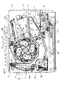
図1は本発明に係る電子写真画像形成装置(以下、画像形成装置という)全体の概略構成を示す縦断面図である。
【0023】
まず、図1を参照して、画像形成装置Aの全体についての概略を説明する。なお、同図に示す画像形成装置Aは4色フルカラーのレーザービームプリンタである。
【0024】
同図に示す画像形成装置Aは、第1の像担持体として、ドラム型の電子写真感光体(以下「感光体ドラム」という)3を備えている。感光体ドラム3は、駆動手段(不図示後述)によって、同図中、反時計回りに回転駆動される。感光体ドラム3の周囲には、その回転方向に従って順に、感光体ドラム3表面を均一に帯電する帯電装置32、画像情報に基づいてレーザービームを照射し感光体ドラム3上の静電潜像を形成する露光手段であるスキャナー部107、静電潜像にトナーを付着させてトナー像として現像する現像装置34、感光体ドラム3上のトナー像が1次転写される第2の像担持体としての中間転写体4、1次転写後の感光体ドラム3表面に残った転写残トナーを除去するクリーニング装置36等が配設されている。
【0025】
ここで感光体ドラム3と帯電装置32、トナーを除去するクリーニング装置36は一体的にカートリッジ化されプロセスカートリッジCを形成し画像形成装置Aの装置本体14に着脱可能なものとなっている。
【0026】
その他に、記録材(第3の像担持体)102を中間転写体4に向けて給送するとともに、記録材102を搬送する給搬送手段37、2次転写後の記録材102にトナー像を定着させる定着部104が配設されている。
【0027】
以下、感光体ドラム3から順に詳述する。
【0028】
感光体ドラム3は、例えば、直径約47mmのアルミニウムシリンダーの外周面に、有機光導電体層(OPC感光体)を塗布して構成したものである。感光体ドラム3は、その両端部を支持部材によって回転自在に支持されており、一方の端部に駆動モータ(不図示)からの駆動力が伝達されることにより、矢印方向に回転駆動される。
【0029】
帯電装置32としては、例えば、特開昭63−149669号公報に示すようないわゆる接触帯電方式のものを使用することができる。帯電部材は、ローラ状に形成された導電性ローラであり、このローラを感光体ドラム3表面に当接させるとともに、このローラに電源(不図示)によって帯電バイアス電圧を印加することにより、感光体ドラム3表面を一様に帯電させるものである。
【0030】
スキャナー部107は、ポリゴンミラー107aを有し、このポリゴンミラー107aには、レーザーダイオード(不図示)によって画像信号に対応する画像光が照射される。ポリゴンミラー107aはスキャナーモータ(不図示)によって高速で回転され、反射した画像光を結像レンズ(不図示)、反射ミラー107b等を介して、帯電済の感光体ドラム3表面を選択的に露光して静電潜像を形成するように構成している。
【0031】
現像装置34は、軸芯2を中心に割出回転可能な現像ロータリー1と、これに搭載された4個の現像器、すなわち、イエロー、マゼンタ、シアン、ブラックの各色のトナーをそれぞれ収納した現像カートリッジDy,Dc,Dm,Dbを備えている。感光体ドラム3上の静電潜像の現像時には、その静電潜像に付着すべき色の所定の現像カートリッジDy,Dc,Dm,Dbの何れか1つが現像位置に配置される。すなわち、現像ロータリー1の外周のギア1aとステッピングモータM0の出力軸端に設けたモータギア1bが噛み合っており、ステッピングモータM0が回転することによる所定の現像カートリッジが現像ロータリー1の割出回転によって感光体ドラム3に対向した現像位置に止まり、さらにその現像カートリッジの現像スリーブDsが感光体ドラム3に対して微小間隙(300μm程度)をもって対向するように位置決めされた後、感光体ドラム3上の静電潜像を現像する。この現像は、次のようにして行う。現像する色に対応する現像カートリッジの容器内のトナーを送り機構によって塗布ローラDpへ送り込み、回転する塗布ローラDp及びトナー規制ブレードDtによって、回転する現像ブレードDsの外周にトナーを薄層塗布し、かつトナーへ電荷を付与(摩擦帯電)する。この現像スリーブDsと、静電潜像が形成された感光体ドラム3との間に現像バイアスを印加することにより、静電潜像にトナー像を付着させてトナー像として現像するものである。又、各現像カートリッジDy,Dc,Dm,Dbの現像スリーブDsには、各現像カートリッジが現像位置に配置されたときに、画像形成装置本体14に設けられた各色現像用高圧電源と接続されるようになっており、各色の現像毎に選択的に電圧が印加される。なお、各現像カートリッジDy,Dc,Dm,Dbは、現像ロータリー1に対して個別に、また現像ロータリー1は装置本体14に対してそれぞれ着脱可能に構成されている。
【0032】
第2の像担持体としての中間転写体4は、感光体ドラム3から順次に1次転写されて重ねられた複数のトナー像を一括して記録材102に2次転写するものである。中間転写体4は、矢印R5方向に走行する中間転写ベルト4aを備えている。本実施の形態の中間転写ベルト4aは、周長約440mmのベルトであり、駆動ローラ4b、2次転写対向ローラ4c、従動ローラ4dの3本のローラにより掛け渡されている。従動ローラ4dに近接して中間転写ベルト4aを感光体ドラム3に押圧する位置と中間転写ベルト4aが感光体ドラム3から離れる位置をとるように後退する押えローラ4jを備えている。中間転写ベルト4aは、駆動ローラ4bの回転によって、矢印R5方向に走行する。さらに、中間転写ベルト4aの外側の所定位置には、中間転写ベルト4aの表面に接離可能なクリーニングユニット4eが設けてあり、後述の記録材102に一括して2次転写後に残った転写残トナーを除去する。クリーニングユニット4eにより、逆の電荷を付与されたトナーは、感光体ドラム3に静電的に付着され、その後、感光体ドラム3用のクリーニング装置36によって回収されるものである。なお、中間転写ベルト4aのクリーニング方法としては、上述の静電クリーニングに限らず、ブレードやファーブラシなどの機械的な方法や、これらを併用したもの等でもよい。
【0033】
クリーニング装置36は、現像装置34によって感光体ドラム3上に現像されたトナーが中間転写ベルト4aに1次転写された後、1次転写されないで感光体ドラム3表面に残ったいわゆる転写残トナーを除去するものである。同図のクリーニング装置36では転写残トナーはクリーニング容器41aの中に蓄積されていく。なお、図1ではクリーニング容器41aは内部は図略されている。
【0034】
給搬送手段37は、給送部101から画像形成部へ記録材102を給送するものであり、複数枚の記録材102が収納されて、画像形成装置本体14の下部に装填される給紙カセット37aを備えている。画像形成時にはピックアップ部材37e、搬送ローラ37bが画像形成動作に応じて駆動回転し、給紙カセット37a内の記録材102を1枚ずつ分離給送するとともに、ガイド板37cによってガイドし、レジストローラ37dを通り中間転写ベルト4aへと給送するものである。
【0035】
定着部104は、記録材102に2次転写された複数のトナー画像を定着させるものであり、図1に示すように、駆動回転する駆動ローラ104aと、これに圧接して記録材102に熱及び圧力を印加する定着ローラ104bとからなる。すなわち、中間転写ベルト4a上のトナーを一括転写させる2次転写ローラ103を通過した記録材102は定着部104を通過する際に駆動ローラ104aで搬送されるとともに、定着ローラ104bによって熱及び圧力を印加される。これにより複数色のトナー像が記録材102の表面に定着される。
【0036】
装置本体14内には開閉カバー11を閉じると開閉カバー11に設けたドッグ11bに押されて閉成するインターロック電源スイッチ109が設けられている。開閉カバー11を開くとインターロック電源スイッチ109が開成して、装置本体14の高圧電源部から現像バイアスを現像カートリッジDy,Dc,Dm,Dbへ加えるための高圧給電用金属部品108等への給電が行われなくなるようになって入る。
【0037】
次に上述構成の画像形成装置の画像形成動作について説明する。
【0038】
中間転写ベルト4aの回転と同期して感光体ドラム3を図1の矢印方向(反時計回り)に回転させ、この感光体ドラム3表面を帯電装置32によって均一に帯電するとともに、スキャナー部107によってイエロー画像の光照射を行い、感光体ドラム3上にイエローの静電潜像を形成する。この静電潜像形成と同時に現像装置34を駆動してイエローの現像カートリッジDyを現像位置に配置し、感光体ドラム3上の静電潜像にイエロートナーが付着するように感光体ドラム3の帯電極性と同極性でほぼ同電位の電圧を印加して静電潜像にイエローのトナーを付着させて現像する。1次転写ローラ(従動ローラ)4dにトナーと逆極性の電圧を印加して感光体ドラム3上のイエローのトナー像を中間転写ベルト4a上に1次転写する。
【0039】
上述のようにしてイエロートナー像の1次転写が終了すると、次の現像カートリッジDcが回転移動し、感光体ドラム3に対向する現像位置に位置決めされ、イエローの場合と同様にしてシアン、マゼンタ、そしてブラックの各色について、静電潜像の形成、現像、1次転写を順次に行い、中間転写ベルト4a上に4色のトナー像を重ね合わせる。これらトナー像を、給搬送手段37から供給された記録材102に一括して2次転写する。
【0040】
そして2次転写後の記録材102を定着部104に搬送して、ここで、トナー像の定着を行った後、排出ローラ105及び図示矢印方向に移動するベルト106aと巻掛けたベルト106aで駆動される排出ローラ106bによって画像形成装置本体14外部の排紙トレイ40上に排出して画像形成を終了するものである。
【0041】
上述のように構成された現像装置34は各現像カートリッジDy,Dc,Dm,Dbを現像ロータリー1の放射方向から着脱されるようになっている。そして、排紙トレイ40の一部を構成される開閉カバー11を装置本体14へ取着しているヒンジ11aを中心にして図1において反時計方向に回転すると、開口部が生じ現像カートリッジのDy,Dc,Dm,Dbの1つが現われる。現像カートリッジDy,Dc,Dm,Dbは現像ロータリー1の周方向を四等配し且つ軸芯2から等距離の位置に同じ姿勢で取り外し可能に装着されている。従って、現像ロータリー1の割り出しを行う図外の操作ボタンを押すと、現像ロータリー1は割出回転し、現像カートリッジDy,Dc,Dm,Dbのうちの所望の1つを上述の開閉カバー11の位置へ回動できる。
【0042】
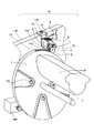
次に、本発明の主要部分について説明する。図3に示すように現像ロータリー1の外周に形成されたギア1aに、メカニカルブレーキ機構Mに構成された3つのギアのうち第1ギア5が常時噛み合っている。この第1ギア5は装置本体14の側板14aに小ねじ13aで固定されたブラケット13に固定した軸13bに回転自在に嵌合している。又第2ギア6、第3ギア7は第1ギア5と常時噛み合っている。第2ギア6はブラケット13に固定した固定軸13cに回転自在に嵌合している。第3ギア7は第1ギア5の中心付近を中心にして揺動する揺動部材8に固定された固定軸7aに回転自在に嵌合している。さらに第2ギア6、第3ギア7同軸上にはそれぞれのギアの歯先円直径よりも大きな直径をもつ摩擦係数の大きな弾性体のローラ9がギア6,7と夫々一体に形成されている。ローラ9の外周部材は例えばゴムである。
【0043】
又第2ギア6、第3ギア7に一体に形成されたローラ9は、お互いが接触する方向にばね等の付勢部材によって付勢されている。即ち、引張りコイルばね10がブラケット13と揺動部材8間に張設されている。
【0044】
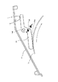
図4に示すように現像カートリッジDy,Dc,Dm,Dbを交換するためにユーザーが開ける開閉カバー11には突起部12が設けられている。突起部12は開閉カバー11の閉まる動作によって、前記メカニカルブレーキ機構Mの揺動部材8のカム部8aに接して引張りコイルばね10のばね力に抗して揺動部材8を固定軸5aを中心に時計回りに回動させることで、前記第2ギア6、第3ギア7に一体に形成されたローラ9の接触が離れ、前記第1ギア5、第2ギア6、第3ギア7は無負荷状態となり回転自在となることで、現像ロータリー1が回転可能状態となる。反対に現像カートリッジDy,Dc,Dm,Dbを交換するため開閉カバー11の開く動作によって、開閉カバー11の突起部12がメカニカルブレーキ機構Mの揺動部材8から離れ、引張りコイルばね10のばね力によって第2ギア6、第3ギア7に一体に形成されたローラ9は互いに接触する方向に付勢されるため前記第1、第2、第3ギア5,6,7は全て回転不能となる。そのため現像ロータリー1の外周に形成されたギア1aが回転不可能な状態となるため現像ロータリー1の回転運動が停止する。
【0045】
これにより、開閉カバー11の開閉動作に連動して現像ロータリー1の回転を機械的に停止することができる。そのため装置本体14のインターロック電源スイッチ109を切ることができるようになった。
【0046】
そのため現像ロータリー1への高圧電流が遮断されるため、現像カートリッジへの高圧給電用金属部品108の周りに複雑な形状のカバーを設置する必要がなくなり、装置が大きくなるといったことがなくなった。又従来、ステッピングモータなどの駆動源を電気的に励磁させることで現像ロータリー1の回転を固定するといった方法で生じていた、長時間の放置におけるモータの昇温によってその励磁力が著しく弱まり、ユーザーが現像カートリッジを挿入しようとしたとき、現像ロータリーが回転してしまい、現像カートリッジがうまく挿入できないという重大な欠点も回避できた。
【0047】
〔実施の形態2〕
次に本発明の他の実施の形態に係る画像形成装置について図4を参照して説明する。
【0048】
揺動部材8は、現像ロータリー1が回転することで発生する回転モーメントによって第3ギア7と一体に形成されているローラ9bが第2ギア6に一体に形成されたローラ9aに押し付けられるような位置にその回動中心がある。即ち固定軸5aが揺動部材8に嵌合して入る。
【0049】
このように構成した場合、現像ロータリー1が図4において図示矢印の時計方向に回転しようとする際、ギア1aと第1ギア5間の歯荷重は第1ギア5を支持する固定軸5aで支持される。そして第1ギア5が図示矢印の反時計方向に回転しようとすると、第1ギア5と第3ギア7間の歯荷重は両ギア5,7の噛み合いの作用線方向に働くから、この歯荷重に平行な力が矢印イのように第3ギア7を支持する固定軸7aに働く。この固定軸7aは揺動部材8に固定されているため、揺動部材8を固定軸5aを中心に反時計回りに回転しようとするモーメントにより、ローラ9bは、ローラ9aに押圧される。そして、夫々弾性部材のローラ9a,9bは夫々の接触部において、各々の周面が反対方向に移動しようとしても、現像ロータリー1が回動しようとする力でローラ9a,9bは余計に押しつけられることになる。従って現像ロータリー1へ与える制動力を充分確保できる。そして、引張りコイルばね10のばね力を小さくできるので、揺動部材8が開閉カバー11の突起部12を押す力を小さくできる。また、この実施の形態2においては第3ギア7を支持する固定軸7aが第1ギア5を支持する固定軸5aを中心に回動するので第1、第3ギア5,7の噛み合いが一定の軸間距離で行なわれる。
【0050】
〔実施の形態3〕
次に本発明の実施の形態3に係る画像形成装置について、図5を参照して説明する。
【0051】
装置本体14にはピン14bでもってレバー21が揺動自在に支持されている。レバー21の一端には現像ロータリー1のギア1aと噛合し得るギア形状部分21aを有し、開閉カバー11が閉じると開閉カバー11の突起12で押される他端を有している。このレバー21は開閉カバー11が閉じて他端が突起12で押されてギア形状部21aが現像ロータリー1のギア1aとの噛み合いが外れる位置と、開閉カバー11が開くとギア1aからギア形状部21aが噛合う位置と、を取り得るようになっている。そして、引張コイルばね22の一端がレバー21のピン14bで支持される位置よりもギア形状部21a側に係止され、他端が装置本体14に係止され、レバー21は反時計回りに回転力を受けて、ギア形状部21aが現像ロータリー1のギア1aと噛み合い得るように付勢されている。
【0052】
尚、インターロック電源スイッチの関係は図示されないが実施の形態1と同様である。
【0053】
開閉カバー11が閉じられているときは、突起部12はレバー21の他端を引張コイルばね22のばね力に抗して回動していて現像ロータリー1のギア1aとレバー21のギア形状部21aは噛み合いが外れているので現像ロータリー1は回転可能であり、この状態で画像形成が行われる。
【0054】
現像カートリッジDy,Dc,Dm,Dbを交換する際は、開閉カバー11を開けると突起部12で押さえられていたレバー21は突起部12が上方へ去ることにより、突起部12で押えられていた端部が上方へ移動可能となり、レバー21が引張コイルばね22のばね力によりピン14bを中心に反時計回りに揺動し、ギア形状部21aが現像ロータリー1のギア1aに噛み合い、現像ロータリー1は固定される。それと共に現像ロータリー1の電源が電源スイッチの開成により切られる。ここで現像カートリッジDy,Dc,Dm,Dbの何れか1つの交換が行われる。
【0055】
現像カートリッジ交換後に開閉カバー11を閉めると突起部12はレバー21の他端を押し、ギア1aとギア形状部21aの噛み合いが外れる。
【0056】
上記レバー21の付勢は引張コイルばね22と併せて又は引張コイルばね22なしでレバー21のギア形状部21aのある一端側の一次モーメントを、他端側の一次モーメントよりも大としておいても有効である。
【0057】
本実施の形態ではギア形状部21aを現像ロータリー1のギア1aに噛み合せたので非常に強力に現像ロータリー1が固定される。このギア形状部21aは突起であればよいのでギア状でなくともよく、又複数の突起でなく、単数でも可能である。
【0058】
なお、本実施の形態によれば現像ロータリー1は四割出回転、即ち90度毎に回転する。又現像ロータリー1は図示されない割出回転位置検出手段を備えている。そこで本実施の形態によれば現像ロータリー1のギア1aの歯数は例えば4n(nは正の整数)とする。
【0059】
以上説明した構成により非常に安価な方法で現像カートリッジDy,Dc,Dm,Dbを交換するためにユーザーが開ける開閉カバー11の動きに連動して現像ロータリーの回転に制動を与えることができる。
【0060】
以上説明したように、本実施例によれば、簡単なブレーキ機構の設置によって開閉カバーの開閉動作に連動して現像ロータリーの回転を機械的に停止することができる。そのため開閉カバーの開閉動作に連動して装置本体のインターロック電源スイッチを切ることができるようになった。
【0061】
そのため現像ロータリーへの高圧電流が遮断される。またステッピングモータなどの駆動源を電気的に励磁させることで現像ロータリーの回転を固定するといった方法で生じていた、長時間の放置におけるモータの昇温によってその励磁力が著しく弱まり、現像カートリッジを挿入する際に、現像ロータリーが回転してしまい、現像カートリッジがうまく挿入できないということが回避できた。
【発明の効果】
以上説明したように、本発明によれば、簡単な構成で、開閉部材の開閉動作に連動して現像ロータリーの回転を機械的に停止することができる。そのため、現像ロータリーが回転しないように、駆動モータを電気的に励磁する必要がなくなる。
【図面の簡単な説明】
図面は何れも本発明実施の形態を示し、
【図1】本発明の画像形成装置の現像ロータリーのブレーキ解除時を示す縦断面図である。
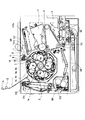
【図2】本発明の画像形成装置の現像ロータリーのブレーキ作動時を示す縦断面図である。
【図3】本発明のブレーキ機構の斜視図である。
【図4】本発明のブレーキ機構の正面図である。
【図5】本発明の他の実施の形態2の正面図である。
【符号の説明】
A…画像形成装置
C…プロセスカートリッジ
Dy…イエロー現像カートリッジ
Dc…シアン現像カートリッジ
Dm…マゼンタ現像カートリッジ
Db…ブラック現像カートリッジ
Ds…現像スリーブ
Dp…塗布ローラ
Dt…トナー規制ブレード
M…メカニカルブレーキ機構
1…現像ロータリー 1a…ロータリーの外周に形成されたギア 1b…モータギア
2…ロータリーの軸芯
3…感光体ドラム
4…中間転写体 4a…中間転写ベルト 4b…駆動ローラ 4c…2次転写対向ローラ 4d…従動ローラ 4e…クリーニングユニット 4j…押えローラ
5…メカニカルブレーキ機構Mに構成された第1ギア 5a…固定軸
6…メカニカルブレーキ機構Mに構成された第2ギア
7…メカニカルブレーキ機構Mに構成された第1ギア 7a…固定軸
8…第1ギア5を中心にして回動する揺動部材
9,9a,9b…第2ギア6、第3ギア7の中心軸のそれぞれ同軸上に、ギアと一体に形成されたそれぞれのギアの歯先円直径よりも大きな直径をもつ摩擦係数の大きな弾性体のローラ
10…引張りコイルばね
11…現像カートリッジDy,Dc,Dm,Dbを交換するために開ける開閉カバー 11a…ヒンジ 11b…ドッグ
12…突起部
13…ブラケット 13a…小ねじ 13b…軸 13c…固定軸
14…装置本体 14a…側板 14b…ピン
21…レバー 21a…ギア形状部
22…引張りコイルばね
32…帯電装置
34…現像装置
36…クリーニング装置
37…給搬送手段 37a…給紙カセット 37b…搬送ローラ 37c…ガイド板 37d…レジストローラ 37e…ピックアップ部材
40…排紙トレイ
101…給送部
102…記録材
103…2次転写ローラ
104…定着部 104a…駆動ローラ 104b…定着ローラ
105…排出ローラ
106…排出部 106a…ベルト 106b…排出ローラ
107…スキャナー部 107a…ポリゴンミラー 107b…反射ミラー
108…高圧給電用金属部品
109…装置本体のインターロック電源スイッチ
MO…ステッピングモータ[0001]
BACKGROUND OF THE INVENTION
The present invention relates to an electrophotographic image forming apparatus such as a copying machine or a laser beam printer. More specifically, a plurality of developing cartridges are used to form a toner image for each color on an electrophotographic photosensitive drum, and a plurality of intermediate transfer members are formed. The present invention relates to an electrophotographic image forming apparatus that forms a color toner image and forms a color image on a recording material.
[0002]
[Problems to be solved by the invention]
The present invention is a further development of the prior art described below.
[0003]
An object of the present invention is to provide an electrophotographic image forming apparatus having a developing device carrying a developing cartridge by a developing rotary, and an electronic device having a mechanical brake mechanism that can fix the developing rotary without using electric power when replacing the developing cartridge. A photographic image forming apparatus is provided.
[0004]
[Means for Solving the Problems]
The first invention according to the present application is In an electrophotographic image forming apparatus that forms an image on a recording medium, a drive motor; An electrophotographic photosensitive drum, a rotatable developing rotary, a mounting portion for detachably mounting a developing cartridge for developing an electrostatic latent image formed on the electrophotographic photosensitive drum, and the developing rotary of To move the developer cartridge provided on the outer periphery Said Drive motor From of A development rotary having a rotary gear for receiving a driving force; An opening for mounting the developing cartridge to the mounting portion, an opening / closing member capable of taking an open position for opening the opening and a closed position for closing the opening; It is provided rotatably in the main body of the electrophotographic image forming apparatus. The A first gear meshing with the rotary gear, and a rotatable on the apparatus main body. The A second gear that meshes with the first gear; a third gear that meshes with the first gear; and a first roller that rotates integrally with the second gear, the diameter of the tip circle of the second gear. A first roller having a larger diameter, a second roller rotating integrally with the third gear, the second roller having a diameter larger than the diameter of the tip circle of the third gear, and the device Provided in the body Further, the third gear and the second roller are rotatably supported and moved in conjunction with the opening / closing member. When the opening / closing member is located at the open position, the second roller is moved to the first roller. In When the contact position to be contacted and the opening / closing member are located at the closed position, the second roller is moved to the first roller. From An electrophotographic apparatus comprising: a swinging member that can be separated; and a biasing member that biases the swinging member in a direction in which the second roller contacts the first roller. An image forming apparatus.
[0005]
The second invention according to the present application is Further, the apparatus main body includes a fixing member in which the first gear, the first roller, and the second gear are rotatably provided. The electrophotographic image forming apparatus according to the first aspect of the present invention.
[0006]
The third invention related to this application is The fixing member, the swinging member supported by the fixing member so as to be swingable, and the biasing member are configured as an integral unit and are fixed to the apparatus main body. An electrophotographic image forming apparatus according to a second aspect of the present invention.
[0007]
The fourth invention related to this application is In an electrophotographic image forming apparatus that forms an image on a recording medium, a drive motor; An electrophotographic photosensitive drum, a rotatable developing rotary, a mounting portion for detachably mounting a developing cartridge for developing an electrostatic latent image formed on the electrophotographic photosensitive drum, and the developing rotary of To move the developer cartridge provided on the outer periphery Said Drive motor From of A development rotary having a rotary gear for receiving a driving force; An opening for mounting the developing cartridge to the mounting portion, an opening / closing member capable of taking an open position for opening the opening and a closed position for closing the opening, and movement in conjunction with the opening / closing member A meshing member that engages with the rotary gear when the open / close member is in the open position; Development rotary rotation Do And when the opening / closing member is located at the closed position, the engagement with the rotary gear is released, Development rotary rotation Do An electrophotographic image forming apparatus characterized by having a release position that permits the engagement, and a meshing member that can take the position.
[0008]
The fifth invention related to this application is The meshing member is a projection that meshes with the rotary gear. An electrophotographic image forming apparatus according to a fourth aspect of the present invention.
[0009]
The sixth invention according to this application is The electrophotographic image forming apparatus includes a biasing member for biasing the meshing member to the meshing position when the opening / closing member is in the open position. An electrophotographic image forming apparatus according to the fifth invention.
[0016]
[Prior art]
Conventionally, toner images are formed one by one on an electrophotographic photosensitive drum using a plurality of developing cartridges, the toner images are sequentially transferred to an intermediate transfer member, and a plurality of color toner images are superimposed on the intermediate transfer member to form an intermediate image. In an electrophotographic image forming apparatus that forms a color image by transferring a color image on a transfer member onto a recording material, a plurality of developing cartridges are installed in a developing rotary that rotates around a single axis by a driving source. Many electrophotographic image forming apparatuses employ a method in which the developing rotary is indexed and rotated so that the developing cartridge faces the electrophotographic photosensitive drum to form toner images of a plurality of colors on the electrophotographic photosensitive drum.
[0017]
In such an apparatus, it is necessary to stop the rotation operation of the developing rotary in order to replace the developing cartridge. For this reason, in general, there is a brake mechanism in which the rotation operation of the developing rotary is stopped or the stop is released in conjunction with the operation of the cover that is opened for replacing the developing cartridge.
[0018]
The brake is generally a method in which the rotation of the developing rotary is fixed by electrically exciting a drive source such as a stepping motor that rotates the developing rotary.
[0019]
DETAILED DESCRIPTION OF THE INVENTION
[Description of Embodiments of the Invention]
Hereinafter, embodiments of the present invention will be described in detail with reference to the drawings.
[0020]
In the following description, the short direction of the process cartridge C is the direction in which the process cartridge C is attached to and detached from the apparatus
[0021]
(Embodiment 1)
Embodiments of the present invention will be described below with reference to the drawings.
[0022]
{Overall configuration of image forming apparatus}
FIG. 1 is a longitudinal sectional view showing a schematic configuration of an entire electrophotographic image forming apparatus (hereinafter referred to as an image forming apparatus) according to the present invention.
[0023]
First, an outline of the entire image forming apparatus A will be described with reference to FIG. The image forming apparatus A shown in the figure is a four-color full-color laser beam printer.
[0024]
The image forming apparatus A shown in FIG. 1 includes a drum-type electrophotographic photosensitive member (hereinafter referred to as “photosensitive drum”) 3 as a first image carrier. The
[0025]
Here, the
[0026]
In addition, the recording material (third image carrier) 102 is fed toward the intermediate transfer member 4, and the feeding / conveying
[0027]
Hereinafter, the
[0028]
The
[0029]
As the charging device 32, for example, a so-called contact charging method as shown in Japanese Patent Laid-Open No. 63-149669 can be used. The charging member is a conductive roller formed in a roller shape. The roller is brought into contact with the surface of the
[0030]
The
[0031]
The developing
[0032]
The intermediate transfer member 4 as a second image carrier is a member that secondary-transfers a plurality of toner images that are sequentially primary-transferred from the
[0033]
The
[0034]
The feeding / conveying
[0035]
The fixing
[0036]
An
[0037]
Next, an image forming operation of the image forming apparatus configured as described above will be described.
[0038]
The
[0039]
When the primary transfer of the yellow toner image is completed as described above, the next developing cartridge Dc rotates and is positioned at the developing position facing the
[0040]
Then, the
[0041]
In the developing
[0042]
Next, the main part of the present invention will be described. As shown in FIG. 3, the first gear 5 of the three gears configured in the mechanical brake mechanism M is always meshed with the
[0043]
The rollers 9 formed integrally with the second gear 6 and the third gear 7 are biased by a biasing member such as a spring in a direction in which they contact each other. That is, the
[0044]
As shown in FIG. 4, a
[0045]
Thereby, the rotation of the developing rotary 1 can be mechanically stopped in conjunction with the opening / closing operation of the opening /
[0046]
For this reason, since the high-voltage current to the developing
[0047]
[Embodiment 2]
Next, an image forming apparatus according to another embodiment of the present invention will be described with reference to FIG.
[0048]
The swing member 8 is configured such that a
[0049]
In this configuration, when the developing rotary 1 tries to rotate in the clockwise direction indicated by the arrow in FIG. 4, the tooth load between the
[0050]
[Embodiment 3]
Next, an image forming apparatus according to
[0051]
A
[0052]
The relationship of the interlock power switch is not shown, but is the same as in the first embodiment.
[0053]
When the opening /
[0054]
When the developing cartridges Dy, Dc, Dm, and Db were replaced, the
[0055]
When the opening /
[0056]
The bias of the
[0057]
In this embodiment, since the gear-shaped
[0058]
According to the present embodiment, the developing
[0059]
With the configuration described above, the rotation of the developing rotary can be braked in conjunction with the movement of the opening /
[0060]
As described above, according to this embodiment, the rotation of the developing rotary can be mechanically stopped in conjunction with the opening / closing operation of the opening / closing cover by installing a simple brake mechanism. Therefore, the interlock power switch of the main unit can be turned off in conjunction with the opening / closing operation of the opening / closing cover.
[0061]
Therefore, the high voltage current to the development rotary is interrupted. In addition, the excitation force is significantly weakened due to the temperature rise of the motor when left unattended for a long time, which was caused by the method of fixing the rotation of the developing rotary by electrically exciting a drive source such as a stepping motor. In this case, it was possible to avoid that the developing rotary was rotated and the developing cartridge could not be inserted well.
【The invention's effect】
As described above, according to the present invention, the rotation of the developing rotary can be mechanically stopped in a simple configuration in conjunction with the opening / closing operation of the opening / closing member. Therefore, it is not necessary to electrically excite the drive motor so that the development rotary does not rotate.
[Brief description of the drawings]
Each drawing shows an embodiment of the present invention,
FIG. 1 is a longitudinal sectional view showing a state where a brake of a developing rotary of an image forming apparatus of the present invention is released.
FIG. 2 is a longitudinal cross-sectional view showing the developing rotary of the image forming apparatus of the present invention when a brake is operated.
FIG. 3 is a perspective view of the brake mechanism of the present invention.
FIG. 4 is a front view of the brake mechanism of the present invention.
FIG. 5 is a front view of another
[Explanation of symbols]
A: Image forming apparatus
C ... Process cartridge
Dy ... Yellow developer cartridge
Dc: Cyan developing cartridge
Dm ... Magenta developer cartridge
Db ... Black developing cartridge
Ds ... Development sleeve
Dp ... Application roller
Dt ... Toner regulating blade
M ... Mechanical brake mechanism
DESCRIPTION OF
2 ... Rotary shaft
3 ... Photosensitive drum
4 ...
5 ... 1st gear comprised in the mechanical
6 ... The second gear configured in the mechanical brake mechanism M
7 ... 1st gear comprised in the mechanical
8: Swing member that rotates around the first gear 5
9, 9a, 9b... Elasticity with a large friction coefficient having a diameter larger than the diameter of the tip circle of each gear formed integrally with the gear on the same axis of the center axis of each of the second gear 6 and the third gear 7. Body roller
10 ... Tension coil spring
11: Open / close cover opened to replace developing cartridges Dy, Dc, Dm, Db 11a ...
12 ... Protrusions
13 ...
14 ... device
21 ...
22 ... Tension coil spring
32 ... Charging device
34. Developing device
36 ... Cleaning device
37... Feeding means 37 a.
40 ... Output tray
101 ... feeding section
102 ... Recording material
103 ... Secondary transfer roller
104 ... Fixing
105 ... discharge roller
106 ...
107 ...
108 ... Metal parts for high-voltage power supply
109 ... Interlock power switch of the device body
MO ... Stepping motor
Claims (6)
駆動モータと、
電子写真感光体ドラムと、
回転可能な現像ロータリーであって、前記電子写真感光体ドラムに形成された静電潜像を現像する現像カートリッジを取り外し可能に装着するための装着部と、前記現像ロータリーの外周に設けられた、前記現像カートリッジを移動させるために前記駆動モータからの駆動力を受けるロータリーギアと、を有する現像ロータリーと、
前記装着部に対して前記現像カートリッジを装着するための開口と、 前記開口を開放する開位置と前記開口を閉鎖する閉位置とを取り得る開閉部材と、
前記電子写真画像形成装置の装置本体に回転自在に設けられた、前記ロータリーギアと噛合する第1ギアと、
前記装置本体に回転自在に設けられた、前記第1ギアと噛合する第2ギアと、
前記第1ギアと噛合する第3ギアと、
前記第2ギアと一体で回転する第1ローラであって、前記第2ギアの歯先円の直径よりも大きな直径を有する第1ローラと、
前記第3ギアと一体で回転する第2ローラであって、前記第3ギアの歯先円の直径よりも大きな直径を有する第2ローラと、
前記装置本体に設けられた、前記第3ギアおよび前記第2ローラを回転自在に支持し、前記開閉部材と連動して移動する揺動部材であって、前記開閉部材が前記開位置に位置する際には、前記第2ローラを前記第1ローラに接触させる接触位置と、前記開閉部材が前記閉位置に位置する際には、前記第2ローラを前記第1ローラから離間させる離間位置と、をとり得る揺動部材と、
前記揺動部材を前記第2ローラが前記第1ローラと接触する方向に付勢する付勢部材と、
を有することを特徴とする電子写真画像形成装置。In an electrophotographic image forming apparatus for forming an image on a recording medium,
A drive motor;
An electrophotographic photosensitive drum;
A rotatable developing rotary, a mounting portion for detachably mounting a developing cartridge for developing an electrostatic latent image formed on the electrophotographic photosensitive drum, and an outer periphery of the developing rotary; A rotary gear that receives a driving force from the driving motor to move the developing cartridge;
An opening for mounting the developing cartridge to the mounting portion; an opening / closing member capable of taking an open position for opening the opening and a closed position for closing the opening;
A first gear meshing with the rotary gear, which is rotatably provided in the main body of the electrophotographic image forming apparatus;
A second gear that is rotatably provided in the apparatus main body and meshes with the first gear;
A third gear meshing with the first gear;
A first roller that rotates integrally with the second gear, the first roller having a diameter larger than the diameter of a tip circle of the second gear;
A second roller that rotates integrally with the third gear, the second roller having a diameter larger than the diameter of the tip circle of the third gear;
A swing member provided in the apparatus main body, rotatably supporting the third gear and the second roller, and moving in conjunction with the opening / closing member, wherein the opening / closing member is located at the open position. A contact position for contacting the second roller with the first roller, and a separation position for separating the second roller from the first roller when the opening / closing member is located at the closed position; A swinging member capable of taking
A biasing member that biases the swing member in a direction in which the second roller contacts the first roller;
An electrophotographic image forming apparatus comprising:
前記第1ギア、前記第1ローラ、及び、前記第2ギアが回転自在に設けられた固定部材を有することを特徴とする請求項1に記載の電子写真画像形成装置。Furthermore, the device body is
The electrophotographic image forming apparatus according to claim 1, further comprising a fixing member on which the first gear, the first roller, and the second gear are rotatably provided.
駆動モータと、
電子写真感光体ドラムと、
回転可能な現像ロータリーであって、前記電子写真感光体ドラムに形成された静電潜像を現像する現像カートリッジを取り外し可能に装着するための装着部と、前記現像ロータリーの外周に設けられた、前記現像カートリッジを移動させるために前記駆動モータからの駆動力を受けるロータリーギアと、を有する現像ロータリーと、
前記装着部に対して前記現像カートリッジを装着するための開口と、 前記開口を開放する開位置と前記開口を閉鎖する閉位置とを取り得る開閉部材と、
前記開閉部材に連動して移動する噛み合い部材であって、前記開閉部材が前記開位置に位置する際には、前記ロータリーギアと噛合して前記現像ロータリーが回転するのを阻止する噛合位置と、前記開閉部材が前記閉位置に位置する際には、前記ロータリーギアとの噛合が解除されて、前記現像ロータリーが回転するのを許容する解除位置と、をとり得る噛み合い部材と、
を有することを特徴とする電子写真画像形成装置。In an electrophotographic image forming apparatus for forming an image on a recording medium,
A drive motor;
An electrophotographic photosensitive drum;
A rotatable developing rotary, a mounting portion for detachably mounting a developing cartridge for developing an electrostatic latent image formed on the electrophotographic photosensitive drum, and an outer periphery of the developing rotary; A rotary gear that receives a driving force from the driving motor to move the developing cartridge;
An opening for mounting the developing cartridge to the mounting portion; an opening / closing member capable of taking an open position for opening the opening and a closed position for closing the opening;
A meshing member that moves in conjunction with the opening and closing member, and when the opening and closing member is in the open position, a meshing position that meshes with the rotary gear and prevents the developing rotary from rotating; When the opening / closing member is located at the closed position, a meshing member capable of taking a release position where the meshing with the rotary gear is released and the development rotary is allowed to rotate,
An electrophotographic image forming apparatus comprising:
Priority Applications (1)
| Application Number | Priority Date | Filing Date | Title |
|---|---|---|---|
| JP08445897A JP3720522B2 (en) | 1997-03-18 | 1997-03-18 | Electrophotographic image forming apparatus |
Applications Claiming Priority (1)
| Application Number | Priority Date | Filing Date | Title |
|---|---|---|---|
| JP08445897A JP3720522B2 (en) | 1997-03-18 | 1997-03-18 | Electrophotographic image forming apparatus |
Publications (2)
| Publication Number | Publication Date |
|---|---|
| JPH10260566A JPH10260566A (en) | 1998-09-29 |
| JP3720522B2 true JP3720522B2 (en) | 2005-11-30 |
Family
ID=13831192
Family Applications (1)
| Application Number | Title | Priority Date | Filing Date |
|---|---|---|---|
| JP08445897A Expired - Lifetime JP3720522B2 (en) | 1997-03-18 | 1997-03-18 | Electrophotographic image forming apparatus |
Country Status (1)
| Country | Link |
|---|---|
| JP (1) | JP3720522B2 (en) |
Families Citing this family (2)
| Publication number | Priority date | Publication date | Assignee | Title |
|---|---|---|---|---|
| US7190921B2 (en) | 2003-07-31 | 2007-03-13 | Brother Kogyo Kabushiki Kaisha | Developing cartridge, photosensitive member cartridge, process unit, and image forming apparatus |
| JP4911236B2 (en) | 2009-08-28 | 2012-04-04 | ブラザー工業株式会社 | Image forming apparatus |
-
1997
- 1997-03-18 JP JP08445897A patent/JP3720522B2/en not_active Expired - Lifetime
Also Published As
| Publication number | Publication date |
|---|---|
| JPH10260566A (en) | 1998-09-29 |
Similar Documents
| Publication | Publication Date | Title |
|---|---|---|
| JP5383879B2 (en) | Image forming apparatus | |
| JP2006349763A (en) | Image forming apparatus | |
| JPH06289666A (en) | Electrophotographic device | |
| JP3517475B2 (en) | Image forming device | |
| JP3984978B2 (en) | Process cartridge and electrophotographic image forming apparatus | |
| JP3720522B2 (en) | Electrophotographic image forming apparatus | |
| JPH11125985A (en) | Fixing device and image forming device | |
| JP3285741B2 (en) | Color image forming apparatus and process cartridge | |
| JP2001194977A (en) | Process cartridge and image forming device | |
| JP4783036B2 (en) | Positioning mechanism for photoreceptor and developing roller and image forming apparatus provided with the same | |
| JP2705161B2 (en) | Transfer drum drive mechanism | |
| JP3036144B2 (en) | Electrophotographic equipment | |
| JP2715594B2 (en) | Image forming apparatus and process cartridge | |
| JP2006171360A (en) | Image forming apparatus | |
| JP4717274B2 (en) | Color image forming apparatus | |
| JP4978029B2 (en) | Image forming apparatus | |
| JP2004085901A (en) | Developer amount detecting device, developing device and electrophotographic image forming apparatus | |
| JP3465985B2 (en) | Image forming device | |
| JP3266474B2 (en) | Image forming device | |
| JP2004333929A (en) | Image forming apparatus | |
| JPH07199768A (en) | Image forming device | |
| KR100580220B1 (en) | Rotating force clutch apparatus of image forming apparatus | |
| JP3847967B2 (en) | Electrophotographic image forming apparatus | |
| JPH08234588A (en) | Image forming device and transfer device | |
| JPH10239930A (en) | Color image forming device |
Legal Events
| Date | Code | Title | Description |
|---|---|---|---|
| A131 | Notification of reasons for refusal |
Free format text: JAPANESE INTERMEDIATE CODE: A131 Effective date: 20050118 |
|
| A521 | Request for written amendment filed |
Free format text: JAPANESE INTERMEDIATE CODE: A523 Effective date: 20050322 |
|
| TRDD | Decision of grant or rejection written | ||
| A01 | Written decision to grant a patent or to grant a registration (utility model) |
Free format text: JAPANESE INTERMEDIATE CODE: A01 Effective date: 20050906 |
|
| A61 | First payment of annual fees (during grant procedure) |
Free format text: JAPANESE INTERMEDIATE CODE: A61 Effective date: 20050908 |
|
| R150 | Certificate of patent or registration of utility model |
Free format text: JAPANESE INTERMEDIATE CODE: R150 |
|
| FPAY | Renewal fee payment (event date is renewal date of database) |
Free format text: PAYMENT UNTIL: 20090916 Year of fee payment: 4 |
|
| FPAY | Renewal fee payment (event date is renewal date of database) |
Free format text: PAYMENT UNTIL: 20090916 Year of fee payment: 4 |
|
| FPAY | Renewal fee payment (event date is renewal date of database) |
Free format text: PAYMENT UNTIL: 20100916 Year of fee payment: 5 |
|
| FPAY | Renewal fee payment (event date is renewal date of database) |
Free format text: PAYMENT UNTIL: 20100916 Year of fee payment: 5 |
|
| FPAY | Renewal fee payment (event date is renewal date of database) |
Free format text: PAYMENT UNTIL: 20110916 Year of fee payment: 6 |
|
| FPAY | Renewal fee payment (event date is renewal date of database) |
Free format text: PAYMENT UNTIL: 20110916 Year of fee payment: 6 |
|
| FPAY | Renewal fee payment (event date is renewal date of database) |
Free format text: PAYMENT UNTIL: 20120916 Year of fee payment: 7 |