JP3720439B2 - Data input / output control apparatus and data input / output control method - Google Patents
Data input / output control apparatus and data input / output control method Download PDFInfo
- Publication number
- JP3720439B2 JP3720439B2 JP33035895A JP33035895A JP3720439B2 JP 3720439 B2 JP3720439 B2 JP 3720439B2 JP 33035895 A JP33035895 A JP 33035895A JP 33035895 A JP33035895 A JP 33035895A JP 3720439 B2 JP3720439 B2 JP 3720439B2
- Authority
- JP
- Japan
- Prior art keywords
- data
- output control
- data input
- server
- control device
- Prior art date
- Legal status (The legal status is an assumption and is not a legal conclusion. Google has not performed a legal analysis and makes no representation as to the accuracy of the status listed.)
- Expired - Fee Related
Links
Images


Classifications
-
- H—ELECTRICITY
- H04—ELECTRIC COMMUNICATION TECHNIQUE
- H04L—TRANSMISSION OF DIGITAL INFORMATION, e.g. TELEGRAPHIC COMMUNICATION
- H04L9/00—Cryptographic mechanisms or cryptographic arrangements for secret or secure communications; Network security protocols
- H04L9/40—Network security protocols
-
- H—ELECTRICITY
- H04—ELECTRIC COMMUNICATION TECHNIQUE
- H04L—TRANSMISSION OF DIGITAL INFORMATION, e.g. TELEGRAPHIC COMMUNICATION
- H04L67/00—Network arrangements or protocols for supporting network services or applications
- H04L67/34—Network arrangements or protocols for supporting network services or applications involving the movement of software or configuration parameters
Landscapes
- Engineering & Computer Science (AREA)
- Computer Security & Cryptography (AREA)
- Computer Networks & Wireless Communication (AREA)
- Signal Processing (AREA)
- Facsimiles In General (AREA)
- Record Information Processing For Printing (AREA)
- Laser Beam Printer (AREA)
Abstract
Description
【0001】
【発明の属する技術分野】
本発明は、ネットワーク上で複数のクライアントユーザーが、スキャナ機能或いはプリント機能を共有することを可能とするネットワークシステムにおけるデータ入出力制御装置及びデータ入出力制御方法及びスキャナ/プリンタサーバーシステムに関するものである。
【0002】
【従来の技術】
近年、複数のコンピュータをネットワーク上につなぎ、データの共有化、プリンタ資源の共有化が進められている。その中の機能として、プリンタサーバーとは異なる、複数のユーザーが1台のスキャナを共有する新しいスキャナサーバーという機能が重視されてきた。
【0003】
【発明が解決しようとする課題】
本発明は、プリンタサーバーとは異なり、ネットワーク上のスキャナに関して、スキャナ入力というリアルタイム性を要求される機能面を、いかにネットワーク上で有効に活用できるかという、クライアントユーザーからの要求にも答えられるネットワークシステムにおけるデータ入出力制御装置及びデータ入出力制御方法及びスキャナ/プリンタサーバーシステムを提供することを目的とする。
【0004】
【課題を解決するための手段】
上述の目的を達成するために、本発明のデータ入出力制御装置は、データ源とサーバとデータ入出力制御装置がネットワーク上で接続されたシステムにおけるデータ入出力制御装置であって、前記データ源から、前記サーバを介することなく前記データ源と前記データ入出力制御装置との間でデータ通信することを要求するダイレクトコマンドを受信する受信手段と、前記サーバを介してのデータ通信中に前記受信手段により前記ダイレクトコマンドが受信された場合、前記データ源からの前記ダイレクトコマンドを受けつけることができるか否かを判断する判断手段と、前記判断手段で前記ダイレクトコマンドを受けつけることができると判断した場合に、前記サーバを介することなく前記データ源と前記データ入出力制御装置との間でデータ通信するために、中断コマンドを前記サーバに送信する制御手段とを有することを特徴とする。また、本発明のデータ入出力制御方法は、データ源とサーバとデータ入出力制御装置がネットワーク上で接続されたシステムにおけるデータ入出力制御装置で実行されるデータ入出力制御方法であって、前記データ源から、前記サーバを介することなく前記データ源と前記データ入出力制御装置との間でデータ通信することを要求するダイレクトコマンドを受信し、前記サーバを介してのデータ通信中に前記ダイレクトコマンドが受信された場合、前記データ源から前記ダイレクトコマンドを受けつけることができるか否かを判断し、前記判断処理で前記ダイレクトコマンドを受けつけることができると判断した場合に、前記サーバを介することなく前記データ源と前記データ入出力制御装置との間でデータ通信するために、中断コマンドを前記サーバに送信することを特徴とする。
【0005】
上述の目的を達成するために、本発明のデータ入出力制御装置は、データ源とサーバとデータ入出力制御装置がネットワーク上で接続されたシステムにおけるデータ入出力制御装置であって、前記サーバを介することがない前記データ源と前記データ入出力制御装置とのデータ通信を要求するダイレクトコマンドを前記データ源から受信する受信手段と、前記サーバとのデータ通信中に前記受信手段により前記ダイレクトコマンドが受信されたとき、前記データ源からの前記ダイレクトコマンドを受けつけることができるか否かを判断する判断手段と、前記判断手段で前記ダイレクトコマンドを受けつけることができると判断した場合、前記サーバとのデータ通信を中断する制御手段とを有することを特徴とする。また、本発明のデータ入出力制御方法は、データ源とサーバとデータ入出力制御装置がネットワーク上で接続されたシステムにおけるデータ入出力制御装置で実行されるデータ入出力制御方法であって、前記サーバを介することがない前記データ源と前記データ入出力制御装置とのデータ通信を要求するダイレクトコマンドを前記データ源から受信する受信ステップと、前記サーバとのデータ通信中に前記受信ステップで前記ダイレクトコマンドが受信されたとき、前記データ源からの前記ダイレクトコマンドを受けつけることができるか否かを判断する判断ステップと、前記判断ステップで前記ダイレクトコマンドを受けつけることができると判断した場合、前記サーバとのデータ通信を中断する制御ステップとを有することを特徴とする。
上述の目的を達成するために、本発明のデータ入出力制御装置は、データ源とサーバとデータ入出力制御装置がネットワーク上で接続されたシステムにおけるデータ入出力制御装置であって、前記データ源から、前記サーバを介することなく前記データ源と前記データ入出力制御装置との間でデータ通信することを要求するダイレクトコマンドを受信する受信手段と、前記サーバを介したジョブの実行中に前記受信手段により前記ダイレクトコマンドが受信された場合、前記データ源からの前記ダイレクトコマンドを受けつけることができるか否かを判断する判断手段と、前記判断手段で前記ダイレクトコマンドを受けつけることができると判断した場合に、前記サーバを介することなく前記データ源と前記データ入出力制御装置との間でデータ通信するために、実行中の前記サーバを介したジョブを中断する制御手段とを有することを特徴とする。また、本発明のデータ入出力制御方法は、データ源とサーバとデータ入出力制御装置がネットワーク上で接続されたシステムにおけるデータ入出力制御装置で実行されるデータ入出力制御方法であって、前記データ源から、前記サーバを介することなく前記データ源と前記データ入出力制御装置との間でデータ通信することを要求するダイレクトコマンドを受信する受信ステップと、前記サーバを介したジョブの実行中に前記受信ステップにより前記ダイレクトコマンドが受信された場合、前記データ源からの前記ダイレクトコマンドを受けつけることができるか否かを判断する判断ステップと、前記判断ステップで前記ダイレクトコマンドを受けつけることができると判断した場合に、前記サーバを介することなく前記データ源と前記データ入出力制御装置との間でデータ通信するために、実行中の前記サーバを介したジョブを中断する制御ステップとを有することを特徴とする。
【0007】
【発明の実施の形態】
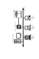
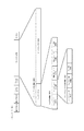
以下に図面を参照して本発明の実施例を詳細に説明する。図1は本発明の実施例のスキャナ/プリンタサーバーシステムのシステム構成図である。本実施例のシステムは、図1に示すように、上部にデジタルカラー画像読み取り部(以下「カラースキャナ」と称する)(100)(図2参照)と、デジタルカラー画像を印刷出力するデジタルカラー画像プリント部(以下に、カラープリンタと称する)(300)(図2参照)からなるデジタルカラー複写機(1000)と、ネットワーク(1)上に接続されているスキャナ/プリンタ(スキャナ/プリント)サーバー(200)と、ネットワーク上のファイルシステムをサポートするファイルサーバー(500)と、複数のクライアントユーザーのコンピュータ(400)により構成される。
【0008】
図2に、スキャナ/プリンタ機能を有する前述のカラーデジタル複写機(1000)の構成を示す。スキャナ部(100)では、スキャナコントローラ(101)が制御の中心となり、以下の制御を行っている。原稿台上の原稿をR・G・Bの各色ごとに、露光系コントロール(103)が、密着型CCDラインセンサにより色分解し、点順次のアナログ画像信号に変換する。このアナログ画像信号はA/D変換部で各色8bitのデジタル画像信号に変換され、輝度であるRGB各色がそれぞれ線順次信号として出力される。この画像信号(デジタル)は、画像処理部(102)で、R、G、Bの輝度レベルから、濃度であるC、M、Y、Bkの4色のトナー量に対応したレベルに変換される。そして、同時に画像処理部(102)で色補正演算され、合成、変倍、移動等の各種画像処理が行われる。
【0009】
電子写真方式のレーザビームプリンタであるカラープリンタ部(300)では、スキャナ部(100)より送られてきたC、M、Y、Bkの各デジタル画像信号が半導体レーザ部の点灯信号に変換され、レーザドライブ部(310)でレーザが制御され、そのレーザの点灯信号はデジタル画像信号のレベルに対応したパルス幅として出力され、レーザの点灯レベルは、256レベル(8bitに対応)となっている。この出力すべきデジタル画像信号に応じて、カラー画像を各CMYKのカラー別に制限し、それぞれ感光ドラム(315)に順次デジタル的なドット形式で露光・現像(314)し、用紙に複数転写(316)して、最後に定着(322)する。カラースキャナ部(100)とカラープリンタ部(300)は、カラースキャナ部(100)のコントロールにより、カラープリンタ部(300)を制御して、デジタルカラー複写機(1000)としても機能することが可能である。
【0010】
デジタルカラー複写機(1000)としても機能する際は、カラースキャナ部(100)の原稿台に、原稿画像をセットし、複写開始キーを押して、前述のプロセスに従ってカラースキャナ部からの画像の読み込み、画像処理、カラープリンタ部(300)での露光、現像、転写、定着のプロセスを経て画像が形成され、カラーコピーとして出力される。
【0011】
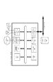
図3は、ネットワーク上のクライアントコンピュータ(400)の構造を示す。ホストコンピュータ(400)は、スキャナ/プリンタサーバー(200)/ファイルサーバー(500)とのネットワーク上のプロトコルを制御するためのネットワークコントローラ(420)と、クライアントコンピュータの中央制御のためのCPU(405)と、画像データの1時登録、各種データ記憶のためのハードディスク(451)と、それを制御するハードディスクコントローラ(450)と、メインメモリ(460)と、作業者からの指示入力手段としてのマウス(431)およびキーボード(441)と、レイアウト・編集・メニュー表示のためのカラーディスプレイ(412)と、ディスプレイメモリ(411)と、ディスプレイコントローラ(410)と、ディスプレイメモリ(411)上での画像レイアウト、編集を行う画像編集コントローラ(413)とから構成される。
【0012】
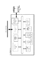
図4は、本発明によるスキャナ/プリンタサーバー(200)を示す。この装置は、大きく分けて、スキャナ/プリンタサーバー(200)全体を制御するメインコントローラ(210)と、ネットワーク上のプロトコル処理を制御するネットワークコントローラ(220)と、そのプロトコルにより抽出したパケットの内容の解析、画像データの分離など、サーバーとしての制御を行うネットワークサーバーコントローラ(221)と、分離された画像データ/コマンドデータに基づいて、カラー多値ラスタ画像データ及びその位置、属性情報を記憶/管理し、レイアウト等を行うラスタ画像記憶部(700)と、から構成される。
【0013】
また、インターフェイスとしては、デジタルカラー複写機(1000)との画像データや命令をやりとりするカラーデジタルインターフェイスコントローラ(790)と、サーバー管理者からの指示入力手段としてのマウス(244)やキーボード(245)と、レイアウト、編集、メニュー表示のためのカラーディスプレイ(242)と、ディスプレイメモリ(241)と、ディスプレイコントローラ(240)とがある。
【0014】
図5は、本発明によるファイルサーバー(500)を示す。このファイルサーバー装置は、大きく分けて、ネットワーク上のプロトコル処理を制御するネットワークコントローラ(520)と、そのプロトコルにより抽出したパケットの内容の解析、画像データの分離など、ファイルサーバー(500)全体としての制御を行うファイルサーバーメインコントローラ(510)と、単体もしくは複数のハードディスクを制御するハードディスクコントローラ(530)と、それに接続されるハードディスク(531)と、ハードディスク上に登録されたキューイングファイルデータを管理/制御するキュー管理コントローラ(550)と、その管理情報についてのキューテーブルデータ(551)と、ファイルサーバー管理者からの指示入力手段としてのマウス(544)やキーボード(545)と、メニュー表示のためのカラーディスプレイ(542)、ディスプレイメモリ(541)及びディスプレイコントローラ(540)とから構成される。
【0015】
図6は、スキャナ/プリンタサーバー内のラスタ画像記憶部(700)(図4)の構成図である。このラスタ画像記憶部(700)は、ラスタ画像データの全体を制御するイメージメインコントローラ(710)を中心に、カラーラスタ画像データをラスタイメージメモリ(760)へ効率よく配置及び管理を行うメモリ管理コントローラ(720)と、その管理テーブル(770)と、既に登録された画像データもしくはスキャナからメモリ上に画像登録する際に、色に関する画像変換および拡大/縮小/変形編集を行う画像編集コントローラ(730)と、プリンタ部へ出力する際にレイアウト編集をリアルタイムで行うレイアウトコントローラ(750)とで構成されている。
【0016】
メモリ上の画像データを出力する際には、カラーデジタルインターフェイスコントローラ(790)を介して、カラープリンタ部(300)に画像データを転送し、カラープリント画像を得ることができる。また、カラースキャナ部(100)から画像データを入力し、カラーデジタルインターフェイスコントローラ(790)を介して、メモリ上に画像データを登録することができる。
【0017】
ラスタ画像記憶部(700)とスキャナ/プリンタサーバー(200)のメインバスとの画像データ及び命令は、特定のフォーマットに基づいたものになっており、バスコントローラ(740)を介してイメージメインコントローラ(710)とスキャナ/プリンタサーバー(200)のメインコントローラとがやり取りを行う構成をとる。
【0018】
このラスタ画像記憶部(700)は、画像データをファイル管理モードとページモードの2つのモードで管理することが可能となっている。プリンタ出力において、1つ目のファイル管理モードは、画像データを複数個記憶/管理する機能で、記憶された画像データは、スキャナ/プリンタサーバーのメインコントローラ(210)からの命令によって、登録されている複数の画像データのそれぞれのレイアウトを行い、カラーデジタルインターフェイスコントローラ(790)を介して、カラープリンタ部(300)に出力し、カラープリンタ画像を得るものである。その際に複数の画像データは、画像ファイルとして、それぞれ、ラスタイメージメモリ(760)に複数に分割して管理されており、メモリ上のスタートアドレスとその画像データ長、画像データの属性、画像データのレイアウト出力の位置情報などが位置/属性情報テーブル(770)に登録され、それをメモリ管理コントローラ(720)が管理することになる。
【0019】
そして、実際に出力される際に、その登録された画像データの色に関する画像変換を行う画像編集コントローラ(730)とレイアウト出力する際に拡大/縮小/変形編集を行うレイアウトコントローラ(750)とにより画像データは指定された位置と大きさになり、カラーデジタルインターフェイスコントローラ(790)を介して、カラープリンタ部(300)に出力される。そのため、オリジナルの画像データは常時メモリ上にあるため、レイアウト出力を変えて行うことも可能となっている。
【0020】
スキャナ入力において、ファイル管理モードは、プリント出力と同様にスキャナ入力画像データを複数個記憶管理することができる。このとき、プリント出力用の画像データとスキャナ入力の画像データを混在させることも可能となっている。このスキャナから入力された画像は、プリントの時と同様にラスタイメージメモリ(760)を複数に分割して管理しており、メモリ上のスタートアドレスと、その画像データ長、画像データの属性が位置/属性情報テーブル(770)に登録され、それをメモリ管理コントローラ(720)が管理することになる。
【0021】
実際に入力される際に、カラースキャナ部(100)から入力されたスキャナ入力画像データの色に関する画像変換を行う画像編集コントローラ(730)と、入力時の拡大/縮小/変形編集を行うレイアウトコントローラ(750)により指定された入力サイズになり、ラスタ画像メモリ上に登録される。
【0022】
もう1つのメモリ管理モードであるページモードにおいては、ラスタイメージメモリ(760)を一枚の用紙として扱い、メモリを幅(WIDTH)/高さ(HEIGHT)で管理し、複数の画像データは、それぞれ、メモリ上にレイアウトされる際に、画像編集コントローラ(730)により、拡大/縮小/変形、及び画像データの色に関する画像変換が施されて、指定された画像メモリ上のレイアウト位置にはめ込まれる。
【0023】
このようにレイアウトコントローラ(750)により指定された位置と大きさになり、カラーデジタルインターフェイスコントローラ(790)を介して、カラープリンタ部(300)に出力されるか、もしくは、カラースキャナ部(100)から指定された大きさで画像データが、画像メモリ上に登録される。
【0024】
クライアントコンピュータ(400)/ファイルサーバー(500)/スキャナプリンタサーバー(200)のネットワーク上では、おのおの通信を行うために、図9に示すようなパケットと呼ばれるデータの列の集まりの1つのブロックを使用して、相互にパケットのやり取りを行うことになる。パケットの構造は、先頭に送信先のネットワークアドレス、次に送り元のネットワークアドレスをセットして、そのパケットのフレームサイズの情報の後に、実際のパケットデータ続き、最後にデータ転送の信頼性をあげるためにテーラーと呼ばれるCRC等のエラーチェックが付けられている。このパケットデータ部(10002)に関しては、任意のデータを入れることが可能だが、本実施例では、図9、図10のようにヘッダ部(10003)とデータブロック部(10100)に分かれる。
【0025】
パケツトデータ部(10002)のヘッダ部(10003)は、図9に示すように、まず先頭にヘッダ情報であることを示すヘッダコードが入り、次にこのパケットデータがどんな機能を持つかを示すファンクションコード部(10020)、複数のパケットにより1つのデータを構成する場合の連続No.(ナンバー)を示すパケットID(10030)、そのトータルのパケット数を示すトータルパケットID(10031)、そして、実際のデータが入るデータブロック部(10100)のデータの長さを示すデータ長(10032)により構成される。また、ファンクションコード部(10020)は、スキャナ/プリンタサーバーのタイプを示すファンクションID(10021)とサーバーに対してのジョブのタイプを示すジョブタイプID(10022)、実行されるジョブを識別するジョブ(10023)より構成される。
【0026】
次にパケットデータ部(10002)のデータブロック部(10100)は、図10に示すように、ヘッダ部のファンクションコード部のジョブタイプID(10022)の内容により、コマンドブロック(10005)、ステータスブロック(10006)、画像データブロック(10007)、画像情報ブロック(10008)に分けられる。以下、上記構成のスキャナ/プリンタサーバーシステムにおける本発明のファイルサーバータイプモード時のダイレクトコネクトプリントとダイレクトコネクトスキャンの動作の概略を図18及び図19と図20及び図21を参照して説明する。
【0027】
なお、ダイレクトインタイプモードが設定されている場合には、ファイルサーバー(500)を介さずにダイレクトにクライアントコンピュータ(ホスト)がS/Pサーバー(200)とコマンドやデータ等をやり取りしてデジタルカラー複写機1000でのプリント動作やスキャン動作を実行させる。
【0028】
この、ファイルサーバータイプモードとダイレクトインタイプモードは、クライアントコンピュータ(ホスト)側或いは、S/Pサーバー側で設定されるが、ネットワーク上でのモード設定の為特定のユーザーが設定すべきである。
【0029】
図1に示すスキャナ/プリントサーバーシステムにおけるファイルサーバータイプモード時の通常プリントは、ファイルサーバー(500)にコマンド登録してコマンド受理を受信後、ファイルサーバー(500)との間でデーター受信のやり取りを行い、ファイルサーバー(500)にスプールされたデータをS/Pサーバー(200)がデジタルカラー複写機1000でプリントさせる。
【0030】
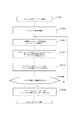
一方、図18及び図19に示す様なダイレクトコネクトプリントの場合は、コマンド受理受信後、直接S/Pサーバー(200)に対してデータ送信処理を行い、デジタルカラー複写機1000でプリントさせる。
そして、データ転送終了後、クローズコマンドを発行してダイレクト用のソケットをクローズしてジョブを終了する。S/Pサーバー(200)側は、クローズコマンドを受理して、かつデジタルカラー複写機1000のプリント動作が完全に終了した場合、ダイレクト用ソケットをクローズし、ファイルサーバー(500)に対してジョブ終了メッセージを発行する。
【0031】
また、図1に示すスキャナ/プリントサーバーシステムにおけるファイルサーバータイプモード時の通常スキャンは、ファイルサーバー(500)にコマンド登録してコマンド受理を受信後、ファイルサーバー(500)との間でデータ受信のやり取りを行い、デジタルカラー複写機1000でスキャンしたデータ等をファイルサーバー(500)にスプールした後、クライアントコンピュータ(ホスト)400に転送される。
【0032】
一方、図20及び図21に示す様なダイレクトコネクトスキャンの場合は、コマンド受理受信後、直接S/Pサーバー(200)に対してデータ受信処理を行い、デジタルカラー複写機1000でスキャンさせる。
そして、データ転送終了後、クローズコマンドを発行してダイレクト用のソケットをクローズしてジョブを終了する。S/Pサーバー(200)側は、クローズコマンドを受理して、かつデジタルカラー複写機1000のプリント動作が完全に終了した場合、ダイレクト用ソケットをクローズし、ファイルサーバー(500)に対してジョブ終了メッセージを発行する。
【0033】
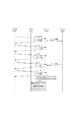
以下、ネットワーク上のスキャナに関して、スキャナ入力というリアルタイム性を要求されるダイレクトコネクトスキャンを例にあげ、その具体的な動作手順を図13から図16を参照して説明する。
【0034】
〈クライアントコンピュータ上のスキャン実行処理〉(図13)
クライアントコンピュータ(400)上で、スキャン入力用のソフトウェア(以下スキャナドライバという)がハードディスク(451)よりメインメモリ(460)上にロードされ〈STEP1〉、CPU(405)により実行される〈STEP2〉。ユーザーは、読み込むための原稿をデジタルカラー複写機の原稿台にセット〈STEP3〉し、マウス(431)、キーボード(441)を使用してディスプレイ(412)上で、スキャナ領域、カラーバランス設定、画像タイプ、原稿サイズの指定を行うことができる〈STEP5、6〉。
【0035】
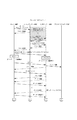
〈ファイルサーバーキューに対するステータス要求〉(図14)
ここで、スキャナドライバは、ネットワーク・コントローラ(420)に対して、ファイルサーバー(500)のネットワーク・コントローラ(520)と通信を行う。あらかじめクライアントコンピュータに登録してあるファイルサーバーのネットワークアドレス(453)を元に、ネットワーク・コントローラ(420)は、パケットベース(10001)の相手先アドレスをセットし、ヘッダ部のファンクションIDに機能を識別するIDとして一意的に決まっているカラースキャナ/プリンタ用のIDをセットし、実行形態がカラースキャナとプリンタに関するものであることを明示する。ジョブのIDは、まだジョブが確定していないので、0をセットし、ジョブのタイプIDとして、コマンドのデータブロツクであることを示す一意的に決まっているコマンドのIDをセットする。このときのデータブロック部は、ファイルサーバー側のキュー状態情報を入手するため、キューステータス要求のコマンドをセットする。
【0036】
クライアントコンピュータ(400)は、このパケットデータを、ネットワークコントローラ(420)を介して、ファイルサーバー(500)に転送する。ファイルサーバー側では、ファイルサーバーメインコントローラ(500)がそのパケットの内容をヘッダ部とデータブロック部とに分離し、データブロック部の内容がコマンドであることを解析し、そのコマンドにそった処理を行う。クライアント側からの要求は、ファイルサーバーのキューステータス要求のコマンドであるので、ファイルサーバーメインコントローラ(500)は、指定されたファンクションID(10021)にあたるスキャナ/プリンタのキュー情報があるかを、キュー管理コントローラに対して要求する〈STEP12〉。
【0037】
〈キューイングテーブルの参照〉(図14)
キューテーブルデータの構成は、複数のスキャナ/プリンタサーバーに対応できるように、キューイングエントリーテーブル内にそれぞれのスキャナ/プリンタサーバー用にキューイングテーブルを管理し、その各々のキューイングテーブル内には、クライアントからの要求されたプリント/スキャンのジョブが複数登録されている。キュー管理コントローラは、キューイングエントリーテーブルのなかに登録してあるキューイングテーブルの内容を参照し、各々キューイングテーブル内のキュータイプをチェックし、指定されたファンクションID(10021)に相当するものを探す。存在していた場合、そのキューイングテーブルデータから、全体のステータス情報を作成する。もし、複数の対象があった場合、複数分の全体のステータス情報を作成する。
【0038】
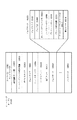
図8、図7に示すように、全体ステータス情報のデータは、指定されたファンクションID(10021)に相当するキューで、登録キューID(10209)とそのキューの対象となるプリンタサーバーのサーバーID/ネットワークID(10301)と、そのキューテーブルに割り当てられたキューイングファイルデータの登録可能容量(10313)、現在登録されているトータルのキュー数(10306)、登録可能な最大キュー数(10312)、登録されているキュー毎のクライアントの優先レベル(10314)、ジョブを登録したクライアントのネットワークID(10315)、エラーコードで構成されている。
【0039】
全体ステータス情報のデータは、パケットデータのデータブロック部にセットされ、ヘッダ内のジョブタイプIDをステータスブロックのIDにして、ステータス要求を発行したクライアントコンピュータに返送する。対象となるキュー情報が存在しない場合、一意的に決まっている対象スキャナ/プリンタが見つからないエラーコードをパケットデータのデータブロック部にセットし、ステータス要求を発行したクライアントコンピュータに返送する。
【0040】
〈キューイングテーブルのチェック〉(図14)
クライアントコンピュータは、ファイルサーバーより返送されたパケットデータの内容を前述したファイルサーバーと同じ様に分割/解析し、現在有効なスキャナ/プリンタサーバーにあたる登録キューIDを入手する〈STEP13〉。このとき、全体ステータス情報のデータから、現在進行中のキュー(10307)の優先レベル(10314)の値と、あらかじめ、クライアントコンピュータ上に設定されている優先レベルの値との比較を行う〈STEP15〉。この優先レベルは、ファイルサーバーに対して、キュー登録を行うか、もしくは、スキャン/プリントを実行する際に実行順の入れ換えを決めるための値で、各々クライアントコンピュータに対して1から10の優先順を付け、ファイルサーバーとスキャナ/プリンタサーバー側にクライアント優先テーブル(562/262)として登録されている。
【0041】
現在実行中のキューよりもクライアント側の優先レベルが低かった場合、クライアント側のスキャナドライバは、ユーザーにジョブが、直接スキャナ/プリンタサーバーに登録実行できない警告のメッセージを表示し〈STEP151〉、あらかじめ設定されていた一定時間後に前述した動作を繰り返し、ファイルサーバー上の実行ジョブの優先順位が、自分の優先順位より低くなるのを待つことになる〈STEP152〉。
【0042】
〈スキャナ/プリンタサーバーへの直接アクセス〉
ここで、本実施例の重要な処理である、直接スキャナ/プリンタサーバーに登録実行する前に前述したファイルサーバー(500)側の全体ステータス情報を入手し、その結果、現在実行中のキューよりもクライアント側の優先レベルが高かった場合の処理を述べる。
【0043】
〈スキャナ/プリンタサーバーへのスキャナ割り込み〉(図14)
クライアントコンピュータ(400)は、ファイルサーバー(500)より返送されたパケットデータの全体ステータス情報から、対象とするスキャナ/プリンタサーバーのネットワークID(10I/10301)をキューイングテーブル(10300)から割り込む。クライアントコンピュータは、スキャナ/プリンタサーバー(200)に対してパケットベースのデータブロック部に割り込み要求コマンドをセットし、前述した手順で転送する。
【0044】
この割り込み要求コマンドのパラメータとしては、前述したようにクライアントコンピュータのハードディスク上にあらかじめ登録してあるジョブ優先レベル(452)の値がセットされる〈STEP16〉。クライアントコンピュータは、スキャナ/プリンタサーバーに対して、割り込み要求コマンドを一定間隔毎に発送し、ある一定回数繰り返し、接続回答がない場合〈STEP17〉、スキャナドライバは、ユーザーにジョブが実行できない警告メッセージを表示し〈STEP172〉、あらかじめ設定されていた一定時間後に前述したようにファイルサーバー側に全体ステータス要求コマンドを発行する動作を繰り返し〈STEP171〉、ファイルサーバー上に空きができるのを持つことになる。
【0045】
スキャナ/プリンタサーバーは、この間に、現在実行中のジョブの画像データをファイルサーバーより受け取り、ラスタ画像データ部に順次登録する手順を実行しているが、一定間隔毎に他のクライアントからスキャナ要求がスキャナ/プリンタサーバーに直接送られていないかをネットワークサーバーコントローラ(221)がチェックする〈STEP18〉。
【0046】
〈クライアントの割り込みレベルチェック〉(図14、図15)
先のクライアント側からの割り込み要求コマンドのパケットを受け取ったスキャナ/プリンタサーバー(200)〈STEP181〉は、まず、クライアント優先レベルテーブル(262)から、割り込み要求のあった優先レベルと現在実行中のクライアントジョブの優先順位と比較する〈STEP19〉。現在実行中のジョブの優先順位が高かった場合〈STEP20〉、現在実行中のジョブの方が優先順位が高いことを示すエラーコードをパケットベースにセットし、ステータス情報としてクライアント側に返送する<STEP201>。
【0047】
クライアント側のスキャナドライバは、スキャナ/プリンタサーバー(200)からのステータス情報が、エラーであったことから、スキャナ/プリンタサーバーへのダイレクト(直接)接続ができなかったことを示すメッセージをユーザーに知らせる〈STEP202〉。ユーザーが確認後、ホスト上で設定された一定時間後に再度ファイルサーバーにアクセスし、同様の手順を繰り返す〈STEP203〉。割り込み要求のジョブの優先順位のほうが高かった場合、一意的に決められている割り込み用のジョブIDをステータスパケット内にセットし、前述したように、クライアント側に返送する。
【0048】
〈ジョブ中断コマンドの発行〉(図15)
スキャナ/プリンタサーバー(200)は、現在実行中のジョブを中断するためにファイルサーバー(500)に対して、ジョブ中断コマンドを発行する。このジョブ中断コマンドのパラメータは、スキャナ/プリンタサーバー上で実行していた対象となるジョブのジョブIDがセットされる〈STEP21〉。
【0049】
〈ジョブのリセット〉(図15)
ファイルサーバー(500)は、このコマンドパケット内から得られたジョブIDから対象となるキューテーブルを検出し、そのキューステータスを一意的に決められているインターラプト割り込み実行中の意味を持つ値に変更する〈STEP22〉。これにより、このジョブを実行していた他のクライアント側は、モニタリングの方法により、実行ジョブに割り込みが入ったことがキューステータス(10304)から分かる。
【0050】
〈スキャナ/プリンタサーバーにダイレクトスキャナ登録/画像データ転送〉(図15)
クライアントコンピュータ(400)のスキャナドライバは、スキャナ/プリンタサーバー(200)より返送されたステータスのパケットより、割り込みが認められたかをチェックし割り込みができた場合、ユーザーに対象となるデジタルカラー複写機のスキャナ部に読み込むための原稿のセットを確認するようにメッセージを出す。これにより、ユーザーは原稿を確認後、スキャナドライバに対して、原稿の用紙サイズと、割り込む際の画像データのタイプ(RGB、グレースケール、2値ビットマップ)、読み込む解像度、カラーバランスと確認の指示を出す〈STEP23〉。
【0051】
ここで、スキャナドライバは、パケットベース(10001)のジョブ(10023)を、先にスキャナ/プリンタサーバーより入手したステータスパケット内にセットされていた割り込み用ジョブIDと同じ値をセットし、ジョブタイプID(10022)としてコマンドタイプをセットする。このとき、データブロツク部(10100)は、スキャナ実行コマンドをセットし〈STEP23〉、そのコマンド部(10005)に、先にスキャナドライバがユーザーより指示されたスキャニングする原稿サイズ情報(幅、高さ)パラメータと、カラーバランス情報、解像情報と原稿サイズを元に算出した画像データの画像サイズ(幅、高さ)、画像データのタイプ(RGB、グレースケール、2値ビットマップ)のパラメータをセットする。このスキャナ実行コマンドのパケットは、前述したパケット転送と同様にネットワークコントローラにより、スキャナ/プリンタサーバー(200)側に転送される〈STEP231〉。
【0052】
〈スキャナ/プリンタサーバーへのスキャナ入力〉(図16)
スキャナ/プリンタサーバー(200)は、クライアントコンピュータ(400)からのスキャナ入力コマンドパケット(10005)を受信し、メインコントローラ(210)は前述したファイル管理モードで動作するように、ラスタイメージコントローラ(710)をセットアップする。これにより、イメージコントローラは、スキャニングした画像をラスタイメージメモリ(760)に登録するため、メモリ管理コントローラに対して登録する際の画像ファイルIDを任意のものにセットアップする。このIDをメモリ管理コントローラは、管理/識別用に使用する〈STEP60〉。
【0053】
スキャナ/プリンタサーバーのメインコントローラは、先のスキャナ入力コマンドにより入手した原稿サイズ情報/カラーバランス/画像サイズ/画像データのタイプのパラメータをレイアウトコントローラにセットし、カラーデジタル複写機のカラースキャナ部に対して、カラーデジタルインターフェイスコントローラ(790)を介してスキャナ入力のトリガをかける。これにより、ユーザーがセットした、原稿をRGB画像データとして入手し、その際に、レイアウトコントローラが、上記のユーザーの指定したパラメータに基づいた変換をリアルタイムで行い、画像データはラスタイメージメモリ(760)に転送され、先に決定された画像ファイルIDに対応する位置属性テーブル(770)に登録し、管理される〈STEP61〉。
【0054】
〈スキャナ入力中/完了等のステータス情報設定〉(図17)
スキャナ/プリンタサーバーが実行している割り込みのステータスは、随時、クライアントからモニタすることが可能となっている〈STEP640〉。スキャンが介しされた時点で、メインコントローラ(210)は、一定間隔ごとにスキャンの状況をラスタ画像記憶部(700)に問い合わせ、それにより、スキャンに関するエラー状況を確認し、その情報をメインメモリ(210)に保持する〈STEP642〉。このモニタ情報として、現在入力済みの面積の割合と、クライアントから指定されたスキャナ入力のエリア情報として、入力範囲の左上x、y座標と、そのサイズの幅、高さのピクセル数、入力処理の画像タイプ(RGB、グレースケール、2値ビットマップ)、入力エラーが発生した場合はそのエラーコード、正常にスキャナ入力が終了したことを示す終了フラグをメインメモリ上に登録する。
【0055】
〈クライアントのステータス情報モニタリング〉
クライアントコンピュータ(400)は、スキャン実行パケットを発行し、コマンドパケットを全て発行した後は、スキャナ/プリンタサーバー側の割り込み処理状況をモニタすることになる。クライアントコンピュータ(400)のスキャナドライバは、ネットワークコントローラ(420)を介して、ジョブステータス要求コマンドのコマンドパケットを発行する〈STEP642〉。このコマンドパケットは、パラメータとして、スキャナ入力の割り込み処理を示す、スキャナ/プリンタサーバーから指定されたジョブIDをセットし、スキャナ/プリンタサーバーに前述した手順により発行する。
【0056】
このジョブステータス要求コマンドをスキャナ/プリンタサーバーが受け取ると、先にメインメモリ上に登録されたモニタ情報を、ステータスパケットとして、クライアント側に返送する。この返送されたモニタ情報は、クライアントコンピュータ(400)のスキャナドライバが、スキャナ/プリンタサーバーより得られたステータス情報として、現在のスキャナ入力がどの割合まで進んでいるかその実行プロセスをディスプレイコントローラを介してディスプレイに表示する。また、エラーが発生した場合の判断もこのモニタ情報により判断される〈STEP644〉。
【0057】
スキャナドライバは、ある一定間隔ごとに、このモニタ情報を、ジョブステータス要求コマンドのパケットにより、スキャナ/プリンタサーバー側から入手する。クライアント側は、このモニタ情報の終了フラグにより、スキャナ入力完了かどうか知ることが可能となっている〈STEP645〉。スキャナドライバは、スキャナ入力が終了したことをユーザーにディスプレイを介して表示し、これから入力した画像データをクライアント側に転送するモードに入ることを表示する〈STEP646〉。
【0058】
〈スキャナ/プリンタサーバーの画像転送〉(図16)
クライアントコンピュータ(400)のスキャナドライバは、スキャナ入力処理が終了したことを、上記モニタ情報により判断し、画像データGETコマンド転送を前述した手順によりスキャナ/プリンタサーバーに発行する〈STEP65〉。このコマンドにより、スキャナ/プリンタサーバー(200)は、このスキャナより読み込んだ画像データを、クライアントに転送するため、この画像データサイズ分に当たる画像データブロックの全体パケット数を、ヘッダ(10020)のトータルパケットID(10031)にセットし、スキャナ読み込みされた画像を管理しているラスタイメージメモリ(760)から、画像データブロックに順次、連続パケットIDを付けて一連の画像データパケットとして転送を行う。これらの画像データパケットは、前述したパケット転送と同様に順次クライアント側に転送される〈STEP66〉。
【0059】
〈中断ジョブ再開〉(図16)
スキャナ/プリンタサーバーは、これにより割り込み入力処理が全て完了したので、ファイルサーバーに対して、先に中断したジョブを再実行処理を行う。〈STEP68〉。
【0060】
〈スキャナドライバの画像入手〉
スキャナ/プリンタサーバーより、送られてきたスキャナ入力画像データは、ホストコンピュータのネットワークコントローラを介して、スキャナドライバに転送され、画像データパケットから画像データを取り出す処理が行われる。この画像データは一旦ホストコンピュータ上のハードディスク(451)に蓄えられる。スキャナドライバは、この画像データをユーザーからの指示に基づいて、指定された画像ファイルフォーマットに再変換し、ハードディスク上に登録する〈STEP69〉。
【0061】
【発明の効果】
本発明によれば、サーバを介さずに、直接データ源からデータ入出力制御装置へのアクセスが可能となる。
【0062】
また画像入力状況をファイルサーバーを介さずに、直接、スキャナ/プリンタサーバーとクライアントの間で、モニタすることが可能となる。
【0063】
また、画像を読み込むというリアルタイム性を要求される機能を、効率よくモニタすることが可能となる。
【図面の簡単な説明】
【図1】実施例のネットワークシステム構成図である。
【図2】実施例のデジタルカラー複写機の構成図である。
【図3】実施例のクライアントコンピュータの構成図である。
【図4】実施例のスキャナ/プリンタサーバーの構成図である。
【図5】実施例のファイルサーバーの構成図である。
【図6】実施例のラスタ画像記憶部の構成図である。
【図7】実施例のキューイングエントリーテーブルの構成図である。
【図8】実施例のキューイングテーブルの図である。
【図9】実施例のネットワークパケットの全体/ヘッダ部の構成図である。
【図10】実施例のネットワークパケットのデータブロック部の構成図である。
【図11】実施例の連続ネットワークパケット構成図である。
【図12】実施例のキューイングファイルの構成図である。
【図13】実施例のサーバーシステムのフローチャートである。
【図14】実施例のサーバーシステムのフローチャートである。
【図15】実施例のサーバーシステムのフローチャートである。
【図16】実施例のサーバーシステムのフローチャートである。
【図17】実施例のサーバーシステムのフローチャートである。
【図18】実施例のダイレクトコネクトプリントの概略的なフローチャートである。
【図19】実施例のダイレクトコネクトプリントの概略的なフローチャートである。
【図20】実施例のダイレクトコネクトスキャンの概略的なフローチャートである。
【図21】実施例のダイレクトコネクトスキャンの概略的なフローチャートである。[0001]
BACKGROUND OF THE INVENTION
The present invention relates to a data input / output control apparatus, a data input / output control method, and a scanner / printer server system in a network system that allow a plurality of client users to share a scanner function or a print function on a network. .
[0002]
[Prior art]
In recent years, a plurality of computers are connected to a network to share data and share printer resources. Among these functions, a new scanner server function that allows a plurality of users to share a single scanner, which is different from the printer server, has been emphasized.
[0003]
[Problems to be solved by the invention]
The present invention, unlike a printer server, is a network that can answer a request from a client user as to how to effectively use a function of a scanner input on a network that requires real-time scanning, on the network. An object of the present invention is to provide a data input / output control device, a data input / output control method, and a scanner / printer server system in a system.
[0004]
[Means for Solving the Problems]
In order to achieve the above object, a data input / output control device of the present invention is a data input / output control device in a system in which a data source, a server, and a data input / output control device are connected on a network. Receiving means for receiving a direct command for requesting data communication between the data source and the data input / output control device without going through the server, and receiving the data during data communication through the server When the direct command is received by the means, the judgment means for judging whether or not the direct command from the data source can be accepted, and the judgment means for judging that the direct command can be accepted Between the data source and the data input / output controller without going through the server. To data communication, and having a control means for transmitting an interrupt command to the server. The data input / output control method of the present invention is a data input / output control method executed by a data input / output control device in a system in which a data source, a server, and a data input / output control device are connected on a network. A direct command for requesting data communication between the data source and the data input / output control device without passing through the server is received from the data source, and the direct command is received during data communication through the server. Is received, it is determined whether or not the direct command can be received from the data source, and when it is determined that the direct command can be received in the determination process, the server does not pass through the server. In order to communicate data between the data source and the data input / output controller, an interrupt command is And transmits the serial server.
[0005]
In order to achieve the above object, a data input / output control device according to the present invention is a data input / output control device in a system in which a data source, a server, and a data input / output control device are connected on a network. A receiving unit that receives from the data source a direct command for requesting data communication between the data source and the data input / output control device that is not interposed, and the receiving unit receives the direct command during data communication with the server. When received, the determination means for determining whether or not the direct command from the data source can be received, and when the determination means determines that the direct command can be received, the data with the server And control means for interrupting communication. The data input / output control method of the present invention is a data input / output control method executed by a data input / output control device in a system in which a data source, a server, and a data input / output control device are connected on a network. A receiving step of receiving a direct command for requesting data communication between the data source and the data input / output control device not via a server from the data source; and the directing in the receiving step during data communication with the server. A determination step for determining whether or not the direct command from the data source can be received when a command is received; and when determining that the direct command can be received in the determination step; Control step of interrupting the data communication of
In order to achieve the above object, a data input / output control device of the present invention is a data input / output control device in a system in which a data source, a server, and a data input / output control device are connected on a network. Receiving means for receiving a direct command for requesting data communication between the data source and the data input / output control device without going through the server, and the receiving during execution of a job through the server When the direct command is received by the means, the judgment means for judging whether or not the direct command from the data source can be accepted, and the judgment means for judging that the direct command can be accepted Between the data source and the data input / output controller without going through the server. To data communication, characterized by having a interrupting control means jobs through the running server. The data input / output control method of the present invention is a data input / output control method executed by a data input / output control device in a system in which a data source, a server, and a data input / output control device are connected on a network. A receiving step of receiving a direct command requesting data communication between the data source and the data input / output control device without going through the server from the data source; and during execution of a job through the server When the direct command is received in the receiving step, it is determined whether or not the direct command from the data source can be received, and it is determined that the direct command can be received in the determining step. The data source and the data without going through the server. To data communication with the input-output control unit, and having an interrupting control step jobs via the running server.
[0007]
DETAILED DESCRIPTION OF THE INVENTION
Embodiments of the present invention will be described below in detail with reference to the drawings. FIG. 1 is a system configuration diagram of a scanner / printer server system according to an embodiment of the present invention. As shown in FIG. 1, the system of this embodiment includes a digital color image reading unit (hereinafter referred to as “color scanner”) (100) (see FIG. 2) on the top, and a digital color image for printing out a digital color image. A digital color copying machine (1000) comprising a printing unit (hereinafter referred to as a color printer) (300) (see FIG. 2), and a scanner / printer (scanner / print) server (on the network (1)) 200), a file server (500) that supports a file system on the network, and a plurality of client user computers (400).
[0008]
FIG. 2 shows the configuration of the color digital copying machine (1000) having the scanner / printer function. In the scanner unit (100), the scanner controller (101) is the center of control and performs the following control. The exposure system control (103) separates the original on the original table for each of R, G, and B colors by the contact CCD line sensor and converts it into a dot sequential analog image signal. This analog image signal is converted into an 8-bit digital image signal of each color by an A / D converter, and each RGB color as luminance is output as a line sequential signal. The image signal (digital) is converted by the image processing unit (102) from the luminance levels of R, G, and B to levels corresponding to the toner amounts of the four colors C, M, Y, and Bk. . At the same time, a color correction calculation is performed by the image processing unit (102), and various image processing such as composition, scaling, and movement is performed.
[0009]
In the color printer unit (300), which is an electrophotographic laser beam printer, each digital image signal of C, M, Y, Bk sent from the scanner unit (100) is converted into a lighting signal of the semiconductor laser unit, The laser is controlled by the laser drive unit (310), the laser lighting signal is output as a pulse width corresponding to the level of the digital image signal, and the laser lighting level is 256 levels (corresponding to 8 bits). In accordance with the digital image signal to be output, the color image is limited for each CMYK color, exposed and developed (314) in a digital dot format on the photosensitive drum (315), and transferred onto a sheet (316). ) And finally fixing (322). The color scanner unit (100) and the color printer unit (300) can also function as a digital color copying machine (1000) by controlling the color printer unit (300) under the control of the color scanner unit (100). It is.
[0010]
When functioning as a digital color copying machine (1000), an original image is set on an original table of the color scanner unit (100), a copy start key is pressed, and an image is read from the color scanner unit according to the above-described process. An image is formed through image processing, exposure, development, transfer, and fixing processes in the color printer unit (300), and is output as a color copy.
[0011]
FIG. 3 shows the structure of the client computer (400) on the network. The host computer (400) includes a network controller (420) for controlling a protocol on the network with the scanner / printer server (200) / file server (500), and a CPU (405) for central control of the client computer. A hard disk (451) for temporarily registering image data and storing various data, a hard disk controller (450) for controlling it, a main memory (460), and a mouse ( 431) and a keyboard (441), a color display (412) for layout / editing / menu display, a display memory (411), a display controller (410), and an image layout on the display memory (411), Edit Image editing constructed from a controller (413) to perform.
[0012]
FIG. 4 shows a scanner / printer server (200) according to the present invention. This apparatus is roughly divided into a main controller (210) that controls the entire scanner / printer server (200), a network controller (220) that controls protocol processing on the network, and the contents of packets extracted by the protocol. A network server controller (221) that performs control as a server, such as analysis and image data separation, and stores / manages color multi-value raster image data and its position and attribute information based on the separated image data / command data And a raster image storage unit (700) for performing layout and the like.
[0013]
As an interface, a color digital interface controller (790) for exchanging image data and commands with the digital color copying machine (1000), a mouse (244) and a keyboard (245) as instruction input means from the server administrator. A color display (242) for layout, editing, and menu display, a display memory (241), and a display controller (240).
[0014]
FIG. 5 shows a file server (500) according to the present invention. This file server apparatus is roughly divided into a network controller (520) that controls protocol processing on the network, and analysis of the contents of packets extracted by the protocol, separation of image data, and the like as the entire file server (500). A file server main controller (510) for controlling, a hard disk controller (530) for controlling a single hard disk or a plurality of hard disks, a hard disk (531) connected thereto, and managing queuing file data registered on the hard disk A queue management controller (550) to be controlled, queue table data (551) for the management information, a mouse (544) and a keyboard (545) as instruction input means from the file server administrator, New display color display for (542), configured from a display memory (541) and the display controller (540).
[0015]
FIG. 6 is a configuration diagram of the raster image storage unit (700) (FIG. 4) in the scanner / printer server. The raster image storage unit (700) is a memory management controller that efficiently arranges and manages color raster image data in the raster image memory (760), centering on an image main controller (710) that controls the entire raster image data. (720), its management table (770), and image editing controller (730) that performs image conversion and enlargement / reduction / deformation editing related to colors when registering an image in the memory from already registered image data or a scanner And a layout controller (750) that performs layout editing in real time when output to the printer unit.
[0016]
When outputting the image data on the memory, the image data can be transferred to the color printer unit (300) via the color digital interface controller (790) to obtain a color print image. In addition, image data can be input from the color scanner unit (100) and registered in the memory via the color digital interface controller (790).
[0017]
The image data and commands of the raster image storage unit (700) and the main bus of the scanner / printer server (200) are based on a specific format, and the image main controller (via the bus controller (740)). 710) and the main controller of the scanner / printer server (200) communicate with each other.
[0018]
The raster image storage unit (700) can manage image data in two modes, a file management mode and a page mode. In the printer output, the first file management mode is a function for storing / managing a plurality of image data. The stored image data is registered by a command from the main controller (210) of the scanner / printer server. Each of the plurality of image data is laid out and output to the color printer unit (300) via the color digital interface controller (790) to obtain a color printer image. At that time, the plurality of image data are managed as divided into a plurality of raster image memories (760) as image files, and the start address on the memory, its image data length, image data attributes, image data The position information of the layout output is registered in the position / attribute information table (770), and the memory management controller (720) manages it.
[0019]
An image editing controller (730) that performs image conversion relating to the color of the registered image data when actually output, and a layout controller (750) that performs enlargement / reduction / deformation editing when outputting the layout. The image data has the designated position and size, and is output to the color printer unit (300) via the color digital interface controller (790). Therefore, since the original image data is always on the memory, it is possible to change the layout output.
[0020]
In the scanner input, the file management mode can store and manage a plurality of scanner input image data in the same manner as the print output. At this time, it is possible to mix image data for print output and image data for scanner input. The image input from the scanner is managed by dividing the raster image memory (760) into a plurality of parts in the same manner as when printing, and the start address on the memory, the image data length, and the attribute of the image data are located. / Registered in the attribute information table (770) and managed by the memory management controller (720).
[0021]
An image editing controller (730) that performs image conversion on the color of the scanner input image data input from the color scanner unit (100) when actually input, and a layout controller that performs enlargement / reduction / deformation editing at the time of input The input size specified by (750) is set and registered in the raster image memory.
[0022]
In the page mode, which is another memory management mode, the raster image memory (760) is handled as one sheet, the memory is managed by width (WIDTH) / height (HEIGHT), and each of the plurality of image data is When the image is laid out on the memory, the image editing controller (730) performs enlargement / reduction / deformation and image conversion relating to the color of the image data, and fits the specified layout position on the image memory.
[0023]
Thus, the position and size specified by the layout controller (750) are output to the color printer unit (300) via the color digital interface controller (790), or the color scanner unit (100). The image data is registered in the image memory with the size specified from the above.
[0024]
On the network of the client computer (400) / file server (500) / scanner printer server (200), one block of a collection of data strings called packets as shown in FIG. 9 is used for each communication. Thus, packets are exchanged with each other. The packet structure is such that the destination network address and then the source network address are set at the beginning, the frame size information of the packet is followed by the actual packet data, and finally the reliability of the data transfer is raised. Therefore, error checking such as CRC called tailor is added. Arbitrary data can be entered in the packet data portion (10002), but in this embodiment, it is divided into a header portion (10003) and a data block portion (10100) as shown in FIGS.
[0025]
As shown in FIG. 9, the header part (10003) of the packet data part (10002) has a header code indicating header information at the beginning, and then a function code indicating what function the packet data has. Part (10020), a continuous No. in the case where one data is constituted by a plurality of packets. Packet ID (10030) indicating (number), total packet ID (10031) indicating the total number of packets, and data length (10032) indicating the data length of the data block portion (10100) into which actual data is stored Consists of. The function code section (10020) includes a function ID (10021) indicating the type of the scanner / printer server, a job type ID (10022) indicating the type of job for the server, and a job ( 10023).
[0026]
Next, as shown in FIG. 10, the data block portion (10100) of the packet data portion (10002) has a command block (10005) and a status block ( 10006), an image data block (10007), and an image information block (10008). An outline of operations of direct connect printing and direct connect scan in the file server type mode of the present invention in the scanner / printer server system having the above-described configuration will be described below with reference to FIGS. 18, 19, 20 and 21. FIG.
[0027]
When the direct-in type mode is set, the client computer (host) directly exchanges commands and data with the S / P server (200) without going through the file server (500), and digital color A printing operation and a scanning operation in the copying machine 1000 are executed.
[0028]
The file server type mode and the direct-in type mode are set on the client computer (host) side or the S / P server side, but should be set by a specific user for mode setting on the network.
[0029]
In normal printing in the file server type mode in the scanner / print server system shown in FIG. 1, after receiving a command acceptance and registering a command in the file server (500), exchange of data reception with the file server (500) is performed. The S / P server (200) causes the digital color copying machine 1000 to print the data spooled in the file server (500).
[0030]
On the other hand, in the case of direct connect printing as shown in FIGS. 18 and 19, after receiving a command, data is directly transmitted to the S / P server (200) and printed by the digital color copier 1000.
After the data transfer is completed, a close command is issued to close the direct socket and the job is terminated. When the S / P server (200) receives the close command and the printing operation of the digital color copying machine 1000 is completed, the direct socket is closed and the job to the file server (500) is completed. Issue a message.
[0031]
In the normal scan in the file server type mode in the scanner / print server system shown in FIG. 1, a command is registered in the file server (500) and command reception is received, and then data is received from the file server (500). After exchanging data, the data scanned by the digital color copying machine 1000 is spooled to the file server (500) and then transferred to the client computer (host) 400.
[0032]
On the other hand, in the case of the direct connect scan as shown in FIG. 20 and FIG. 21, after receiving the command, the data reception process is directly performed on the S / P server (200), and the digital color copying machine 1000 scans.
After the data transfer is completed, a close command is issued to close the direct socket and the job is terminated. When the S / P server (200) accepts the close command and the printing operation of the digital color copying machine 1000 is completely completed, the S / P server (200) closes the direct socket and ends the job to the file server (500). Issue a message.
[0033]
In the following, with respect to the scanner on the network, a direct connect scan that requires real-time scanner input will be taken as an example, and the specific operation procedure will be described with reference to FIGS.
[0034]
<Scan Execution Processing on Client Computer> (FIG. 13)
On the client computer (400), scan input software (hereinafter referred to as a scanner driver) is loaded from the hard disk (451) onto the main memory (460) <STEP1> and executed by the CPU (405) <STEP2>. The user sets a document to be read on the platen of the digital color copying machine <
[0035]
<Status request for file server queue> (FIG. 14)
Here, the scanner driver communicates with the network controller (520) of the file server (500) with respect to the network controller (420). Based on the network address (453) of the file server registered in advance in the client computer, the network controller (420) sets the destination address of the packet base (10001) and identifies the function in the function ID of the header part. The ID for the color scanner / printer uniquely determined as the ID to be set is set, and it is clearly indicated that the execution form relates to the color scanner and the printer. Since the job ID has not yet been determined, 0 is set, and the ID of the command that is uniquely determined to indicate that it is a data block of the command is set as the job type ID. The data block unit at this time sets a queue status request command in order to obtain queue status information on the file server side.
[0036]
The client computer (400) transfers this packet data to the file server (500) via the network controller (420). On the file server side, the file server main controller (500) separates the contents of the packet into a header part and a data block part, analyzes that the data block part is a command, and performs processing according to the command. Do. Since the request from the client side is a command for requesting the queue status of the file server, the file server main controller (500) determines whether there is scanner / printer queue information corresponding to the specified function ID (10021). Request to the controller <STEP 12>.
[0037]
<Referencing the queuing table> (FIG. 14)
The configuration of the queue table data is to manage a queue table for each scanner / printer server in the queue entry table so that the scanner / printer server can support a plurality of scanner / printer servers. A plurality of print / scan jobs requested from the client are registered. The queue management controller refers to the contents of the queuing table registered in the queuing entry table, checks the queue type in each queuing table, and finds the one corresponding to the specified function ID (10021). look for. If it exists, overall status information is created from the queuing table data. If there are multiple objects, create status information for multiple items.
[0038]
As shown in FIGS. 8 and 7, the data of the overall status information is a queue corresponding to the designated function ID (10021), and the registration queue ID (10209) and the server ID / ID of the printer server that is the target of the queue. Network ID (10301), queuing file data registration capacity (10313) assigned to the queue table, total number of queues currently registered (10306), maximum number of queues that can be registered (10312), registration The client priority level (10314) for each queue, the network ID (10315) of the client that registered the job, and an error code.
[0039]
The data of the entire status information is set in the data block portion of the packet data, and the job type ID in the header is set as the status block ID and returned to the client computer that issued the status request. If there is no target queue information, an error code for which a uniquely determined target scanner / printer cannot be found is set in the data block portion of the packet data, and returned to the client computer that issued the status request.
[0040]
<Checking the queuing table> (Fig. 14)
The client computer divides / analyzes the contents of the packet data returned from the file server in the same manner as the file server described above, and obtains a registration queue ID corresponding to the currently valid scanner / printer server <STEP 13>. At this time, the value of the priority level (10314) of the currently ongoing queue (10307) is compared with the value of the priority level set in advance on the client computer from the data of the overall status information <STEP 15> . This priority level is a value for deciding whether to perform queue registration with the file server or to change the execution order when executing scan / print, and each client computer has a priority order of 1 to 10. And registered as a client priority table (562/262) on the file server and the scanner / printer server side.
[0041]
If the client-side priority level is lower than the queue currently being executed, the client-side scanner driver displays a warning message indicating that the job cannot be registered directly to the scanner / printer server to the user <STEP 151> and set in advance. The above-described operation is repeated after a certain period of time, and the process waits for the priority of the execution job on the file server to become lower than its own priority (STEP 152).
[0042]
<Direct access to the scanner / printer server>
Here, the above-mentioned overall status information on the file server (500) side is obtained before executing registration directly to the scanner / printer server, which is an important process of the present embodiment. The processing when the priority level on the client side is high will be described.
[0043]
<Scanner interrupt to scanner / printer server> (FIG. 14)
The client computer (400) interrupts the network ID (10I / 10301) of the target scanner / printer server from the queuing table (10300) from the overall status information of the packet data returned from the file server (500). The client computer sets an interrupt request command in the packet-based data block unit to the scanner / printer server (200), and transfers it according to the procedure described above.
[0044]
As a parameter of this interrupt request command, the value of the job priority level (452) registered in advance on the hard disk of the client computer as described above is set <STEP 16>. The client computer sends an interrupt request command to the scanner / printer server at regular intervals, and repeats a certain number of times. If there is no connection response <STEP 17>, the scanner driver issues a warning message that the user cannot execute the job. It is displayed <STEP 172>, and the operation of issuing the entire status request command to the file server side is repeated after a predetermined time set in advance <STEP 171>, so that there is a free space on the file server.
[0045]
During this time, the scanner / printer server receives the image data of the job currently being executed from the file server and executes the procedure of sequentially registering it in the raster image data section. However, a scanner request is received from another client at regular intervals. The network server controller (221) checks whether it is sent directly to the scanner / printer server <STEP 18>.
[0046]
<Client interrupt level check> (FIGS. 14 and 15)
The scanner / printer server (200) <STEP 181>, which has received the interrupt request command packet from the previous client side, first, from the client priority level table (262), the priority level requested to be interrupted and the currently executing client. Compare with the job priority <STEP 19>. If the priority of the job currently being executed is higher <STEP 20>, an error code indicating that the job currently being executed has a higher priority is set in the packet base and returned to the client side as status information <STEP 201 >.
[0047]
The scanner driver on the client side notifies the user of a message indicating that the direct connection to the scanner / printer server could not be made because the status information from the scanner / printer server (200) was an error. <STEP 202>. After the user confirms, the file server is accessed again after a predetermined time set on the host, and the same procedure is repeated <STEP 203>. If the priority of the interrupt request job is higher, a uniquely determined interrupt job ID is set in the status packet and returned to the client side as described above.
[0048]
<Issuance of job interruption command> (FIG. 15)
The scanner / printer server (200) issues a job interruption command to the file server (500) in order to interrupt the job currently being executed. As the parameter of the job interruption command, the job ID of the target job executed on the scanner / printer server is set <STEP 21>.
[0049]
<Job reset> (Fig. 15)
The file server (500) detects the target queue table from the job ID obtained from this command packet, and changes the queue status to a value that is uniquely determined during interrupt interrupt execution. <STEP22>. As a result, the other client side executing this job can know from the queue status (10304) that the execution job has been interrupted by the monitoring method.
[0050]
<Direct Scanner Registration / Image Data Transfer to Scanner / Printer Server> (FIG. 15)
The scanner driver of the client computer (400) checks whether or not an interrupt is accepted from the status packet returned from the scanner / printer server (200). A message is displayed to confirm the set of documents to be read into the scanner unit. As a result, after confirming the document, the user instructs the scanner driver to determine the paper size of the document, the type of image data to be interrupted (RGB, grayscale, binary bitmap), resolution to be read, color balance, and confirmation. <STEP23>.
[0051]
Here, the scanner driver sets the same value as the interrupt job ID set in the status packet obtained from the scanner / printer server for the packet-based (10001) job (10023), and sets the job type ID. The command type is set as (10022). At this time, the data block unit (10100) sets a scanner execution command <STEP 23>, and in the command unit (10005), the document size information (width and height) to be scanned by the scanner driver previously designated by the user. Set parameters, color balance information, resolution information and image size (width, height) of image data calculated based on the document size, and image data type (RGB, grayscale, binary bitmap). . The packet of the scanner execution command is transferred to the scanner / printer server (200) side by the network controller in the same manner as the packet transfer described above <STEP 231>.
[0052]
<Scanner input to scanner / printer server> (FIG. 16)
The scanner / printer server (200) receives the scanner input command packet (10005) from the client computer (400), and the main controller (210) operates in the file management mode described above so that the raster image controller (710). Set up. As a result, the image controller registers the scanned image in the raster image memory (760), and sets up an arbitrary image file ID when registering with the memory management controller. The memory management controller uses this ID for management / identification <STEP 60>.
[0053]
The main controller of the scanner / printer server sets the document size information / color balance / image size / image data type parameters obtained by the previous scanner input command in the layout controller, and sends it to the color scanner section of the color digital copying machine. Then, the scanner input is triggered via the color digital interface controller (790). As a result, the original set by the user is obtained as RGB image data, and at that time, the layout controller performs conversion based on the parameters designated by the user in real time, and the image data is stored in the raster image memory (760). And is registered and managed in the position attribute table (770) corresponding to the previously determined image file ID <STEP 61>.
[0054]
<Status information setting for scanner input / completion, etc.> (FIG. 17)
The status of the interrupt being executed by the scanner / printer server can be monitored from the client at any time (STEP 640). When the scan is passed, the main controller (210) inquires of the raster image storage unit (700) about the scan status at regular intervals, thereby confirming the error status related to the scan and storing the information in the main memory ( 210) <STEP 642>. As the monitor information, the ratio of the currently input area, the scanner input area information designated by the client, the upper left x and y coordinates of the input range, the size width, the number of pixels in the height, the input processing An image type (RGB, gray scale, binary bitmap), an error code when an input error occurs, and an end flag indicating that the scanner input has ended normally are registered in the main memory.
[0055]
<Client status information monitoring>
The client computer (400) issues a scan execution packet and, after issuing all command packets, monitors the interrupt processing status on the scanner / printer server side. The scanner driver of the client computer (400) issues a command packet of a job status request command via the network controller (420) <STEP 642>. This command packet is set with a job ID designated by the scanner / printer server indicating the scanner input interrupt process as a parameter, and is issued to the scanner / printer server by the procedure described above.
[0056]
When the scanner / printer server receives this job status request command, the monitor information previously registered in the main memory is returned to the client side as a status packet. The returned monitor information is the status information obtained from the scanner / printer server by the scanner driver of the client computer (400) as to how much the current scanner input has progressed through the display controller. Show on the display. Further, the determination when an error occurs is also determined by this monitor information <STEP 644>.
[0057]
The scanner driver obtains this monitor information from the scanner / printer server side by a job status request command packet at regular intervals. The client side can know whether or not the scanner input is completed by using the monitor information end flag <STEP 645>. The scanner driver displays to the user through the display that the scanner input has been completed, and displays that it enters a mode for transferring the image data input from now on to the client side (STEP 646).
[0058]
<Image transfer of scanner / printer server> (FIG. 16)
The scanner driver of the client computer (400) determines that the scanner input process has been completed based on the monitor information, and issues an image data GET command transfer to the scanner / printer server according to the procedure described above (STEP 65). In response to this command, the scanner / printer server (200) transfers the image data read from the scanner to the client. Therefore, the total number of packets of the image data block corresponding to the image data size is calculated as the total packet of the header (10020). The raster image memory (760) which is set to ID (10031) and manages the image read by the scanner sequentially transfers image data blocks as sequential image data packets with sequential packet IDs. These image data packets are sequentially transferred to the client side similarly to the packet transfer described above <STEP 66>.
[0059]
<Resuming interrupted job> (FIG. 16)
The scanner / printer server completes the interrupt input processing in this way, and re-executes the previously interrupted job for the file server. <STEP68>.
[0060]
<Acquiring scanner driver images>
The scanner input image data sent from the scanner / printer server is transferred to the scanner driver via the network controller of the host computer, and processing for extracting the image data from the image data packet is performed. This image data is temporarily stored in the hard disk (451) on the host computer. The scanner driver reconverts the image data into the designated image file format based on an instruction from the user, and registers it on the hard disk <STEP 69>.
[0061]
【The invention's effect】
According to the present invention, it is possible to directly access a data input / output control device from a data source without using a server.
[0062]
In addition, the image input status can be directly monitored between the scanner / printer server and the client without using the file server.
[0063]
In addition, it is possible to efficiently monitor a function that requires real-time performance of reading an image.
[Brief description of the drawings]
FIG. 1 is a configuration diagram of a network system according to an embodiment.
FIG. 2 is a configuration diagram of a digital color copying machine according to an embodiment.
FIG. 3 is a configuration diagram of a client computer according to the embodiment.
FIG. 4 is a configuration diagram of a scanner / printer server according to the embodiment.
FIG. 5 is a configuration diagram of a file server according to the embodiment.
FIG. 6 is a configuration diagram of a raster image storage unit according to the embodiment.
FIG. 7 is a configuration diagram of a queuing entry table according to the embodiment.
FIG. 8 is a diagram of a queuing table of the embodiment.
FIG. 9 is a configuration diagram of an entire network packet / header portion of an embodiment;
FIG. 10 is a configuration diagram of a data block unit of a network packet according to the embodiment.
FIG. 11 is a configuration diagram of a continuous network packet according to the embodiment.
FIG. 12 is a configuration diagram of a queuing file according to the embodiment.
FIG. 13 is a flowchart of the server system according to the embodiment.
FIG. 14 is a flowchart of the server system according to the embodiment.
FIG. 15 is a flowchart of the server system according to the embodiment.
FIG. 16 is a flowchart of the server system according to the embodiment.
FIG. 17 is a flowchart of the server system according to the embodiment.
FIG. 18 is a schematic flowchart of direct connect printing according to an embodiment.
FIG. 19 is a schematic flowchart of direct connect printing according to the embodiment.
FIG. 20 is a schematic flowchart of direct connect scanning according to the embodiment.
FIG. 21 is a schematic flowchart of direct connect scanning according to the embodiment.
Claims (19)
前記データ源から、前記サーバを介することなく前記データ源と前記データ入出力制御装置との間でデータ通信することを要求するダイレクトコマンドを受信する受信手段と、
前記サーバを介してのデータ通信中に前記受信手段により前記ダイレクトコマンドが受信された場合、前記データ源からの前記ダイレクトコマンドを受けつけることができるか否かを判断する判断手段と、
前記判断手段で前記ダイレクトコマンドを受けつけることができると判断した場合に、前記サーバを介することなく前記データ源と前記データ入出力制御装置との間でデータ通信するために、中断コマンドを前記サーバに送信する制御手段とを有することを特徴とするデータ入出力制御装置。A data input / output control device in a system in which a data source, a server, and a data input / output control device are connected on a network,
Receiving means for receiving, from the data source, a direct command for requesting data communication between the data source and the data input / output control device without going through the server;
A determination means for determining whether or not the direct command from the data source can be received when the direct command is received by the receiving means during data communication via the server;
If the determination means determines that the direct command can be accepted, an interrupt command is sent to the server in order to perform data communication between the data source and the data input / output control device without going through the server. And a data input / output control device.
前記データ源から、前記サーバを介することなく前記データ源と前記データ入出力制御装置との間でデータ通信することを要求するダイレクトコマンドを受信し、
前記サーバを介してのデータ通信中に前記ダイレクトコマンドが受信された場合、前記データ源から前記ダイレクトコマンドを受けつけることができるか否かを判断し、
前記判断処理で前記ダイレクトコマンドを受けつけることができると判断した場合に、前記サーバを介することなく前記データ源と前記データ入出力制御装置との間でデータ通信するために、中断コマンドを前記サーバに送信することを特徴とするデータ入出力制御方法。A data input / output control method executed by a data input / output control device in a system in which a data source, a server, and a data input / output control device are connected on a network,
From the data source, receiving a direct command requesting data communication between the data source and the data input / output control device without going through the server,
If the direct command is received during data communication through the server, determine whether the direct command can be received from the data source;
If it is determined that the direct command can be accepted in the determination process, an interrupt command is sent to the server in order to perform data communication between the data source and the data input / output control device without going through the server. A data input / output control method comprising transmitting data.
前記サーバを介することがない前記データ源と前記データ入出力制御装置とのデータ通信を要求するダイレクトコマンドを前記データ源から受信する受信手段と、
前記サーバとのデータ通信中に前記受信手段により前記ダイレクトコマンドが受信されたとき、前記データ源からの前記ダイレクトコマンドを受けつけることができるか否かを判断する判断手段と、
前記判断手段で前記ダイレクトコマンドを受けつけることができると判断した場合、前記サーバとのデータ通信を中断する制御手段とを有することを特徴とするデータ入出力制御装置。A data input / output control device in a system in which a data source, a server, and a data input / output control device are connected on a network,
Receiving means for receiving, from the data source, a direct command for requesting data communication between the data source and the data input / output control device not via the server;
A determination means for determining whether or not the direct command from the data source can be received when the direct command is received by the receiving means during data communication with the server;
A data input / output control apparatus comprising: control means for interrupting data communication with the server when the determination means determines that the direct command can be received.
前記サーバを介することがない前記データ源と前記データ入出力制御装置とのデータ通信を要求するダイレクトコマンドを前記データ源から受信する受信ステップと、
前記サーバとのデータ通信中に前記受信ステップで前記ダイレクトコマンドが受信されたとき、前記データ源からの前記ダイレクトコマンドを受けつけることができるか否かを判断する判断ステップと、
前記判断ステップで前記ダイレクトコマンドを受けつけることができると判断した場合、前記サーバとのデータ通信を中断する制御ステップとを有することを特徴とするデータ入出力制御方法。A data input / output control method executed by a data input / output control device in a system in which a data source, a server, and a data input / output control device are connected on a network,
Receiving from the data source a direct command for requesting data communication between the data source and the data input / output control device not via the server;
A determination step of determining whether or not the direct command from the data source can be received when the direct command is received in the reception step during data communication with the server;
And a control step of interrupting data communication with the server when it is determined in the determining step that the direct command can be received.
前記データ源から、前記サーバを介することなく前記データ源と前記データ入出力制御装置との間でデータ通信することを要求するダイレクトコマンドを受信する受信手段と、
前記サーバを介したジョブの実行中に前記受信手段により前記ダイレクトコマンドが受信された場合、前記データ源からの前記ダイレクトコマンドを受けつけることができるか否かを判断する判断手段と、
前記判断手段で前記ダイレクトコマンドを受けつけることができると判断した場合に、前記サーバを介することなく前記データ源と前記データ入出力制御装置との間でデータ通信するために、実行中の前記サーバを介したジョブを中断する制御手段とを有することを特徴とするデータ入出力制御装置。A data input / output control device in a system in which a data source, a server, and a data input / output control device are connected on a network,
Receiving means for receiving, from the data source, a direct command for requesting data communication between the data source and the data input / output control device without going through the server;
A determination means for determining whether or not the direct command from the data source can be received when the direct command is received by the receiving means during execution of a job via the server;
When the determination means determines that the direct command can be accepted, the server being executed is connected to the data source and the data input / output control device without going through the server. And a data input / output control device comprising: a control means for interrupting the job via
前記データ源から、前記サーバを介することなく前記データ源と前記データ入出力制御装置との間でデータ通信することを要求するダイレクトコマンドを受信する受信ステップと、
前記サーバを介したジョブの実行中に前記受信ステップにより前記ダイレクトコマンドが受信された場合、前記データ源からの前記ダイレクトコマンドを受けつけることができるか否かを判断する判断ステップと、
前記判断ステップで前記ダイレクトコマンドを受けつけることができると判断した場合に、前記サーバを介することなく前記データ源と前記データ入出力制御装置との間でデータ通信するために、実行中の前記サーバを介したジョブを中断する制御ステップとを有することを特徴とするデータ入出力制御方法。A data input / output control method executed by a data input / output control device in a system in which a data source, a server, and a data input / output control device are connected on a network,
Receiving from the data source a direct command requesting data communication between the data source and the data input / output control device without going through the server;
A determination step of determining whether or not the direct command from the data source can be received when the direct command is received by the reception step during execution of a job via the server;
If it is determined in the determining step that the direct command can be received, the server being executed is communicated between the data source and the data input / output control device without going through the server. And a data input / output control method, comprising:
Priority Applications (2)
| Application Number | Priority Date | Filing Date | Title |
|---|---|---|---|
| JP33035895A JP3720439B2 (en) | 1995-01-06 | 1995-12-19 | Data input / output control apparatus and data input / output control method |
| US08/582,180 US5845076A (en) | 1995-01-06 | 1996-01-02 | Data input/output apparatus couped to a network for accepting direct commands from a data source after receiving request through the server |
Applications Claiming Priority (3)
| Application Number | Priority Date | Filing Date | Title |
|---|---|---|---|
| JP1650695 | 1995-01-06 | ||
| JP7-16506 | 1995-01-06 | ||
| JP33035895A JP3720439B2 (en) | 1995-01-06 | 1995-12-19 | Data input / output control apparatus and data input / output control method |
Publications (2)
| Publication Number | Publication Date |
|---|---|
| JPH08241182A JPH08241182A (en) | 1996-09-17 |
| JP3720439B2 true JP3720439B2 (en) | 2005-11-30 |
Family
ID=26352854
Family Applications (1)
| Application Number | Title | Priority Date | Filing Date |
|---|---|---|---|
| JP33035895A Expired - Fee Related JP3720439B2 (en) | 1995-01-06 | 1995-12-19 | Data input / output control apparatus and data input / output control method |
Country Status (2)
| Country | Link |
|---|---|
| US (1) | US5845076A (en) |
| JP (1) | JP3720439B2 (en) |
Families Citing this family (53)
| Publication number | Priority date | Publication date | Assignee | Title |
|---|---|---|---|---|
| US6768563B1 (en) * | 1995-02-24 | 2004-07-27 | Canon Kabushiki Kaisha | Image input system |
| US6529287B1 (en) * | 1996-01-31 | 2003-03-04 | Avision Inc. | Image processing system |
| JPH10124441A (en) * | 1996-10-18 | 1998-05-15 | Brother Ind Ltd | Multifunctional information processing system and information recording medium |
| JP3507307B2 (en) * | 1996-12-27 | 2004-03-15 | キヤノン株式会社 | Information processing apparatus, network print system, control method therefor, and storage medium storing program |
| JP3630943B2 (en) * | 1997-02-07 | 2005-03-23 | キヤノン株式会社 | Information processing apparatus, print control method, print control system, and storage medium storing print control program |
| US6675195B1 (en) * | 1997-06-11 | 2004-01-06 | Oracle International Corporation | Method and apparatus for reducing inefficiencies caused by sending multiple commands to a server |
| US6623527B1 (en) * | 1997-11-19 | 2003-09-23 | International Business Machines Corporation | Method for providing a document with a button for a network service |
| JP3787427B2 (en) * | 1997-11-28 | 2006-06-21 | キヤノン株式会社 | Data processing method and storage medium for printer server |
| JP4324993B2 (en) * | 1998-02-17 | 2009-09-02 | ソニー株式会社 | Data transfer method and apparatus |
| US6785022B1 (en) * | 1998-04-07 | 2004-08-31 | Canon Kabushiki Kaisha | Data communication method of apparatus connected to LAN |
| US6751648B2 (en) * | 1998-10-06 | 2004-06-15 | Canon Kabushiki Kaisha | System for sharing image input device on network |
| JP2000115445A (en) * | 1998-10-06 | 2000-04-21 | Canon Inc | Communication device, communication system, and storage medium |
| US6381029B1 (en) * | 1998-12-23 | 2002-04-30 | Etrauma, Llc | Systems and methods for remote viewing of patient images |
| US7266761B2 (en) * | 1999-06-15 | 2007-09-04 | Microsoft Corporation | Special API interface for interfacing an application with a TWAIN module, negotiating and presenting a user interface for inserting an image into a document |
| US6606374B1 (en) | 1999-06-17 | 2003-08-12 | Convergys Customer Management Group, Inc. | System and method for recording and playing audio descriptions |
| TW424384B (en) * | 1999-08-18 | 2001-03-01 | Umax Data Systems Inc | The execution method at man-machine interface of scanners and the system to which it applies |
| JP4207323B2 (en) * | 1999-08-26 | 2009-01-14 | 富士通株式会社 | Data transfer apparatus and data transfer method |
| US6581098B1 (en) * | 1999-09-27 | 2003-06-17 | Hewlett-Packard Development Company, L.P. | Server providing access to a plurality of functions of a multifunction peripheral in a network |
| JP2001175576A (en) * | 1999-10-04 | 2001-06-29 | Canon Inc | Information processing apparatus, information processing system, information processing method, and storage medium |
| US7430066B2 (en) * | 1999-10-13 | 2008-09-30 | Transpacific Ip, Ltd. | Method and user interface for performing an automatic scan operation for a scanner coupled to a computer system |
| US7068381B1 (en) | 2000-02-02 | 2006-06-27 | Raja Tuli | Portable high speed internet access device |
| US6633314B1 (en) * | 2000-02-02 | 2003-10-14 | Raja Tuli | Portable high speed internet device integrating cellular telephone and palm top computer |
| US7023572B2 (en) | 2000-02-02 | 2006-04-04 | Raja Singh Tuli | Portable high speed internet access device |
| US7356570B1 (en) | 2000-08-29 | 2008-04-08 | Raja Tuli | Portable high speed communication device |
| US6941382B1 (en) | 2000-02-07 | 2005-09-06 | Raja Tuli | Portable high speed internet or desktop device |
| US6874009B1 (en) | 2000-02-16 | 2005-03-29 | Raja Tuli | Portable high speed internet device with user fees |
| JP2001243158A (en) * | 2000-02-29 | 2001-09-07 | Canon Inc | Information processing apparatus, network system, device map display method, and storage medium |
| US7139102B2 (en) * | 2000-05-02 | 2006-11-21 | Ricoh Company, Ltd. | Image processing device, image processing method and remote-scan image processing system using the same |
| US7191211B2 (en) | 2000-10-03 | 2007-03-13 | Raja Tuli | Portable high speed internet access device priority protocol |
| US6842777B1 (en) | 2000-10-03 | 2005-01-11 | Raja Singh Tuli | Methods and apparatuses for simultaneous access by multiple remote devices |
| US6691070B1 (en) | 2000-11-03 | 2004-02-10 | Mack Information Systems | System and method for monitoring a controlled environment |
| US7019858B1 (en) * | 2001-06-06 | 2006-03-28 | Canon Kabushiki Kaisha | Electronic document delivery |
| US7190471B2 (en) * | 2002-05-10 | 2007-03-13 | Hewlett-Packard Development Company, L.P. | Facilitating printing to a local printing device from a portable computing device |
| US20030233476A1 (en) * | 2002-06-13 | 2003-12-18 | Henry Steven G. | Transmitter device message prioritization |
| JP3977698B2 (en) * | 2002-07-05 | 2007-09-19 | 株式会社日立製作所 | Storage control device, storage control device control method, and program |
| JP3783665B2 (en) * | 2002-08-05 | 2006-06-07 | ブラザー工業株式会社 | Image forming apparatus and network system |
| US8176428B2 (en) | 2002-12-03 | 2012-05-08 | Datawind Net Access Corporation | Portable internet access device back page cache |
| EP1574942A4 (en) * | 2002-12-19 | 2009-01-21 | Panasonic Corp | PRINTING CONTROL DEVICE AND METHOD |
| US20050225795A1 (en) * | 2004-04-12 | 2005-10-13 | Jayasimha Nuggehalli | Automatic customization of printer drivers |
| JP2006236137A (en) * | 2005-02-25 | 2006-09-07 | Seiko Epson Corp | Reservation method in network system |
| US7804612B2 (en) * | 2006-01-31 | 2010-09-28 | Ricoh Company, Ltd. | Network printing with driverless clients |
| US7916333B2 (en) * | 2007-02-22 | 2011-03-29 | Pfu Limited | Read-image transfer apparatus and method, read-image transfer system, computer program, sheet, and carrier sheet |
| US8214548B2 (en) * | 2007-08-29 | 2012-07-03 | Ricoh Company, Ltd. | Capability-based control device driver of a computer peripheral device |
| US8589866B2 (en) * | 2007-08-29 | 2013-11-19 | Ricoh Company, Ltd. | Automatically generating capability-based computer peripheral device drivers |
| US20090094539A1 (en) * | 2007-08-29 | 2009-04-09 | Yao-Tian Wang | Controlling a computer peripheral device using a universal driver and device-generated user interface information |
| US20090190150A1 (en) * | 2008-01-24 | 2009-07-30 | Selvaraj Senthil K | On-Demand Print Driver |
| US8271703B2 (en) * | 2008-10-17 | 2012-09-18 | Ricoh Company, Ltd. | Providing device defined user interface modifiers to a computer system |
| US8427675B2 (en) * | 2009-01-27 | 2013-04-23 | Ricoh Company, Ltd. | Automatically updating a printer driver with new printing device features |
| US8773687B2 (en) * | 2009-03-06 | 2014-07-08 | Ricoh Company, Ltd. | Driverless architecture for printing systems |
| US8526020B2 (en) * | 2009-03-06 | 2013-09-03 | Ricoh Company, Ltd. | Paper size support for a print system |
| US8520225B2 (en) * | 2009-03-06 | 2013-08-27 | Ricoh Company, Ltd. | Print driver localization support from printing device to support multiple user profiles |
| US8405853B2 (en) * | 2009-07-31 | 2013-03-26 | Ricoh Company, Ltd. | Dynamic DEVMODE support |
| US8289551B2 (en) * | 2009-08-03 | 2012-10-16 | Ricoh Company, Ltd. | Approach for processing print data without a client print driver |
Family Cites Families (9)
| Publication number | Priority date | Publication date | Assignee | Title |
|---|---|---|---|---|
| JPS6366501A (en) * | 1986-09-09 | 1988-03-25 | Matsushita Electric Ind Co Ltd | Manufacturing method of color filter for liquid crystal display |
| US5220674A (en) * | 1987-07-17 | 1993-06-15 | Digital Equipment Corporation | Local area print server for requesting and storing required resource data and forwarding printer status message to selected destination |
| US5170466A (en) * | 1989-10-10 | 1992-12-08 | Unisys Corporation | Storage/retrieval system for document |
| JP2946700B2 (en) * | 1990-09-14 | 1999-09-06 | 東レ株式会社 | Manufacturing method of color filter for liquid crystal display |
| JPH05241012A (en) * | 1992-02-26 | 1993-09-21 | Toray Ind Inc | Production of color filter for liquid crystal display |
| US5647056A (en) * | 1992-11-18 | 1997-07-08 | Canon Information Systems, Inc. | Method and apparatus for managing access to a networked peripheral |
| US5550957A (en) * | 1994-12-07 | 1996-08-27 | Lexmark International, Inc. | Multiple virtual printer network interface |
| US5636333A (en) * | 1994-12-20 | 1997-06-03 | Lexmark International, Inc. | Multi-protocol network interface |
| US5651114A (en) * | 1995-06-23 | 1997-07-22 | Lexmark International, Inc. | External network adapter for handling normal and alternate channel data over a single bi-directional channel connected to a printer |
-
1995
- 1995-12-19 JP JP33035895A patent/JP3720439B2/en not_active Expired - Fee Related
-
1996
- 1996-01-02 US US08/582,180 patent/US5845076A/en not_active Expired - Lifetime
Also Published As
| Publication number | Publication date |
|---|---|
| JPH08241182A (en) | 1996-09-17 |
| US5845076A (en) | 1998-12-01 |
Similar Documents
| Publication | Publication Date | Title |
|---|---|---|
| JP3720439B2 (en) | Data input / output control apparatus and data input / output control method | |
| JPH09146726A (en) | Printer server system control method | |
| JP3215224B2 (en) | Data processing system and data processing method | |
| JP4392906B2 (en) | Information processing apparatus, information processing method, information processing system, storage medium storing information processing program, sending apparatus for sending information processing program, and information processing program product | |
| US8176143B2 (en) | Web service providing apparatus | |
| EP0982651B1 (en) | Information processing apparatus, information processing method and storage medium for storing information processing program | |
| US5617518A (en) | Output control method and system of servers | |
| JP4250266B2 (en) | Peripheral device, peripheral device control method, peripheral device control system, storage medium storing peripheral device control program, sending device for transmitting peripheral device control program, and peripheral device control program product | |
| US6762857B1 (en) | Method and apparatus to enable processing multiple capabilities for a sub-job when using a set of commonly shared resources | |
| US20040240835A1 (en) | Image processing system having registration means | |
| JPH07288621A (en) | Server system | |
| JP2001043055A (en) | Printer, printer control method, print system, and recording medium | |
| US20050097164A1 (en) | Data processing system | |
| EP3557467B1 (en) | Information processing device, image forming device, image forming system and virus check method | |
| JPH0936999A (en) | Scanner / Printer Server System | |
| JP3507464B2 (en) | Information processing apparatus and control method thereof | |
| JP3507463B2 (en) | Information processing apparatus and control method thereof | |
| JP3880228B2 (en) | Peripheral device, peripheral device control method, peripheral device control system, and storage medium storing peripheral device control program | |
| JP6738006B2 (en) | Image processing apparatus for printing, image processing system, control method, and program | |
| JP3215225B2 (en) | Printer server system and control method thereof | |
| JP3037536B2 (en) | Scanner / printer server system and its interrupt print control method | |
| JPH10190927A (en) | Information processing system and information processing method | |
| JP3219593B2 (en) | Server system | |
| JP3581855B2 (en) | Image forming device | |
| JP3219592B2 (en) | Server system |
Legal Events
| Date | Code | Title | Description |
|---|---|---|---|
| A977 | Report on retrieval |
Free format text: JAPANESE INTERMEDIATE CODE: A971007 Effective date: 20041224 |
|
| A131 | Notification of reasons for refusal |
Free format text: JAPANESE INTERMEDIATE CODE: A131 Effective date: 20050111 |
|
| A521 | Request for written amendment filed |
Free format text: JAPANESE INTERMEDIATE CODE: A523 Effective date: 20050314 |
|
| TRDD | Decision of grant or rejection written | ||
| A01 | Written decision to grant a patent or to grant a registration (utility model) |
Free format text: JAPANESE INTERMEDIATE CODE: A01 Effective date: 20050906 |
|
| A61 | First payment of annual fees (during grant procedure) |
Free format text: JAPANESE INTERMEDIATE CODE: A61 Effective date: 20050908 |
|
| R150 | Certificate of patent or registration of utility model |
Free format text: JAPANESE INTERMEDIATE CODE: R150 |
|
| FPAY | Renewal fee payment (event date is renewal date of database) |
Free format text: PAYMENT UNTIL: 20090916 Year of fee payment: 4 |
|
| FPAY | Renewal fee payment (event date is renewal date of database) |
Free format text: PAYMENT UNTIL: 20090916 Year of fee payment: 4 |
|
| FPAY | Renewal fee payment (event date is renewal date of database) |
Free format text: PAYMENT UNTIL: 20100916 Year of fee payment: 5 |
|
| FPAY | Renewal fee payment (event date is renewal date of database) |
Free format text: PAYMENT UNTIL: 20100916 Year of fee payment: 5 |
|
| FPAY | Renewal fee payment (event date is renewal date of database) |
Free format text: PAYMENT UNTIL: 20110916 Year of fee payment: 6 |
|
| FPAY | Renewal fee payment (event date is renewal date of database) |
Free format text: PAYMENT UNTIL: 20110916 Year of fee payment: 6 |
|
| FPAY | Renewal fee payment (event date is renewal date of database) |
Free format text: PAYMENT UNTIL: 20120916 Year of fee payment: 7 |
|
| FPAY | Renewal fee payment (event date is renewal date of database) |
Free format text: PAYMENT UNTIL: 20120916 Year of fee payment: 7 |
|
| FPAY | Renewal fee payment (event date is renewal date of database) |
Free format text: PAYMENT UNTIL: 20130916 Year of fee payment: 8 |
|
| LAPS | Cancellation because of no payment of annual fees |