JP3719046B2 - Anti-pinch device - Google Patents
Anti-pinch device Download PDFInfo
- Publication number
- JP3719046B2 JP3719046B2 JP15612299A JP15612299A JP3719046B2 JP 3719046 B2 JP3719046 B2 JP 3719046B2 JP 15612299 A JP15612299 A JP 15612299A JP 15612299 A JP15612299 A JP 15612299A JP 3719046 B2 JP3719046 B2 JP 3719046B2
- Authority
- JP
- Japan
- Prior art keywords
- piezoelectric sensor
- contact
- piezoelectric
- output
- opening
- Prior art date
- Legal status (The legal status is an assumption and is not a legal conclusion. Google has not performed a legal analysis and makes no representation as to the accuracy of the status listed.)
- Expired - Fee Related
Links
Images


Description
【0001】
【発明の属する技術分野】
本発明は物体の接触により出力を発生する圧電センサおよび圧電センサを用いて窓や扉やシャッターといった開閉部への物体の挟み込みを検知して防止する挟み込み防止装置に関するものである。
【0002】
【従来の技術】
従来のこの種の圧電センサならびに挟み込み防止装置は、特開平10−76843号公報、特開平10−132669号公報に記載のように、ケーブル状あるいはフィルム状の圧電センサを窓や窓枠に配設して、圧電センサからの出力発生により物体の挟み込みを検出するものがあった。圧電センサは加えられた応力(ひずみ)に比例した電荷を発生するので、それを分極電流として取り出すことにより、物体の挟み込みによる接触を検知することができる。
【0003】
【発明が解決しようとする課題】
しかしながら、従来の圧電センサならびに挟み込み防止装置では以下のような課題を有していた。
【0004】
圧電センサは電気的にはコンデンサCに近いものであり、出力端に抵抗Rを並列に接続すれば、カットオフ周波数fc(=1/(2πCR))なるハイパスフィルターになる。
一方、物体の接触による出力信号は、一般的には数十Hz以下の低周波信号であるため、ハイパスフィルターで処理してしまうと出力レベルが大幅にダウンしてしまうおそれがある。よって抵抗Rをできるだけ大きくしてカットオフ周波数fcを下げる必要があるが、1MΩ以上の高抵抗になると高価である上、ノイズ対策等取り扱いが難しくなる。このため、そこそこ実用的な高抵抗を採用しなければならず、出力レベルを多少犠牲にする場合も起こりうる。また圧電センサは、圧電材料や形状にもよるが、出力インピーダンスが非常に高い上、もともと出力電圧が小さいという傾向もある。よって、FETなどのインピーダンス変換回路で受けたあと、増幅回路で大幅にゲインを上げるなどの処理をしなければならない。
【0005】
結局のところ、従来の圧電センサならびに挟み込み防止装置は出力が小さいという課題を有していた。
【0006】
【課題を解決するための手段】
本発明の圧電センサおよび挟み込み防止装置は、上記課題を解決するために、移動部材と当接部材とで構成される開閉部に配設される圧電センサと、前記圧電センサの出力に基づき前記開閉部への物体の挟み込みを検知し前記開閉部の開閉動作を制御する制御手段を備え、前記圧電センサは、圧電材の両面に形成された電極と、前記電極を覆う絶縁体と、前記絶縁体を覆うシールド部材により構成され、かつ少なくとも前記物体の接触により荷重を受ける部分に前記圧電材及び前記電極が配置されるよう緩衝材を介して配設され、前記圧電材を有する部分の圧電センサの厚みが前記圧電材を有しない部分の圧電センサの厚さより薄くし、さらに物体の接触により荷重を受ける部分の圧電材の厚さを、物体の接触により荷重を受けない部分の圧電材の厚さより薄くしたことを特徴としたものである。
【0007】
上記発明によれば、変形部位の曲率半径が小さいと同一荷重に対する変位は大きくなり、ひずみが増え、発生電荷が増え、分極電流が増加して、出力が大きくなる。
【0008】
【発明の実施の形態】
本発明の請求項1にかかる挟み込み防止装置は、移動部材と当接部材とで構成される開閉部に配設される圧電センサと、前記圧電センサの出力に基づき前記開閉部への物体の挟み込みを検知し前記開閉部の開閉動作を制御する制御手段を備え、前記圧電センサは、圧電材の両面に形成された電極と、前記電極を覆う絶縁体と、前記絶縁体を覆うシールド部材により構成され、かつ少なくとも前記物体の接触により荷重を受ける部分に前記圧電材及び前記電極が配置されるよう緩衝材を介して配設され、前記圧電材を有する部分の圧電センサの厚みが前記圧電材を有しない部分の圧電センサの厚さより薄くし、さらに物体の接触により荷重を受ける部分の圧電材の厚さを、物体の接触により荷重を受けない部分の圧電材の厚さより薄くしたことを特徴としたものである。
【0009】
本発明の請求項2にかかる挟み込み防止装置は、移動部材と当接部材とで構成される開閉部に配設される圧電センサと、前記圧電センサの出力に基づき前記開閉部への物体の挟み込みを検知し前記開閉部の開閉動作を制御する制御手段を備え、前記圧電センサは出力を大きくするべく、変形部位をアコーデオン形状とすることで変形部位の曲率半径を小さくしたものである。
【0010】
そしてアコーデオン形状なので変形しやすく、容易に変形部位の曲率半径が小さくなり、出力が大きくなる。
【0011】
【実施例】
以下、本発明の実施例について図面を用いて説明する。
【0012】
(実施例1)
図1に本発明の実施例1の挟み込み防止装置の外観図を示す。本実施例は開閉部として例えば車両用のパワーウィンドウに応用した場合を示している。図中、1は移動部材としての窓ガラス、2は窓ガラス1を昇降するためのクランク、3はクランク2を駆動する駆動手段で例えばパルス駆動の電動モータからなる。4は例えば駆動手段3に印加されるパルス信号をカウントして窓ガラス1の開閉位置を検出する開閉位置検出部である。5は例えばパルス信号を出力して駆動手段3を制御する制御手段である。6は当接部材としての窓枠で、窓ガラス1と窓枠6とで開閉部7を形成している。8は圧電センサで、窓枠6に沿って配設されており、窓ガラス1と窓枠6との間に物体を挟み込んだ時に物体が圧電センサ8に接触すること、あるいは挟み込んだ振動が伝わることにより、挟み込みを検知するものである。
【0013】
図2は図1のA−A線位置での断面図である。図2は物体9が窓ガラス1と窓枠6に挟まれている状態を示しており、緩衝材10を介して窓枠6に配設された圧電センサ8と物体9とが接触している。圧電センサ8は下端の中央部(物体9との接触部位11)の厚みが他の部位よりも薄い形状である。
【0014】
図3は圧電センサ8の要部断面構成図で、厚みによる変形の違いを示している。図3(a)は厚みが厚い圧電センサ8を用いた場合で、変形部位の曲率半径はR11、R12と表せる。図3(b)は厚みが薄い本実施例の圧電センサ8を用いた場合で、変形部位の曲率半径はR21、R22と表せる。同一の接触荷重12を与えた場合、厚みが薄い方が撓みやすいので曲率半径が小さくなり(R21<R11、R22<R12)、それぞれの変位量をL1、L2とすると、L2>L1と大きくなる。圧電センサ8は、変位が大きくなると、ひずみが増え、発生する電荷が増え、分極電流が増加して、出力が大きくなるものである。本実施例においては、圧電センサ8の接触部位11の厚みを薄くすることで、物体の接触によって生じる変形部位の曲率半径を小さくし、変位を大きくして、出力を大きくしているのである。
【0015】
図4は本実施例の圧電センサ8を詳細に示した要部断面構成図である。圧電センサ8は、ゴム弾性体の有機基材に圧電セラミックとしてチタン酸ジルコン酸鉛の焼結粉体を配合して分極処理した可撓性のある圧電材13の両面に、導電ゴムから成る一対の電極14を形成している。それらをゴム弾性体から成る絶縁体15で覆い、さらにその周囲を導電ゴムから成るシールド16で覆っている。よって圧電センサ8は全体として可撓性を有している。
【0016】
本実施例の圧電センサ8は、物体が接触することが想定される部位(接触部位11)を薄くして曲率半径を小さくすると同時に、接触荷重を受ける方向に対して圧電材13の面が垂直になるように構成している。この構成により、物体の接触が最も効率的に圧電材13に伝達され、最大のひずみを生じさせることができる。
【0017】
また本実施例では、接触部位11から離れるにつれて圧電センサ8が厚くなっているが、これは圧電材13の無い部位の変位を生じにくくするためである。圧電材13の無い部分を厚くして撓みにくくすることで、物体から受けた接触荷重の大部分を圧電材13の変
位に転換させることができる。
【0018】
なお圧電センサ8全体を同じ薄さに構成し、他の部材で端部を補強しながら保持するようにしても良い。
【0019】
なお圧電材13や電極14を接触部位11の近傍だけでなく端まで伸ばした構成にしても良い。本実施例のように圧電材13、電極14ともに可撓性があれば、湾曲させて配設することも可能である。またこの場合、圧電材13自身の厚みを接触部位のみ薄くしてそれ以外の部位では厚くすることも考えられる。
【0020】
図5は本実施例の配設前の圧電センサ8の構成図である。窓枠6の形状に沿わせて圧電センサ8を成型して配設している。接触検出手段17は、圧電センサ8の端部に一体に構成され、圧電材13が発生する出力を一対の電極14から取り出して物体の接触を判定するために回路処理している。リード線18は、接触検出手段17と制御手段5の信号の授受を行なうものである。
【0021】
図6は本実施例の圧電センサの出力特性図である。時間t0で窓ガラス1と窓枠6の間に物体(例えば運転手の指)を挟み込んだとすると、圧電センサは図6のような出力を発生する。
【0022】
図7は本実施例の回路処理を示すブロック図である。圧電センサ8からの出力信号に基づいて物体の接触を検出する接触検出手段17は、圧電センサ8からの出力信号のインピーダンスを変換するインピーダンス変換部19、インピーダンス変換部19からの出力信号を濾波する第1の濾波部20と第2の濾波部21、前記2つの濾波部からの出力信号に基づき物体の接触を判定する接触判定部22を有している。なお接触検出手段17は使用環境や設置場所等に応じて電気的ノイズから信号処理回路を遮蔽するため、金属ケース等で全体を電気的にシールドしてもよい。
【0023】
また図示しないが、圧電センサ8の先端部には電極14間の断線・短絡検出用の抵抗体が接続されている。
【0024】
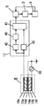
図8は上記の断線・短絡検出のための回路図の一例を示したものである。図中、Psは圧電センサ8、r1は断線検出用の抵抗体で、上述のように一対の電極14の間(図中、p1とp2)に接続されている。r1は他の抵抗r2を介して電源Vdと接続されている。r3、r4は圧電センサ8からの信号導出用の抵抗、Q1はインピーダンス変換用のFETである。
【0025】
次に図に基づいて挟み込み防止装置としての動作、作用について説明する。
【0026】
図1において、例えば窓ガラス1が下方に有り開閉部7が開口されている状態で、車両内に設置されたパワーウィンドウの駆動スイッチを作動させ駆動手段3が作動して窓ガラス1が閉じられようとする最中に、人体の一部や鞄などのような物体が圧電センサ8に接触する場合を想定する。物体の接触により図3(b)のように接触荷重12が圧電センサ8に加わり、変位L2が生じて圧電材13自身に歪が生じるので、圧電効果により歪に応じ図6のような電圧が発生する。発生する電圧レベルは接触時の変位の大きさと、圧電センサ8自体の感度、すなわち圧電材13の圧電定数などにより変化する。
【0027】
次に、圧電センサ8から発生した信号は接触検出手段17のインピーダンス変換部19で低インピーダンスに変換される。インピーダンス変換された信号は第1の濾波部20と第2の濾波部21で濾波される。図9に第1の濾波部20と第2の濾波部21の濾波特性を示す。図中、縦軸はパワーPw、横軸は周波数fである。同図において、物体の接触、特に人体の一部が接触する場合には主に低周波のf1を中心とする出力信号が圧電センサ8から出力される。そのため、第1の濾波部20の濾波特性をf1としている。また、本実施例のように車両のパワーウィンドウへの適用の場合には、主にエンジンや走行による振動等によるf2(>f1)を中心とする車両自体の振動がノイズ成分として圧電センサ8に重畳してくるため、第2の濾波部21ではこの成分を捉えるため、濾波特性をf2としている。次に、接触判定部22では上記2つの濾波部からの濾波信号に基づき物体の接触の判定を行う。
【0028】
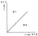
図10はその判定基準を図示したものである。横軸は第2の濾波部21からの出力信号Vf2、縦軸は第1の濾波部20からの出力信号Vf1である。同図において、領域D1のようにVf1/Vf2の値が大きい場合は物体が接触したと判定し、領域D2のようにVf1/Vf2の値が小さい場合は接触なしと判定する。
【0029】
図11は上記の判定の手順を示した判定フロー図である。ステップ23でパワーウィンドウのSWがオンされると、ステップ24で駆動手段が作動し、ステップ25でVf1及びVf2が算出され、ステツプ26でVf1とVf2の比kが算出される。次にステップ27でkが予め定められた設定値k0と比較され、k>k0ならばステップ28で物体の接触ありと判定され、ステップ29で駆動手段が停止される。またステップ27でk>k0でないならばステップ30で接触なしと判定され、ステップ31で窓の閉め切りが検知されるまでステップ25以降の処理が継続される。窓の閉め切りの検知は、例えば窓の閉め切りの際に駆動手段のモータに印加される電流値がある一定値以上になることを検出して行う。ステップ29では駆動手段を逆転させて窓を下降するようにしても良い。
【0030】
上記では2つの濾波部を設けたが、濾波部は2つに限定するものではなく、挟み込みを検出するよう適用事例に応じて濾波部の特性や個数を最適化することも可能である。特に圧電センサ8の変形部位の曲率半径を小さくすることにより、物体が接触する場合の出力信号レベルが、車両の振動ノイズ等のレベルよりはるかに大きくなる場合は濾波部が一つでも良いし、場合によっては濾波部を用いなくてもよい。また、kの値は車両の振動特性等を考慮して事前に実験等により最適化すればよい。
【0031】
また、図8のように抵抗体r1を介して電極間に電圧を印加して出力VO1をモニタすることにより電極の断線を検出することができる。すなわち、図8において正常時のVO1は、電源電圧Vdに対して、r1、r2、r3の分圧値となる。圧電センサ8の電極が断線した場合に等価的に点p1または点p2がオープンとなるとすれば、VO1はr2、r3の分圧値となる。電極がショートすると等価的にはp1、p2がショートすることになるので、V1は0になる。このようにV1の値に基づいて圧電センサ8の電極の断線やショートといった異常を検出することができ、信頼性を向上することができる。
【0032】
以上の作用により、圧電センサの出力信号に基づき物体の接触を検出した時点で開閉部の開閉動作を停止することができる上、圧電センサは物体との接触により生じる歪を電気的な信号に変換して出力するので、雨や洗車等により圧電センサが濡れても誤検出がなく精度良く挟み込みを検知することができる。また圧電センサは感圧スイッチのような接点がないので、接触不良や短絡がなく耐久性のよい挟み込み防止装置を実現できる。
【0033】
また本実施例のように、圧電センサを窓枠側即ち当接部材に配設すれば、開閉に際して移動しないのでリード線の保持等が容易である。
【0034】
なお、圧電センサを窓ガラス側即ち移動部材側に配設してもよい。この場合は挟み込み時に間違いなく接触するため、検知ミスや検知遅れが起こりにくい効果がある。また同様に、自動車の場合は窓枠よりも窓の方が位置的に低く物体が挟み込まれる時には窓枠よりも窓ガラスに先に接触する場合が多いと考えられるので、窓ガラス側のみの接触で早めに検知することができて、挟み込まれる前に停止できる可能性が高く、より安全性が高い。
【0035】
また本実施例では、接触検出手段が圧電センサから出力される信号のうち物体の接触時に発生する特定周波数成分のみを検出するので、例えば開閉部の開閉動作による振動や外来振動など物体の接触以外の振動による圧電センサの出力信号と物体の接触による出力信号とを区別して物体の接触を検出することができ、検出精度が向上する。
【0036】
また開閉位置検出部から出力される開閉位置信号が予め定められた設定範囲にある場合にのみ物体が接触したかどうかの出力信号を有効とすれば、開閉位置が上記設定範囲を越えて正常に開閉部が閉め切られている場合には、圧電センサから信号が出て接触検出手段が物体の接触有りと検出しても、その検出信号を無視して不要な開放を防止することができる。
【0037】
また圧電センサがセンサ先端側の電極間にセンサの断線や短絡を検出するための抵抗体を備え、抵抗体を介して電極間に電圧を印加してモニタすることにより電極の断線や短絡を検出することができるので信頼性を向上することができる。
【0038】
なお上記実施例では圧電センサを1本配設したが、たとえば2本配設すれば以下のような効果が生じる。
【0039】
まず1本を挟み込みの検知用に開閉部に配設し、他の一本を車両の振動の検知用に配設すれば、両者の出力の差をとることで車両の振動による出力だけが相殺できて挟み込みの検知精度が向上する。
【0040】
また移動部材側と当接部材側のそれぞれに配設し、両者ともに挟み込みの出力を発生した場合のみ駆動手段の駆動を停止するようにすれば、挟み込み防止の精度が向上する。たとえば全開の状態から窓ガラスが上昇し始めた時に運転手の指が触れた程度では挟み込みには至らないので本来停止させる必要は無い(停止してしまうと再度スイッチを押さなければならない)。このような場合には停止させず、本当に挟み込まれた時のみ停止させることができる。
【0041】
また本実施例のように、圧電材をゴム弾性体に圧電セラミックを混合して形成すれば、圧電セラミックは脱分極の耐熱性に優れているので、高温となる場所(たとえば直射日光にさらされる場所)に配設することができる。例えば窓枠やウエザストリップ(図2の32)の室外側とかサイドバイザー(日除け用のひさし)等、外界に暴露される場所に配設しても耐久性がよく、物体の接触を検出する際の信頼性が向上する。また、圧電材と電極のそれぞれにゴム弾性体を使用しているので加工性がよく任意の形状に対応可能である。
【0042】
ここで、本実施例の圧電材(有機基材は塩素化ポリエチレン、圧電セラミックはチタン酸ジルコン酸鉛の焼結粉体)と、特開平10−76843号公報、特開平10−132669号公報などに示される従来のポリフッ化ビニリデン(PVDF)を比較するために、それぞれ2畳程度のサイズに成型して床に設置し、発熱体で圧電材の温度が100℃になるように調節しながら経過時間ごとに人が入床した時の発生電圧を測定比較した。この時の被験者の体重は63kgで、発熱させる前の初期の本実施例及び従来品における入床時の発生電圧は共に200mVになるよう設計した。この結果を図12に示す。横軸に経過時間、縦軸に発生電圧をとっており、本実施例の圧電材の発生電圧aは径時変化がなくほぼフラットな特性であるが、従来の圧電材の発生電圧bは徐々に電圧が低下してくる。つまり本実施例の圧電材の方が従来の圧電材よりも長時間、安定的に感度を維持できる。
【0043】
これは、従来はポリフッ化ビニリデンフィルムを使用しているので、100℃の高温中に長時間放置されていると、電圧が発生する方向に配向していたポリフッ化ビニリデンの分子結晶が乱れて結晶構造が変化し、次第に発生電圧が低下してくるためと思われる。これに対して、本実施例のチタン酸ジルコン酸鉛焼結粉体の耐熱性は300℃〜350℃であるので、100℃中に放置しても分極した結晶構造は変化せず、感度が安定的に維持できると考えられる。
【0044】
なお、この実施例ではチタン酸ジルコン酸鉛の焼結粉体を使用したが、耐熱性が高いもので、かつ分極による結晶構造の配向性、即ち、圧力荷重に対して電圧を発生する性質(ピエゾ性)を有するものであれば、たとえばチタン酸鉛の焼結粉体を使用しても本実施例と同様の結果を得ることができる。
【0045】
なお、使用温度が低い場合は従来と同じくポリフッ化ビニリデンフィルムを使用してもよい。
【0046】
なお、電極は導電ゴムに限られるものではなく、銅、アルミ等の金属箔や導電性塗料などでもよいが、可撓性を持たせる意味ではより薄い方が望ましい。
【0047】
(実施例2)
図13〜図15に本発明の実施例2の圧電センサの構成図を示す。図13において圧電センサ8は切込み部33を有し、厚みの薄い部位34を形成している。圧電センサ8は剛体35に両端を固定されているが、剛体35の中央部分には空隙36があり、圧電センサ8の中央部が上向きに変位するのを妨げない構成である。図14(a)は従来の圧電センサ8を用いた場合、図14(b)は本実施例の圧電センサ8を用いた場合の要部断面構成図を示す。本実施例の変形部位の曲率半径はR31、R32と表せる。同一の接触荷重12を与えた場合、薄い部位34が撓みやすいので全体としての曲率半径が小さくなり(R31<R11、R32<R12)、変位量をL3とすると、L3>L1と大きくなる。圧電センサ8は、変位が大きくなると、ひずみが増え、発生する電荷が増え、分極電流が増加して、出力が大きくなるものである。本実施例においては、圧電センサ8が局部的に薄い部位34を有することで、物体の接触によって生じる変形部位の曲率半径を小さくし、変位を大きくして、出力を大きくしているのである。
【0048】
本実施例では、圧電センサ8の配設場所に空隙36を有するので、上向きの変位を妨げることがなく、より一層出力を大きくすることができる。
【0049】
図15には圧電センサ8の実施例を斜視図で示している。図15(a)は圧電センサ8をキャタピラ状にしたもので、図15(a)の奥行き方向の切込み部33により局部的な薄い部位34を形成している。本実施例では変形時に特に左右方向の曲率半径が小さくなるので、微少な面積の物体に限らず、奥行き方向に長い形状の物体(自動車の挟み込み防止装置の場合は指や腕等)が接触しても出力を大きくすることができる。
【0050】
図15(b)は他の実施例で、切込み部33を奥行き方向と幅方向とに構成して薄い部位34を形成している。本実施例では変形時に左右方向にも前後方向にも曲率半径が小さくなるので、あらゆる形状の物体で出力を大きくすることができる。
【0051】
(実施例3)
図16に本発明の実施例3の圧電センサの構成図を示す。圧電センサ8は切込み部33を上側だけでなく下側にも設けて、厚みの薄い部位34を形成している。本実施例の圧電センサ8によると、物体との接触面側にも切込み部33があるので物体との接触面積が小さくなる。物体との接触により全く同じ大きさの荷重を受ける場合、接触面積が小さい方が単位面積当たりの荷重(圧力)は大きくなるので、変位はさらに大きくなり、より出力を大きくできる。
【0052】
なお本実施例では上側の切込み部33と下側の切込み部33を薄い部位34に対向させる配置にしているが、これに限定されるものではない。
【0053】
(実施例4)
図17、図18に本発明の実施例4の圧電センサ8の構成図を示す。図17は圧電センサ8の要部の断面および配設構成を示しており、圧電センサ8は孔37を有し、剛体35に緩衝材10を介して配設する構成である。圧電センサ8は孔37により可撓性が向上するため、孔の無い場合と比べると物体との接触による変形部位の曲率半径が小さくなる。
よって変位を大きくして出力を大きくすることができる。
【0054】
本実施例では圧電センサ8を緩衝材10に配設しているが、緩衝材10は衝撃吸収の効果があるため、圧電センサ8の強度面の信頼性を向上できる。
【0055】
図18には圧電センサ8の実施例を斜視図で示している。図18(a)は圧電センサ8を格子状にしたもので孔37形状は四角形であり、図18(b)は圧電センサ8にパンチング状に円形の孔37を形成したものである。いずれの場合も、孔37の大きさを接触する物体よりも小さくしており、物体が孔37に入り込まないようにしている。
【0056】
なお圧電センサ8と物体との間で、孔が無いかもしくは孔が小さい別の部材で圧電センサ8を覆うようにすれば孔37を大きくすることができる。
【0057】
なお緩衝材と孔が無いかもしくは孔が小さい別の部材とを一体に構成し、圧電センサ8をくるむようにしてもよいし、圧電センサ8を緩衝材の内部に構成してもよい。また緩衝材として、図2のウエザストリップ32やサイドバイザー(図示せず)を兼用してもよい。この場合は部品点数、組立て工程を削減できる。
【0058】
(実施例5)
図19に本発明の実施例5の圧電センサ8の断面構成図を示す。本実施例の圧電センサ8は幾度か折り返したアコーデオン形状(蛇腹形状)であり、図19(a)は物体と接触前、図19(b)は物体と接触後の様子を示している。本実施例の圧電センサ8の変形部位の曲率半径は、全体としてみるとR41、R42のように表せる。同一の接触荷重12を与えた場合、アコーデオン形状は伸縮しやすいので全体として変形部位の曲率半径R41、R42が小さくなり(R41<R11、R42<R12)、変位量をL4とすると、L4>L1と大きくなる。圧電センサ8は、変位が大きくなると、ひずみが増え、発生する電荷が増え、分極電流が増加して、出力が大きくなるものである。本実施例においては、圧電センサ8をアコーデオン形状とすることで、物体の接触によって生じる変形部位の曲率半径を小さくし、変位を大きくして、出力を大きくしているのである。
【0059】
本実施例によると圧電センサ8は上下方向だけでなく横方向への伸縮性もあり、引っ張りながら配設したり圧縮しながら配設したり湾曲させて配設したりできるなど、配設の自由度が極めて高い。
【0060】
(実施例6)
図20に本発明の実施例6の圧電センサ8の配設構成図を示す。本実施例の圧電センサ8は中空状に構成しており、空隙36を圧電センサ8で覆ったような構成である。本実施例によれば、圧電センサ8を剛体35に直接配設しても、内部に空隙36を有する中空状
であるために可撓性が維持され、物体との接触による変形部位の曲率半径R51、R52を小さくでき、変位量L5を大きくして、出力を大きくすることができる。
【0061】
(実施例7)
図21、図22に本発明の実施例7を示す。図21は挟み込み防止装置として圧電センサ8を窓ガラス1に装着した構成図、図22は図21の圧電センサ8の断面図を拡大したものである。本実施例の圧電センサ8は、内層電極14aと外層電極14bとの間に圧電材13を配設した同軸ケーブル状、かつ中心部に空隙36を有する中空状に構成されている。
【0062】
さらに本実施例では、たとえばゴムなどの可撓性のある被覆材38で圧電センサ8を被覆しながら窓ガラス1に固定しており、本実施例の場合は接触荷重12は下向きとなり、被覆材38を介して圧電センサ8に伝えられるものである。圧電センサ8は中空状であるために可撓性が向上し、物体との接触による変形部位の曲率半径が小さくなり、変位量が大きくなり、出力を大きくすることができる。
【0063】
本実施例の圧電センサ8は、外層電極14bが電気的なシールド層を兼ねることができる。
【0064】
(実施例8)
図23は本発明の実施例8の挟み込み防止装置の動作ブロック図である。図23では圧電センサ8の断面も示している。本実施例は、他の実施例の圧電センサ8を積層フィルム状にして以下の構成に置き換えたものである。電極14cと14d、14eと14fを備えた2つの圧電材13a、13bを積層して成形され、圧電センサ8を構成する一方の圧電材13bの電極14eと14fに特定周波数の電圧信号を印加して振動を発生させる信号印加部39を備え、接触検出手段17は、前記振動により他の圧電材13aの電極14cと14d間に発生する出力信号に基づき圧電センサ8に印加される圧力を演算する圧力演算部40と、圧力演算部40の出力信号に基づき物体の接触を判定する接触判定部41とを備えたところにある。接触検出手段17は、信号印加部39の発生周波数f3を中心周波数とする第1のバンドパスフィルタ42と、図9のf1を中心周波数とする第2のバンドパスフィルタ43を備えている。本実施例の圧電センサ8はフィルム状なので、積層しても厚みは薄いので、変形部位の曲率半径を小さいまま維持できる。よって変位を大きくして、出力を大きくすることができる。
【0065】
なお、圧電センサ8の外側についてはPET等の保護層や電気的シールドのための金属フィルムで封止してもよい。
【0066】
次に動作、作用について説明する。
【0067】
一言で言えば、他の実施例では圧電センサの出力発生により挟み込みを検知していたのに対し、本実施例は圧電センサの出力の変化により挟み込みを検知するものである。
【0068】
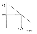
圧電センサ8では信号印加部39で発生する周波数f3の電圧信号に応じて圧電材13bが振動する。そしてその振動に応じて圧電材13aでは圧電起電力が発生する。発生した出力信号は第1のバンドパスフィルタ42で濾波される。この時の信号印加部39の発振信号V3、第1のバンドパスフィルタ42の出力V4の信号波形は、それぞれ図24(a)、図24(b)のようになる。図24(a)、図24(b)で縦軸はV3とV4、横軸は時間tで、時刻t1で物体が圧電センサ8に接触して圧力Pr1が印加されたものとする。物体が接触していない状態(t<t1)では、V4の振幅はD40である。そして時刻t1で物体が接触し圧電センサ8に圧力Pr1が印加されると、V4の振幅はD41に変化する。ここで、V4の振幅D4と圧力Prとの間には図25に示すような関係があり、圧力Prが増加するとD4は減少する特性をもつ。この特性は発振周波数f3や圧電材13a、13bの形状等により変化するので、用途に応じて予め実験等により最適化すればよい。圧力演算部40では図25の関係に基づいてD41からPr1を算出する。そして接触判定部41ではPr1がある閾値Pr0以上ならば物体が接触したと判し、Pr1がPr0より小ならば物体の接触は無いと判定する。そして窓ガラスなどの移動部材の閉動作中に上記のようにして物体の接触が検出されると、閉動作を逆転し物体の挟み込みを防止するのである。本実施例では圧電センサをフィルム状に薄く構成して変形部位の曲率半径を小さくしたので、振幅D4が全体に大きくなり、Pr1の変化を見るのが容易となるので、判定の精度を上げることができる。
【0069】
上記作用により、例えば車両の走行時の振動が圧電センサ8に印加される場合は、実施例1のように圧電センサ8が振動や歪みを検出するタイプであると、走行振動による圧電センサ8の出力信号と物体の接触による圧電センサ8の出力信号との区別が困難となる場合があるが、本実施例の圧電センサ8は物体の接触圧に応じた信号を出力し、接触検出手段17の圧力演算部40により物体の接触圧を検出し、接触判定部41により接触を判定するので、上記のような走行振動が印加されても精度よく物体の接触を検出することができる。
【0070】
尚、接触判定部41ではPr1がある閾値Pr0以上ならば物体が接触したと判定するが、Pr1の変化率や変動パターンに基づき物体の接触を判定するようにしてもよい。
【0071】
また、図23に示すように接触検出手段17はf1を中心周波数とする第2のバンドパスフィルタ43を備えており、接触判定部41が第2のバンドパスフィルタ43と圧力演算部40の双方の出力信号に基づき物体の接触を検出する構成としてもよい。この構成による作用を以下に述べる。図24(c)は第2のバンドパスフィルタ43の出力V5の信号波形を示したものである。図中、縦軸はV5、横軸は時間tである。時刻t1で圧電センサに物体が接触すると、圧電材13aには圧電材13aによる周波数f3の振動と、物体の接触による歪みによりf3よりも低いf1近傍の振動が印加され、圧電材13aからはf3とf1の重畳した周波数成分をもつ信号が出力される。この出力信号に基づき、圧力演算部40では第1のバンドパスフィルタ42経由で上述したように圧力Prが算出され、第2のバンドパスフィルタ43の出力V5には例えば図24(c)のような周波数f1で振幅D5の信号が現れる。そして接触判定部41では、例えばD5がある閾値D50以上の場合は、圧電センサ8に車の走行振動のような外来振動が印加されたとして、上述のようにPrの値に基づき物体の接触を判定する。またD5がD50より小の場合は、D5の変化率や変動パターンとPrの値の少なくとも1つに基づき物体の接触を判定する。
これにより、外来振動の有無を圧電センサ8の出力信号により判定し、外来振動の有無に応じて接触判定の閾値を切り替えて接触判定を行うので、圧電センサにより検出する振動のみあるいは圧力のみで物体の接触を検出する場合よりも検出精度が向上する。
【0072】
なお、上記各実施例の構成はそれぞれが限定された構成ではなく、他の実施例で示された構成に一部置き換えたり、組み合わせたりすることが可能であり、目的に応じて最適な組み合わせを選べばよい。
【0073】
なお、自動車の挟み込み防止装置における圧電センサの配置に関しては、窓枠側の車体、ウエザストリップ、サイドバイザー等に配設したり一体化しても良いし、窓ガラス側に配設しても良い。ハードトップタイプの場合は窓枠の代わりに車両本体側に配設してもよい。
【0074】
なお、上述の実施例では車両用のパワーウインドウに圧電センサを用いた挟み込み防止装置について説明したが、窓に限らずドアやサンルーフなどの扉に使用してもよいし、シャッターに使用してもよい。基本的には移動部材の移動により当接部材との隙間が変化するもの、即ち何らかの物体を挟み込む可能性の有るものに応用できる。
【0075】
なお電車のドアや玄関の自動ドアなどの場合、2つの移動部材が対向しているように考えられるが、一方の移動部材から見た他方を当接部材と置くことで本発明に含まれるものである。
【0076】
【発明の効果】
以上説明したように本発明の請求項1に係る挟み込み防止装置は、圧電センサを、圧電材の両面に形成された電極と、電極を覆う絶縁体と、絶縁体を覆うシールド部材により構成し、かつ少なくとも物体の接触により荷重を受ける部分に圧電材及び電極が配置されるよう緩衝材を介して配設し、前記圧電材を有する部分の圧電センサの厚みが前記圧電材を有しない部分の圧電センサの厚さより薄くし、さらに物体の接触により荷重を受ける部分の圧電材の厚さを、物体の接触により荷重を受けない部分の圧電材の厚さより薄くした。これにより、同一荷重に対する変位は大きくなり(即ち変形しやすくなり)、ひずみが増え、発生電荷が増え、分極電流が増加して、出力が大きくなる効果がある。
【0077】
また、少なくとも接触部位を薄くしたので変形しやすく、容易に変形部位の曲率半径が小さくなり、出力が大きくなる効果がある。
【0078】
また、本発明の請求項2にかかる挟み込み防止装置は、アコーデオン形状なので変形しやすく、容易に変形部位の曲率半径が小さくなり、出力が大きくなる効果がある。
【図面の簡単な説明】
【図1】 本発明の実施例1における圧電センサおよび挟み込み防止装置の外観図
【図2】 同装置のA−A線位置での断面図
【図3】 (a)従来の圧電センサの断面図
(b)本発明の実施例1における圧電センサの断面図
【図4】 同圧電センサの断面図
【図5】 同圧電センサの外観構成図
【図6】 同圧電センサの特性図
【図7】 同挟み込み防止装置のブロック図
【図8】 同装置の断線検出用の回路図
【図9】 同装置の第1の濾波部と第2の濾波部の濾波特性を示す特性図
【図10】 同装置の開閉部への物体の接触を判定するための判定基準を示した特性図
【図11】 同装置の動作を表すフローチャート
【図12】 同装置の圧電材と従来の圧電材の発生電圧の経過時間に対する変化を比較した特性図
【図13】 本発明の実施例2における圧電センサの配設構成を示す断面図
【図14】 (a)従来の圧電センサの断面図
(b)本発明の実施例2における圧電センサの断面図
【図15】 (a)同圧電センサの構成図
(b)本発明の他の実施例における圧電センサの構成図
【図16】 本発明の実施例3における圧電センサの配設構成を示す断面図
【図17】 本発明の実施例4における圧電センサの配設構成を示す断面図
【図18】 (a)同圧電センサの構成図
(b)本発明の他の実施例における圧電センサの構成図
【図19】 (a)本発明の実施例5における圧電センサの物体が接触する前の断面図
(b)同圧電センサの物体が接触した後の断面図
【図20】 本発明の実施例6における圧電センサの配設構成を示す断面図
【図21】 本発明の実施例7における圧電センサの配設構成を示す断面図
【図22】 同圧電センサの断面図
【図23】 本発明の実施例8における挟み込み防止装置の動作ブロック図
【図24】 (a)同装置の信号印加部の発振信号V3の波形特性図
(b)第1のバンドパスフィルタの出力V4の波形特性図
(c)第2のバンドパスフィルタの出力V5の出力波形を示した波形特性図
【図25】 同装置の第1のバンドパスフィルタの出力V4の振幅D4と圧力Prとの関係を示した特性図
【符号の説明】
1 窓ガラス(移動部材)
5 制御手段
6 窓枠(当接部材)
7 開閉部
8 圧電センサ
9 物体
11 接触部位
34 薄い部位
R11、R12、R21、R22、R31、R32、R41、R42、R51、R52 変形部位の曲率半径[0001]
BACKGROUND OF THE INVENTION
The present invention relates to a piezoelectric sensor that generates an output by contact of an object, and a pinching prevention device that detects and prevents the object from being caught in an opening / closing part such as a window, door, or shutter using a piezoelectric sensor.
[0002]
[Prior art]
In this type of conventional piezoelectric sensor and pinch prevention device, as described in JP-A-10-76843 and JP-A-10-132669, a cable-shaped or film-shaped piezoelectric sensor is disposed in a window or a window frame. Some of them detect the pinching of an object by generating an output from a piezoelectric sensor. Since the piezoelectric sensor generates an electric charge proportional to the applied stress (strain), it is possible to detect contact due to the object being caught by taking it out as a polarization current.
[0003]
[Problems to be solved by the invention]
However, conventional piezoelectric sensors and pinching prevention devices have the following problems.
[0004]
The piezoelectric sensor is electrically close to the capacitor C, and if a resistor R is connected in parallel to the output end, it becomes a high-pass filter having a cutoff frequency fc (= 1 / (2πCR)).
On the other hand, the output signal due to the contact of the object is generally a low frequency signal of several tens of Hz or less, so that if the signal is processed by a high pass filter, the output level may be significantly reduced. Therefore, it is necessary to increase the resistance R as much as possible to lower the cut-off frequency fc. However, when the resistance is higher than 1 MΩ, it is expensive and difficult to handle noise countermeasures. For this reason, a practically high resistance must be employed, and the output level may be sacrificed somewhat. In addition, although the piezoelectric sensor depends on the piezoelectric material and shape, the output impedance is very high and the output voltage tends to be low originally. Therefore, after receiving by an impedance conversion circuit such as an FET, processing such as significantly increasing the gain must be performed by an amplifier circuit.
[0005]
After all, the conventional piezoelectric sensor and the anti-pinch device have a problem that the output is small.
[0006]
[Means for Solving the Problems]
In order to solve the above-described problems, the piezoelectric sensor and the pinching prevention device of the present invention include a piezoelectric sensor disposed in an opening / closing portion configured by a moving member and a contact member, and the opening / closing operation based on an output of the piezoelectric sensor. Control means for controlling the opening / closing operation of the opening / closing part by detecting the object sandwiched in the part, the piezoelectric sensor comprising electrodes formed on both surfaces of the piezoelectric material, an insulator covering the electrode, and the insulator Of the piezoelectric sensor of the portion having the piezoelectric material, which is disposed through a buffer material so that the piezoelectric material and the electrode are disposed at least in a portion that receives a load due to contact with the object. The thickness is made thinner than the thickness of the piezoelectric sensor in the portion that does not have the piezoelectric material, and the thickness of the piezoelectric material in the portion that receives the load due to the contact with the object is the pressure of the portion that does not receive the load due to the contact with the object. Is obtained is characterized in that thinner than the thickness of the wood.
[0007]
According to the above invention, when the radius of curvature of the deformed portion is small, the displacement with respect to the same load increases, the strain increases, the generated charge increases, the polarization current increases, and the output increases.
[0008]
DETAILED DESCRIPTION OF THE INVENTION
According to a first aspect of the present invention, there is provided a pinching prevention device comprising: a piezoelectric sensor disposed in an opening / closing portion composed of a moving member and a contact member; and an object being caught in the opening / closing portion based on an output of the piezoelectric sensor. The piezoelectric sensor comprises an electrode formed on both surfaces of the piezoelectric material, an insulator covering the electrode, and a shield member covering the insulator. The piezoelectric material and the electrode are disposed through a buffer material so that the piezoelectric material and the electrode are disposed at least in a portion that receives a load due to contact with the object, and the thickness of the piezoelectric sensor in the portion having the piezoelectric material is the thickness of the piezoelectric material. The thickness of the piezoelectric sensor in the part that does not have the thickness is made thinner, and the thickness of the piezoelectric material in the part that receives the load due to the contact with the object is made thinner than the thickness of the piezoelectric material in the part that does not receive the load due to the contact with the object. It is obtained by the features.
[0009]
Claims of the
[0010]
And since it is an accordion shape, it is easy to deform | transform, the curvature radius of a deformation | transformation site | part becomes small easily, and an output becomes large.
[0011]
【Example】
Embodiments of the present invention will be described below with reference to the drawings.
[0012]
(Example 1)
FIG. 1 shows an external view of a pinching prevention device according to
[0013]
FIG. 2 is a cross-sectional view taken along line AA in FIG. FIG. 2 shows a state in which the
[0014]
FIG. 3 is a cross-sectional configuration diagram of a main part of the
[0015]
FIG. 4 is a cross-sectional configuration diagram of a principal part showing in detail the
[0016]
In the
[0017]
Further, in this embodiment, the
Can be converted to a position.
[0018]
Alternatively, the entire
[0019]
In addition, you may make it the structure which extended the
[0020]
FIG. 5 is a configuration diagram of the
[0021]
FIG. 6 is an output characteristic diagram of the piezoelectric sensor of this embodiment. If an object (for example, a driver's finger) is sandwiched between the
[0022]
FIG. 7 is a block diagram showing the circuit processing of this embodiment. A
[0023]
Although not shown, a resistor for detecting disconnection / short circuit between the
[0024]
FIG. 8 shows an example of a circuit diagram for detecting the disconnection / short circuit. In the figure, Ps is the
[0025]
Next, the operation and action of the pinching prevention device will be described with reference to the drawings.
[0026]
In FIG. 1, for example, in a state where the
[0027]
Next, the signal generated from the
[0028]
FIG. 10 illustrates the determination criteria. The horizontal axis represents the output signal Vf2 from the
[0029]
FIG. 11 is a determination flowchart showing the above-described determination procedure. When the SW of the power window is turned on in
[0030]
In the above description, two filtering units are provided. However, the number of filtering units is not limited to two, and it is possible to optimize the characteristics and number of filtering units according to application examples so as to detect pinching. In particular, by reducing the radius of curvature of the deformed portion of the
[0031]
Further, as shown in FIG. 8, disconnection of the electrode can be detected by applying a voltage between the electrodes via the resistor r <b> 1 and monitoring the output VO <b> 1. That is, in FIG. 8, VO1 at normal time is a divided voltage value of r1, r2, and r3 with respect to the power supply voltage Vd. If the point p1 or the point p2 is equivalently opened when the electrode of the
[0032]
With the above action, the opening / closing operation of the opening / closing part can be stopped when the contact of the object is detected based on the output signal of the piezoelectric sensor, and the piezoelectric sensor converts the distortion caused by the contact with the object into an electrical signal. Therefore, even if the piezoelectric sensor gets wet due to rain, car washing or the like, it is possible to detect pinching with high accuracy without erroneous detection. In addition, since the piezoelectric sensor does not have a contact point like a pressure-sensitive switch, it is possible to realize a pinching prevention device that has no contact failure or short circuit and has high durability.
[0033]
If the piezoelectric sensor is disposed on the window frame side, that is, the contact member as in this embodiment, the lead wire can be easily held because it does not move during opening and closing.
[0034]
The piezoelectric sensor may be disposed on the window glass side, that is, on the moving member side. In this case, there is no doubt that detection mistakes and detection delays are unlikely to occur because the contact is definitely made during the pinching. Similarly, in the case of an automobile, the window is lower in position than the window frame, and when objects are caught, it is considered that the window glass often comes in contact with the window glass first, so that only the window glass side contacts. Can be detected early, and it is highly possible that the vehicle can be stopped before being caught.
[0035]
In this embodiment, since the contact detection means detects only a specific frequency component generated when the object is in contact with the signal output from the piezoelectric sensor, for example, other than the object contact such as vibration due to the opening / closing operation of the opening / closing part or external vibration. It is possible to detect the contact of the object by distinguishing the output signal of the piezoelectric sensor due to the vibration and the output signal due to the contact of the object, and the detection accuracy is improved.
[0036]
In addition, if the output signal indicating whether or not an object has contacted is made valid only when the open / close position signal output from the open / close position detection unit is within a predetermined set range, the open / close position will normally exceed the set range. When the opening / closing part is closed, even if a signal is output from the piezoelectric sensor and the contact detection means detects that there is contact with an object, the detection signal can be ignored to prevent unnecessary opening.
[0037]
In addition, the piezoelectric sensor is equipped with a resistor for detecting the disconnection or short circuit of the sensor between the electrodes on the tip side of the sensor. By monitoring the voltage applied between the electrodes via the resistor, the disconnection or the short circuit of the electrode is detected. Therefore, reliability can be improved.
[0038]
In the above embodiment, one piezoelectric sensor is provided. However, if two piezoelectric sensors are provided, for example, the following effects can be obtained.
[0039]
First, if one is placed in the opening and closing part for detecting pinching and the other is placed for detecting vibration of the vehicle, only the output due to the vibration of the vehicle is canceled by taking the difference between the two outputs. This improves the pinching detection accuracy.
[0040]
Further, if the driving means is stopped only when both the moving member side and the abutting member side are disposed and both of them generate a pinching output, the pinching prevention accuracy is improved. For example, when the driver's finger touches when the window glass starts to rise from the fully open state, it is not necessary to stop it because it is not pinched (the switch must be pressed again when it stops). In such a case, it can be stopped only when it is really caught without being stopped.
[0041]
Further, as in this embodiment, if the piezoelectric material is formed by mixing a piezoelectric elastic with a rubber elastic body, the piezoelectric ceramic is excellent in heat resistance against depolarization, so that it is exposed to high temperatures (for example, exposed to direct sunlight). Place). For example, it is durable even when placed in places exposed to the outside, such as the outside of a window frame or weather strip (32 in FIG. 2) or side visor (shade for sunshade). Reliability is improved. In addition, since a rubber elastic body is used for each of the piezoelectric material and the electrode, the workability is good and it can correspond to any shape.
[0042]
Here, the piezoelectric material of this example (organic base material is chlorinated polyethylene, piezoelectric ceramic is a sintered powder of lead zirconate titanate), JP-A-10-76843, JP-A-10-132669, etc. In order to compare the conventional polyvinylidene fluoride (PVDF) shown in Fig. 2, it is molded into a size of about 2 tatami mats and placed on the floor, and the temperature is adjusted so that the temperature of the piezoelectric material becomes 100 ° C with a heating element. We measured and compared the voltage generated when a person entered the floor every hour. The weight of the subject at this time was 63 kg, and the voltage generated at the time of entering the floor in the present Example before the heat generation and the conventional product was designed to be 200 mV. The result is shown in FIG. The elapsed time is taken on the horizontal axis, and the generated voltage is taken on the vertical axis. The generated voltage a of the piezoelectric material of this example has almost no change with time, but the generated voltage b of the conventional piezoelectric material gradually increases. The voltage will decrease. In other words, the sensitivity of the piezoelectric material of this example can be stably maintained for a longer time than the conventional piezoelectric material.
[0043]
This is because a conventional polyvinylidene fluoride film is used, and if it is left for a long time at a high temperature of 100 ° C., the molecular crystal of polyvinylidene fluoride that has been oriented in the direction of voltage generation is disturbed. It seems that the structure changes and the generated voltage gradually decreases. On the other hand, since the heat resistance of the lead zirconate titanate sintered powder of this example is 300 ° C. to 350 ° C., the polarized crystal structure does not change even when left in 100 ° C., and the sensitivity is high. It is thought that it can be maintained stably.
[0044]
In this example, sintered powder of lead zirconate titanate was used, but the heat resistance is high, and the orientation of the crystal structure by polarization, that is, the property of generating a voltage against pressure load ( As long as it has a piezo property, for example, a lead titanate sintered powder can be used to obtain the same result as in this example.
[0045]
When the operating temperature is low, a polyvinylidene fluoride film may be used as in the conventional case.
[0046]
The electrode is not limited to conductive rubber, but may be a metal foil such as copper or aluminum or a conductive paint. However, it is desirable that the electrode is thinner in order to provide flexibility.
[0047]
(Example 2)
13 to 15 are configuration diagrams of the piezoelectric sensor according to the second embodiment of the present invention. In FIG. 13, the
[0048]
In this embodiment, since the
[0049]
FIG. 15 is a perspective view showing an embodiment of the
[0050]
FIG. 15B shows another embodiment, in which the
[0051]
(Example 3)
FIG. 16 shows a configuration diagram of the piezoelectric sensor according to the third embodiment of the present invention. The
[0052]
In the present embodiment, the
[0053]
(Example 4)
17 and 18 are configuration diagrams of the
Therefore, the displacement can be increased to increase the output.
[0054]
In the present embodiment, the
[0055]
FIG. 18 is a perspective view showing an embodiment of the
[0056]
If the
[0057]
The buffer material and another member having no hole or a small hole may be integrally formed to enclose the
[0058]
(Example 5)
FIG. 19 is a cross-sectional configuration diagram of the
[0059]
According to the present embodiment, the
[0060]
(Example 6)
FIG. 20 shows an arrangement configuration of the
Therefore, the flexibility is maintained, the radii of curvature R51 and R52 of the deformed part due to contact with the object can be reduced, the displacement L5 can be increased, and the output can be increased.
[0061]
(Example 7)
21 and 22 show a seventh embodiment of the present invention. FIG. 21 is a configuration diagram in which the
[0062]
Furthermore, in this embodiment, the
[0063]
In the
[0064]
(Example 8)
FIG. 23 is an operation block diagram of the pinching prevention device according to the eighth embodiment of the present invention. FIG. 23 also shows a cross section of the
[0065]
The outside of the
[0066]
Next, the operation and action will be described.
[0067]
In short, in the other embodiments, the pinching is detected by the output of the piezoelectric sensor, whereas in this embodiment, the pinching is detected by the change in the output of the piezoelectric sensor.
[0068]
In the
[0069]
For example, when the vibration at the time of traveling of the vehicle is applied to the
[0070]
The
[0071]
Further, as shown in FIG. 23, the
Accordingly, the presence or absence of external vibration is determined from the output signal of the
[0072]
The configurations of the above-described embodiments are not limited to each other, and can be partially replaced or combined with the configurations shown in other embodiments. Just choose.
[0073]
In addition, regarding the arrangement | positioning of the piezoelectric sensor in the pinching prevention apparatus of a motor vehicle, you may arrange | position to the vehicle body, weather strip, side visor, etc. by the side of a window frame, and may arrange | position to a window glass side. In the case of the hard top type, it may be arranged on the vehicle body side instead of the window frame.
[0074]
In the above-described embodiment, the pinch prevention device using the piezoelectric sensor for the power window for the vehicle has been described. Good. Basically, the present invention can be applied to a case in which the gap with the abutting member changes due to the movement of the moving member, that is, there is a possibility that some object may be sandwiched.
[0075]
In the case of a train door or an automatic door of a front door, it is considered that two moving members are facing each other. However, the moving member is included in the present invention by placing the other viewed from one moving member as an abutting member. It is.
[0076]
【The invention's effect】
As described above, in the pinching prevention device according to
[0077]
Further, since at least the contact part is made thin, it is easy to be deformed, and there is an effect that the radius of curvature of the deformed part is easily reduced and the output is increased.
[0078]
Further, the claims of the
[Brief description of the drawings]
FIG. 1 is an external view of a piezoelectric sensor and a pinching prevention device according to
FIG. 2 is a cross-sectional view taken along the line AA of the apparatus.
3A is a sectional view of a conventional piezoelectric sensor. FIG.
(B) Sectional view of the piezoelectric sensor in Example 1 of the present invention
FIG. 4 is a sectional view of the piezoelectric sensor
FIG. 5 is an external configuration diagram of the piezoelectric sensor.
FIG. 6 is a characteristic diagram of the piezoelectric sensor.
FIG. 7 is a block diagram of the pinching prevention device.
FIG. 8 is a circuit diagram for detecting disconnection of the apparatus.
FIG. 9 is a characteristic diagram showing the filtering characteristics of the first filtering unit and the second filtering unit of the apparatus.
FIG. 10 is a characteristic diagram showing a criterion for determining contact of an object with the opening / closing part of the apparatus
FIG. 11 is a flowchart showing the operation of the apparatus.
FIG. 12 is a characteristic diagram comparing changes with time in the generated voltage of the piezoelectric material of the apparatus and a conventional piezoelectric material.
FIG. 13 is a cross-sectional view showing an arrangement configuration of piezoelectric sensors in
FIG. 14A is a sectional view of a conventional piezoelectric sensor.
(B) Sectional view of the piezoelectric sensor in Example 2 of the present invention
FIG. 15A is a configuration diagram of the piezoelectric sensor.
(B) Configuration diagram of a piezoelectric sensor in another embodiment of the present invention
FIG. 16 is a cross-sectional view showing an arrangement configuration of a piezoelectric sensor according to a third embodiment of the present invention.
FIG. 17 is a cross-sectional view showing an arrangement configuration of a piezoelectric sensor in Example 4 of the present invention.
FIG. 18A is a configuration diagram of the piezoelectric sensor.
(B) Configuration diagram of a piezoelectric sensor in another embodiment of the present invention
FIG. 19A is a cross-sectional view of a piezoelectric sensor according to a fifth embodiment of the present invention before contact with an object.
(B) Sectional view after the object of the piezoelectric sensor comes into contact
FIG. 20 is a cross-sectional view showing an arrangement configuration of a piezoelectric sensor in Example 6 of the present invention.
FIG. 21 is a cross-sectional view showing an arrangement configuration of a piezoelectric sensor according to a seventh embodiment of the present invention.
FIG. 22 is a sectional view of the same piezoelectric sensor.
FIG. 23 is an operation block diagram of the pinching prevention device according to the eighth embodiment of the present invention.
24A is a waveform characteristic diagram of an oscillation signal V3 of a signal applying unit of the apparatus. FIG.
(B) Waveform characteristic diagram of output V4 of the first bandpass filter
(C) Waveform characteristic diagram showing the output waveform of the output V5 of the second bandpass filter
FIG. 25 is a characteristic diagram showing the relationship between the amplitude D4 of the output V4 of the first bandpass filter of the same device and the pressure Pr.
[Explanation of symbols]
1 Window glass (moving member)
5 Control means
6 Window frame (contact member)
7 Opening and closing part
8 Piezoelectric sensor
9 objects
11 Contact area
34 Thin parts
R11, R12, R21, R22, R31, R32, R41, R42, R51, R52 Curvature radius of deformation part
Claims (2)
前記圧電センサの出力に基づき前記開閉部への物体の挟み込みを検知し前記開閉部の開閉動作を制御する制御手段を備え、前記圧電センサは、圧電材の両面に形成された電極と、
前記電極を覆う絶縁体と、前記絶縁体を覆うシールド部材により構成され、かつ少なくとも前記物体の接触により荷重を受ける部分に前記圧電材及び前記電極が配置されるよう緩衝材を介して配設され、前記圧電材を有する部分の圧電センサの厚みが前記圧電材を有しない部分の圧電センサの厚さより薄くし、さらに物体の接触により荷重を受ける部分の圧電材の厚さを、物体の接触により荷重を受けない部分の圧電材の厚さより薄くしたことを特徴とする挟み込み防止装置。A piezoelectric sensor disposed in an opening / closing part composed of a moving member and a contact member;
Control means for controlling the opening and closing operation of the opening and closing unit by detecting the object sandwiched in the opening and closing unit based on the output of the piezoelectric sensor, the piezoelectric sensor, electrodes formed on both surfaces of the piezoelectric material,
An insulator covering the electrode and a shield member covering the insulator, and disposed via a buffer material so that the piezoelectric material and the electrode are disposed at least in a portion that receives a load due to contact with the object. The thickness of the piezoelectric sensor in the portion having the piezoelectric material is made thinner than the thickness of the piezoelectric sensor in the portion not having the piezoelectric material, and the thickness of the piezoelectric material in the portion receiving the load due to the contact with the object is reduced by the contact with the object. An anti-pinch device characterized in that it is thinner than the thickness of the piezoelectric material in the portion not receiving the load.
前記圧電センサの出力に基づき前記開閉部への物体の挟み込みを検知し前記開閉部の開閉動作を制御する制御手段を備え、前記圧電センサは出力を大きくするべく、変形部位をアコーデオン形状とすることで物体の接触によって生じる変形部位の曲率半径を小さくした挟み込み防止装置。A piezoelectric sensor disposed in an opening / closing part composed of a moving member and a contact member;
Control means for controlling the opening / closing operation of the opening / closing part by detecting the object sandwiched in the opening / closing part based on the output of the piezoelectric sensor, and the piezoelectric sensor has an accordion shape in order to increase the output. An anti-pinch device that reduces the radius of curvature of a deformed part caused by contact with an object.
Priority Applications (1)
| Application Number | Priority Date | Filing Date | Title |
|---|---|---|---|
| JP15612299A JP3719046B2 (en) | 1999-06-03 | 1999-06-03 | Anti-pinch device |
Applications Claiming Priority (1)
| Application Number | Priority Date | Filing Date | Title |
|---|---|---|---|
| JP15612299A JP3719046B2 (en) | 1999-06-03 | 1999-06-03 | Anti-pinch device |
Related Child Applications (1)
| Application Number | Title | Priority Date | Filing Date |
|---|---|---|---|
| JP2004072538A Division JP2004251911A (en) | 2004-03-15 | 2004-03-15 | Piezoelectric sensor and clipping prevention equipment |
Publications (3)
| Publication Number | Publication Date |
|---|---|
| JP2000346719A JP2000346719A (en) | 2000-12-15 |
| JP2000346719A5 JP2000346719A5 (en) | 2005-01-06 |
| JP3719046B2 true JP3719046B2 (en) | 2005-11-24 |
Family
ID=15620813
Family Applications (1)
| Application Number | Title | Priority Date | Filing Date |
|---|---|---|---|
| JP15612299A Expired - Fee Related JP3719046B2 (en) | 1999-06-03 | 1999-06-03 | Anti-pinch device |
Country Status (1)
| Country | Link |
|---|---|
| JP (1) | JP3719046B2 (en) |
Families Citing this family (2)
| Publication number | Priority date | Publication date | Assignee | Title |
|---|---|---|---|---|
| CN110261482B (en) * | 2019-07-26 | 2024-02-23 | 招商局重庆公路工程检测中心有限公司 | Roller type collector and collecting device |
| CN113682114B (en) * | 2021-10-26 | 2021-12-21 | 江苏铁锚玻璃股份有限公司 | Vehicle window glass with ventilation and purification functions |
-
1999
- 1999-06-03 JP JP15612299A patent/JP3719046B2/en not_active Expired - Fee Related
Also Published As
| Publication number | Publication date |
|---|---|
| JP2000346719A (en) | 2000-12-15 |
Similar Documents
| Publication | Publication Date | Title |
|---|---|---|
| JP3719045B2 (en) | Anti-pinch device | |
| JP2000346717A5 (en) | ||
| JP3719046B2 (en) | Anti-pinch device | |
| JP3740838B2 (en) | Anti-pinch device | |
| JP2006097463A (en) | Pinch preventing device | |
| JP3740951B2 (en) | Pinching determination device and switching device | |
| JP3680632B2 (en) | Pinching detection device and switching device | |
| JP3637918B1 (en) | Anti-pinch device | |
| JPH1076843A (en) | Device for preventing object from being pinched | |
| JP2000346719A5 (en) | ||
| JP2000321150A (en) | Pinching detection sensor and pinching-preventing device | |
| JP3891180B2 (en) | Piezoelectric sensor | |
| JP2007057542A (en) | Piezoelectric sensor | |
| JP2004251911A (en) | Piezoelectric sensor and clipping prevention equipment | |
| JP2000321150A5 (en) | ||
| JP2000346718A5 (en) | ||
| JP4761115B2 (en) | Pinching detection circuit | |
| JP3741048B2 (en) | Contact detection device and switching device | |
| JP2004198437A5 (en) | ||
| JP2000346718A (en) | Load detector for piezoelectric sensor and catching preventer | |
| JP2004168308A (en) | Piezoelectric sensor load detecting device | |
| JP3680700B2 (en) | Pressure sensor, object detection device, and opening / closing device | |
| JP2005208066A (en) | Nipping detection sensor | |
| JP3740947B2 (en) | Pinch detection device and switching device | |
| JP3664008B2 (en) | Pinching detection device and switching device |
Legal Events
| Date | Code | Title | Description |
|---|---|---|---|
| A521 | Written amendment |
Free format text: JAPANESE INTERMEDIATE CODE: A523 Effective date: 20040210 |
|
| A521 | Written amendment |
Free format text: JAPANESE INTERMEDIATE CODE: A523 Effective date: 20040312 |
|
| A977 | Report on retrieval |
Free format text: JAPANESE INTERMEDIATE CODE: A971007 Effective date: 20040402 |
|
| A521 | Written amendment |
Free format text: JAPANESE INTERMEDIATE CODE: A821 Effective date: 20040312 |
|
| A871 | Explanation of circumstances concerning accelerated examination |
Free format text: JAPANESE INTERMEDIATE CODE: A871 Effective date: 20040413 |
|
| A975 | Report on accelerated examination |
Free format text: JAPANESE INTERMEDIATE CODE: A971005 Effective date: 20040813 |
|
| A131 | Notification of reasons for refusal |
Free format text: JAPANESE INTERMEDIATE CODE: A131 Effective date: 20040824 |
|
| A521 | Written amendment |
Free format text: JAPANESE INTERMEDIATE CODE: A523 Effective date: 20041022 |
|
| A131 | Notification of reasons for refusal |
Free format text: JAPANESE INTERMEDIATE CODE: A131 Effective date: 20041221 |
|
| A521 | Written amendment |
Free format text: JAPANESE INTERMEDIATE CODE: A523 Effective date: 20050210 |
|
| A131 | Notification of reasons for refusal |
Free format text: JAPANESE INTERMEDIATE CODE: A132 Effective date: 20050510 |
|
| RD01 | Notification of change of attorney |
Free format text: JAPANESE INTERMEDIATE CODE: A7421 Effective date: 20050629 |
|
| A521 | Written amendment |
Free format text: JAPANESE INTERMEDIATE CODE: A523 Effective date: 20050704 |
|
| TRDD | Decision of grant or rejection written | ||
| A01 | Written decision to grant a patent or to grant a registration (utility model) |
Free format text: JAPANESE INTERMEDIATE CODE: A01 Effective date: 20050816 |
|
| A61 | First payment of annual fees (during grant procedure) |
Free format text: JAPANESE INTERMEDIATE CODE: A61 Effective date: 20050829 |
|
| FPAY | Renewal fee payment (event date is renewal date of database) |
Free format text: PAYMENT UNTIL: 20080916 Year of fee payment: 3 |
|
| FPAY | Renewal fee payment (event date is renewal date of database) |
Free format text: PAYMENT UNTIL: 20090916 Year of fee payment: 4 |
|
| FPAY | Renewal fee payment (event date is renewal date of database) |
Free format text: PAYMENT UNTIL: 20090916 Year of fee payment: 4 |
|
| FPAY | Renewal fee payment (event date is renewal date of database) |
Free format text: PAYMENT UNTIL: 20100916 Year of fee payment: 5 |
|
| FPAY | Renewal fee payment (event date is renewal date of database) |
Free format text: PAYMENT UNTIL: 20110916 Year of fee payment: 6 |
|
| LAPS | Cancellation because of no payment of annual fees |