JP3719013B2 - Sheet post-processing apparatus and image forming apparatus - Google Patents
Sheet post-processing apparatus and image forming apparatus Download PDFInfo
- Publication number
- JP3719013B2 JP3719013B2 JP29212598A JP29212598A JP3719013B2 JP 3719013 B2 JP3719013 B2 JP 3719013B2 JP 29212598 A JP29212598 A JP 29212598A JP 29212598 A JP29212598 A JP 29212598A JP 3719013 B2 JP3719013 B2 JP 3719013B2
- Authority
- JP
- Japan
- Prior art keywords
- sheet
- binding
- saddle stitching
- stopper member
- processing
- Prior art date
- Legal status (The legal status is an assumption and is not a legal conclusion. Google has not performed a legal analysis and makes no representation as to the accuracy of the status listed.)
- Expired - Fee Related
Links
Images


Description
【0001】
【発明の属する技術分野】
本発明は、電子写真複写機やプリンタやファクシミリ等の画像形成装置から画像形成後に排出されるシートを順次、シート後処理装置内に取り込み、このシートに綴じ(ステープル)や折り等の後処理を行い、排紙部に排出する機能を備えたシート後処理装置に関するものである。
【0002】
【従来の技術】
画像形成装置より排紙される画像記録済の複数枚の記録紙を、コピー部数ごとに丁合してステープルにより綴じ合わせる装置としてフィニッシャと呼ばれるシート後処理装置が利用される。
【0003】
このフィニッシャは、複写機やプリンタ等の画像形成装置本体と機能が接続されていて、コピーまたはプリントプロセスのシーケンス作動に対応して駆動する。
【0004】
従って画像形成プロセスを高速で処理することの可能な画像形成装置に対しては、その処理速度に追従して機能を果すことの出来る高速処理の可能なフィニッシャが必要とされる。
【0005】
このようなフィニッシャに関しては、すでに特開昭60−142359号、同60−158463号、同62−239169号さらに特開昭62−288002号、同63−267667号、特開平2−276691号、特開平8−319054号、特公平5−41991号の各公報に開示されている。
【0006】
特開昭60−183459号公報の製本装置は、表紙供給装置を有し、複写紙群と表紙とを重ね合わせた後、穴開け又はステープル綴じ等の製本仕上げ作業を行うものである。
【0007】
特開平6−72064号、同7−187479号、同8−192951号各公報は、中綴じ処理機能を有するシート後処理装置である。
【0008】
特開平10−148983号公報の用紙処理装置は、用紙を二つ折りするための紙折り手段を有する用紙処理装置である。
【0009】
【発明が解決しようとする課題】
(1)従来のシート後処理装置は、平綴じモード用の可動ストッパ部材の駆動源(モータ等)と、中綴じ用の可動ストッパ部材の駆動源(モータ等)とが、個別に設けられているため、製造コストアップとなっている。
【0010】
(2)駆動源にステッピングモータを使用する場合、外力により位相ずれを発生することがあるから、駆動開始に先立って駆動開始可能位置に位置決めするための初期化動作を実施しなければならない。ある部分の動作に連動して他の部分を動作させる場合に、各初期化動作の順番を限定する必要がある。もし、これらの順序を誤ると動作部材間で干渉を発生し、装置の故障を発生する。これを防止するためには、装置の駆動系が複雑になる欠点がある。
【0011】
(3)シートの搬送方向の長さは、環境湿度や、裁断精度や、片面又は両面記録の違い等により、差異がある。この長さの差異のあるシートの先端部を基準にして先端揃えを行った後、中綴じ、中折り処理をすると、後端部はシート長さ差異により不揃いになる。この二つ折り処理されたシート束の後端不揃い部分をカッタ等により裁断するとき、最も外側にあるシートの端部を見て裁断すると、全長が短いシートがシート束の内側にあるとき、裁断後にも不揃いが残り、シート束の仕上がり体裁が損なわれる。
【0012】
(4)二つ折り用の可動ストッパ部材がシートイズに対応して移動して、所定位置に停止して、搬送されてくるシート束の先端部の位置決めをするとき、駆動源にステッピングモータを使用する場合に、可動ストッパ部材が搬送するシート束の先端部との衝撃力により、移動してしまう。可動ストッパ部材が移動して所定位置からずれてしまうと、シート中央の二つ折り位置がずれて、シート束の先端部と後端部とが一致せず、シート束の仕上がり体裁が損なわれる。
【0013】
【課題を解決するための手段】
本発明は、中綴じ、二つ折り処理における上記の各課題を解決するためになされたものであり、以下の各手段を有するシート後処理装置を提供するものである。
【0014】
(1)画像形成装置から搬出された画像形成済みのシートを順次受け入れて搬送する搬送手段と、受け入れたシートを位置決めして積み重ねるスタック手段と、前記スタック手段上に積み重ねられたシートを綴じ合わせるステープル手段とを有するシート後処理装置において、前記シートの一端を綴じ合わせる端綴じ処理と、前記シートの搬送方向の中央部を綴じ合わせる中綴じ処理との両処理を可能とし、前記シートが通過可能になるように分割構成したステープル手段と、前記スタック手段上に載置されたシートのシートサイズに対応してシート搬送方向の所定位置に移動してシート端部を位置決めする中綴じ処理用可動ストッパ部材と、前記中綴じ処理用可動ストッパ部材の移動に連動して、シート搬送路を遮断しシート端部位置決めをして前記端綴じ処理を可能にするとともに、前記シート搬送路から待避して中綴じ処理するシートを通過可能にする端綴じ処理用の可動ストッパ部材と、を有することを特徴とするシート後処理装置(請求項1)。
【0015】
(2)画像形成装置から搬出された画像形成済みのシートを順次受け入れて搬送する搬送手段と、受け入れたシートを位置決めして積み重ねるスタック手段と、前記スタック手段上に積み重ねられたシートを綴じ合わせるステープル手段とを有するシート後処理装置において、前記シートの一端を綴じ合わせる端綴じ処理と、前記シートの搬送方向の中央部を綴じ合わせる中綴じ処理との両処理を可能とし、前記シートが通過可能になるように分割構成したステープル手段と、前記スタック手段上に載置されたシートのシートサイズに対応してシート搬送方向の所定位置に移動してシート端部を位置決めする中綴じ処理用可動ストッパ部材と、前記中綴じ処理用可動ストッパ部材の移動に連動して、シート搬送路を遮断しシート端部位置決めをして前記端綴じ処理を可能にするとともに、前記シート搬送路から待避して中綴じ処理するシートを通過可能にする端綴じ処理用可動ストッパ部材と、を有し、前記中綴じ処理用可動ストッパ部材がホームポジションに位置するとき、前記端綴じ処理用の可動ストッパ部材がシート搬送路を遮断するシート先端位置決め位置に設定されるように構成され、前記シート後処理装置に電源が投入されたとき、前記中綴じストッパユニットの初期化動作の後に、前記ステープル手段の停止位置の初期化を行うことを特徴とするシート後処理装置
(請求項3)。
【0016】
(3)画像形成装置から搬出された画像形成済みのシートを順次受け入れて搬送する搬送手段と、受け入れたシートを位置決めして積み重ねるスタック手段と、前記スタック手段上に積み重ねられたシートを綴じ合わせるステープル手段とを有するシート後処理装置において、前記シートの一端を綴じ合わせる端綴じ処理と、前記シートの搬送方向の中央部を綴じ合わせる中綴じ処理との両処理を可能とし、前記シートが通過可能になるように分割構成したステープル手段と、前記スタック手段上に載置されたシートのシートサイズに対応してシート搬送方向の所定位置に移動してシート端部を位置決めする中綴じ処理用可動ストッパ部材と、前記中綴じ処理用可動ストッパ部材の移動に連動して、シート搬送路を遮断しシート端部位置決めをして前記端綴じ処理を可能にするとともに、前記シート搬送路から待避して中綴じ処理するシートを通過可能にする端綴じ処理用可動ストッパ部材と、前記シート後処理装置に搬入されてくるシートの搬送方向の長さに応じて、前記中綴じ処理用の可動ストッパ部材の位置を調整可能にするシート位置決め手段と、を有することを特徴とするシート後処理装置(請求項4)。
【0017】
(4)画像形成装置から搬出された画像形成済みのシートを順次受け入れて搬送する搬送手段と、受け入れたシートを位置決めして積み重ねるスタック手段と、前記スタック手段上に積み重ねられたシートを綴じ合わせるステープル手段と、前記シートを二つ折り処理するための折り手段とを有するシート後処理装置において、前記シートの一端を綴じ合わせる端綴じ処理と、前記シートの搬送方向の中央部を綴じ合わせる中綴じ処理との両処理を可能とし、前記シートが通過可能になるように分割構成したステープル手段と、前記スタック手段上に載置されたシートのシートサイズに対応してシート搬送方向の所定位置に移動してシート端部を位置決めする中綴じ処理用可動ストッパ部材と、前記中綴じ処理用可動ストッパ部材の移動に連動して、シート搬送路を遮断しシート端部位置決めをして前記端綴じ処理を可能にするとともに、前記シート搬送路から待避して中綴じ処理するシートを通過可能にする端綴じ処理用可動ストッパ部材と、前記折り手段のスタック台上に搬送されるシートをシートサイズに対応してシート搬送方向の所定位置に移動してシート先端を位置決めする折り手段用の可動ストッパ部材と、前記シート後処理装置に搬入されてくるシートの搬送方向の長さを計測する計測手段とを有し、前記中綴じ処理用可動ストッパ部材のシート位置決め手段及び前記折り手段用の可動ストッパ部材のシート位置決め手段は、1冊の小冊子を作成するシート後処理動作中で、前記計測手段によるシート搬送方向のシート長さの計測値に基づき、シート搬送方向の最小長さを基準にして停止位置が決定されることを特徴とするシート後処理装置(請求項5)。
【0018】
(5)画像形成装置から搬出された画像形成済みのシートを順次受け入れて搬送する搬送手段と、受け入れたシートを位置決めして積み重ねるスタック手段と、前記スタック手段上に積み重ねられたシートを綴じ合わせるステープル手段と、前記ステープル処理されたシートをシート載置台上に位置決めして載置し、該シートを二つ折り処理する折り手段とを有するシート後処理装置において、前記折り手段のスタック台上に搬送されるシートをシートサイズに対応してシート搬送方向の所定位置に移動してシート先端を位置決めする折り手段用の可動ストッパ部材と、前記可動ストッパ部材を移動可能に駆動するステッピングモータ駆動手段と、前記ステッピングモータ駆動手段を制御する制御手段と、前記折り手段用の可動ストッパ部材へのシートの進入を検知する検知手段とを有し、前記検知手段の検知信号により前記ステッピングモータ駆動手段を制御して、シートの先端部が前記可動ストッパ部材に当接する直前に前記ステッピングモータ駆動手段の回転を停止させて固定させることを特徴とするシート後処理装置(請求項6)。
【0019】
(6)請求項1〜請求項7の何れか1項に記載のシート後処理装置を備えていることを特徴とする画像形成装置(請求項8)。
【0020】
【発明の実施の形態】
次に、本発明のシート後処理装置の実施の形態を添付図面に基づいて説明する。
【0021】
図1はシート後処理装置(フィニッシャ)FSと自動原稿送り装置DFとを備えた画像形成装置Aの全体構成図である。
【0022】
図示の画像形成装置Aは、画像読み取り部1、画像処理部2、画像書き込み部3、画像形成部4、カセット給紙部5、大容量給紙部(LCT)6、定着装置7、排紙部8、自動両面コピー給紙部(ADU)9を備えている。
画像形成装置Aの上部には、自動原稿送り装置DFが搭載されている。画像形成装置Aの図示の左側面の排紙部8側には、シート後処理装置(フィニッシャ)FSが連結されている。
【0023】
自動原稿送り装置DFの原稿台上に載置された原稿dは矢印方向に搬送され画像読み取り部(走査露光装置)1の光学系により原稿の片面又は両面の画像が読みとられ、CCDイメージセンサ1Aに読み込まれる。
【0024】
CCDイメージセンサ1Aにより光電変換されたアナログ信号は、画像処理部2において、アナログ処理、A/D変換、シェーディング補正、画像圧縮処理等を行った後、画像書き込み部3に信号を送る。
【0025】
画像書き込み部3においては、半導体レーザからの出力光が画像形成部4の感光体ドラムに照射され、潜像を形成する。画像形成部4においては、帯電、露光、現像、転写、分離、クリーニング等の処理が行われ、カセット給紙部5又は大容量給紙部6から搬送された記録紙Sに画像が転写される。画像を担持した記録紙Sは、定着装置7により定着され、排紙部8からシート後処理装置FSに送り込まれる。或いは搬送路切り替え板8Aにより自動両面コピー給紙部9に送り込まれた片面画像処理済みの記録紙Sは再び画像形成部4において、両面画像処理後、排紙部8からシート後処理装置FSに送り込まれる。
【0026】
シート後処理装置FSには、図示の上段から、固定排紙皿10、表紙(カバーシート)給紙手段40、シフト処理搬送部(大容量排紙搬送部)20、中間載置手段30、ステープル手段50、折り手段60が、ほぼ垂直方向に縦列配置されている。
【0027】
シート後処理装置FSの図示右上方には入口搬送部70が配置されている。また、シート後処理装置FSの図示左側面には、端綴じ及びシフト処理済みのシートを積載する可動排紙皿81と、中綴じ及び折り処理済みのシートを積載する固定排紙皿82とが配置されている。
【0028】
図2はシート後処理装置FSのシート搬送経路を示す模式図、図3はシート後処理装置FSの上部機構を示す断面図である。
【0029】
シート後処理装置FSは画像形成装置Aから搬出された記録紙Sの受け入れ部71が画像形成装置Aの排紙部8と合致するよう位置と高さを調節して設置されている。
【0030】
受け入れ部71の入口部ローラ対72のシート搬送下流に接続する記録紙Sの搬送路は、上段の第1搬送路▲1▼と中段の第2搬送路▲2▼および下段の第3搬送路▲3▼の3系統に分岐されていて、切り替えゲートG1、G2の占める角度の選択により記録紙Sが何れかの搬送路に給送されるようになっている。
【0031】
(1)第1搬送路▲1▼(ノンステープル、ノンソートモード、装置上部の固定排紙皿10に排紙)
画像形成装置Aから排出された画像形成済みの記録紙Sは、受け入れ部71に導入され、入口部ローラ対72により搬送されて、上方の第1の切り替えゲートG1の右方の通路73を通過して、上方の搬送ローラ対74(駆動ローラ74A、従動ローラ74B)及び搬送ローラ対75に挟持されて搬送されて上昇して、更に排出ローラ対76に挟持されて機外上部の固定排紙皿10上に排出され、順次積載される。
【0032】
このシート搬送過程では、切り替えゲートG1はソレノイドSD1の駆動により揺動され、通路77を閉止し、通路73を開放状態にして、記録紙Sの固定排紙皿10への通過を可能にする。
【0033】
この固定排紙皿10には最大約200枚の記録紙Sを収容することが可能であり、シート後処理装置FSの上部から容易に取り出すことができる。
【0034】
(2)第2搬送路▲2▼(オフセットモード又はノンソートモード、可動排紙皿81に排紙)
この搬送モードに設定されると、切り替えゲートG1はソレノイドSD1がオフの状態で、通路73を閉止し、通路77を開放状態に保持し、記録紙Sの通路77の通過を可能にする。
【0035】
画像形成装置Aから排出された画像形成済みの記録紙Sは、受け入れ部71、入口部ローラ対72を通過し、切り替えゲートG1の下方に開放状態に形成された通路77を通過して、搬送ローラ対78に挟持されて、第2搬送路▲2▼である斜め下方の第2の切り替えゲートG2の上方の通路21を通過して、搬送ローラ対22に挟持され、通路23を経て、搬送ローラ対(シフトローラ対)24に挟持され、通路25を経て、排出ローラ対26(上ローラ26A、下ローラ26B)により機外の可動排紙皿81上に排出、載置される。27は上ローラ26Aを下ローラ26Bに対して圧接、離間可能に揺動させる揺動手段である。
【0036】
この可動排紙皿81には最大約3000枚(A4,B5)の記録紙Sを収容することが可能である。
【0037】
(3)第3搬送路▲3▼(端綴じモード、可動排紙皿81に排紙)
画像形成装置A内で画像形成処理されて、シート後処理装置FSの受け入れ部71に送り込まれた画像形成済みの記録紙Sは、入口部ローラ対72、第1の切り替えゲートG1の下方の通路77を通過して、搬送ローラ対78に挟持されて、第3搬送路▲3▼に搬送される。
【0038】
第3搬送路▲3▼において、A4,B5判より大きい大サイズの記録紙Sが搬送されるとき、ソレノイドSD2が駆動され、記録紙Sは、切り替えゲートG2の下方の通路31Aを通過して、下流の搬送ローラ対32により挟持、搬送される。記録紙Sは、更に下流の搬送ローラ対34(駆動ローラ34A,従動ローラ34B)により挟持されて送り出されて、傾斜配置された中間スタッカ35の上方空間に排出され、中間スタッカ35または中間スタッカ35上に積載された記録紙Sの上面に接し、滑走上昇したのち、搬送ローラ対34から記録紙Sの後端が排出されたのちには、記録紙Sの自重により下降に転じ、中間スタッカ35の傾斜面上を滑落し、ステープル手段(綴じ手段)50近傍の端閉じ用の可動ストッパ部材(以下、端閉じストッパと称す)51のシート突き当て面に記録紙Sの端部が当接して停止する。
【0039】
第3搬送路▲3▼において、A4,B5判等の小サイズの記録紙Sを、効率よく連続的に搬送してコピー生産性を向上させるため、前記の切り替えゲートG2の下方の通路31Aに平行する通路31Bと切り替えゲートG3とを設けた。
【0040】
切り替えゲートG2用のソレノイドSD2、及び切り替えゲートG3用のソレノイドSD3を共に駆動させると、切り替えゲートG2、G3の先端部は共に図示の反時計方向に揺動し、通路21,31Aを閉止し、通路31Bを開放する。。搬送ローラ対78から送り出された1枚目の記録紙Sの先端部は、通路31Bを通過して、回転停止状態の搬送ローラ対34の周面に当接して停止する。
【0041】
次に、ソレノイドSD3の通電がオフになり、切り替えゲートG3の先端部が時計方向に揺動し、通路31Bを閉止し、通路31Aを開放する。搬送ローラ対78から送り出された2枚目の記録紙Sの先端部は、通路31Aを通過して、回転停止状態の搬送ローラ対34の周面に当接して停止する。
【0042】
所定のタイミングをとって、搬送ローラ対34が駆動回転し、前記の2枚の記録紙Sを挟持して同時に搬送し、中間スタッカ35上に放出する。
【0043】
36は中間スタッカ35の両側面に移動可能に設けた一対の幅整合部材である。幅整合部材36はシート搬送方向と直交する方向に移動可能であり、記録紙Sが中間スタッカ35上に放出されるシート受け入れ時には、シート幅より広く開放され、中間スタッカ35上を滑落して、端綴じストッパ51に当接して停止するときには、記録紙Sの幅方向の側縁を軽打してシート束の幅揃え(幅整合)を行う。この停止位置において、中間スタッカ35上に所定枚数の記録紙Sが積載、整合されると、ステープル手段50により綴じ合わせ処理が行われ、シート束が綴じ合わされる。
【0044】
前記中間スタッカ35のシート積載面の一部には切り欠き部が形成されていて、駆動プーリ37Aと従動プーリ37Bに巻回された複数の排出ベルト38が回動可能に駆動される。排出ベルト38の一部には、排出爪38aが一体に形成されていて、その先端部は、図示一点鎖線のように長円軌跡を描く。ステープル処理されたシート束は、排出ベルト38の排出爪38aにより記録紙Sの後端を保持されて、排出ベルト38上に載せられ、中間スタッカ35の載置面上を滑走して斜め上方に押し上げられ、排出ローラ対26のニップ位置に進行する。回転する排出ローラ対26に挟持されたシート束は、可動排紙皿81上に排出、積載される。
【0045】
(4)第4搬送路▲4▼(表紙給紙モード)
表紙給紙手段40は、給紙皿41、可動底板42、押し上げレバー43とから成る表紙載置部と、ピックアップローラ44、フィードローラ45、捌きローラ46等から成る表紙送り手段とから構成されている。
【0046】
表紙給紙手段40から給紙された1枚の表紙(カバーシート)Kは、通路47を通過して、搬送ローラ対74の駆動ローラ74Aと従動ローラ74Cとのニップ位置を通過し、通路79、搬送ローラ対78を通過した後、第3通路▲3▼の搬送ローラ対32、通路33、搬送ローラ対34を経て、中間スタッカ35上に到達する。
【0047】
搬送ローラ対74は、中央の駆動ローラ74Aと、この駆動ローラ74Aに圧接する2個の従動ローラ74B,74Cとから構成されている。駆動ローラ74Aが図示の左回転駆動すると、従動ローラ74Bは右回転して、通路73から搬送された記録紙Sを上方に搬送する。同時に、従動ローラ74Cも右回転して、通路47から搬送された表紙Kを下方の通路79に搬送する。従って、駆動ローラ74Aの駆動回転により、第1搬送路▲1▼の記録紙Sと、第4搬送路▲4▼の表紙Kとを同時に逆方向に搬送することが可能である。
【0048】
(5)第5搬送路▲5▼(中綴じモード)
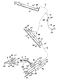
図4はシート後処理装置FSのステープル処理部及び二つ折り処理部を示す断面図である。
【0049】
ステープル手段50及び端綴じストッパ51、中綴じ用の可動ストッパ部材(以下、中綴じストッパと称す)53は綴じ部ユニットUに形成されて、シート後処理装置FSの前面側に引き出し可能になっている。
【0050】
ステープル手段50は、上部機構と下部機構との2分割構造に構成され、その中間に、シートSが通過可能な通路52を形成している。
【0051】
中綴じモードに設定されると、ステープル手段50のステープル処理位置近傍の端綴じストッパ51が搬送路から待避し、ほぼ同時にそれより下流の中綴じストッパ53が起動して通路52を遮断する。
【0052】
中綴じストッパ53は、表紙K及び記録紙Sのサイズ(搬送方向の長さ)が設定又は検知されると、所定位置に移動して停止する。
【0053】
表紙Kが中間スタッカ35上の所定位置に載置された後、画像形成装置Aから搬出された記録紙Sが、シート後処理装置FSの入口搬送部70から第3搬送路▲3▼を通過して、中間スタッカ35上に載置された表紙Kの上面に順次積載され、記録紙Sの先端部が中綴じストッパ53に当接して位置決めされる。
【0054】
最終の記録紙Sが中間スタッカ35上に位置決め載置された後、表紙Kと記録紙Sの全頁とから成るシート束にステープル手段50による中綴じ処理を行う。この中綴じ処理により、表紙K及び記録紙Sの搬送方向の中央部にステープル針が打ち込まれる。
【0055】
(6)第6搬送路▲6▼(二つ折り処理モード)
中綴じ処理後、中綴じストッパ53が揺動して、通路52の下流の通路を開放する。中綴じ処理された表紙Kと記録紙Sから成るシート束は、湾曲した通路61を通過して斜め下方の搬送ベルト62上をガイド板63に案内されて搬送され、更に、ガイド板64上を滑落して、折り部可動ストッパ部材(以下、折り部ストッパと称す)65にシート束の端部が当接して、所定位置に停止する。折り部ストッパ65はシートサイズの設定又は検知結果と駆動手段により所定位置に移動可能である。
【0056】
停止状態のシート束の搬送方向の中央部、即ち中綴じ位置の斜め下方には、突き出しユニット66が設置されている。中綴じ位置の斜め上方には、折りローラ対部67と、二つ折りシート搬送手段68が設置されている。
【0057】
図5は突き出しユニット66、折りローラ対部67、二つ折りシート搬送手段68等から成る折り手段60の断面図である。
【0058】
二つ折り開始信号により可動保持部材662が、固定配置されたガイドバー663に沿って直進し、可動保持部材662に固定された突き出し板661は、シート載置面より上方に突出する。突き出し板661は薄型のナイフ状をなし、その先端部は鋭角をなす。
【0059】
図示の斜め上方に直進して突出した突き出し板661の先端部は、表紙Kと記録紙Sから成るシート束の中央部を押し上げ、シート束を介して折りローラ対部67のニップ部を押し広げて揺動、離間させる。
【0060】
突き出し板661の先端部が前記ニップ部を通過後、突き出し板661が後退して、シート束の中央部は、折りローラ対部67により挟圧されて、折り目が形成される。この折り目は、前述の中綴じ処理によるシート束へのステープル針の打ち込み位置とほぼ一致する。
【0061】
折りローラ対部67の一方の押圧手段67Aは、駆動源に接続して駆動される第1の押圧ローラ671Aと、この第1の押圧ローラ671Aを回転可能に支持し、支軸673Aを中心に揺動可能なアーム672Aと、このアーム672Aの一端に係止され、第1の押圧ローラ671Aをニップ位置方向に付勢するバネ674Aとから成る前段の折り部と、駆動源に接続して駆動される第2の押圧ローラ676Aと、第1の押圧ローラ671Aと同軸上のプーリ675Aと第2の押圧ローラ676Aとの間に巻回された搬送ベルト677Aとから成る後段の折り部とから構成されている。
【0062】
他方の押圧手段67Bも同様な構成をなし、第1の押圧ローラ671B、アーム672B、支軸673B、バネ674B、プーリ675B、第2の押圧ローラ676B、搬送ベルト677Bを有する。なお、第2の押圧ローラ676A,676Bは、第1の押圧ローラ671A,671Bと同様な図示しないアーム、支軸、バネにより揺動可能に支持されている。
【0063】
回転する第1の押圧ローラ671A,671Bにより挟圧されて折り目を形成されたシート束の中央部は、搬送ベルト677A,677Bに挟持されて搬送され、第2の押圧ローラ676A,676Bのニップ位置に送り込まれ、この位置で折り目が更にしっかりされ、二つ折りシート搬送手段68に送り込まれる。
【0064】
二つ折りシート搬送手段68は、シート束を挟圧して搬送する下搬送ベルト681と上搬送ベルト682とから成る。下搬送ベルト681は、駆動ローラ683、従動ローラ685間に張架され、回動可能である。上搬送ベルト682は、駆動ローラ684、従動ローラ686間に張架され、回動可能である。
【0065】
二つ折りシート搬送手段68に送り込まれたシート束は、下搬送ベルト681と上搬送ベルト682との間に挟持されて搬送され、機外の固定排紙皿82上に排出される。
【0066】
図6は表紙Kと記録紙Sの搬送経路と、シート束の中綴じと二つ折り処理過程を示す模式図、図7(a)は中綴じと二つ折りの後処理を施した小冊子の斜視図、図7(b)は後処理済みの小冊子を両開きした状態を示す斜視図である。
【0067】
表紙給紙手段40の給紙皿41上には、表紙Kが第1面(第1頁p1と第8頁p8)を上側にして載置される。給紙皿41から給紙手段により給送された表紙Kは、前記の第4搬送路▲4▼及び第3搬送路▲3▼を通過して搬送され、中間スタッカ35上に、第1面(p1とp8)を下側にして載置される。
【0068】
次に、画像形成装置Aから搬出された画像形成済みの記録紙Sは、第1面(第3頁p3と第6頁p6)を下側にして、シート後処理装置FSに導入される。この記録紙Sは、入口搬送部70から第3搬送路▲3▼に搬送され、中間スタッカ35上に載置された表紙Kの上に、第1面(p3,p6)を下側にして載置される。
【0069】
中間スタッカ35上で、表紙Kと記録紙Sとが整合され、ステープル手段50によりステープル針SPが打ち込まれて中綴じ処理される。
【0070】
中綴じ処理されたシート束は、第5搬送路▲5▼を通過して、ガイド板64及び搬送ベルト62上の所定位置に載置され停止する。このときシート束は、記録紙Sが第1面(p3,p6)を上側に、その上の表紙Kが第1面(p1,p8)を上側になった状態で載置される。
【0071】
次に、突き出しユニット66の押し上げ作動と、折りローラ対部67の駆動回転とにより、二つ折り処理が行われ、引き続き、二つ折りシート搬送手段68により挟持、搬送され、機外の固定排紙皿82上に排出される。
【0072】
中綴じ処理と二つ折り処理により作成された小冊子は、表紙Kの第1面(p1,p8)を外側に向け、その裏面側に第2面(p2,p7)、更にその内側に中身である記録紙Sの第1面(p3,p6)、その内側に記録紙Sの第2面(p4,p5)が配置され、図示のように8頁(p1〜p8)から成る小冊子の頁揃えができる。
【0073】
図8は本発明によるシート後処理装置の制御を示すブロック図である。
【0074】
画像形成装置Aの制御556部において、小冊子作成オートモードを選択、設定し、表紙Kを給紙皿41上に積載し、プリントを開始すると、画像形成装置Aの制御部により、前記の画像プロセスが実行され、画像を担持した記録紙Sはシート後処理装置FSにより、中綴じ処理と二つ折り処理とが行われて、連続して小冊子が作成、排出される。
【0075】
シート後処理装置FSの操作部において、小冊子作成マニュアルモードを選択、設定し、給紙皿41上に、表紙Kとその下に画像形成済みの1冊分の記録紙Sとを積載し、送り出し動作を開始すると、シート後処理装置FSの制御部により、表紙Kと記録紙Sはシート後処理装置FSにより、中綴じ処理と二つ折り処理とが行われて、1冊分の小冊子が作成、排出される。
【0076】
図9は、シート後処理装置のステープル処理部の断面図、図10は図9におけるステープル処理部のA矢視平面図である。
【0077】
ステープル処理部は、上部機構50Aと下部機構50Bとに分割されたステープル手段50と、端綴じストッパ51と中綴じストッパ53とを駆動する駆動手段とを有する。
【0078】
ステープル手段50は、シート搬送方向に直交する方向に2組配置され、図示しない駆動手段により、シート搬送方向に直交する方向に移動可能である。このステープル手段50により、シート幅方向の中央振り分け2箇所、又はシートサイズに対応して角部1箇所にステープル針を打つ。
【0079】
端綴じストッパ51は、ステープル手段50の上部機構50Aに支持されて、シート搬送方向に直交する方向に一体に移動する。
【0080】
端綴じストッパ51の一方の先端部はシート先端突き当て面51Aであり、他方の先端部はステープル手段50の上部機構50Aに支持された支軸501に嵌合して揺動可能に支持されている。
【0081】
支軸501には、捩りバネ502が巻回されていて、端綴じストッパ51のシート先端突き当て面51A側を通路52側にバネ付勢し、端綴じ処理時にシート停止位置に停止させる。
【0082】
前記の2組のステープル手段50の中間部には、綴じ部ユニットUの枠体に固定された支持板503が配置されている。この支持板503の一端に支持された支軸504には、解除レバー54が揺動可能に支持されている。
【0083】
解除レバー54の一方のレバー部54Aには、後述の中綴じストッパユニット55の押圧軸体552が接離可能に当接する。解除レバー54の他方のレバー部54Bは、端綴じストッパ51のシート先端突き当て面51Aの基部を押圧して所定の停止位置に下降させる。
【0084】
支軸504に巻回された捩りバネ505は、解除レバー54を付勢して揺動させ、上方の待避停止位置に停止させる。
【0085】
通路52の上方に固設された前記支持板503に両端支持された2本のガイドバー506は、中綴じストッパユニット55を直線移動させる。
【0086】
中綴じストッパユニット55の枠体551は、前記2本のガイドバー506に摺動する軸受け部と、枠体551の一方の端部に突出した検出部556とを有する。
【0087】
枠体551の一方の端部の近傍には押圧軸体552が固定され、他方の端部には支軸553が固定されている。中綴じストッパ53はこの支軸553に嵌合して揺動する。支軸553には捩りバネ531が巻回されていて、中綴じストッパ53を通路52から上方に待避する方向に付勢している。
【0088】
中綴じストッパ53の下端部は、中綴じ処理時にシート先端部に当接してシート束の位置決めを行うストッパ面部53Aである。中綴じストッパ53の上端部は、後述の偏芯カム555のカム面に当接するカムフォロワ面部である。支軸553に巻回された捩りバネ531は、中綴じストッパ53を偏芯カム555のカム面に押圧、付勢している。
【0089】
図11(a)は、中綴じストッパユニット55の駆動系を示す平面図、図11(b)は、中綴じストッパユニット55の駆動系の正面図である。
【0090】
枠体551に固設されたモータM1の駆動軸に固定されたギアG1は、枠体551に回転可能に支持されたカム軸554の一端に固定されたギアG2に噛合している。カム軸554の他端には、偏芯カム555とホームポジション検出部556とが一体に形成されて固定されている。
【0091】
ホームポジション検出部556は、中空円筒面の一部に切り欠き部を設けた形状をなし、フォトセンサPS3による切り欠き部検出により、中綴じストッパ53のホームポジションを補正する。
【0092】
枠体551の側面には、タイミングベルト557が図示しない係止部材により係止されている。タイミングベルト557を巻回するタイミングプーリ558は、駆動源のモータM2からギア列等の駆動伝達系を介して回転される。
【0093】
図12は、端綴じストッパ51と中綴じストッパ53との連動機構を示す正面図である。
【0094】
図12(a)は中綴じ処理時を示す正面図である。中綴じ処理時には、中綴じストッパユニット55は、前記の図示しない駆動源、タイミングプーリ558、タイミングベルト557等から成る駆動機構により、シートサイズに対応したシート搬送方向の所定位置に移動して停止する。
【0095】
この停止位置において、中綴じストッパ53はモータM1により駆動されて揺動し、図示の停止状態に保持され、シートの先端揃えを可能にする。中綴じ処理後には、中綴じストッパ53はモータM1の逆転駆動により揺動され、図示の波線位置に待避する。
【0096】
また、この中綴じ処理の停止位置において、端綴じストッパ51は、捩りバネ502により付勢されて支軸501を中心にして図示の反時計方向に付勢されているが、この捩りバネ502の付勢力より強い付勢力を有する捩りバネ505に付勢された解除レバー54により、レバー部54Bが係止部51Bを押圧して、端綴じストッパ51を揺動して所定の待避位置に停止させる。なお、解除レバー54は、捩りバネ505により付勢されて支軸504を中心にして図示の時計方向に揺動されて、端綴じストッパ51の係止部51Bに圧接する。
【0097】
図12(b)は端綴じ処理時を示す。端綴じ処理時には、中綴じストッパユニット55は、前記の駆動機構によりガイドバー506に沿って移動して停止する。即ち、移動する中綴じストッパユニット55のホームポジション検出部556がフォトセンサPS2の検出位置に近接すると、押圧軸体552が解除レバー54の一方のレバー部54Aに当接する。
【0098】
中綴じストッパユニット55が、捩りバネ505のトルクに打ち勝って更に前進して、レバー部54Aを押し続けて揺動させると、他方のレバー部54Bも同様に揺動して、端綴じストッパ51の上端部を押圧して押し下げる。この押し下げ動作により、上方の待避位置にあった端綴じストッパ51は、支軸501を中心にして図示の反時計方向に揺動され、シート先端突き当て面51Aは所定の端綴じ処理のシート揃え位置に停止する。
【0099】
なお、解除レバー54の捩りバネ505のトルクは、端綴じストッパ51の捩りバネ502のトルクより大きく設定してあるから、解除レバー54の捩りバネ505は捩りバネ502の付勢力に打ち勝って、端綴じストッパ51を上方の待避位置に持ち上げている。
【0100】
上述のように、中綴じストッパユニット55の移動方向により、中綴じ処理のシート停止と、端綴じ処理のシート停止とを選択させることにより、駆動機構が簡単かつ確実になる。
【0101】
図12(c)は、シートSの端面近傍で中央振り分け2箇所にステープル針SPを打針する端綴じ処理を示す平面図である。
【0102】
図12(d)は、シートSのコーナ部近傍の1箇所にステープル針SPを打針する端綴じ処理を示す平面図である。
【0103】
図12(e)は、シートSの折り目に沿って中央振り分け2箇所にステープル針SPを打針する中綴じ処理を示す平面図である。
【0104】
次に、中綴じストッパ53と端綴じストッパ51の連動機構における駆動源のの初期化について説明する。
【0105】
図10は、シート搬送方向に直交する方向に平行配列された2組のステープル手段50Aがシートの中央振り分け2箇所に中綴じ処理する状態を示す平面図である。
【0106】
シート後処理装置FSに電源が投入されたときには、先ず、図11に示すモータM1は駆動開始して、ホームポジション検出部556を回転させ、フォトセンサPS3により検出することにより、中綴じストッパ53のホームポジションを補正し停止する。
【0107】
次に、図11に示す中綴じストッパユニット55をモータM2により駆動して、端綴じストッパ51側に移動させ(図12(a)の一点鎖線方向)、押圧軸体552が解除レバー54のレバー部54Aを押圧し、レバー部54Bを下げ、枠体551の先端部のホームポジション検出部556をフォトセンサPS2の検出位置に移動させ、中綴じストッパユニット55のホームポジション検出を行い、中綴じストッパユニット55の初期化を行う。
【0108】
上記の中綴じストッパユニット55の移動による初期化後に、端綴じストッパ51を取り付けているステープル手段50の初期化を行う。
【0109】
図9,図10において、ステープル手段50の下部機構50Bの底板500の先端部には検出部50aが突出している。この検出部50aは綴じ部ユニットUに固設されたフォトセンサPS4により位置検出され、ステープル手段50のホームポジション検出を行う。
【0110】
シート後処理装置FSに電源が投入され、中綴じストッパユニット55の初期化後に、ホームポジション外に位置していたステープル手段50はモータM4、駆動伝達系、タイミングベルト509等を経て、シート搬送方向と直交する方向に移動し、ホームポジションにおいて停止する。
【0111】
このホームポジションにおいて、端綴じストッパ51は、初期化後に解除レバー54により押圧されて移動し所定の位置に停止し、通路52を遮断して端綴じ処理を可能にする。
【0112】
もし、初期化の順番が上記と逆で、最初にステープル手段50のホームポジションへの移動が行われ、その後に、中綴じストッパユニット55のホームポジションへの移動が行われると、万一、中綴じストッパユニット55がホームポジションから動いていたら、解除レバー54のレバー部54Bとステープル手段50に装着された端綴じストッパ51の係止部51Bとの係合が外れて干渉を起こす恐れがある。
【0113】
図13(a)〜(d)は中綴じ処理及び折り処理の過程を示す模式図である。
【0114】
図13(a)は中間スタッカ35上に載置され、中綴じストッパ53により端揃えされ、中綴じ処理された複数枚のシートS1,S2の平面図、図13(b)は中綴じ処理されたシートS1,S2の正面図、図13(c)は中折り処理されたシートS1,S2の正面図である。図14はシート後処理装置FSの制御を示すブロック図である。
【0115】
画像形成装置Aからシート後処理装置FSに送り込まれた複数枚のシートは、図2に示す入口搬送部70の受け入れ部71の近傍に設置されたシート通過センサPS1によりシート先端通過及び後端通過が検知される。
【0116】
制御手段90においては、シート通過センサPS1によるシート先端及び後端通過検知信号とタイマとにより、通過するシート1枚毎のシート搬送方向長さ(シートサイズ)を計測する。制御手段90では、1小冊子分の各シートのシートサイズを総て計測した後、最小サイズLを設定する。
【0117】
次に、制御手段90は上記の最小サイズLの設定値に基づき、ステープル処理位置(ステープル針SPの打ち込み位置)が、最小サイズLの二分の一(L/2)になるような先端揃えを行うように、中綴じストッパ53を移動させて位置決め設定する。
【0118】
また、制御手段90は、図4及び図5に示す折り手段60の折り部ストッパ65を、シート先端と折り目との長さが前記のL/2と等しくなるような位置に移動させて設置する。
【0119】
中折り処理後には、小冊子の端部は、最小サイズのシートの先端に揃えられ、最小サイズより長いシートは耳部aとなって突出する。この耳部aは、最小サイズのシートの二つ折り後の揃えられた短い先端側を基準にして断裁する。断裁後のシートから成る小冊子は、シートサイズの大小に係わらず、総て最小限の裁ち落とし寸法で、容易かつ一様にシート端部が揃えられる(図13(d)参照)。
【0120】
なお、シート束の整合不揃いや、分厚いシート束の末端不揃い等を考慮して、裁断寸法を前記のL/2より若干短い(1〜2mm)寸法に設定してもよい。
【0121】
図4、図5に示す折り手段60の折り部ストッパ65を保持する保持部材651は、ガイドバー652に案内されて直線移動可能である。補助部材651は図示しないタイミングベルト、駆動伝達系及びモータM4により移動される。
【0122】
モータM4はステッピングモータから成る。シート後処理装置FS内に送り込まれるシートのサイズ(シートの搬送方向の長さ)が検知されると、モータM4が駆動されて、折り部ストッパ65がシートサイズに対応した所定位置に移動され停止する。この停止状態の折り部ストッパ65に、中綴じ処理されたシート束が傾斜配置されたガイド板64上を滑走して衝突する。
【0123】
折り部ストッパ65は、折り手段60のガイド板(スタック台)64上に搬送される中綴じ処理されたシート束をシートサイズに対応してシート搬送方向の所定位置に移動してシート先端を位置決めする折り手段用の可動ストッパ部材であり、モータ(ステッピングモータ)M4、ステッピングモータ駆動手段、制御手段90等により駆動される。
【0124】
傾斜配置されたガイド板64の底部には、折り部ストッパ65へのシート束の進入を検知する検知手段が配置されている。検知手段はアクチュエータ653とフォトセンサPS5とから成る。アクチュエータ653はガイド板64に揺動可能に支持され、ガイド板64上を滑落するシートSの進行方向先端部に当接して揺動することにより、フォトセンサPS5の検出光路を断続して、シートSの先端部通過を検出する。
【0125】
制御手段90のステッピングモータ駆動手段は、フォトセンサPS5によるシートSの先端部通過検知信号により、シート束の先端部が折り部ストッパ65に当接する直前にステッピングモータM4の回転を阻止させるように制御する。
【0126】
中綴じ処理された分厚いシート束が、ガイド板64の面上を高速で滑走して、折り部ストッパ65に衝突する場合にも、折り部ストッパ65は、ステッピングモータM4により電気的に固定されているから、この衝突時の衝撃に耐えて所定位置から移動することはない。従って、中折り処理が正確な位置で行われる。
【0127】
なお、本発明の実施の形態では、複写機に接続したシート後処理装置を示したが、プリンタ、ファクシミリ等の画像形成装置や軽印刷機等と接続して使用するシート後処理装置にも適用可能である。
【0128】
【発明の効果】
本発明のシート後処理装置の請求項1、2により、中綴じストッパの移動に連動して、端綴じストッパが作用位置と待避位置を占める構成にしたことにより、1つの駆動源と簡単な駆動手段により確実に両ストッパを駆動することができる。
【0129】
請求項3により、シート搬送方向に移動する中綴じストッパユニットと、シート搬送方向と直交する方向に移動可能なステープル手段に装着された昇降作動する端綴じストッパとが端綴じ処理時に干渉して発生する誤作動や故障発生が防止される。
【0130】
請求項4により、シートの搬送方向の規定長さにばらつきのある場合にも、中綴じの位置及び端綴じの位置を正確に微調整して後処理することができる。
【0131】
請求項5により、シートの搬送方向の規定長さにばらつきのある場合、シートの最小長さを計測、選択して、シート中綴じの位置及び端綴じの位置を微調整して後処理し、二つ折り処理された小冊子の端部を容易に断裁することにより、出来上がり小冊子の品質の向上が達成される。
【0132】
請求項6,7により、中綴じ処理されたシート束の先端部を、折り手段の移動可能なシート先端部突き当て用のストッパに突き当てるとき、シート束先端部との衝撃によってストッパが移動して、二つ折り位置がずれることが防止されるから、正確な位置に折り処理が行われる。
【0133】
請求項8により、複写機、プリンタ、ファクシミリ等の画像形成装置により所望のデジタル処理が行われ、排出された記録紙は、シート後処理装置において、端綴じ、中綴じ、折り等の処理モードが頁揃えされて正しい位置に行われる。
【図面の簡単な説明】
【図1】シート後処理装置と自動原稿送り装置とを備えた画像形成装置の全体構成図。
【図2】シート後処理装置のシート搬送経路を示す模式図。
【図3】シート後処理装置の上部機構を示す断面図。
【図4】シート後処理装置のステープル処理部及び二つ折り処理部を示す断面図。
【図5】突き出しユニット、折りローラ対部、二つ折りシート搬送手段の断面図。
【図6】表紙と記録紙の搬送経路と、シート束の中綴じと二つ折り処理過程を示す模式図。
【図7】中綴じと二つ折りの後処理を施した小冊子の斜視図及び後処理済みの小冊子を両開きした状態を示す斜視図。
【図8】シート後処理装置の制御を示すブロック図。
【図9】シート後処理装置のステープル処理部の断面図。
【図10】図9におけるステープル処理部のA矢視平面図。
【図11】中綴じストッパユニットの駆動系を示す平面図、及び正面図
【図12】中綴じ処理ユニットと端綴じストッパの中綴じ処理時及び端綴じ処理時の正面図、及びシートのステープル処理位置とストッパ位置とを示す平面図。
【図13】中綴じ処理及び折り処理の過程を示す模式図。
【図14】シート後処理装置の制御を示すブロック図。
【符号の説明】
10 固定排紙皿
20 シフト処理搬送部(大容量排紙搬送路)
30 中間載置手段(スタック手段)
35 中間スタッカ
40 表紙給紙手段
50 ステープル手段
51 端綴じ用可動ストッパ部材(端綴じストッパ)
53 中綴じ用可動ストッパ部材(中綴じストッパ)
54 解除レバー
55 中綴じストッパユニット
60 折り手段
62 搬送ベルト
63 ガイド板
64 ガイド板(スタック台)
65 折り部可動ストッパ部材(折り部ストッパ)
653 アクチュエータ
66 突き出しユニット
67 折りローラ対部
70 入口搬送部(搬送手段)
71 受け入れ部
72 入口部ローラ対
81 可動排紙皿
82 固定排紙皿
90 制御手段
A 画像形成装置
FS シート後処理装置(フィニッシャ)
K 表紙(カバーシート)
M1,M2,M3,M4 モータ(ステッピングモータ)
PS1 シート通過センサ
PS2,PS3,PS4,PS5 フォトセンサ
S 記録紙
S1,S2 シート
SP ステープル針[0001]
BACKGROUND OF THE INVENTION
In the present invention, sheets discharged after image formation from an image forming apparatus such as an electrophotographic copying machine, a printer, and a facsimile are sequentially taken into a sheet post-processing apparatus, and post-processing such as binding (stapling) and folding is performed on the sheet. The present invention relates to a sheet post-processing apparatus having a function of performing and discharging to a paper discharge unit.
[0002]
[Prior art]
A sheet post-processing device called a finisher is used as a device that collates a plurality of image-recorded recording sheets discharged from the image forming apparatus for each number of copies and binds them with staples.
[0003]
This finisher is connected to a main body of an image forming apparatus such as a copying machine or a printer, and is driven in response to a sequence operation of a copy or print process.
[0004]
Therefore, for an image forming apparatus capable of processing an image forming process at high speed, a finisher capable of high speed processing capable of performing a function following the processing speed is required.
[0005]
With regard to such a finisher, JP-A-60-142359, JP-A-60-158463, JP-A-62-239169, JP-A-62-228802, JP-A-63-267667, JP-A-2-276661, It is disclosed in Japanese Laid-Open Patent Publication Nos. 8-319054 and 5-41991.
[0006]
A bookbinding apparatus disclosed in Japanese Patent Application Laid-Open No. 60-183459 includes a cover sheet supply device, and performs bookbinding finishing operations such as punching or stapling after the copy paper group and the cover sheet are overlapped.
[0007]
JP-A-6-72064, JP-A-7-187479, and JP-A-8-192951 are sheet post-processing apparatuses having a saddle stitching processing function.
[0008]
A paper processing apparatus disclosed in Japanese Patent Laid-Open No. 10-148983 is a paper processing apparatus having a paper folding means for folding a paper sheet in half.
[0009]
[Problems to be solved by the invention]
(1) A conventional sheet post-processing apparatus is provided with a drive source (motor or the like) for a movable stopper member for a saddle stitching mode and a drive source (motor or the like) for a movable stopper member for saddle stitching. Therefore, the manufacturing cost is increased.
[0010]
(2) When a stepping motor is used as a drive source, a phase shift may occur due to an external force. Therefore, an initialization operation for positioning the drive startable position must be performed prior to the start of drive. When other parts are operated in conjunction with the operation of a certain part, it is necessary to limit the order of each initialization operation. If the order is incorrect, interference occurs between the operating members, resulting in failure of the apparatus. In order to prevent this, there is a drawback that the drive system of the apparatus becomes complicated.
[0011]
(3) The length of the sheet in the conveyance direction varies depending on environmental humidity, cutting accuracy, single-sided or double-sided recording, and the like. When the leading edge alignment is performed with reference to the leading edge of the sheet having the difference in length, and then saddle stitching and folding are performed, the trailing edge becomes uneven due to the difference in sheet length. When cutting the rear end irregular part of the sheet bundle that has been folded in half with a cutter or the like, if the sheet is cut by looking at the end of the outermost sheet, the sheet with a short overall length is inside the sheet bundle. However, the irregularity remains and the finished appearance of the sheet bundle is impaired.
[0012]
(4) A stepping motor is used as the drive source when the movable stopper member for folding is moved in accordance with the sheet size and stopped at a predetermined position to position the leading end of the sheet bundle being conveyed. In this case, the movable stopper member moves due to an impact force with the leading end portion of the sheet bundle conveyed. If the movable stopper member moves and deviates from the predetermined position, the bi-fold position at the center of the sheet is deviated, the leading end and the trailing end of the sheet bundle do not match, and the finished appearance of the sheet bundle is impaired.
[0013]
[Means for Solving the Problems]
The present invention has been made to solve the above-described problems in the saddle stitching and bi-folding process, and provides a sheet post-processing apparatus having the following means.
[0014]
(1) Conveying means for sequentially receiving and conveying the image-formed sheets carried out from the image forming apparatus, stacking means for positioning and stacking the received sheets, and staples for binding the sheets stacked on the stack means In the sheet post-processing apparatus having the means, both the end binding process for binding one end of the sheet and the saddle stitching process for binding the central part in the conveyance direction of the sheet can be performed, and the sheet can pass therethrough. And a stapling unit movable stopper member that moves to a predetermined position in the sheet conveying direction in accordance with the sheet size of the sheet placed on the stack unit and positions the sheet end portion. In conjunction with the movement of the movable binding member for saddle stitching processing, the sheet conveying path is blocked and the sheet edge is positioned. And a movable stopper member for end-stitching processing that enables the end-stitching processing and allows a sheet to be saddle-stitched while being retracted from the sheet conveyance path, and a sheet post-processing Apparatus (claim 1).
[0015]
(2) Conveying means for sequentially receiving and conveying image-formed sheets carried out from the image forming apparatus, stacking means for positioning and stacking the received sheets, and staples for binding sheets stacked on the stacking means In the sheet post-processing apparatus having the means, both the end binding process for binding one end of the sheet and the saddle stitching process for binding the central part in the conveyance direction of the sheet can be performed, and the sheet can pass therethrough. And a stapling unit movable stopper member that moves to a predetermined position in the sheet conveying direction in accordance with the sheet size of the sheet placed on the stack unit and positions the sheet end portion. In conjunction with the movement of the movable binding member for saddle stitching processing, the sheet conveying path is blocked and the sheet edge is positioned. An end-stitching process movable stopper member that enables the end-stitching process and allows a sheet to be saddle-stitched by being retracted from the sheet conveyance path. When the member is located at the home position, the movable binding member for the end binding process is set to the sheet leading end positioning position that blocks the sheet conveyance path, and when the power is turned on to the sheet post-processing apparatus A sheet post-processing apparatus that initializes a stop position of the stapling means after an initialization operation of the saddle stitching stopper unit.
(Claim 3).
[0016]
(3) Conveying means for sequentially receiving and conveying the image-formed sheets carried out from the image forming apparatus, stacking means for positioning and stacking the received sheets, and staples for binding the sheets stacked on the stacking means In the sheet post-processing apparatus having the means, both the end binding process for binding one end of the sheet and the saddle stitching process for binding the central part in the conveyance direction of the sheet can be performed, and the sheet can pass therethrough. And a stapling unit movable stopper member that moves to a predetermined position in the sheet conveying direction in accordance with the sheet size of the sheet placed on the stack unit and positions the sheet end portion. In conjunction with the movement of the movable binding member for saddle stitching processing, the sheet conveying path is blocked and the sheet edge is positioned. The edge-binding processing movable stopper member that allows the sheet to be saddle-stitched while being retracted from the sheet conveyance path, and the sheet that is carried into the sheet post-processing device. A sheet post-processing apparatus, comprising: a sheet positioning unit that makes it possible to adjust the position of the movable stopper member for saddle stitching processing according to the length in the conveying direction.
[0017]
(4) Conveying means for sequentially receiving and conveying image-formed sheets carried out from the image forming apparatus, stacking means for positioning and stacking the received sheets, and staples for binding the sheets stacked on the stack means And a folding means for folding the sheet in half, an end binding process for binding one end of the sheet, and a saddle stitching process for binding a central portion in the conveyance direction of the sheet The stapler is configured to be divided so that the sheet can pass through, and the sheet is moved to a predetermined position in the sheet conveyance direction corresponding to the sheet size of the sheet placed on the stacker. A movable stopper member for saddle stitching processing for positioning the sheet end portion and a movement of the movable stopper member for saddle stitching processing are linked to the movement. Then, the sheet feeding path is blocked and the sheet edge is positioned to enable the end binding process, and the end binding process movable stopper that allows the sheet to be saddle stitched while being retracted from the sheet feeding path is allowed to pass. A movable stopper member for folding means for positioning a sheet leading end by moving a member conveyed on a stacking base of the folding means to a predetermined position in the sheet conveying direction corresponding to the sheet size, and the sheet post-processing Measuring means for measuring the length of the sheet carried in the apparatus in the conveying direction, and a sheet positioning means for the saddle stitching movable stopper member and a sheet positioning means for the movable stopper member for the folding means, During the sheet post-processing operation to create one booklet, based on the measured value of the sheet length in the sheet conveying direction by the measuring means, the minimum in the sheet conveying direction Sheet post-processing apparatus, characterized in that the stop position in the criterion is determined is (claim 5).
[0018]
(5) Conveying means for sequentially receiving and conveying image-formed sheets carried out from the image forming apparatus, stacking means for positioning and stacking the received sheets, and staples for binding the sheets stacked on the stack means In the sheet post-processing apparatus, the sheet post-processing apparatus includes: a folding unit configured to position and place the stapled sheet on the sheet placing table and to fold the sheet in half. A movable stopper member for folding means for moving the sheet to a predetermined position in the sheet conveying direction corresponding to the sheet size to position the leading end of the sheet, a stepping motor driving means for movably driving the movable stopper member, Control means for controlling stepping motor drive means, and movable stopper member for the folding means Detecting means for detecting the entrance of the sheet, and controlling the stepping motor driving means by a detection signal of the detecting means, so that the stepping motor driving means immediately before the leading end of the sheet comes into contact with the movable stopper member The sheet post-processing apparatus is characterized in that the rotation of the sheet is stopped and fixed (claim 6).
[0019]
(6) An image forming apparatus comprising the sheet post-processing apparatus according to any one of
[0020]
DETAILED DESCRIPTION OF THE INVENTION
Next, an embodiment of the sheet post-processing apparatus of the present invention will be described with reference to the accompanying drawings.
[0021]
FIG. 1 is an overall configuration diagram of an image forming apparatus A including a sheet post-processing device (finisher) FS and an automatic document feeder DF.
[0022]
The illustrated image forming apparatus A includes an
An automatic document feeder DF is mounted on the upper part of the image forming apparatus A. A sheet post-processing device (finisher) FS is connected to the left side of the image forming apparatus A shown in the drawing on the
[0023]
The document d placed on the document table of the automatic document feeder DF is conveyed in the direction of the arrow, and an image on one or both sides of the document is read by the optical system of the image reading unit (scanning exposure device) 1, and a CCD image sensor. 1A is read.
[0024]
The analog signal photoelectrically converted by the
[0025]
In the
[0026]
The sheet post-processing apparatus FS includes a fixed
[0027]
An
[0028]
FIG. 2 is a schematic diagram illustrating a sheet conveyance path of the sheet post-processing apparatus FS, and FIG. 3 is a cross-sectional view illustrating an upper mechanism of the sheet post-processing apparatus FS.
[0029]
The sheet post-processing device FS is installed with its position and height adjusted so that the receiving
[0030]
The conveyance path of the recording sheet S connected downstream of the sheet conveyance of the
[0031]
(1) First transport path {circle around (1)} (non-staple, non-sort mode, discharged to the fixed
The image-formed recording sheet S discharged from the image forming apparatus A is introduced into the receiving
[0032]
In this sheet conveyance process, the switching gate G1 is swung by the drive of the solenoid SD1 to close the
[0033]
The fixed
[0034]
(2) Second transport path {circle around (2)} (offset mode or non-sort mode, discharged to the movable discharge tray 81)
When this transport mode is set, the switching gate G1 closes the
[0035]
The image-formed recording sheet S discharged from the image forming apparatus A passes through the receiving
[0036]
The movable
[0037]
(3) Third conveyance path {circle around (3)} (edge binding mode, paper discharged to the movable paper discharge tray 81)
The image-formed recording sheet S that has been subjected to image formation processing in the image forming apparatus A and sent to the receiving
[0038]
When the large recording paper S larger than A4 and B5 size is transported in the third transport path (3), the solenoid SD2 is driven, and the recording paper S passes through the
[0039]
In the third transport path (3), in order to improve the copy productivity by transporting a small-sized recording paper S such as A4, B5 size, etc. continuously and efficiently, the
[0040]
When the solenoid SD2 for the switching gate G2 and the solenoid SD3 for the switching gate G3 are driven together, the leading ends of the switching gates G2 and G3 both swing counterclockwise as shown in the figure, and the
[0041]
Next, the energization of the solenoid SD3 is turned off, the tip of the switching gate G3 is swung clockwise, the passage 31B is closed, and the
[0042]
At a predetermined timing, the conveying
[0043]
[0044]
A cutout portion is formed in a part of the sheet stacking surface of the
[0045]
(4) Fourth transport path (4) (cover paper feed mode)
The cover sheet feeding means 40 is composed of a cover sheet placing portion comprising a
[0046]
One cover sheet (cover sheet) K fed from the cover sheet feeding means 40 passes through the
[0047]
The conveying
[0048]
(5) Fifth transport path <5> (saddle stitching mode)
FIG. 4 is a cross-sectional view showing the staple processing unit and the two-fold processing unit of the sheet post-processing apparatus FS.
[0049]
A stapling means 50, an
[0050]
The stapling means 50 is configured in a two-part structure of an upper mechanism and a lower mechanism, and a
[0051]
When the saddle stitching mode is set, the
[0052]
The
[0053]
After the cover sheet K is placed at a predetermined position on the
[0054]
After the final recording paper S is positioned and placed on the
[0055]
(6) Sixth transport path {circle around (6)} (bi-fold processing mode)
After the saddle stitching process, the
[0056]
A protruding
[0057]
FIG. 5 is a cross-sectional view of the folding means 60 including the
[0058]
The
[0059]
The leading end portion of the protruding plate 661 that protrudes straightly upward as shown in the figure pushes up the center portion of the sheet bundle composed of the cover sheet K and the recording sheet S, and pushes the nip portion of the
[0060]
After the leading end of the protruding plate 661 passes through the nip portion, the protruding plate 661 moves backward, and the central portion of the sheet bundle is pinched by the
[0061]
One
[0062]
The other
[0063]
The central portion of the sheet bundle formed with a fold by being pressed by the rotating first
[0064]
The double-folded
[0065]
The sheet bundle fed into the folded sheet conveying means 68 is nipped between the lower conveying
[0066]
FIG. 6 is a schematic diagram illustrating the conveyance path of the cover sheet K and the recording sheet S, the saddle stitching and folding process of the sheet bundle, and FIG. 7A is a perspective view of the booklet that has been subjected to the saddle stitching and folding process. FIG. 7B is a perspective view showing a state in which the post-processed booklet is double-opened.
[0067]
On the
[0068]
Next, the image-formed recording sheet S carried out from the image forming apparatus A is introduced into the sheet post-processing apparatus FS with the first side (the third page p3 and the sixth page p6) facing down. This recording sheet S is transported from the
[0069]
The cover sheet K and the recording sheet S are aligned on the
[0070]
The sheet bundle subjected to the saddle stitching process passes through the fifth conveyance path (5), is placed at a predetermined position on the
[0071]
Next, the folding operation is performed by the push-up operation of the
[0072]
The booklet created by the saddle stitching process and the half-folding process has the first side (p1, p8) of the cover K facing outward, the second side (p2, p7) on the back side, and the contents inside the booklet. The first side (p3, p6) of the recording paper S and the second side (p4, p5) of the recording paper S are arranged on the inside thereof, and the page alignment of the booklet consisting of 8 pages (p1 to p8) as shown in the figure. it can.
[0073]
FIG. 8 is a block diagram showing the control of the sheet post-processing apparatus according to the present invention.
[0074]
In the
[0075]
In the operation section of the sheet post-processing apparatus FS, the booklet creation manual mode is selected and set, and the cover sheet K and an image-formed recording sheet S are stacked on the
[0076]
9 is a cross-sectional view of the staple processing unit of the sheet post-processing apparatus, and FIG. 10 is a plan view of the staple processing unit in FIG.
[0077]
The staple processing unit includes a
[0078]
Two sets of stapling means 50 are arranged in a direction orthogonal to the sheet conveying direction, and can be moved in a direction orthogonal to the sheet conveying direction by a driving means (not shown). With this stapling means 50, staples are placed at two central sorting positions in the sheet width direction or at one corner portion corresponding to the sheet size.
[0079]
The
[0080]
One end of the
[0081]
A
[0082]
A
[0083]
A
[0084]
The
[0085]
Two guide bars 506 supported at both ends by the
[0086]
The
[0087]
A
[0088]
A lower end portion of the
[0089]
FIG. 11A is a plan view showing a drive system of the saddle
[0090]
The gear G1 fixed to the drive shaft of the motor M1 fixed to the
[0091]
The home
[0092]
A
[0093]
FIG. 12 is a front view showing an interlocking mechanism between the
[0094]
FIG. 12A is a front view showing the saddle stitching process. During the saddle stitching process, the saddle
[0095]
At this stop position, the
[0096]
In the saddle stitching processing stop position, the
[0097]
FIG. 12B shows the end binding process. During the end binding process, the saddle
[0098]
When the saddle
[0099]
Since the torque of the
[0100]
As described above, by selecting the sheet stop for the saddle stitching process and the sheet stop for the end stitching process according to the moving direction of the saddle
[0101]
FIG. 12C is a plan view showing an end binding process in which staple needles SP are hit at two central sorting positions in the vicinity of the end surface of the sheet S. FIG.
[0102]
FIG. 12D is a plan view showing an end binding process in which the staple needle SP is driven at one place in the vicinity of the corner portion of the sheet S.
[0103]
FIG. 12E is a plan view showing a saddle stitching process in which staple needles SP are hit at two centrally distributed locations along the crease of the sheet S. FIG.
[0104]
Next, initialization of the drive source in the interlocking mechanism of the
[0105]
FIG. 10 is a plan view showing a state in which the two sets of stapling means 50A arranged in parallel in the direction orthogonal to the sheet conveying direction perform the saddle stitching process at two centrally distributed portions of the sheet.
[0106]
When the power is supplied to the sheet post-processing apparatus FS, first, the motor M1 shown in FIG. 11 starts to drive, rotates the home
[0107]
Next, the saddle
[0108]
After initialization by the movement of the saddle
[0109]
9 and 10, a
[0110]
After the sheet post-processing apparatus FS is turned on and the saddle
[0111]
In this home position, the
[0112]
If the initialization order is the reverse of the above, the staple means 50 is first moved to the home position, and then the saddle
[0113]
FIGS. 13A to 13D are schematic views showing the processes of the saddle stitching process and the folding process.
[0114]
13A is a plan view of a plurality of sheets S1 and S2 that are placed on the
[0115]
A plurality of sheets sent from the image forming apparatus A to the sheet post-processing apparatus FS are passed through the leading end and the trailing end of the sheet by the sheet passing sensor PS1 installed in the vicinity of the receiving
[0116]
In the control means 90, the length (sheet size) in the sheet conveyance direction for each passing sheet is measured by a sheet leading edge / rear edge detection signal from the sheet passing sensor PS1 and a timer. The control means 90 sets the minimum size L after measuring all the sheet sizes of each sheet for one booklet.
[0117]
Next, based on the set value of the minimum size L, the
[0118]
Further, the control means 90 is installed by moving the
[0119]
After the half-folding process, the end of the booklet is aligned with the front end of the minimum size sheet, and a sheet longer than the minimum size protrudes as an ear part a. This ear | edge part a is cut | judged on the basis of the short front end side with which the sheet | seat of the minimum size was aligned after folding in half. A booklet composed of sheets after cutting is easily and uniformly aligned with the minimum trimming size regardless of the size of the sheet (see FIG. 13D).
[0120]
In consideration of misalignment of the sheet bundle and uneven end of the thick sheet bundle, the cutting dimension may be set to a dimension slightly shorter (1-2 mm) than L / 2.
[0121]
The holding
[0122]
The motor M4 is a stepping motor. When the size of the sheet fed into the sheet post-processing device FS (the length in the sheet conveyance direction) is detected, the motor M4 is driven, and the
[0123]
The
[0124]
At the bottom of the
[0125]
The stepping motor driving means of the control means 90 is controlled so as to prevent the rotation of the stepping motor M4 immediately before the leading edge of the sheet bundle abuts against the
[0126]
Even when the thick sheet bundle subjected to saddle stitching slides on the surface of the
[0127]
In the embodiment of the present invention, a sheet post-processing apparatus connected to a copying machine is shown. However, the present invention is also applicable to an image forming apparatus such as a printer or a facsimile, or a sheet post-processing apparatus used by connecting to a light printing machine. Is possible.
[0128]
【The invention's effect】
According to
[0129]
According to the third aspect, the saddle stitching stopper unit moving in the sheet conveying direction and the end binding stopper mounted on the stapling means movable in the direction orthogonal to the sheet conveying direction interfere with each other during the end binding process. Malfunctions and failures are prevented.
[0130]
According to the fourth aspect, even when there is a variation in the specified length in the sheet conveyance direction, the saddle stitching position and the edge stitching position can be accurately fine-tuned and post-processed.
[0131]
According to
[0132]
According to
[0133]
According to the eighth aspect, desired digital processing is performed by an image forming apparatus such as a copying machine, a printer, or a facsimile, and the discharged recording paper has processing modes such as edge binding, saddle stitching, and folding in the sheet post-processing apparatus. The pages are aligned and placed in the correct position.
[Brief description of the drawings]
FIG. 1 is an overall configuration diagram of an image forming apparatus including a sheet post-processing apparatus and an automatic document feeder.
FIG. 2 is a schematic diagram illustrating a sheet conveyance path of a sheet post-processing apparatus.
FIG. 3 is a cross-sectional view showing an upper mechanism of a sheet post-processing apparatus.
FIG. 4 is a cross-sectional view illustrating a staple processing unit and a two-fold processing unit of the sheet post-processing apparatus.
FIG. 5 is a cross-sectional view of a protrusion unit, a pair of folding rollers, and a folded sheet conveying unit.
FIG. 6 is a schematic diagram showing a cover and recording sheet conveyance path, a sheet bundle saddle stitching, and a folding process.
FIG. 7 is a perspective view of a booklet that has been subjected to post-processing of saddle stitching and bi-folding, and a perspective view showing a state in which the post-processed booklet is double-opened.
FIG. 8 is a block diagram showing control of the sheet post-processing apparatus.
FIG. 9 is a cross-sectional view of a staple processing unit of the sheet post-processing apparatus.
10 is a plan view of the staple processing unit in FIG.
FIG. 11 is a plan view and a front view showing a drive system of the saddle stitching stopper unit.
FIG. 12 is a front view of the saddle stitching processing unit and the edge stitching stopper during the saddle stitching process and the edge stitching process, and a plan view showing the staple processing position and the stopper position of the sheet.
FIG. 13 is a schematic diagram showing a process of saddle stitching processing and folding processing.
FIG. 14 is a block diagram illustrating control of the sheet post-processing apparatus.
[Explanation of symbols]
10 Fixed paper tray
20 Shift processing transport section (large capacity discharge transport path)
30 Intermediate mounting means (stacking means)
35 Intermediate stacker
40 Cover paper feeding means
50 Staple means
51 Movable stopper member for end binding (end binding stopper)
53 Moveable stopper member for saddle stitching (saddle stitching stopper)
54 Release lever
55 Saddle Stitch Stopper Unit
60 folding means
62 Conveyor belt
63 Guide plate
64 Guide plate (stack base)
65 Folding part movable stopper member (Folding part stopper)
653 Actuator
66 Projection unit
67 Folding roller pair
70 Inlet transport section (transport means)
71 Receiving part
72 Inlet roller pair
81 Movable output tray
82 Fixed paper tray
90 Control means
A Image forming apparatus
FS sheet post-processing equipment (finisher)
K cover (cover sheet)
M1, M2, M3, M4 motor (stepping motor)
PS1 Sheet passing sensor
PS2, PS3, PS4, PS5 Photo sensor
S Recording paper
S1, S2 sheet
SP staple needle
Claims (8)
前記シートの一端を綴じ合わせる端綴じ処理と、前記シートの搬送方向の中央部を綴じ合わせる中綴じ処理との両処理を可能とし、前記シートが通過可能になるように分割構成したステープル手段と、
前記スタック手段上に載置されたシートのシートサイズに対応してシート搬送方向の所定位置に移動してシート端部を位置決めする中綴じ処理用可動ストッパ部材と、
前記中綴じ処理用可動ストッパ部材の移動に連動して、シート搬送路を遮断しシート端部位置決めをして前記端綴じ処理を可能にするとともに、前記シート搬送路から待避して中綴じ処理するシートを通過可能にする端綴じ処理用の可動ストッパ部材と、を有することを特徴とするシート後処理装置。Conveying means for sequentially receiving and conveying the image-formed sheets carried out from the image forming apparatus, stacking means for positioning and stacking the received sheets, and stapling means for binding the sheets stacked on the stacking means In a sheet post-processing apparatus having
A stapler configured to be configured so as to be capable of performing both of an end binding process for binding one end of the sheet and a saddle stitching process for binding a central portion in the conveyance direction of the sheet, and to allow the sheet to pass;
A saddle-stitching movable stopper member that moves to a predetermined position in the sheet conveyance direction in accordance with the sheet size of the sheet placed on the stack means and positions the sheet end portion;
In conjunction with the movement of the movable binding member for saddle stitching processing, the sheet conveying path is blocked and the sheet end portion is positioned to enable the end binding process, and the saddle stitching process is performed while avoiding the sheet conveying path. A sheet post-processing apparatus, comprising: an end-stitching movable stopper member that allows a sheet to pass therethrough.
前記シートの一端を綴じ合わせる端綴じ処理と、前記シートの搬送方向の中央部を綴じ合わせる中綴じ処理との両処理を可能とし、前記シートが通過可能になるように分割構成したステープル手段と、
前記スタック手段上に載置されたシートのシートサイズに対応してシート搬送方向の所定位置に移動してシート端部を位置決めする中綴じ処理用可動ストッパ部材と、
前記中綴じ処理用可動ストッパ部材の移動に連動して、シート搬送路を遮断しシート端部位置決めをして前記端綴じ処理を可能にするとともに、前記シート搬送路から待避して中綴じ処理するシートを通過可能にする端綴じ処理用可動ストッパ部材と、を有し、
前記中綴じ処理用可動ストッパ部材がホームポジションに位置するとき、前記端綴じ処理用の可動ストッパ部材がシート搬送路を遮断するシート先端位置決め位置に設定されるように構成され、
前記シート後処理装置に電源が投入されたとき、前記中綴じストッパユニットの初期化動作の後に、前記ステープル手段の停止位置の初期化を行うことを特徴とするシート後処理装置。Conveying means for sequentially receiving and conveying the image-formed sheets carried out from the image forming apparatus, stacking means for positioning and stacking the received sheets, and stapling means for binding the sheets stacked on the stacking means In a sheet post-processing apparatus having
A stapler configured to be configured so as to be capable of performing both of an end binding process for binding one end of the sheet and a saddle stitching process for binding a central portion in the conveyance direction of the sheet, and to allow the sheet to pass;
A saddle-stitching movable stopper member that moves to a predetermined position in the sheet conveyance direction in accordance with the sheet size of the sheet placed on the stack means and positions the sheet end portion;
In conjunction with the movement of the movable binding member for saddle stitching processing, the sheet conveying path is blocked and the sheet end portion is positioned to enable the end binding process, and the saddle stitching process is performed while avoiding the sheet conveying path. A movable stopper member for end binding processing that allows the sheet to pass through,
When the saddle stitching process movable stopper member is positioned at the home position, the end stitching process movable stopper member is configured to be set at a sheet leading edge positioning position that blocks the sheet conveyance path,
The sheet post-processing apparatus, wherein when the power is supplied to the sheet post-processing apparatus, the stop position of the stapling unit is initialized after the initialization operation of the saddle stitching stopper unit.
前記シートの一端を綴じ合わせる端綴じ処理と、前記シートの搬送方向の中央部を綴じ合わせる中綴じ処理との両処理を可能とし、前記シートが通過可能になるように分割構成したステープル手段と、
前記スタック手段上に載置されたシートのシートサイズに対応してシート搬送方向の所定位置に移動してシート端部を位置決めする中綴じ処理用可動ストッパ部材と、
前記中綴じ処理用可動ストッパ部材の移動に連動して、シート搬送路を遮断しシート端部位置決めをして前記端綴じ処理を可能にするとともに、前記シート搬送路から待避して中綴じ処理するシートを通過可能にする端綴じ処理用可動ストッパ部材と、
前記シート後処理装置に搬入されてくるシートの搬送方向の長さに応じて、前記中綴じ処理用の可動ストッパ部材の位置を調整可能にするシート位置決め手段と、を有することを特徴とするシート後処理装置。Conveying means for sequentially receiving and conveying the image-formed sheets carried out from the image forming apparatus, stacking means for positioning and stacking the received sheets, and stapling means for binding the sheets stacked on the stacking means In a sheet post-processing apparatus having
A stapler configured to be configured so as to be capable of performing both of an end binding process for binding one end of the sheet and a saddle stitching process for binding a central portion in the conveyance direction of the sheet, and to allow the sheet to pass;
A saddle-stitching movable stopper member that moves to a predetermined position in the sheet conveyance direction in accordance with the sheet size of the sheet placed on the stack means and positions the sheet end portion;
In conjunction with the movement of the movable binding member for saddle stitching processing, the sheet conveying path is blocked and the sheet end portion is positioned to enable the end binding process, and the saddle stitching process is performed while avoiding the sheet conveying path. A movable stopper member for end binding processing that allows the sheet to pass through;
A sheet positioning unit that enables adjustment of the position of the movable stopper member for the saddle stitching process according to the length of the sheet carried into the sheet post-processing apparatus in the conveyance direction. Post-processing device.
前記シートの一端を綴じ合わせる端綴じ処理と、前記シートの搬送方向の中央部を綴じ合わせる中綴じ処理との両処理を可能とし、前記シートが通過可能になるように分割構成したステープル手段と、
前記スタック手段上に載置されたシートのシートサイズに対応してシート搬送方向の所定位置に移動してシート端部を位置決めする中綴じ処理用可動ストッパ部材と、
前記中綴じ処理用可動ストッパ部材の移動に連動して、シート搬送路を遮断しシート端部位置決めをして前記端綴じ処理を可能にするとともに、前記シート搬送路から待避して中綴じ処理するシートを通過可能にする端綴じ処理用可動ストッパ部材と、
前記折り手段のスタック台上に搬送されるシートをシートサイズに対応してシート搬送方向の所定位置に移動してシート先端を位置決めする折り手段用の可動ストッパ部材と、
前記シート後処理装置に搬入されてくるシートの搬送方向の長さを計測する計測手段とを有し、
前記中綴じ処理用可動ストッパ部材のシート位置決め手段及び前記折り手段用の可動ストッパ部材のシート位置決め手段は、1冊の小冊子を作成するシート後処理動作中で、前記計測手段によるシート搬送方向のシート長さの計測値に基づき、シート搬送方向の最小長さを基準にして停止位置が決定されることを特徴とするシート後処理装置。Conveying means for sequentially receiving and conveying the image-formed sheets carried out from the image forming apparatus; stacking means for positioning and stacking the received sheets; and stapling means for binding the sheets stacked on the stack means; In a sheet post-processing apparatus having folding means for folding the sheet in half,
A stapler configured to be configured so as to be capable of performing both of an end binding process for binding one end of the sheet and a saddle stitching process for binding a central portion in the conveyance direction of the sheet, and to allow the sheet to pass;
A saddle-stitching movable stopper member that moves to a predetermined position in the sheet conveyance direction in accordance with the sheet size of the sheet placed on the stack means and positions the sheet end portion;
In conjunction with the movement of the movable binding member for saddle stitching processing, the sheet conveying path is blocked and the sheet end portion is positioned to enable the end binding process, and the saddle stitching process is performed while avoiding the sheet conveying path. A movable stopper member for end binding processing that allows the sheet to pass through;
A movable stopper member for folding means for positioning the leading end of the sheet by moving the sheet conveyed on the stacking table of the folding means to a predetermined position in the sheet conveying direction corresponding to the sheet size;
Measuring means for measuring the length in the conveyance direction of the sheet carried into the sheet post-processing apparatus,
The sheet positioning means of the movable stopper member for saddle stitching processing and the sheet positioning means of the movable stopper member for folding means are sheets in the sheet conveyance direction by the measuring means during the sheet post-processing operation for creating one booklet. A sheet post-processing apparatus, wherein a stop position is determined on the basis of a minimum length in a sheet conveyance direction based on a measurement value of a length.
前記折り手段のスタック台上に搬送されるシートをシートサイズに対応してシート搬送方向の所定位置に移動してシート先端を位置決めする折り手段用の可動ストッパ部材と、
前記可動ストッパ部材を移動可能に駆動するステッピングモータ駆動手段と、
前記ステッピングモータ駆動手段を制御する制御手段と、
前記折り手段用の可動ストッパ部材へのシートの進入を検知する検知手段とを有し、
前記検知手段の検知信号により前記ステッピングモータ駆動手段を制御して、シートの先端部が前記可動ストッパ部材に当接する直前に前記ステッピングモータ駆動手段の回転を停止させて固定させることを特徴とするシート後処理装置。Conveying means for sequentially receiving and conveying the image-formed sheets carried out from the image forming apparatus; stacking means for positioning and stacking the received sheets; and stapling means for binding the sheets stacked on the stack means; A sheet post-processing apparatus having a folding means for positioning and placing the stapled sheet on a sheet placing table and folding the sheet in half;
A movable stopper member for folding means for positioning the leading end of the sheet by moving the sheet conveyed on the stacking table of the folding means to a predetermined position in the sheet conveying direction corresponding to the sheet size;
Stepping motor driving means for movably driving the movable stopper member;
Control means for controlling the stepping motor driving means;
Detecting means for detecting entry of the sheet into the movable stopper member for the folding means,
The stepping motor driving unit is controlled by a detection signal of the detecting unit, and the rotation of the stepping motor driving unit is stopped and fixed immediately before the leading end of the sheet comes into contact with the movable stopper member. Post-processing device.
Priority Applications (2)
| Application Number | Priority Date | Filing Date | Title |
|---|---|---|---|
| JP29212598A JP3719013B2 (en) | 1998-10-14 | 1998-10-14 | Sheet post-processing apparatus and image forming apparatus |
| US09/411,915 US6575446B2 (en) | 1998-10-06 | 1999-10-04 | Image forming apparatus having sheet finisher |
Applications Claiming Priority (1)
| Application Number | Priority Date | Filing Date | Title |
|---|---|---|---|
| JP29212598A JP3719013B2 (en) | 1998-10-14 | 1998-10-14 | Sheet post-processing apparatus and image forming apparatus |
Publications (3)
| Publication Number | Publication Date |
|---|---|
| JP2000118861A JP2000118861A (en) | 2000-04-25 |
| JP2000118861A5 JP2000118861A5 (en) | 2004-11-11 |
| JP3719013B2 true JP3719013B2 (en) | 2005-11-24 |
Family
ID=17777873
Family Applications (1)
| Application Number | Title | Priority Date | Filing Date |
|---|---|---|---|
| JP29212598A Expired - Fee Related JP3719013B2 (en) | 1998-10-06 | 1998-10-14 | Sheet post-processing apparatus and image forming apparatus |
Country Status (1)
| Country | Link |
|---|---|
| JP (1) | JP3719013B2 (en) |
Families Citing this family (2)
| Publication number | Priority date | Publication date | Assignee | Title |
|---|---|---|---|---|
| JP4750302B2 (en) * | 2001-03-13 | 2011-08-17 | キヤノン株式会社 | Sheet processing apparatus and image forming apparatus |
| KR100491136B1 (en) | 2001-09-25 | 2005-05-24 | 가부시키가이샤 리코 | Sheet driving apparatus, sheet processing apparatus and image forming system |
-
1998
- 1998-10-14 JP JP29212598A patent/JP3719013B2/en not_active Expired - Fee Related
Also Published As
| Publication number | Publication date |
|---|---|
| JP2000118861A (en) | 2000-04-25 |
Similar Documents
| Publication | Publication Date | Title |
|---|---|---|
| JP3744234B2 (en) | Sheet post-processing apparatus and image forming apparatus | |
| JP4663571B2 (en) | Sheet stacking apparatus, sheet processing apparatus, and image forming apparatus | |
| JP3639737B2 (en) | Sheet processing apparatus and image apparatus provided with sheet alignment rotating body | |
| JP2000072320A (en) | Sheet aftertreatment device and image forming device | |
| US6575446B2 (en) | Image forming apparatus having sheet finisher | |
| JP4143445B2 (en) | Sheet processing apparatus and image forming apparatus having the same | |
| JP3671580B2 (en) | Finisher | |
| JP2003054832A (en) | Paper sheet post-processing method, paper sheet post- processing apparatus and image forming apparatus | |
| JP3777902B2 (en) | Post-processing apparatus and image forming system | |
| JP2001261220A (en) | Sheet folding device, sheet post-treating device and image forming apparatus | |
| JP3674224B2 (en) | Finisher | |
| JP2003073027A (en) | Paper after-processing device | |
| JP3882364B2 (en) | Sheet post-processing device | |
| JP3719013B2 (en) | Sheet post-processing apparatus and image forming apparatus | |
| JP2000118860A (en) | Sheet post-processing device | |
| JP2001146363A (en) | Paper sheet postprocessing device and image forming device | |
| JP3799855B2 (en) | Post-processing apparatus and image forming system | |
| JP2001206626A (en) | Sheet post-treatment unit and image forming apparatus | |
| JP3918459B2 (en) | Paper post-processing method, paper post-processing apparatus, and image forming apparatus | |
| JP3747655B2 (en) | Sheet post-processing apparatus and image forming apparatus | |
| JP2003146534A (en) | Paper sheet post-processing device and image forming system | |
| JP2000185868A (en) | Sheet post-processing device and image forming device | |
| JP3858489B2 (en) | Sheet punching device | |
| JP2003026368A (en) | Method and device for post-processing of sheet and image forming device | |
| JP2002145517A (en) | After-treatment device and image forming system |
Legal Events
| Date | Code | Title | Description |
|---|---|---|---|
| A977 | Report on retrieval |
Free format text: JAPANESE INTERMEDIATE CODE: A971007 Effective date: 20050805 |
|
| TRDD | Decision of grant or rejection written | ||
| A01 | Written decision to grant a patent or to grant a registration (utility model) |
Free format text: JAPANESE INTERMEDIATE CODE: A01 Effective date: 20050816 |
|
| A61 | First payment of annual fees (during grant procedure) |
Free format text: JAPANESE INTERMEDIATE CODE: A61 Effective date: 20050829 |
|
| R150 | Certificate of patent or registration of utility model |
Free format text: JAPANESE INTERMEDIATE CODE: R150 |
|
| FPAY | Renewal fee payment (event date is renewal date of database) |
Free format text: PAYMENT UNTIL: 20080916 Year of fee payment: 3 |
|
| FPAY | Renewal fee payment (event date is renewal date of database) |
Free format text: PAYMENT UNTIL: 20090916 Year of fee payment: 4 |
|
| FPAY | Renewal fee payment (event date is renewal date of database) |
Free format text: PAYMENT UNTIL: 20090916 Year of fee payment: 4 |
|
| FPAY | Renewal fee payment (event date is renewal date of database) |
Free format text: PAYMENT UNTIL: 20100916 Year of fee payment: 5 |
|
| FPAY | Renewal fee payment (event date is renewal date of database) |
Free format text: PAYMENT UNTIL: 20110916 Year of fee payment: 6 |
|
| FPAY | Renewal fee payment (event date is renewal date of database) |
Free format text: PAYMENT UNTIL: 20120916 Year of fee payment: 7 |
|
| FPAY | Renewal fee payment (event date is renewal date of database) |
Free format text: PAYMENT UNTIL: 20120916 Year of fee payment: 7 |
|
| FPAY | Renewal fee payment (event date is renewal date of database) |
Free format text: PAYMENT UNTIL: 20130916 Year of fee payment: 8 |
|
| S531 | Written request for registration of change of domicile |
Free format text: JAPANESE INTERMEDIATE CODE: R313531 |
|
| S533 | Written request for registration of change of name |
Free format text: JAPANESE INTERMEDIATE CODE: R313533 |
|
| R350 | Written notification of registration of transfer |
Free format text: JAPANESE INTERMEDIATE CODE: R350 |
|
| LAPS | Cancellation because of no payment of annual fees |