JP3717153B2 - Excavation position measurement method - Google Patents
Excavation position measurement method Download PDFInfo
- Publication number
- JP3717153B2 JP3717153B2 JP2000401247A JP2000401247A JP3717153B2 JP 3717153 B2 JP3717153 B2 JP 3717153B2 JP 2000401247 A JP2000401247 A JP 2000401247A JP 2000401247 A JP2000401247 A JP 2000401247A JP 3717153 B2 JP3717153 B2 JP 3717153B2
- Authority
- JP
- Japan
- Prior art keywords
- magnetic field
- vector
- measurement
- noise
- signal
- Prior art date
- Legal status (The legal status is an assumption and is not a legal conclusion. Google has not performed a legal analysis and makes no representation as to the accuracy of the status listed.)
- Expired - Fee Related
Links
Images


Landscapes
- Excavating Of Shafts Or Tunnels (AREA)
- Measurement Of Length, Angles, Or The Like Using Electric Or Magnetic Means (AREA)
- Measuring Magnetic Variables (AREA)
Description
【0001】
【発明の属する技術分野】
本発明は、非開削工法における掘削位置の測定方法に関するものであり、特に、測定しようとしている信号磁界の周波数の近傍に周波数成分を有する雑音磁界が存在する場合に、その雑音磁界の影響を軽減して確度が高い位置測定を行う方法に関するものである。
【0002】
【従来の技術】
この種の非開削工法の1つである水平ドリリング工法では、直径が100mm以下の細径のパイプを地中に押し込んで掘り進むために、通常の小口径推進工法で行われているような精密な位置測定機器を掘削先端付近に用意することはできない。そこで、通常、ドリルヘッド内に置いたコイルで交流磁界を発生させ、この磁界を地上のコイルなどの磁気センサで検出して位置を測定する方法が採用されている。
【0003】
【発明が解決しようとする課題】
この方法は簡便であるが、コイルが発生する磁界はダイポール磁界であるためにコイルからの距離が遠くなると急速に減衰してしまう。そのために、位置測定を行っている近辺に例えば電力線などの磁気雑音発生源があると、信頼性の高い測定ができないという欠点がある。
【0004】
本発明の目的は、このように掘削ヘッド中に格納されたコイルが発生する交流信号磁界を地上で検出して掘削位置を測定する際に、位置測定に影響を与える雑音磁界が存在する場合にも、高い信頼性を維持することができる位置測定方法を提供することにある。
【0005】
【課題を解決するための手段】
この目的を達成するために、本発明による掘削位置測定方法は、磁界発生源から発生されている交流磁界を地上の磁気センサで測定して、その大きさと方向から該磁界発生源の位置を算出する非開削工法の掘削位置の測定方法であって、
前記磁界発生源から発生されている信号磁界以外に近傍の電流によって発生する雑音磁界が存在する場合に、
前記磁気センサで測定した測定磁界を、該雑音磁界のベクトルとしての方向と直交する平面上あるいは直線上に射影した射影成分を用いて、
前記磁界発生源の位置と該磁界発生源の鉛直方向からの傾きである傾斜角と該磁界発生源の軸方向の水平面内での方向である方位角の少なくとも1個を算出することを特徴とする構成を有している。
【0006】
即ち、新エネルギー・産業技術総合開発機構が実施した平成11年度「エネルギー資源有効利用技術研究国際化調査 高度通信ネットワーク構築の低消費エネルギー化技術の研究」において、非開削工法における位置測定に影響を与える外来雑音磁界の大部分は何らかの形態の電流によって発生するものであることが判明した。この場合、大きさは時間的に不規則に変化するが、ベクトルとしての方向は各測定地点ごとに一定である。
本発明では、次のステップ(イ)(ロ)を採用することにより、その目的を達成している。
(イ)雑音磁界の方向を測定して、雑音磁界と信号磁界が混在した測定磁界をこの雑音磁界の方向に直交する平面あるいは直線上に射影した射影成分を得る。
射影成分は原理的に雑音磁界に由来する成分を含まないから、射影成分の大きさ(直線上への射影の場合)あるいは大きさと方向(平面上への射影の場合)と磁界発生源が発生する磁界の対応する量を理論的に計算した値とが実質的に一致するかあるいは両者の差を最小にするような磁界発生源の位置,方位角,傾斜角の少なくとも1つを算出する。
磁界発生源の位置,方位角,傾斜角の内の何個が未知数であるかとどのような計算方法でこれらの未知数を算出するかによって決まる個数の相異なる位置において、磁界を測定して測定磁界を得る。
【0007】
(ロ)雑音磁界の方向を得るために、
a)雑音磁界が実質的に1個である場合には、
▲1▼信号磁界が実質的に無い状態で、雑音磁界を測定して雑音磁界の方向を得る。
▲2▼信号磁界と異なる周波数に雑音磁界が周波数成分を持つ場合には、その周波数成分を測定して雑音磁界の方向を得る。
b)雑音磁界が実質的に2個ある場合には、
第1の雑音磁界の周波数成分であって、その周波数成分の周波数の近傍に第2の雑音磁界と信号磁界が実質的に周波数成分を持たないその周波数成分を測定することによって、第1の雑音磁界のベクトルとしての方向を得て、第2の雑音磁界の周波数成分であって、その周波数成分の周波数の近傍に第1の雑音磁界と信号磁界が実質的に周波数成分を持たないその周波数成分を測定することによって、第2の雑音磁界のベクトルとしての方向を得る。
【0008】
【発明の実施の形態】
説明の都合上、以下の説明文章中ではすべてのベクトルについて「ベクトル」の表示は用いるが、ベクトル記号表示をしない記号を用いることにする。
【0009】
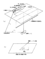
図1に示すように、地表面1の地下に位置する測定対象の信号磁界源としての掘削ヘッド2の位置、すなわち測定しようとする掘削位置の近くに電力線などの雑音磁界を発生する磁気雑音源3が存在する場合に、地表面1上の適当な位置に磁気センサ4を配置して、この磁気センサ4により、信号磁界源としての掘削ヘッド2の位置を測定する場合に、掘削ヘッド2からの信号磁界ベクトルHs と磁気雑音源3からの雑音磁界ベクトルHn とが存在する。この場合、磁気センサ4により測定されるのは、信号磁界ベクトルHs と雑音磁界ベクトルHn とが合成された測定ベクトルHm である。
【0010】
ここで、位置ベクトルr、時刻tにおける雑音磁界をベクトルHn (r,t)とする。一方、磁界発生手段が発生する位置測定用の信号磁界をベクトルHs (r−rc ,θc ,t)とする。ここで、ベクトルθc は磁界発生手段の姿勢角であり、磁界発生手段に固定した座標系の大地に固定した座標系における3個の回転角である。
両者は同時に測定され、かつ雑音磁界ベクトルHn (r,t)は時間によりランダムに変化するから、雑音磁界の統計的な性質が既知で、かつ信号磁界と信号的に直交していない限り、測定磁界ベクトルHm (r−rc ,θc ,t)から信号磁界ベクトルHs (r−rc ,θc ,t)のみを取り出すことはできない。また、仮に雑音磁界を分離するための統計的な性質が位置測定に先立ち得られているとしても、分離のためには大量のデータが必要となり、実用的とは言い難い。
【0011】
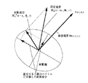
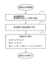
本発明では、雑音磁界ベクトルHn (r,t)のベクトルen (r)の方向を別の手段で得て、図2に示座標系において、図4に示すように、測定磁界ベクトルHm (r−rc ,θc ,t)のベクトルen (r)の方向に垂直な面への射影成分ベクトルHm P (r−rc ,θc ,t)を求める(S1,S2,S3)。
【数1】

【数2】
![]()
【数3】
![]()
【0012】
しかしながら、ベクトルen (r)の方向に垂直な射影面に射影されることにより射影成分ベクトルHm P (r−rc ,θc ,t)は1軸分の情報を失っている。つまり、ベクトルen (r)に平行な成分の大きさに関わらず同じ射影成分が求められるから、独立な成分は2個である。
【0013】
独立な2成分を求める方法としてはどのような方法でも構わないが、例えば以下のような方法が使用可能である。
【0014】
測定座標系CM (測定座標系については後述する)の座標軸のうちで、雑音磁界Hn (r,t)の方向en (r)と平行でない座標軸を1個選ぶ。その座標軸方向の単位ベクトルをベクトルem とする。これと方向en (r)のベクトル積ep,1 =em ×en (r)はベクトルen (r)の方向に直交するから射影面に含まれ、かつ座標軸em と直交する。射影成分ベクトルHm P (r−rc ,θc ,t)をこのベクトルep,1 の方向に射影したものの方向を含めた大きさをHm,1 P (r−rc ,θc ,t)とする。すなわち、
【数4】
【0015】
次に、ベクトルep,1 の方向とベクトルen (r)の方向に直交する方向のベクトルep,2 を求める。ベクトルep,2 の方向はやはり、ベクトルen (r)の方向に直交するから射影面に含まれ、かつベクトルep,1 の方向とも直交する。この方向への射影成分ベクトルHm P (r−rc ,θc ,t)の射影をHm,2 P (r−rc ,θc ,t)とすれば、Hm,1 P (r−rc ,θc ,t)ep,1 とHm,2 P (r−rc ,θc ,t)ep,2 は射影成分ベクトルHm P (r−rc ,θc ,t)を独立な2個のベクトルに分離したものになる。ここで、
【数5】
【0016】
そこで、磁界発生源の位置ベクトルrc 、姿勢角ベクトルθc とした場合に磁界発生源が位置ベクトルrに発生する理論的な磁界を計算した計算磁界ベクトルHe (r−rc ,θc ,t)を測定磁界と同じ平面に射影した射影成分ベクトルHe P (r−rc ,θc ,t)とが実質的に一致するように位置ベクトルrc 、姿勢角ベクトルθc を決めれば、磁界発生源の位置と姿勢を得ることができる。
【0017】
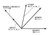
以上の説明は雑音磁界が実質的に1個の場合であったが、雑音磁界が2個存在する場合には、図3に示す座標系において、図5に示すように2個の雑音磁界ベクトルHn,j (r,t),j=1,2の方向をベクトルen1(r)、ベクトルen2(r)とすれば、この両者に直交する方向ベクトルeN (r)=en1(r)×en2(r)への測定磁界の射影を用いる。つまり、
【数6】
【数7】
![]()
【0018】
ここで、磁界発生源の座標をベクトルrc (x,y,z)、磁界発生源の姿勢角をベクトルθc (θx ,θy ,θz )とする。以後、θx を回転角、θy を傾斜角、θz を方位角と呼ぶことにする。信号磁界が軸対称である場合には、対称軸がx−軸であるとみなして、姿勢角をベクトルθc (θy ,θz )とする。
【0019】
雑音磁界源が実質的に1個の場合の図4に示す。図4の処理を各測定地点ごとに繰り返す。また、雑音磁界源が実質的に2個の場合も図5に示す処理を各測定地点ごとに繰り返すことは、図4の場合と同様である。
【0020】
位置と姿勢角の求め方:
(1)座標系と姿勢角の定義:
まず、説明に必要な座標系を定義する。
z−軸を鉛直方向(上向き)とする大地に固定した座標系を設け、これを測定座標系ベクトルCM と呼ぶことによする。x−軸とy−軸は右手系をなすように適当にとる。例えば、測定用フレームの辺を水平面に投影した方向に平行にとる。
この座標系に対する磁界発生源の座標ベクトルrc (x,y,z)、磁界発生源の姿勢角ベクトルθc (θx ,θy ,θz )を求めることが目的である。
一方、磁界発生源の軸方向をx軸とし、磁界発生源が水平に置かれた場合にy−軸が水平で、z−軸が鉛直方向(上向き)であるようにとった座標系を磁界発生源座標系ベクトルCc とする。
【0021】
磁界発生源の姿勢角ベクトルθc は、測定座標系ベクトルCM と座標系ベクトルCc との間の回転角として以下のように定義される。測定座標系ベクトルCM と平行な状態にある座標系ベクトルCc0を、まずz−軸(どちらの座標系でも同じ)の周りに方位角θz を回転する。この座標系を座標系ベクトルCc1とする。次いで、座標系ベクトルCc1のy−軸の周りにその座標系ベクトルCc1を傾斜角θy だけ回転する。この座標系を座標系ベクトルCc2とする。さらに、座標系ベクトルCc2のx−軸の周りにその座標系ベクトルCc2を回転角θx だけ回転する。この回転後の座標系が座標系ベクトルCc となるように姿勢角ベクトルθc を定める。
【0022】
(2)独立な測定量と未知数の説明:
雑音磁界が実質的に1個の場合、1個の場所で磁界を測定すれば2個の独立な測定量が得られる。また、雑音磁界が実質的に2個の場合、1個の場所で磁界を測定すれば1個の独立な測定量が得られる。一方、磁界発生源の座標ベクトルrc (x,y,z)の3個の座標成分は未知数である。方位角θz は地磁気の方向など別の基準がないと求めることができないから、掘削ヘッドが方位センサを備えていない限りこれも未知数となる。掘削ヘッドが磁性体である場合や、掘削ヘッドの近傍に埋設鋼管などの磁性体があると方位センサがあっても正確な方位を求めることができないから、多くの場合、方位角ベクトルθz は未知数となる。傾斜角θy は鉛直方向を検出する傾斜角センサで容易に求めることができるため、既知であることが多い。回転角θx についても傾斜角θy と同様である。特に、信号磁界が軸対称である場合には、対称軸をx−軸とみなせば回転角θx は意味を持たないから、無視することができる。
いずれの場合においても、未知数の個数以上の独立な測定量が得られるように異なる位置で測定磁界を得ればよい。
【0023】
測定系の配置:
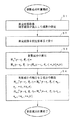
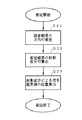
例えば、図1に示すように地上に相互の位置が既知であるように3軸磁気センサを必要な個数配置して磁界を測定する。雑音磁界の方向は測定する場所ごとに異なっている可能性があるから、図6に本発明における位置測定の処理の流れを示しているように雑音磁界の方向を求める処理(S21)と測定磁界の射影成分を求める処理(S22)は各場所ごとに行う必要がある。
【0024】
測定処理の流れ:
雑音磁界の方向の測定(S21)と射影成分による信号磁界源の位置の算出(S23)については以下に詳細に説明する。
【0025】
【実施例】
雑音磁界が実質的に1個の場合の実施例:
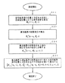
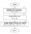
未知数がNU (≧1)1個で、雑音磁界が実質的に1個の場合、図7に示すように、NU /2個以上の異なる場所における測定磁界ベクトルHm (r−rc ,θc ,t)から、(1)式で表される射影成分ベクトルHm P (r−rc ,θc ,t)を求めて、各測定場所での射影成分の理論的な計算磁界の射影成分ベクトルHc P (r−rc ,θc ,t)とが実質的に一致するように位置ベクトルrc 、姿勢角ベクトルθc を決めれば(S31)、磁界発生源の位置と姿勢を得ることができる(S32)。
【0026】
未知数の個数NU (≧1)が偶数である場合、未知数の個数と独立な測定量の個数を一致させることができて、測定磁界ベクトルHm (r−rc ,θc ,t)を得る位置の個数Nm をNm =NU /2とすると
【数8】
【0027】
例えば、未知数が磁界発生源の位置ベクトルrc (x,y,z)と磁界発生源の方位角θz であるときは、異なる2個の測定場所で測定磁界を得て、
【数9】
【0028】
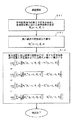
図8に示すように、未知数の個数NU に対してNU /2個以上の異なるNm (>NU /2)個の場所で測定磁界を得た場合には、未知数の個数以上の独立な測定量が得られるから(S41,S42,S43)、
【数10】
【外1】
【数11】
【0029】
なお、以上の説明において測定磁界ベクトルHm (r−rc ,θc ,t)は信号磁界の周波数近傍のみを通過させる帯域通過フィルタを通過した信号であっても、帯域通過フィルタを通さない広帯域な信号であっても構わないが、帯域通過フィルタを通した信号を用いる方がより信頼性が高い位置測定結果を得られる可能性が高い。
【0030】
(雑音磁界が実質的に2個の場合の実施例)
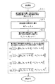
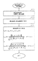
未知数がNU (≧1)個で、雑音磁界が実質的に2個の場合、図9に示すように、NU 個以上の異なる場所における測定磁界ベクトルHm (r−rc ,θc ,t)から、(4)式で表される射影成分ベクトルHm P (r−rc ,θc ,t)を求めて、各測定場所での射影成分の理論的な計算磁界の射影成分ベクトルHe P (r−rc ,θc ,t)とが実質的に一致するように位置ベクトルrc 、姿勢角ベクトルθc を決めれば(S51,S52)、磁界発生源の位置と姿勢を得ることができる(S53)。
【0031】
この場合には必ず未知数の個数NU (≧1)と独立な測定量の個数を一致させることができて、未知数の個数NU と同数の異なる位置で測定磁界ベクトルHm (r−rc ,θc ,t)を得て、
【数12】
【0032】
例えば、未知数が磁界発生源の位置ベクトルrc (x,y,z)と磁界発生源の方位角θz 、傾斜角θy であることき、異なる5個の測定場所で測定磁界を得て、
【数13】
![]()
【0033】
図10に示すように、未知数の個数NU に対してNU 個以上の異なるNm (>NU )個の場所で測定磁界を得た場合には(S61,S62)、未知数の個数以上の独立な測定量が得られるから、
【数14】
【外2】
【0034】
(18)式の代わりに
【数15】
【0035】
なお、以上の説明において測定磁界ベクトルHm (r−rc ,θc ,t)は信号磁界の周波数近傍のみを通過させる帯域通過フィルタを通過した信号であっても、帯域通過フィルタを通さない広帯域な信号であっても構わないが、帯域通過フィルタを通した信号を用いる方がさらに信頼性が高い位置測定結果を得られる可能性が高い。
【0036】
以下、上記の2個の実施例において雑音磁界の方向を得る方法について説明する。
【0037】
(雑音磁界が実質的に1個の場合の雑音磁界の方向の求め方)
(第1の方法)
雑音磁界の方向を求める第1の方法は、信号磁界が無い場合に、信号磁界を測定するのと同一の測定系を用いて雑音磁界を測定する方法である。このような状況としては、図11のように掘削経路の一部に雑音磁界発生源があり、そこでの掘削位置の測定が問題となる場合である。また、信号磁界発生源が、例えば地上から何らかの手段で送信するコマンドを受信する機能があり、コマンドにより信号磁界の発生を随意に停止できる場合である。
【0038】
この場合、図12に示すように、測定磁界をベクトルHm (r−rc ,θc ,t)とするとき、これは実質的に雑音磁界ベクトルHn (r,t)であるから(S71)、その絶対値の平均値を用いて雑音磁界の方向ベクトルen (r)=(en,x (r),en,y (r),en,z (r))は(S72)、
【数16】
【数17】
【外3】
【0039】
なお、以上の説明において測定磁界ベクトルHm (r−rc ,θc ,t)は信号磁界の周波数近傍のみを通過させる帯域通過フィルタを通過した信号であっても、帯域通過フィルタを通さない広帯域な信号であっても構わないが、帯域通過フィルタを通した信号を用いる方がさらに信頼性が高い雑音磁界の方向を得られる可能性が高い。
【0040】
(第2の方法)
ステップ1
図13に示すように、
【外4】
![]()
【数18】
![]()
【外5】
![]()
【0041】
ステップ2
【外6】
【0042】
(1)当該角周波数のフーリエ変換されたx,y,z成分の絶対値を用いて
【数19】
【外7】
![]()
【0043】
(2)角周波数ωi ,i=1,2,…,Nnsに対して当該周波数を通過域の中心周波数とする狭帯域フィルタを形成し、(20)式あるいは(21)式と同様な方法により候補単位ベクトルen (r,ωi ),i=1,…,Nnsを求める。すなわち、
【数20】
【数21】
【0044】
ステップ3
候補単位ベクトルen (r,ωi ),i=1,…,Nnsを雑音磁界の方向ベクトルen (r)と考えて、各角周波数ωi ,i=1,2,…Nnsに対して(1)式と同様な方法で射影成分ベクトルHm P (r−rc ,θc ,ωi ,t)を求める。
【数22】
【0045】
(1)直交する2成分の絶対値の平均
【数23】
【0046】
(2)絶対値の平均
【数24】
(3)直交する2成分の2乗の平均
【数25】
【0048】
(4)直交する2成分の2乗の平均の平方根
【数26】
【0049】
これらの式で計算した統計量veval,k ,k=1,…,Ntestに対して
【数27】
【数28】
【0050】
この角周波数ωi,min を持つ磁界を求める雑音磁界に由来するものであり、雑音磁界の方向はベクトルen (r,ωi,min )となる。
なお、var(ωi ) が最小になる角周波数ωi,min は1箇所で求めれば十分であり、測定磁界を得る個々の場所で行う必要はない。
【0051】
本方法においては(33)式で与えられる振幅の揺らぎの他にベクトルHm P (r−rc ,θc ,ωi ,t)の方向の揺らぎを算出して方向の揺らぎが最小になるかあるいは所定の値以下になる角周波数ωi,min を選ぶことも可能である。
【0052】
なお、以上の説明において、ステップ1では測定磁界ベクトルHm (r−rc ,θc ,t)は広帯域な信号であり、ステップ3では測定磁界ベクトルHm (r−rc ,θc ,t)は信号磁界の周波数近傍のみを通過させる帯域通過フィルタを通過した信号であっても、帯域通過フィルタを通さない広帯域な信号であっても構わないが、帯域通過フィルタを通した信号を用いる方がさらに信頼性が高い雑音磁界の方向を得られる可能性が高い。
【0053】
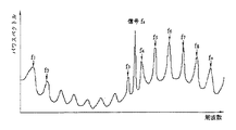
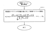
また、本方法において周波数スペクトルが極大となる周波数f1 (=ω1 /2π),f2 (=ω2 /2π),…,fn (=ωn /2π,n=Nns),を選択する様子を図14に、候補ベクトルを求めるステップS91を含む処理の流れを図15に、候補ベクトルの評価と雑音磁界の方向を取得するステップS101,S102又はステップS111,S112を含む処理の流れを図16と図17に示す。
【外8】
![]()
【0054】
(第3の方法)
【外9】
![]()
var(ωi ) が最小になる角周波数ωi,min は1箇所で求めればよいのは第2の方法の場合と同様である。
【0055】
本方法において周波数スペクトルが極大となる周波数f1 (=ω1 /2π),f2 (=ω2 /2π),…,fn (=ωn /2π,n=Nns),を選択する様子を図18に示す。以下の処理の流れは図13,図15,図16に示したものと同様である。
【0056】
(第4の方法)
信号磁界を所定の手順で周期的に停止する。例えば、周期的に所定の時間だけ信号磁界を停止する。信号磁界が停止している間は測定磁界の強度が低下するから、強度の低下が所定の停止期間と実質的にみなせる期間だけ接続することを以て、信号磁界の停止期間を同定し、その停止期間中の測定磁界の方向を雑音ベクトルの方向とする。雑音磁界ベクトルの方向の求め方としては第1の方法と同じ方法を使用できる。この方法における測定磁界の振幅の時間変化の様子を図19に示す。
【0057】
(第5の方法)
信号磁界を所定の手順で周期的に停止する。例えば、次の▲1▼,▲2▼のように行う。
▲1▼ 矩形波的に停止すること:
例えば、周期Tperiodで信号磁界の発信と停止を繰り返す。
【数29】
【数30】
![]()
【0058】
▲2▼ 疑似ランダム信号的に停止すること:
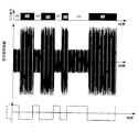
例えば、単位区間Tunitが等しい長さNM のM系列のようなランダムシーケンスにおいて値が「−1」のときには信号磁界を発信し、値が「1」のときには信号磁界を停止するものとして、このシーケンスを繰り返す。
【0059】
▲1▼の方法で信号磁界を停止するときの測定磁界の振幅の時間変化の様子を図20に示す。また、▲2▼の方法で信号磁界を停止するときの測定磁界の振幅の時間変化の様子を図21に示す。
【0060】
次に、図22に示すように、シーケンスs(t)と測定磁界のノルムあるいは特定の成分の絶対値との相関関数を求める(S121,S122,S123)。相関関数としては、相関を求める時間期間を周期Tperiodの整数NT 倍であるNT Tperiodとして
【数31】
【0061】
上記のいずれかの相関関数が最大となる時刻τ=tsyncから(S124)、信号磁界が停止していることを定めることができる(S125)。つまり、時刻τ=tsyncを開始時刻とするシーケンスs(t−tsync)により、そのシーケンスs(t)が「1」のときには信号磁界がオフであるとして信号磁界のオン/オフを決定する。
このように決定した信号磁界の停止時間区間内において測定磁界の方向を求め、その方向を雑音磁界の方向とみなす(S126)。シーケンスs(t)が「−1」(第2の数値)のときに信号を発信し、「1」(第1の数値)のときに停止するものとして、このシーケンスを繰り返す。
【0062】
(第6の方法)
第5の方法と同様に、信号磁界を例えば、以下に示す如き所定の手順で周期的に停止する。
【0063】
(1)矩形波的に停止する。
例えば、周期Tperiodで信号磁界の発信と停止を繰り返す。
【数32】
【数33】
【0064】
(2)疑似ランダム信号的に停止する。
例えば、単位区間Tunitが等しい長さNM のM系列のようなランダムシーケンスs(t)において値が「−1」のときには信号磁界を発信し、値が「1」のときには信号磁界を停止するものとして、このシーケンスを繰り返す。
ただし、シーケンスs(t)を所定の時間単位Δtunitを単位として状態が変化するものであるように選ぶ。また、そのシーケンスの時間平均は「0」である。
【0065】
次に、図23に示すように、第5の方法と同様にシーケンスs(t)と測定磁界のノルムあるいは特定の成分の絶対値との相関関数を求める(S131,S132,S133)。相関関数としては、相関を求める時間期間を周期Tperiodの整数NT 倍であるNT Tperiodとして
【数34】
【0066】
このとき相関関数が極大であり、かつ当該極大値が所定の値以上となる時刻τ=tsync,k ,(k=1,2,…,Nsync)は一般に複数個存在する(S134)。例えば、tsync,k ,(k=1,2,…,Nsync)がこのような時刻を時間が先行する順に並べてるものであるとする。シーケンスs(t)と信号磁界の相関値が適切に求められている場合には、
【数35】
【数36】
【数37】
![]()
【0067】
この時間区間の測定磁界ベクトルHm (r−rc ,θc ,t)に対して第1の方法と同様な方法を適用すれば、雑音磁界ベクトルHn (r,t)の方向en (r)をを求めることができる(S138)。
【0068】
(第7の方法)
図24,図25,図26,図27を参照して説明して説明する。
第5の方法と同様に信号磁界を、例えば、以下に示す如き所定の手順で周期的に停止する。
【0069】
(1)矩形波的に停止する。
例えば、周期Tperiodで信号磁界の発信と停止を繰り返す。
【数38】
【数39】
![]()
【0070】
(2)疑似ランダム信号的に停止する。
例えば、単位区間Tunitが等しい長さNM のM系列のようなランダムシーケンスs(t)において値が「−1」のときには信号磁界を発信し、値が「1」のときには信号磁界を停止するものとして、このシーケンスを繰り返す。ただし、そのシーケンスの時間平均は「0」である。
【0071】
次に、シーケンスs(t)と測定磁界ベクトルHm (r−rc,θc ,t)との時間相関関数を求める(S141,S142,S143)。周期Tperiodを長さTdiv の等間隔のNdiv 個の区間に分割して、以下のいずれかの計算を行う。
【数40】
【外10】
【数41】
![]()
【数42】
【数43】
【0072】
ここで、測定磁界Hm (r−rc ,θc ,t)の各成分x,y,zに対応する
【外11】
![]()
【数44】
![]()
【0073】
本方法では射影成分ベクトルHm (r−rc ,θc ,tk ,t),(k=1,…,Ndiv )の絶対値の揺らぎ
【数45】
【0074】
また、射影成分ベクトルHm (r−rc ,θc ,tk ,t),(k=1,…,Ndiv )のx成分Hm,x (r−rc ,θc ,tk ,t)、y成分Hm,y (r−rc ,θc ,tk ,t)、z成分Hm,z (r−rc ,θc ,tk ,t)のそれぞれの分散
【数46】
【数47】
【数48】
また、シーケンスs(t−tk )から、信号磁界が無い時間区間を容易に設定することができる(S145c,S145d)。この時間区間の測定磁界ベクトルHn (r−rc ,θc ,t)に対して第1の方法と同様な方法を適用すれば、雑音磁界Hn (r,t)の方向en (r)を求めることができる(S146)。
【0075】
上記の説明では周期Tperiodを長さTdiv の等間隔のNdiv 個の区間に分割した時刻tk を用いたが、代わりに(39)式あるいは(40)式で与えられ相関関数が極大となる時刻あるいは相関関数が極大となりかつ所定の値以上となる時刻を用いてもよい。
【0076】
(雑音磁界が実質的に2個の場合の雑音磁界の方向の求め方)
雑音磁界が2個ある場合であっても、ある第1の周波数において第1の雑音磁界が第2の雑音磁気に比べて格段に大きな強度を有し、ある第2の周波数において第2の雑音磁界が第1の雑音磁界に比べて格段に大きな強度を有する場合には、測定磁界中のこれらの周波数成分によって磁界の方向を算出すれば、第1の雑音磁界と第2の雑音磁界の方向を容易に算出することができる。
【0077】
もし、第1の周波数あるいは第2の周波数が信号磁界の周波数と近接している場合には、信号磁界の周波数近傍のみを通過させる帯域通過フィルタを通過した測定磁界に対して、雑音磁界が実質的に1個の場合の第4あるいは第5の方法と同様な方法により雑音磁界の方向を求めることが可能である。
【0078】
第1の周波数と第2の周波数のいずれも信号磁界の周波数と一致しない場合には、雑音磁界が実質的に1個の場合の第1の方法と同様な方法でそれぞれの雑音磁界の方向を算出すればよい。
【0079】
(他の実施例)
本発明は、磁界発生源が発生する信号磁界が実質的に軸対象である場合にも有効であり、対象性が低い磁界に比べてさらに少ない磁気センサの個数あるいはさらに少ない測定場所での測定で位置測定を行うことが可能である。
【0080】
さらに、掘削位置の測定に影響を与える雑音磁界が実質的に1個のみであり、磁界発生源に設定された信号磁界の軸方向と対応する対称軸の鉛直方向からの傾きである傾斜角が既知であるときには、異なる2箇所以上の位置で得た測定磁界に対して、各測定磁界を得た位置で測定した雑音磁界の方向に垂直な平面への射影成分を算出し、その射影成分から、磁界発生源の位置と対称軸の水平面内での方向である方位角とを算出することが可能である。
【0081】
また、本発明方法においては、掘削位置の測定に影響を与える雑音磁界が実質的に1個のみであるときには、異なる3箇所以上の位置で得た測定磁界に対して、各測定磁界を得た位置で測定した雑音磁界の方向に垂直な平面への射影成分を算出し、その射影成分から磁界発生源の位置と磁界発生源に設定された信号磁界の軸方向と対応する対称軸の鉛直方向からの傾きである傾斜角と対称軸の水平面内での方向である方位角とを算出することが可能である。
【0082】
さらに、掘削位置の測定に影響を与える雑音磁界が実質的に2個のみであり、磁界発生源に設定された信号磁界の軸方向と対応する対称軸の鉛直方向からの傾きである傾斜角が既知である場合には、異なる4箇所以上の位置で得た測定磁界に対して、各測定磁界を得た位置で測定した第1の雑音磁界の方向と同じ位置で測定した第2の雑音磁界の方向との両方に垂直な直線への射影成分を算出し、その射影成分から磁界発生源の位置と該対称軸の水平面内での方向である方位角とを算出することが可能である。
【0083】
また、掘削位置の測定に影響を与える雑音磁界が実質的に2個のみであるときには、異なる5箇所以上の位置で得た測定磁界に対して、各測定磁界を得た位置で測定した第1の雑音磁界の方向と同じ位置で測定した第2の雑音磁界の方向との両方に垂直な直線への射影成分を算出し、その射影成分から磁界発生源の位置と磁界発生源に設定された信号磁界の軸方向と対応する対称軸の鉛直方向からの傾きである傾斜角と該対称軸の水平面内での方向である方位角とを算出することが可能である。
【0084】
また、さらに掘削位置の測定に影響を与える雑音磁界が実質的に2個のみであるときには、第1の雑音磁界の周波数成分であって、その周波数成分の周波数の近傍に第2の雑音磁界と信号磁界が実質的に周波数成分を持たないその周波数成分を測定することによって、第1の雑音磁界のベクトルとしての方向を得るとともに、第2の雑音磁界の周波数成分であって、その周波数成分の周波数の近傍に第1の雑音磁界と信号磁界が実質的に周波数成分を持たないその周波数成分を測定することによって、第2の雑音磁界のベクトルとしての方向を得ることが可能である。
【0085】
本発明においては、磁界を測定する磁気センサが実質的に同一場所における互いに直交する3個の軸方向の磁界を測定する3軸磁気センサを用いることが有効である。
【0086】
本発明で用いる磁気センサとしては、実質的に同一の位置における互いに直交する3方向の磁界を測定できるものであればどのようなものでも使用可能であるが、実質的に同一の位置における互いに直交する3方向の磁界を検出する3軸磁気センサが適している。あるいは1方向の磁界のみが測定可能な1個の磁気センサを同一位置において、順次互いに直交する3方向に向けて直交する3方向の磁界を測定することもできる。
【0087】
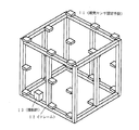
本発明を実施するに当たっては、例えば、図28のように、3軸磁気センサを固定する磁気センサ固定手段11を予め設けたフレーム12に、さらにフレームの鉛直からの傾きを検出する傾斜計13を設けたものを用意することができる。磁気センサ固定手段のフレーム上の位置は既知であり、磁気センサ固定手段は磁気センサをフレームに対して予め定められた所定の姿勢で固定する機能を備えている。磁気センサ固定手段11は、例えば、互いに直交する3面を備えたものであって、磁気センサのケースの所定の面をこれらのいずれかの面に押しつけて所定の角度で磁気センサを固定するような仕組みをもつものである。1個の磁気センサあるいは1個の3軸磁気センサをこれらの磁気センサ固定手段に順次固定しながら測定磁界を得る。
または、フレーム12上の予め定めた複数個の所定の位置に所定の姿勢で複数個の磁気センサを固定しておき、同時の複数の位置で測定磁界を得ることもできる。
【0088】
このように、本発明方法には、3軸磁気センサを設置あるいは固定可能な磁気センサ固定手段を有するフレームであって、そのフレームに固定して設けた直交座標系の鉛直方向に対する傾斜角が検知可能な傾斜角センサを備えたフレーム上に、フレームに対する位置と姿勢が既知であるように設けた所要の個数の前記磁気センサ固定手段に磁気センサを設置あるいは固定してその磁気センサにより磁界を測定して、磁界測定時のフレームの傾斜角と各磁気センサ設置場所における磁気センサのフレームに対する姿勢とを用いて、各磁気センサ設置場所において測定した磁界から測定磁界と雑音磁界と信号磁界を大地に固定した座標系におけるベクトルとして算出することができる。
【0089】
本発明の信号磁界の磁界発生手段としてコイルを用いることができる。または磁界発生手段が一本の電線であっても構わない。さらに位置測定を行っている近傍のみで直線状の1本の電線であってもよい。
【0090】
【発明の効果】
以上の説明したように、本発明によれば、工事現場の近傍に埋設電力線や鉄道線路等の雑音磁界源がある場合でも、これらが発生する雑音磁界の影響を受けることなく、信頼性が高い位置測定が可能となる。
本発明は非開削工法の掘削位置測定法として考案されたが、磁界を測定して位置を測定する多くの分野に応用が可能である。
【図面の簡単な説明】
【図1】本発明方法における磁気センサの配置を説明するための斜視図である。
【図2】雑音磁界源が1個の場合の本発明方法による測定原理を説明するためのベクトル図である。
【図3】雑音磁界源が2個の場合の本発明方法による測定原理を説明するためのベクトル図である。
【図4】雑音磁界源が1個の場合の本発明方法において射影成分を求める処理の流れを示すフロー図である。
【図5】雑音磁界源が2個の場合の本発明方法において射影成分を求める処理の流れを示すフロー図である。
【図6】本発明方法における測定処理の流れを示すフロー図である。
【図7】雑音磁界源が1個の場合の本発明方法において信号磁界の位置算出処理の流れを未知数の個数と方程式の個数が一致する場合について示すフロー図である。
【図8】雑音磁界源が1個の場合の本発明方法において信号磁界の位置算出処理の流れを未知数の個数より方程式の個数が多い場合について示すフロー図である。
【図9】雑音磁界源が2個の場合の本発明方法において信号磁界の位置算出処理の流れを未知数の個数と方程式の個数が一致する場合について示すフロー図である。
【図10】雑音磁界源が2個の場合の本発明方法において信号磁界の位置算出処理の流れを未知数の個数より方程式の個数が多い場合について示すフロー図である。
【図11】信号磁界源である掘削ヘッドが測定場所から離れているときに本発明方法において雑音磁界の方向を測定する配置を説明するための斜視図である。
【図12】本発明方法において雑音磁界の方向算出の流れを掘削ヘッドが測定場所から離れている場合で信号磁界源が磁界発生を停止している場合についてしめすフロー図である。
【図13】本発明方法において雑音磁界の方向算出の流れを信号磁界源と雑音磁界が混在している場合についてしめすフロー図である。
【図14】本発明方法において周波数スペクトルが極大となる周波数選択の動作を図13での雑音磁界の方向を求める処理で用いる方法を説明するための信号周波数スペクトル図である。
【図15】本発明方法において候補ベクトルの算出処理の流れを図13の雑音磁界の方向を求める処理で用いる第1の方法を説明するためのフロー図である。
【図16】本発明方法において候補ベクトルの算出処理の流れを図13の雑音磁界の方向を求める処理で用いる第2の方法を説明するためのフロー図である。
【図17】本発明方法において候補ベクトルの評価と雑音磁界方向を取得する処理の流れを図13の雑音磁界の方向を求める処理で用いる方法を説明するためのフロー図である。
【図18】本発明方法において周波数スペクトルが極大となる周波数選択の動作を図13での雑音磁界の方向を求める処理で用いる方法を説明するための信号周波数スペクトル図である。
【図19】本発明方法において雑音磁界の方向を求める測定方法を、信号磁界を所定の手順で停止して、測定磁界信号の振幅が信号磁界の停止中には小さく成ることを利用して、雑音磁界のみが存在する時間区間を特定動作を説明するための信号波形図である。
【図20】本発明方法における雑音磁界の方向を求める測定方法において、信号磁界を周期的に停止したときの測定磁界信号の振幅の時間変化の様子を示す信号波形図である。
【図21】本発明方法における雑音磁界の方向を求める測定方法において、信号磁界を所定のランダムな手順で停止したときの測定磁界信号の振幅の時間変化の様子を示す信号波形図である。
【図22】本発明方法における雑音磁界の方向を求める測定方法において、信号磁界を所定のシーケンスに基づいて停止し、そのシーケンスと測定磁界の相関関数が最大となる時刻を基点とするシーケンスにより特定磁界が停止している時間区間を特定して、その時間区間内の測定磁界の方向を雑音磁界の方向とする方法をしめすフロー図である。
【図23】本発明方法における雑音磁界の方向を求める測定方法において、信号磁界を所定のシーケンスに基づいて停止し、そのシーケンスと測定磁界の相関関数が極大となる複数の時刻から、最も確からしい信号磁界の発信/停止を表すシーケンスの開始時刻を求める方法をしめすフロー図である。
【図24】本発明方法における雑音磁界の方向を求める測定方法において、信号磁界を所定のシーケンスに基づいて停止し、そのシーケンスと測定磁界の相関関数をシーケンスの周期を等分割した複数の時刻において算出し、その時刻において相関関数がなすベクトルに測定磁界を射影したときの分散が最小となるそのベクトルを雑音磁界の方向とみなす方法をしめすフロー図である。
【図25】本発明方法における雑音磁界の方向を求める測定方法において、信号磁界を所定のシーケンスに基づいて停止し、そのシーケンスと測定磁界の相関関数をシーケンスの周期を等分割した複数の時刻において算出し、その時刻において相関関数がなすベクトルに測定磁界を射影したときの分散が最小となるそのベクトルを雑音磁界の方向とみなす別の評価方法をしめすフロー図である。
【図26】本発明方法における雑音磁界の方向を求める測定方法において、信号磁界を所定のシーケンスに基づいて停止し、そのシーケンスと測定磁界の相関関数が極大となる複数の時刻から、最も確からしい信号磁界の発信/停止を表すシーケンスの開始時刻を求める方法をしめすフロー図である。
【図27】本発明方法における雑音磁界の方向を求める測定方法において、信号磁界を所定のシーケンスに基づいて停止し、そのシーケンスと測定磁界の相関関数をシーケンスの周期を等分割した複数の時刻において算出し、その時刻において相関関数がなすベクトルに測定磁界を射影したときの分散が最小となるそのベクトルを雑音磁界の方向とみなす別の評価方法をしめすフロー図である。
【図28】本発明の実施の際に用いる測定用フレームの構成例を示す斜視図である。
【符号の説明】
1 地表面
2 掘削ヘッド
3 磁気雑音源
4 磁気センサ
11 磁気センサ固定手段
12 フレーム
13 傾斜計[0001]
BACKGROUND OF THE INVENTION
The present invention relates to a method for measuring an excavation position in a non-open cutting method, and particularly when a noise magnetic field having a frequency component exists in the vicinity of the frequency of a signal magnetic field to be measured, the influence of the noise magnetic field is reduced. Thus, the present invention relates to a method for performing position measurement with high accuracy.
[0002]
[Prior art]
In the horizontal drilling method, which is one of these types of non-cutting methods, a small-diameter pipe with a diameter of 100 mm or less is pushed into the ground and digged, so that the precise drilling method used in the ordinary small-diameter propulsion method is used. Position measuring equipment cannot be prepared near the excavation tip. Therefore, a method is generally employed in which an alternating magnetic field is generated by a coil placed in a drill head and the position is measured by detecting the magnetic field with a magnetic sensor such as a ground coil.
[0003]
[Problems to be solved by the invention]
This method is simple, but since the magnetic field generated by the coil is a dipole magnetic field, it is rapidly attenuated as the distance from the coil increases. For this reason, if there is a magnetic noise source such as a power line in the vicinity of the position measurement, there is a drawback that a highly reliable measurement cannot be performed.
[0004]
The object of the present invention is to detect the AC signal magnetic field generated by the coil stored in the excavation head on the ground and measure the excavation position when there is a noise magnetic field that affects the position measurement. It is another object of the present invention to provide a position measurement method that can maintain high reliability.
[0005]
[Means for Solving the Problems]
In order to achieve this object, the excavation position measuring method according to the present invention measures an alternating magnetic field generated from a magnetic field generation source with a magnetic sensor on the ground and calculates the position of the magnetic field generation source from the magnitude and direction. A non-open-cutting method for measuring the excavation position,
When there is a noise magnetic field generated by a nearby current other than the signal magnetic field generated from the magnetic field generation source,
Using a projection component obtained by projecting the measurement magnetic field measured by the magnetic sensor onto a plane or straight line perpendicular to the direction as the vector of the noise magnetic field,
Calculating at least one of a position of the magnetic field generation source, an inclination angle that is an inclination of the magnetic field generation source from a vertical direction, and an azimuth angle that is a direction in a horizontal plane in the axial direction of the magnetic field generation source; It has the composition to do.
[0006]
In other words, in the 1999 “International Research on Effective Utilization of Energy Resources, Research on Technology to Reduce Energy Consumption for Construction of Advanced Communication Network” conducted by the New Energy and Industrial Technology Development Organization, the position measurement in the non-cutting method was affected. It was found that most of the applied external noise magnetic field was generated by some form of current. In this case, the magnitude changes irregularly in time, but the direction as a vector is constant for each measurement point.
In the present invention, the object is achieved by adopting the following steps (a) and (b).
(A) The direction of the noise magnetic field is measured, and a projection component obtained by projecting the measurement magnetic field in which the noise magnetic field and the signal magnetic field are mixed onto a plane or straight line orthogonal to the direction of the noise magnetic field is obtained.
Since the projection component does not include the component derived from the noise magnetic field in principle, the size of the projection component (in the case of projection on a straight line) or the size and direction (in the case of projection on a plane) and a magnetic field generation source are generated. At least one of the position, the azimuth, and the tilt angle of the magnetic field generation source is calculated so that the corresponding value of the magnetic field to be generated is substantially equal to the theoretically calculated value or the difference between the two is minimized.
Measure magnetic field by measuring the magnetic field at a number of different positions determined by how many of the position, azimuth, and tilt angle of the magnetic field source are unknown and the calculation method used to calculate these unknowns. Get.
[0007]
(B) To obtain the direction of the noise magnetic field,
a) When there is substantially one noise magnetic field,
{Circle around (1)} The direction of the noise magnetic field is obtained by measuring the noise magnetic field with substantially no signal magnetic field.
(2) When the noise magnetic field has a frequency component at a frequency different from that of the signal magnetic field, the direction of the noise magnetic field is obtained by measuring the frequency component.
b) When there are substantially two noise magnetic fields,
By measuring the frequency component of the first noise magnetic field, the second noise magnetic field and the signal magnetic field having substantially no frequency component in the vicinity of the frequency of the frequency component, the first noise is measured. A direction as a vector of the magnetic field is obtained, and the frequency component of the second noise magnetic field, the first noise magnetic field and the signal magnetic field having substantially no frequency component in the vicinity of the frequency of the frequency component. Is obtained as a vector of the second noise magnetic field.
[0008]
DETAILED DESCRIPTION OF THE INVENTION
For convenience of explanation, in the following description, “vector” is used for all vectors, but symbols that do not display vector symbols are used.
[0009]
As shown in FIG. 1, a magnetic noise source that generates a noise magnetic field such as a power line near the position of the
[0010]
Here, the noise magnetic field at position vector r and time t is expressed as vector Hn(R, t). On the other hand, a signal magnetic field for position measurement generated by the magnetic field generating means is represented by a vector H.s(R-rc, Θc, T). Where the vector θcIs an attitude angle of the magnetic field generating means, and is three rotation angles in the coordinate system fixed to the ground of the coordinate system fixed to the magnetic field generating means.
Both are measured simultaneously and the noise field vector HnSince (r, t) changes randomly with time, as long as the statistical properties of the noise magnetic field are known and not orthogonal to the signal magnetic field, the measured magnetic field vector Hm(R-rc, Θc, T) from the signal magnetic field vector Hs(R-rc, Θc, T) cannot be extracted. Even if the statistical properties for separating the noise magnetic field are obtained prior to the position measurement, a large amount of data is required for the separation, which is not practical.
[0011]
In the present invention, the noise magnetic field vector HnA vector e of (r, t)nThe direction of (r) is obtained by another means, and in the coordinate system shown in FIG. 2, as shown in FIG.m(R-rc, Θc, T) vector enProjection component vector H onto a plane perpendicular to the direction (r)m P(R-rc, Θc, T) (S1, S2, S3).
[Expression 1]
[Expression 2]
![]()
[Equation 3]
![]()
[0012]
However, the vector enProjection component vector H is projected onto a projection plane perpendicular to the direction (r).m P(R-rc, Θc, T) have lost information for one axis. That is, the vector enSince the same projection component is obtained regardless of the size of the component parallel to (r), there are two independent components.
[0013]
Any method may be used as a method for obtaining two independent components. For example, the following methods can be used.
[0014]
Measurement coordinate system CMAmong the coordinate axes (the measurement coordinate system will be described later), the noise magnetic field HnDirection e of (r, t)nSelect one coordinate axis that is not parallel to (r). The unit vector in the direction of the coordinate axis is the vector emAnd This and direction enVector product e of (r)p, 1= Em× en(R) is the vector enSince it is orthogonal to the direction of (r), it is included in the projection plane and the coordinate axis emOrthogonal to Projection component vector Hm P(R-rc, Θc, T) to this vector ep, 1The size including the direction of the projection in the direction ofm, 1 P(R-rc, Θc, T). That is,
[Expression 4]
[0015]
Next, the vector ep, 1Direction and vector enA vector e in a direction orthogonal to the direction of (r)p, 2Ask for. Vector ep, 2Is still the vector enSince it is orthogonal to the direction of (r), it is included in the projection plane and the vector ep, 1It is also orthogonal to the direction. Projection component vector H in this directionm P(R-rc, Θc, T)m, 2 P(R-rc, Θc, T), Hm, 1 P(R-rc, Θc, T) ep, 1And Hm, 2 P(R-rc, Θc, T) ep, 2Is the projection component vector Hm P(R-rc, Θc, T) are separated into two independent vectors. here,
[Equation 5]
[0016]
Therefore, the position vector r of the magnetic field generation sourcec, Posture angle vector θcThe calculated magnetic field vector H calculated from the theoretical magnetic field generated by the magnetic field generation source in the position vector r.e(R-rc, Θc, T) is projected onto the same plane as the measured magnetic field, and the projection component vector He P(R-rc, Θc, T) substantially coincides with the position vector rc, Posture angle vector θcIs determined, the position and orientation of the magnetic field generation source can be obtained.
[0017]
The above description is for the case where there is substantially one noise magnetic field. However, when there are two noise magnetic fields, two noise magnetic field vectors are used in the coordinate system shown in FIG. 3 as shown in FIG. Hn, jThe direction of (r, t), j = 1, 2 is the vector en1(R), vector en2If (r), then the direction vector e orthogonal to bothN(R) = en1(R) × en2Use the projection of the measured magnetic field on (r). That means
[Formula 6]
[Expression 7]
![]()
[0018]
Here, the coordinates of the magnetic field generation source are represented by the vector rc(X, y, z), the orientation angle of the magnetic field source is represented by the vector θc(Θx, Θy, Θz). Thereafter, θxIs the rotation angle, θyTilt angle, θzIs called the azimuth. If the signal magnetic field is axially symmetric, the symmetric axis is regarded as the x-axis, and the attitude angle is set to the vector θ.c(Θy, Θz).
[0019]
FIG. 4 shows a case where the number of noise magnetic field sources is substantially one. The process of FIG. 4 is repeated for each measurement point. Further, when the number of the noise magnetic field sources is substantially two, the process shown in FIG. 5 is repeated for each measurement point as in the case of FIG.
[0020]
How to find the position and posture angle:
(1)Definition of coordinate system and attitude angle:
First, a coordinate system necessary for explanation is defined.
A coordinate system in which the z-axis is fixed to the ground with the vertical direction (upward) is provided, and this is expressed as a measurement coordinate system vector CMBy calling it. The x-axis and y-axis are appropriately set so as to form a right-handed system. For example, the side of the measurement frame is parallel to the direction projected onto the horizontal plane.
Coordinate vector r of the magnetic field source for this coordinate systemc(X, y, z), attitude angle vector θ of the magnetic field generation sourcec(Θx, Θy, Θz) Is the purpose.
On the other hand, a coordinate system in which the axial direction of the magnetic field generation source is the x-axis and the y-axis is horizontal and the z-axis is vertical (upward) when the magnetic field generation source is placed horizontally is a magnetic field. Source coordinate system vector CcAnd
[0021]
Attitude angle vector θ of the magnetic field sourcecIs the measurement coordinate system vector CMAnd coordinate system vector CcIs defined as follows. Measurement coordinate system vector CMCoordinate system vector C in parallelc0Azimuth θ around the z-axis (same for both coordinate systems)zRotate. This coordinate system is represented by a coordinate system vector Cc1And Next, the coordinate system vector Cc1Its coordinate system vector C around the y-axisc1Tilt angle θyOnly rotate. This coordinate system is represented by a coordinate system vector Cc2And Furthermore, the coordinate system vector Cc2Its coordinate system vector C around the x-axis ofc2Rotation angle θxOnly rotate. The coordinate system after this rotation is the coordinate system vector CcPosture angle vector θcDetermine.
[0022]
(2)Independent measurement and explanation of unknowns:
When the noise magnetic field is substantially one, if the magnetic field is measured at one place, two independent measurement quantities can be obtained. In addition, when there are substantially two noise magnetic fields, one independent measurement amount can be obtained by measuring the magnetic field at one place. On the other hand, the coordinate vector r of the magnetic field sourcecThe three coordinate components of (x, y, z) are unknowns. Azimuth θzSince it cannot be obtained without another standard such as the direction of geomagnetism, this is also an unknown number unless the excavation head is equipped with an orientation sensor. If the excavation head is a magnetic body or if there is a magnetic body such as an embedded steel pipe in the vicinity of the excavation head, the azimuth vector θzBecomes an unknown. Inclination angle θyCan be easily obtained by an inclination angle sensor that detects the vertical direction, and is often known. Rotation angle θxAlso about the tilt angle θyIt is the same. In particular, when the signal magnetic field is axisymmetric, if the symmetry axis is regarded as the x-axis, the rotation angle θxIs meaningless and can be ignored.
In either case, the measurement magnetic field may be obtained at different positions so that an independent measurement quantity equal to or greater than the unknown number can be obtained.
[0023]
Measurement system layout:
For example, as shown in FIG. 1, a required number of three-axis magnetic sensors are arranged on the ground so that the mutual positions are known, and the magnetic field is measured. Since there is a possibility that the direction of the noise magnetic field is different for each place to be measured, the process of obtaining the direction of the noise magnetic field (S21) and the measurement magnetic field as shown in the flow of the position measurement process in the present invention in FIG. It is necessary to perform the process (S22) for obtaining the projection component of each for each location.
[0024]
Measurement process flow:
The measurement of the direction of the noise magnetic field (S21) and the calculation of the position of the signal magnetic field source by the projection component (S23) will be described in detail below.
[0025]
【Example】
Example with substantially one noise magnetic field:
Unknown is NUWhen (≧ 1) 1 and the number of noise magnetic fields is substantially 1, as shown in FIG.U/ Measured magnetic field vector H at two or more different locationsm(R-rc, Θc, T) from the projection component vector H expressed by the equation (1)m P(R-rc, Θc, T) to obtain a theoretical calculation of the projection component at each measurement location.c P(R-rc, Θc, T) substantially coincides with the position vector rc, Posture angle vector θc(S31), the position and orientation of the magnetic field generation source can be obtained (S32).
[0026]
Number of unknowns NUIf (≧ 1) is an even number, the number of unknowns and the number of independent measurement quantities can be matched, and the measurement magnetic field vector Hm(R-rc, Θc, T) The number of positions N to obtainmNm= NU/ 2
[Equation 8]
[0027]
For example, the unknown is a position vector r of the magnetic field source.c(X, y, z) and the azimuth angle θ of the magnetic field sourcezWhen the measurement magnetic field is obtained at two different measurement locations,
[Equation 9]
[0028]
As shown in FIG. 8, the number N of unknownsUN againstU/ 2 or more different Nm(> NU/ 2) When the measurement magnetic field is obtained at the number of locations, an independent measurement quantity equal to or greater than the unknown number is obtained (S41, S42, S43).
[Expression 10]
[Outside 1]
## EQU11 ##
[0029]
In the above description, the measurement magnetic field vector Hm(R-rc, Θc, T) may be a signal that has passed through a bandpass filter that passes only the vicinity of the frequency of the signal magnetic field, or may be a wideband signal that does not pass through the bandpass filter. If it is used, there is a high possibility that a position measurement result with higher reliability can be obtained.
[0030]
(Example when there are substantially two noise magnetic fields)
Unknown is NUWhen (≧ 1) and the number of noise magnetic fields is substantially two, as shown in FIG.UMeasuring magnetic field vector H at more than one different locationm(R-rc, Θc, T) from the projection component vector H expressed by equation (4)m P(R-rc, Θc, T) to obtain a theoretical calculation of the projection component at each measurement location.e P(R-rc, Θc, T) substantially coincides with the position vector rc, Posture angle vector θc(S51, S52), the position and orientation of the magnetic field generation source can be obtained (S53).
[0031]
In this case, the number of unknowns N must beU(≧ 1) can be matched with the number of independent measurement quantities, and the number of unknowns NUMagnetic field vector H at the same number of different positionsm(R-rc, Θc, T)
[Expression 12]
[0032]
For example, the unknown is a position vector r of the magnetic field source.c(X, y, z) and the azimuth angle θ of the magnetic field sourcez, Inclination angle θySo, get the measurement magnetic field at five different measurement locations,
[Formula 13]
![]()
[0033]
As shown in FIG. 10, the number N of unknownsUN againstUN or more different Nm(> NU) When the measurement magnetic field is obtained at a single location (S61, S62), an independent measurement quantity equal to or greater than the unknown number can be obtained.
[Expression 14]
[Outside 2]
[0034]
Instead of (18)
[Expression 15]
[0035]
In the above description, the measurement magnetic field vector Hm(R-rc, Θc, T) may be a signal that has passed through a bandpass filter that passes only the vicinity of the frequency of the signal magnetic field, or may be a wideband signal that does not pass through the bandpass filter. If it is used, there is a high possibility that a position measurement result with higher reliability can be obtained.
[0036]
Hereinafter, a method of obtaining the direction of the noise magnetic field in the above two embodiments will be described.
[0037]
(How to determine the direction of the noise magnetic field when there is substantially one noise magnetic field)
(First method)
The first method for determining the direction of the noise magnetic field is a method of measuring the noise magnetic field using the same measurement system that measures the signal magnetic field when there is no signal magnetic field. As such a situation, there is a noise magnetic field generation source in a part of the excavation path as shown in FIG. 11, and measurement of the excavation position there is a problem. In addition, the signal magnetic field generation source has a function of receiving a command to be transmitted from the ground by some means, for example, and the generation of the signal magnetic field can be arbitrarily stopped by the command.
[0038]
In this case, as shown in FIG.m(R-rc, Θc, T), this is essentially a noisy magnetic field vector HnSince it is (r, t) (S71), the direction vector e of the noise magnetic field is obtained using the average of the absolute values.n(R) = (en, x(R), en, y(R), en, z(R)) is (S72),
[Expression 16]
[Expression 17]
[Outside 3]
[0039]
In the above description, the measurement magnetic field vector Hm(R-rc, Θc, T) may be a signal that has passed through a bandpass filter that passes only the vicinity of the frequency of the signal magnetic field, or may be a wideband signal that does not pass through the bandpass filter. It is more likely that the direction of the noise magnetic field will be obtained with higher reliability.
[0040]
(Second method)
As shown in FIG.
[Outside 4]
![]()
[Expression 18]
![]()
[Outside 5]
![]()
[0041]
[Outside 6]
[0042]
(1) Using the absolute values of the x, y, and z components that are Fourier-transformed at the angular frequency
[Equation 19]
[Outside 7]
![]()
[0043]
(2) Angular frequency ωi, I = 1, 2,..., NnsA narrowband filter having the frequency as the center frequency of the passband is formed, and a candidate unit vector e is obtained by a method similar to the equation (20) or (21).n(R, ωi), I = 1,..., NnsAsk for. That is,
[Expression 20]
[Expression 21]
[0044]
Candidate unit vector en(R, ωi), I = 1,..., NnsThe direction vector e of the noise magnetic fieldn(R), each angular frequency ωi, I = 1, 2,... NnsFor the projection component vector H in the same manner as in equation (1)m P(R-rc, Θc, Ωi, T).
[Expression 22]
[0045]
(1) Average of absolute values of two orthogonal components
[Expression 23]
[0046]
(2) Average absolute value
[Expression 24]
(3) Average of the squares of two orthogonal components
[Expression 25]
[0048]
(4) The square root of the mean square of two orthogonal components
[Equation 26]
[0049]
Statistics v calculated by these formulaseval, k , k = 1, ..., NtestAgainst
[Expression 27]
[Expression 28]
[0050]
This angular frequency ωi, minIs derived from a noise magnetic field to obtain a magnetic field having the direction of the noise magnetic field vector en(R, ωi, min)
Var (ωi) Is the smallest angular frequency ωi, minIt is sufficient if it is obtained at one place, and it is not necessary to carry out at each place where the measurement magnetic field is obtained.
[0051]
In this method, in addition to the amplitude fluctuation given by equation (33), the vector Hm P(R-rc, Θc, Ωi, T) to calculate the fluctuation in the direction, and the angular frequency ω at which the fluctuation in the direction is minimized or less than a predetermined valuei, minIt is also possible to choose.
[0052]
In the above description, in
[0053]
Further, in this method, the frequency f at which the frequency spectrum is maximized1(= Ω1/ 2π), f2(= Ω2/2π),...,fn(= Ωn/ 2π, n = Nns), FIG. 14 shows a state of selecting candidate vectors, FIG. 15 shows a flow of processing including step S91 for obtaining candidate vectors, and includes steps S101, S102 or steps S111, S112 for obtaining candidate vector evaluations and noise magnetic field directions. The flow of processing is shown in FIGS.
[Outside 8]
![]()
[0054]
(Third method)
[Outside 9]
![]()
var (ωi) Is the smallest angular frequency ωi, minIt is the same as in the case of the second method that it may be obtained at one place.
[0055]
Frequency f at which the frequency spectrum is maximized in this method1(= Ω1/ 2π), f2(= Ω2/2π),...,fn(= Ωn/ 2π, n = NnsFIG. 18 shows a state of selecting). The following processing flow is the same as that shown in FIGS.
[0056]
(Fourth method)
The signal magnetic field is periodically stopped by a predetermined procedure. For example, the signal magnetic field is periodically stopped for a predetermined time. Since the strength of the measured magnetic field decreases while the signal magnetic field is stopped, the signal magnetic field stop period is identified by connecting only when the decrease in strength can be substantially regarded as the predetermined stop period. The direction of the measurement magnetic field inside is the direction of the noise vector. As a method for obtaining the direction of the noise magnetic field vector, the same method as the first method can be used. FIG. 19 shows the time variation of the amplitude of the measurement magnetic field in this method.
[0057]
(Fifth method)
The signal magnetic field is periodically stopped by a predetermined procedure. For example, the following (1) and (2) are performed.
(1) Stopping in a square wave:
For example, the period TperiodRepeat the transmission and stop of the signal magnetic field.
[Expression 29]
[30]
![]()
[0058]
(2) Stopping as a pseudo-random signal:
For example, the unit interval TunitEqual length NMIn a random sequence such as the M series, the signal magnetic field is transmitted when the value is “−1”, and the signal magnetic field is stopped when the value is “1”, and this sequence is repeated.
[0059]
FIG. 20 shows how the amplitude of the measured magnetic field changes with time when the signal magnetic field is stopped by the method {circle around (1)}. FIG. 21 shows how the amplitude of the measured magnetic field changes with time when the signal magnetic field is stopped by the method (2).
[0060]
Next, as shown in FIG. 22, a correlation function between the sequence s (t) and the norm of the measurement magnetic field or the absolute value of a specific component is obtained (S121, S122, S123). As a correlation function, the time period for obtaining the correlation is a period TperiodAn integer NTN timesTTperiodAs
[31]
[0061]
Time τ = t at which any of the above correlation functions becomes maximumsync(S124), it can be determined that the signal magnetic field is stopped (S125). That is, time τ = tsyncS (t−tsync), When the sequence s (t) is “1”, it is determined that the signal magnetic field is off, and on / off of the signal magnetic field is determined.
The direction of the measurement magnetic field is obtained within the signal magnetic field stop time interval determined in this way, and the direction is regarded as the direction of the noise magnetic field (S126). This sequence is repeated assuming that a signal is transmitted when the sequence s (t) is “−1” (second numerical value) and stops when the sequence s (t) is “1” (first numerical value).
[0062]
(Sixth method)
Similarly to the fifth method, the signal magnetic field is periodically stopped by a predetermined procedure as shown below, for example.
[0063]
(1) Stop in a rectangular wave.
For example, the period TperiodRepeat the transmission and stop of the signal magnetic field.
[Expression 32]
[Expression 33]
[0064]
(2) Stop as a pseudo-random signal.
For example, the unit interval TunitEqual length NMIn a random sequence s (t) such as the M sequence, the signal magnetic field is transmitted when the value is “−1”, and the signal magnetic field is stopped when the value is “1”, and this sequence is repeated.
However, the sequence s (t) is converted into a predetermined time unit Δt.unitSelect so that the state changes in units of. The time average of the sequence is “0”.
[0065]
Next, as shown in FIG. 23, the correlation function between the sequence s (t) and the norm of the measurement magnetic field or the absolute value of a specific component is obtained as in the fifth method (S131, S132, S133). As a correlation function, the time period for obtaining the correlation is a period TperiodAn integer NTN timesTTperiodAs
[Expression 34]
[0066]
At this time, the time τ = t when the correlation function is maximal and the maximal value is equal to or greater than a predetermined valuesync, k , (K = 1, 2,..., Nsync) Generally exist in plural (S134). For example, tsync, k , (K = 1, 2,..., Nsync) Are arranged in such a order that the times precede. When the correlation value between the sequence s (t) and the signal magnetic field is appropriately obtained,
[Expression 35]
[Expression 36]
[Expression 37]
![]()
[0067]
Measurement magnetic field vector H in this time intervalm(R-rc, Θc, T), if a method similar to the first method is applied, the noise magnetic field vector HnDirection e of (r, t)n(R) can be obtained (S138).
[0068]
(Seventh method)
This will be described with reference to FIGS. 24, 25, 26, and 27. FIG.
Similarly to the fifth method, the signal magnetic field is periodically stopped by a predetermined procedure as shown below, for example.
[0069]
(1) Stop in a rectangular wave.
For example, the period TperiodRepeat the transmission and stop of the signal magnetic field.
[Formula 38]
[39]
![]()
[0070]
(2) Stop as a pseudo-random signal.
For example, the unit interval TunitEqual length NMIn a random sequence s (t) such as the M sequence, the signal magnetic field is transmitted when the value is “−1”, and the signal magnetic field is stopped when the value is “1”, and this sequence is repeated. However, the time average of the sequence is “0”.
[0071]
Next, the sequence s (t) and the measured magnetic field vector Hm(R-rc,θc, T) is obtained (S141, S142, S143). Period TperiodLength TdivEqually spaced NdivDivide into sections and do one of the following calculations:
[Formula 40]
[Outside 10]
[Expression 41]
![]()
[Expression 42]
[Equation 43]
[0072]
Where the measurement magnetic field Hm(R-rc, Θc, T) corresponding to each component x, y, z
[Outside 11]
![]()
(44)
![]()
[0073]
In this method, the projection component vector Hm(R-rc, Θc, Tk, T), (k = 1,..., Ndiv) Fluctuation of absolute value
[Equation 45]
[0074]
Also, the projection component vector Hm(R-rc, Θc, Tk, T), (k = 1,..., NdivX component H)m, x(R-rc, Θc, Tk, T), y component Hm, y(R-rc, Θc, Tk, T), z component Hm, z(R-rc, Θc, Tk, T)
[Equation 46]
[Equation 47]
[Formula 48]
Also, the sequence s (t−tk), It is possible to easily set a time interval without a signal magnetic field (S145c, S145d). Measurement magnetic field vector H in this time intervaln(R-rc, Θc, T), if a method similar to the first method is applied, the noise magnetic field HnDirection e of (r, t)n(R) can be obtained (S146).
[0075]
In the above description, the period TperiodLength TdivEqually spaced NdivTime t divided into individual sectionskHowever, the time when the correlation function is maximized or the correlation function is maximized and is equal to or greater than a predetermined value given by the equation (39) or (40) may be used instead.
[0076]
(How to determine the direction of the noise magnetic field when there are essentially two noise magnetic fields)
Even when there are two noise magnetic fields, the first noise magnetic field has a significantly larger intensity than the second noise magnetism at a certain first frequency, and the second noise at a certain second frequency. When the magnetic field has a remarkably large intensity compared to the first noise magnetic field, the direction of the first noise magnetic field and the second noise magnetic field can be calculated by calculating the direction of the magnetic field from these frequency components in the measurement magnetic field. Can be easily calculated.
[0077]
If the first frequency or the second frequency is close to the frequency of the signal magnetic field, the noise magnetic field is substantially smaller than the measurement magnetic field that has passed through the band-pass filter that passes only the vicinity of the frequency of the signal magnetic field. Thus, the direction of the noise magnetic field can be obtained by a method similar to the fourth or fifth method.
[0078]
When neither the first frequency nor the second frequency matches the frequency of the signal magnetic field, the direction of each noise magnetic field is set in the same manner as in the first method when the number of the noise magnetic fields is substantially one. What is necessary is just to calculate.
[0079]
(Other examples)
The present invention is also effective when the signal magnetic field generated by the magnetic field generation source is substantially an axis target, and can be used for measurement at a smaller number of magnetic sensors or at a smaller number of measurement locations than a magnetic field with low targetability. Position measurements can be made.
[0080]
Furthermore, there is substantially only one noise magnetic field that affects the measurement of the excavation position, and the inclination angle that is the inclination from the vertical direction of the symmetry axis corresponding to the axial direction of the signal magnetic field set in the magnetic field generation source is When known, in the direction of the noise magnetic field measured at the position where each measurement magnetic field was obtained with respect to the measurement magnetic field obtained at two or more different positions.DroopingIt is possible to calculate a projection component on a straight plane, and calculate the position of the magnetic field generation source and the azimuth, which is the direction of the symmetry axis in the horizontal plane, from the projection component.
[0081]
Further, in the method of the present invention, when there is substantially only one noise magnetic field that affects the measurement of the excavation position, each measurement magnetic field was obtained with respect to the measurement magnetic fields obtained at three or more different positions. In the direction of the noise magnetic field measured at the positionDroopingCalculate the projection component onto the straight plane, and symmetric with the tilt angle, which is the tilt from the vertical direction of the symmetry axis corresponding to the position of the magnetic field generation source and the axial direction of the signal magnetic field set in the magnetic field generation source from the projection component It is possible to calculate the azimuth, which is the direction of the axis in the horizontal plane.
[0082]
Furthermore, there are substantially only two noise magnetic fields that affect the measurement of the excavation position, and the inclination angle that is the inclination from the vertical direction of the symmetry axis corresponding to the axial direction of the signal magnetic field set in the magnetic field generation source is If known, the second noise magnetic field measured at the same position as the direction of the first noise magnetic field measured at the position where each measurement magnetic field was obtained with respect to the measurement magnetic field obtained at four or more different positions. Both in the direction ofDroopingIt is possible to calculate a projection component to a straight line, and to calculate the position of the magnetic field generation source and the azimuth angle that is the direction of the symmetry axis in the horizontal plane from the projection component.
[0083]
Further, when there are substantially only two noise magnetic fields that affect the measurement of the excavation position, the first measurement is performed at the position where each measurement magnetic field is obtained with respect to the measurement magnetic fields obtained at five or more different positions. Both in the direction of the second noise magnetic field measured at the same position as the direction of the noise magnetic field ofDroopingA projection component to a straight line is calculated, and from the projection component, the position of the magnetic field generation source and the inclination angle that is the inclination from the vertical direction of the symmetry axis corresponding to the axial direction of the signal magnetic field set in the magnetic field generation source It is possible to calculate the azimuth angle which is the direction of the symmetry axis in the horizontal plane.
[0084]
Further, when there are substantially only two noise magnetic fields that affect the measurement of the excavation position, the frequency component of the first noise magnetic field, and the second noise magnetic field in the vicinity of the frequency of the frequency component By measuring the frequency component of the signal magnetic field that has substantially no frequency component, the direction as the vector of the first noise magnetic field is obtained, and the frequency component of the second noise magnetic field, By measuring the frequency components of the first noise magnetic field and the signal magnetic field that have substantially no frequency component in the vicinity of the frequency, it is possible to obtain the direction as the vector of the second noise magnetic field.
[0085]
In the present invention, it is effective to use a three-axis magnetic sensor that measures magnetic fields in three axial directions orthogonal to each other at substantially the same place.
[0086]
As the magnetic sensor used in the present invention, any sensor can be used as long as it can measure magnetic fields in three directions orthogonal to each other at substantially the same position, but orthogonal to each other at substantially the same position. A three-axis magnetic sensor that detects magnetic fields in three directions is suitable. Alternatively, a single magnetic sensor capable of measuring only a magnetic field in one direction can be measured in three directions perpendicular to each other in three directions orthogonal to each other at the same position.
[0087]
In practicing the present invention, for example, as shown in FIG. 28, an inclinometer 13 for detecting the inclination of the frame from the vertical is further provided on a
Alternatively, a plurality of magnetic sensors can be fixed in a predetermined posture on a plurality of predetermined positions on the
[0088]
As described above, the method of the present invention is a frame having magnetic sensor fixing means capable of installing or fixing a three-axis magnetic sensor, and an inclination angle with respect to the vertical direction of an orthogonal coordinate system fixed to the frame is detected. A magnetic sensor is installed on or fixed to the required number of magnetic sensor fixing means provided so that the position and posture with respect to the frame are known on a frame having a possible tilt angle sensor, and a magnetic field is measured by the magnetic sensor. Using the tilt angle of the frame at the time of magnetic field measurement and the attitude of the magnetic sensor to the frame at each magnetic sensor installation location, the measured magnetic field, noise magnetic field and signal magnetic field from the magnetic field measured at each magnetic sensor installation location to the ground. It can be calculated as a vector in a fixed coordinate system.
[0089]
A coil can be used as the magnetic field generating means for the signal magnetic field of the present invention. Alternatively, the magnetic field generating means may be a single electric wire. Furthermore, it may be a single linear wire only in the vicinity where position measurement is performed.
[0090]
【The invention's effect】
As described above, according to the present invention, even when there is a noise magnetic field source such as an embedded power line or a railway line in the vicinity of the construction site, the reliability is high without being affected by the noise magnetic field generated by these. Position measurement is possible.
Although the present invention was devised as a method for measuring the excavation position of the non-open cutting method, it can be applied to many fields in which the position is measured by measuring a magnetic field.
[Brief description of the drawings]
FIG. 1 is a perspective view for explaining the arrangement of magnetic sensors in the method of the present invention.
FIG. 2 is a vector diagram for explaining the measurement principle according to the method of the present invention when there is one noise magnetic field source.
FIG. 3 is a vector diagram for explaining the measurement principle according to the method of the present invention when there are two noise magnetic field sources.
FIG. 4 is a flowchart showing a flow of processing for obtaining a projection component in the method of the present invention when there is one noise magnetic field source.
FIG. 5 is a flowchart showing the flow of processing for obtaining a projection component in the method of the present invention when there are two noise magnetic field sources.
FIG. 6 is a flowchart showing the flow of measurement processing in the method of the present invention.
FIG. 7 is a flowchart showing the flow of signal magnetic field position calculation processing when the number of unknowns and the number of equations match in the method of the present invention when there is one noise magnetic field source.
FIG. 8 is a flowchart showing the flow of signal magnetic field position calculation processing when the number of equations is larger than the number of unknowns in the method of the present invention when there is one noise magnetic field source.
FIG. 9 is a flowchart showing the flow of signal magnetic field position calculation processing in the method of the present invention when there are two noise magnetic field sources when the number of unknowns and the number of equations match.
FIG. 10 is a flowchart showing the flow of signal magnetic field position calculation processing when the number of equations is larger than the number of unknowns in the method of the present invention when there are two noise magnetic field sources.
FIG. 11 is a perspective view for explaining an arrangement for measuring the direction of a noise magnetic field in the method of the present invention when the excavation head as a signal magnetic field source is away from the measurement location.
FIG. 12 is a flowchart showing the flow of calculating the direction of the noise magnetic field in the method of the present invention when the excavation head is away from the measurement location and the signal magnetic field source stops generating the magnetic field.
FIG. 13 is a flowchart showing the flow of calculating the direction of the noise magnetic field in the method of the present invention when a signal magnetic field source and a noise magnetic field are mixed.
14 is a signal frequency spectrum diagram for explaining a method of using the frequency selection operation in which the frequency spectrum is maximized in the method of the present invention in the processing for determining the direction of the noise magnetic field in FIG.
15 is a flowchart for explaining a first method that uses the flow of candidate vector calculation processing in the method of the present invention in the processing for determining the direction of the noise magnetic field in FIG. 13; FIG.
16 is a flowchart for explaining a second method of using the candidate vector calculation process flow in the process for obtaining the direction of the noise magnetic field in FIG. 13 in the method of the present invention.
17 is a flowchart for explaining a method of using the process flow for obtaining candidate vector evaluation and the noise magnetic field direction in the method of the present invention in the process for obtaining the noise magnetic field direction in FIG.
18 is a signal frequency spectrum diagram for explaining a method of using the frequency selection operation in which the frequency spectrum is maximized in the method of the present invention in the processing for determining the direction of the noise magnetic field in FIG.
FIG. 19 shows a measurement method for determining the direction of the noise magnetic field in the method of the present invention by using the fact that the signal magnetic field is stopped in a predetermined procedure and the amplitude of the measurement magnetic field signal becomes smaller during the stop of the signal magnetic field. It is a signal waveform diagram for demonstrating specific operation | movement in the time interval in which only a noise magnetic field exists.
FIG. 20 is a signal waveform diagram showing how the amplitude of the measurement magnetic field signal changes with time when the signal magnetic field is periodically stopped in the measurement method for determining the direction of the noise magnetic field in the method of the present invention.
FIG. 21 is a signal waveform diagram showing how the amplitude of the measurement magnetic field signal changes with time when the signal magnetic field is stopped in a predetermined random procedure in the measurement method for determining the direction of the noise magnetic field in the method of the present invention.
FIG. 22 shows a measurement method for determining the direction of a noise magnetic field in the method of the present invention, in which a signal magnetic field is stopped based on a predetermined sequence and specified by a sequence based on a time point at which the correlation function between the sequence and the measured magnetic field is maximum. It is a flowchart which shows the method of specifying the time interval which a magnetic field has stopped, and making the direction of the measurement magnetic field in the time interval the direction of a noise magnetic field.
FIG. 23 shows a measurement method for determining the direction of a noise magnetic field in the method of the present invention. The signal magnetic field is stopped based on a predetermined sequence, and the most probable from a plurality of times when the correlation function between the sequence and the measurement magnetic field becomes maximum. It is a flowchart which shows the method of calculating | requiring the start time of the sequence showing transmission / stop of a signal magnetic field.
FIG. 24 shows a measurement method for determining the direction of a noise magnetic field in the method of the present invention. The signal magnetic field is stopped based on a predetermined sequence, and the correlation function of the sequence and the measurement magnetic field is divided into a plurality of times when the period of the sequence is equally divided. FIG. 10 is a flow diagram showing a method of calculating and regarding the vector having the minimum dispersion when projecting the measurement magnetic field onto the vector formed by the correlation function at that time, as the direction of the noise magnetic field.
FIG. 25 shows a measurement method for determining the direction of the noise magnetic field in the method of the present invention. The signal magnetic field is stopped based on a predetermined sequence, and the correlation function of the sequence and the measurement magnetic field is divided into a plurality of times when the period of the sequence is equally divided. FIG. 10 is a flow diagram showing another evaluation method in which a vector that has a minimum variance when a measured magnetic field is projected onto a vector formed by a correlation function at that time is regarded as the direction of the noise magnetic field.
FIG. 26 shows a measurement method for determining the direction of a noise magnetic field according to the method of the present invention. The signal magnetic field is stopped based on a predetermined sequence, and the most probable from a plurality of times when the correlation function between the sequence and the measurement magnetic field becomes maximum. It is a flowchart which shows the method of calculating | requiring the start time of the sequence showing transmission / stop of a signal magnetic field.
FIG. 27 shows a measurement method for determining the direction of a noise magnetic field in the method of the present invention. The signal magnetic field is stopped based on a predetermined sequence, and the correlation function of the sequence and the measurement magnetic field is divided into a plurality of times at which the sequence period is equally divided. FIG. 10 is a flow diagram showing another evaluation method in which a vector that has a minimum variance when a measured magnetic field is projected onto a vector formed by a correlation function at that time is regarded as the direction of the noise magnetic field.
FIG. 28 is a perspective view showing a configuration example of a measurement frame used in the practice of the present invention.
[Explanation of symbols]
1 Ground surface
2 Drilling head
3 Magnetic noise sources
4 Magnetic sensor
11 Magnetic sensor fixing means
12 frames
13 Inclinometer
Claims (25)
前記磁界発生源から発生されている信号磁界以外に近傍の電流によって発生する雑音磁界が存在する場合に、
前記磁気センサで測定した前記測定磁界を、該雑音磁界のベクトルとしての方向と直交する平面上あるいは直線上に射影した射影成分を用いて、
前記磁界発生源の位置と該磁界発生源の鉛直方向からの傾きである傾斜角と該磁界発生源の軸方向の水平面内での方向である方位角の少なくとも1個を算出する掘削位置測定方法。An excavation position measurement method using a non-opening method in which an alternating magnetic field generated from a magnetic field source is measured with a magnetic sensor on the ground, and the position of the magnetic field source is calculated from the magnitude and direction of the measured magnetic field. There,
When there is a noise magnetic field generated by a nearby current other than the signal magnetic field generated from the magnetic field generation source,
Using the projection component obtained by projecting the measurement magnetic field measured by the magnetic sensor onto a plane or straight line perpendicular to the direction as the vector of the noise magnetic field,
Excavation position measuring method for calculating at least one of a position of the magnetic field generation source, an inclination angle that is an inclination of the magnetic field generation source from a vertical direction, and an azimuth angle that is a direction in a horizontal plane in the axial direction of the magnetic field generation source .
該ベクトルとしての方向に直交する面あるいは線に該測定磁界を射影した射影成分の振幅あるいは方向の揺らぎが最小となるかあるいは所定の値以下になる該雑音磁界の周波数成分のベクトルとして方向を、前記信号磁界と同じ周波数成分の前記雑音磁界のベクトルとしての方向とすることを特徴とする請求項3に記載の掘削位置測定方法。Calculate the direction as a vector for each of the frequency components of the measurement magnetic field having a frequency different from the signal magnetic field,
The direction as the vector of the frequency component of the noise magnetic field where the amplitude or direction fluctuation of the projection component obtained by projecting the measurement magnetic field onto the plane or line orthogonal to the direction as the vector is minimized or less than a predetermined value, 4. The excavation position measuring method according to claim 3, wherein the direction is a vector as the noise magnetic field having the same frequency component as the signal magnetic field.
該ベクトルとしての方向に直交する面あるいは線に前記測定磁界を射影した射影成分の振幅の揺らぎあるいは方向の揺らぎが最小となるかあるいは所定の値以下になる該雑音磁界の線スペクトル成分のベクトルとしての方向を、前記信号磁界と同じ周波数成分の前記雑音磁界のベクトルとしての方向とすることを特徴とする請求項4に記載の掘削位置測定方法。Calculate the direction as a vector for each of the line spectral components of the noise magnetic field at a frequency different from the signal magnetic field,
As a vector of the line spectrum component of the noise magnetic field in which the amplitude fluctuation or direction fluctuation of the projection component obtained by projecting the measurement magnetic field onto a plane or line orthogonal to the direction as the vector is minimized or less than a predetermined value The excavation position measuring method according to claim 4, wherein the direction is a direction as a vector of the noise magnetic field having the same frequency component as the signal magnetic field.
前記信号磁界が停止している期間には第1の数値をとり、該信号磁界を発生している期間には該第1の数値と異なる第2の数値をとり、時間平均が「0」の時間関数であるシーケンスと前記測定磁界の絶対値もしくはその絶対値の2乗の平方根、または前記測定磁界のベクトルとしての各成分の絶対値もしくはその絶対値の2乗の平方根との有限時間期間における時間相関関数を算出し、
前記第1の数値が前記第2の数値より大きいときには前記時間相関関数の最大値を与え、前記第1の数値が前記第2の数値より小さいときには前記時間相関関数の最小値を与える前記シーケンスの開始時刻を起点とする該シーケンスにより前記信号磁界が停止している時間区間を設定し、該時間区間内の前記測定磁界の方向を雑音磁界の方向とみなすことを特徴とする請求項6に記載の掘削位置測定方法。The signal magnetic field is periodically stopped in a predetermined procedure,
The first numerical value is taken during the period in which the signal magnetic field is stopped, the second numerical value different from the first numerical value is taken during the period in which the signal magnetic field is being generated, and the time average is “0”. In a finite time period between the sequence that is a time function and the absolute value of the measurement magnetic field or the square root of the absolute value thereof, or the absolute value of each component or the square root of the absolute value of the component as a vector of the measurement magnetic field Calculate the time correlation function,
When the first numerical value is greater than the second numerical value, the maximum value of the time correlation function is provided; and when the first numerical value is smaller than the second numerical value, the minimum value of the time correlation function is provided. The time interval in which the signal magnetic field is stopped is set by the sequence starting from the start time, and the direction of the measurement magnetic field in the time interval is regarded as the direction of the noise magnetic field. Excavation position measurement method.
前記信号磁界が停止している期間には第1の数値をとり、該信号磁界を発生している期間には該第1の数値と異なる第2の数値をとり、時間平均が「0」の時間関数であるシーケンスであって、所定の時間単位を以て前記信号磁界の発信と停止を行うシーケンスにしたがって前記信号磁界を発信および停止し、
前記測定磁界の絶対値もしくはその絶対値の2乗の平方根、または前記測定磁界のベクトルとしての各成分の絶対値もしくは絶対値の2乗の平方根との有限時間期間における時間相関関数を算出し、
前記第1の数値が前記第2の数値より大きいときには、該時間相関関数の所定の値以上の極大値を与え、前記第1の数値が前記第2の数値より小さいときには前記時間相関関数の最小値を与える前記シーケンスの開始時刻を複数個求め、
該複数個の開始時刻の内の最先のものを残りの開始時刻から差し引いた時間差から、該時間差に最も近い前記時間単位の整数倍を除いたものの平均値を求め、 該平均値と前記最先の開始時刻との和の時刻を開始時刻を起点とするシーケンスにより信号磁界が停止している時間区間を設定し、該時間区間内の前記測定磁界の方向を雑音磁界の方向とみなすことを特徴とする請求項6に記載の掘削位置測定方法。The signal magnetic field is periodically stopped in a predetermined procedure,
The first numerical value is taken during the period in which the signal magnetic field is stopped, the second numerical value different from the first numerical value is taken during the period in which the signal magnetic field is being generated, and the time average is “0”. A sequence that is a time function, transmitting and stopping the signal magnetic field according to a sequence for transmitting and stopping the signal magnetic field with a predetermined time unit,
Calculating a time correlation function in a finite time period with the absolute value of the measurement magnetic field or the square root of the absolute value thereof, or the absolute value of each component as the vector of the measurement magnetic field or the square root of the square of the absolute value;
When the first numerical value is larger than the second numerical value, a maximum value greater than or equal to a predetermined value of the time correlation function is given, and when the first numerical value is smaller than the second numerical value, the minimum of the time correlation function is given. Obtaining a plurality of start times of the sequence giving values,
An average value is obtained by subtracting an integral multiple of the time unit closest to the time difference from the time difference obtained by subtracting the earliest one of the plurality of start times from the remaining start time, and calculating the average value and the maximum value. A time interval in which the signal magnetic field is stopped is set by a sequence starting from the start time with the sum of the previous start time and the direction of the measurement magnetic field in the time interval is regarded as the direction of the noise magnetic field. The excavation position measuring method according to claim 6, wherein the excavation position is measured.
該信号磁界が停止している期間には第1の数値をとり、該信号磁界を発生している期間には該第1の数値と異なる第2の数値をとり、時間平均が「0」であるシーケンスと前記測定磁界のベクトルとしての3個の成分の各成分の絶対値あるいは絶対値の2乗の平方根との有限時間関数における時間相関関数である3個の時間相関関数を算出し、
前記3個の時間相関関数がなすベクトルの方向に直交する面あるいは線に前記測定磁界を射影した射影成分の振幅あるいは方向の揺らぎが最小となるかあるいは所定の値以下になるときの該ベクトルの方向を、前記雑音磁界の方向とすることを特徴とする請求項6に記載の掘削位置測定方法。The signal magnetic field is periodically stopped in a predetermined procedure,
The first numerical value is taken during the period when the signal magnetic field is stopped, the second numerical value different from the first numerical value is taken during the period when the signal magnetic field is generated, and the time average is “0”. Calculating three time correlation functions which are time correlation functions in a finite time function of a certain sequence and the absolute value of each of the three components as a vector of the measurement magnetic field or the square root of the square of the absolute value;
The amplitude or direction fluctuation of the projection component obtained by projecting the measurement magnetic field onto a plane or line orthogonal to the direction of the vector formed by the three time correlation functions is minimized or less than a predetermined value. The excavation position measuring method according to claim 6, wherein the direction is a direction of the noise magnetic field.
前記信号磁界を停止する周期以上の期間を前記信号磁界の停止期間以下の時間長の時間区間に分割し、該各時間区間において前記測定磁界に対するベクトルとしての方向を測定し、
該各時間区間の該測定磁界のベクトルとしての方向に直交する面あるいは線に該測定磁界を射影した射影成分の振幅もしくは方向の揺らぎが最小となるかまたは所定の値以下になる時間区間のベクトルとして方向を、前記雑音磁界のベクトルとしての方向とすることを特徴とする請求項6に記載の掘削位置測定方法。The signal magnetic field is periodically stopped in a predetermined procedure,
Dividing a period equal to or longer than the period for stopping the signal magnetic field into time sections having a time length equal to or shorter than the stop period of the signal magnetic field, and measuring a direction as a vector with respect to the measurement magnetic field in each time period;
A vector of a time interval in which the fluctuation of the amplitude or direction of the projection component obtained by projecting the measurement magnetic field onto the plane or line orthogonal to the direction as the vector of the measurement magnetic field in each time interval is minimized or less than a predetermined value 7. The excavation position measuring method according to claim 6, wherein the direction is a direction as a vector of the noise magnetic field.
前記信号磁界が停止している期間には第1の数値をとり、信号磁界を発生している期間には該第1の数値と異なる第2の数値をとり、時間平均が「0」の時間関数であるシーケンスと測定磁界のベクトルとしての3成分の絶対値もしくはその絶対値の2乗の平方根との有限時間期間における時間相関関数を算出し、
1回の前記シーケンスを実行する時間を前記信号磁界の停止期間以下の時間長の時間区間に分割し、各時間区間の代表時刻にける前記時間相関関数の3成分がなすベクトルに直交する面もしくは線に測定磁界を射影した射影成分の振幅または方向の揺らぎが最小となるかもしくは所定の値以下になる時間区間のベクトルとして方向を、前記雑音磁界のベクトルとしての方向とすることを特徴とする請求項6に記載の掘削位置測定方法。The signal magnetic field is periodically stopped in a predetermined procedure,
The first numerical value is taken during the period in which the signal magnetic field is stopped, the second numerical value different from the first numerical value is taken during the period in which the signal magnetic field is generated, and the time average is “0”. Calculating a time correlation function in a finite time period between the function sequence and the absolute value of the three components as the vector of the measured magnetic field or the square root of the square of the absolute value
A time for executing the sequence once is divided into time sections having a length of time equal to or less than the stop period of the signal magnetic field, and a plane orthogonal to a vector formed by three components of the time correlation function at a representative time of each time section or A direction as a vector of a time interval in which fluctuation of the amplitude or direction of a projection component obtained by projecting a measurement magnetic field onto a line is minimized or less than a predetermined value is set as a direction as a vector of the noise magnetic field The excavation position measuring method according to claim 6.
前記磁界発生源に設定された前記信号磁界の軸方向と対応する前記対称軸の鉛直からの傾きである傾斜角が既知であるときに、
異なる2箇所以上の位置で得た他の測定磁界に対して、
該他の各測定磁界を得た位置で測定した前記雑音磁界の方向に垂直な平面への射影成分を算出し、該射影成分から、
前記磁界発生源の位置と、
該対称軸の水平面内での方向である方位角と
を算出することを特徴とする請求項13に記載の掘削位置測定方法。There is substantially only one noisy magnetic field that affects the measurement of the excavation position;
When an inclination angle that is an inclination from the vertical of the symmetry axis corresponding to the axial direction of the signal magnetic field set in the magnetic field generation source is known,
For other measurement magnetic fields obtained at two or more different positions,
Calculating a projection component to the vertical plane in the direction of the noise magnetic field measured at the position to give the said other respective measuring field, the projective component,
The position of the magnetic field source;
14. The excavation position measuring method according to claim 13, wherein an azimuth angle that is a direction in a horizontal plane of the symmetry axis is calculated.
異なる3箇所以上の位置で得た他の測定磁界に対して、
該各測定磁界を得た位置で測定した前記雑音磁界の方向に垂直な平面への射影成分を算出し、該射影成分から、
前記磁界発生源の位置と、
該磁界発生源に設定された前記信号磁界の軸方向と対応する対称軸の鉛直方向からの傾きである傾斜角と、
該対称軸の水平面内での方向である方位角と
を算出することを特徴とする請求項1に記載の掘削位置測定方法。When there is substantially only one noisy magnetic field affecting the measurement of the excavation position,
For other measured magnetic fields obtained at three or more different positions,
Calculating a projection component to the vertical plane in the direction of the noise magnetic field measured at the position to give the respective measuring field, the projective component,
The position of the magnetic field source;
An inclination angle which is an inclination from the vertical direction of the symmetry axis corresponding to the axial direction of the signal magnetic field set in the magnetic field generation source;
The digging position measuring method according to claim 1, wherein an azimuth angle which is a direction in a horizontal plane of the symmetry axis is calculated.
前記磁界発生源に設定された前記信号磁界の軸方向と対応する対称軸の鉛直方向からの傾きである傾斜角が既知であるときに、
異なる4箇所以上の位置で得た前記測定磁界に対して、
該各測定磁界を得た位置で測定した前記第1の雑音磁界と前記第2の雑音磁界の各方向との該両方向に垂直な直線への射影成分を算出し、該射影成分から、
前記磁界発生源の位置と、
該対称軸の水平面内での方向である方位角と
を算出することを特徴とする請求項1に記載の掘削位置測定方法。There are substantially only two noise magnetic fields, the first noise magnetic field and the second noise magnetic field, that affect the measurement of the excavation position;
When an inclination angle that is an inclination from a vertical direction of a symmetry axis corresponding to an axial direction of the signal magnetic field set in the magnetic field generation source is known,
For the measurement magnetic field obtained at four or more different positions,
Calculating a projection component of the both said direction to vertical straight line between each direction of the first noise magnetic field and the second noise magnetic field measured at the position to give the respective measuring field, the projective component,
The position of the magnetic field source;
The digging position measuring method according to claim 1, wherein an azimuth angle which is a direction in a horizontal plane of the symmetry axis is calculated.
異なる5箇所以上の位置で得た前記測定磁界に対して、
該各測定磁界を得た位置で測定した該第1の雑音磁界と該第2の雑音磁界の方向との該両方向に垂直な直線への射影成分を算出し、該射影成分から
前記磁界発生源の位置と、
該磁界発生源に設定された前記信号磁界の軸方向と対応する対称軸の鉛直方向からの傾きである傾斜角と、
該対称軸の水平面内での方向である方位角と
を算出することを特徴とする請求項1に記載の掘削位置測定方法。When there are substantially only two noise magnetic fields, the first noise magnetic field and the second noise magnetic field, that affect the measurement of the excavation position,
For the measurement magnetic field obtained at five or more different positions,
Calculating a projection component of the both said direction and the direction of the noise magnetic noise field and the second first measured at a position to obtain a respective measurement field to vertical linear, the magnetic field generated from the projective components The location of the source,
An inclination angle which is an inclination from the vertical direction of the symmetry axis corresponding to the axial direction of the signal magnetic field set in the magnetic field generation source;
The digging position measuring method according to claim 1, wherein an azimuth angle which is a direction in a horizontal plane of the symmetry axis is calculated.
該第1の雑音磁界の周波数成分であって、該周波数成分の周波数の近傍には前記第2の雑音磁界と前記信号磁界が実質的に周波数成分を持たない該周波数成分を測定することによって、前記第1の雑音磁界のベクトルとしての方向を得るとともに、
前記第2の雑音磁界の周波数成分であって、該周波数成分の周波数の近傍には前記第1の雑音磁界と前記信号磁界が実質的に周波数成分をもたない該周波数成分を測定することによって、前記第2の雑音磁界のベクトルとしての方向を得ることを特徴とする請求項1に記載の掘削位置測定方法。When there are substantially only two noise magnetic fields that affect the measurement of the excavation position, the first noise magnetic field and the second noise magnetic field,
By measuring the frequency component of the first noise magnetic field, the frequency component of which the second noise magnetic field and the signal magnetic field have substantially no frequency component in the vicinity of the frequency of the frequency component, Obtaining a direction as a vector of the first noise magnetic field;
By measuring the frequency component of the second noise magnetic field, the frequency component of which the first noise magnetic field and the signal magnetic field have substantially no frequency component in the vicinity of the frequency of the frequency component. 2. The excavation position measuring method according to claim 1, wherein a direction as a vector of the second noise magnetic field is obtained.
該フレームには該フレームに固定されて直交座標系の鉛直方向に対する傾斜角を検知することができる傾斜角センサを備え、
該フレームに対する位置と姿勢が既知であるように設けた所要の個数の前記磁気センサ固定手段に前記3軸磁気センサを設置あるいは固定して該3軸磁気センサにより他の磁界を測定して、
該他の磁界測定時のフレームの傾斜角と各3軸磁気センサの設置場所における該3軸磁気センサの前記フレームに対する姿勢とを用いて、
該各3軸磁気センサの設置場所において測定した該他の磁界から前記測定磁界と前記雑音磁界と前記信号磁界を大地に固定した座標系におけるベクトルとして算出することを特徴とする請求項19に記載の掘削位置測定方法。A frame having magnetic sensor fixing means capable of installing or fixing the three-axis magnetic sensor;
The frame is provided with an inclination angle sensor fixed to the frame and capable of detecting an inclination angle with respect to a vertical direction of an orthogonal coordinate system,
The three-axis magnetic sensor is installed or fixed to a required number of the magnetic sensor fixing means provided so that the position and orientation with respect to the frame are known, and another magnetic field is measured by the three-axis magnetic sensor,
Using the inclination angle of the frame at the time of the other magnetic field measurement and the posture of the triaxial magnetic sensor with respect to the frame at the installation location of each triaxial magnetic sensor,
20. The vector of the coordinate system in which the measurement magnetic field, the noise magnetic field, and the signal magnetic field are fixed to the ground is calculated from the other magnetic fields measured at the installation locations of the three-axis magnetic sensors. Excavation position measurement method.
Priority Applications (2)
| Application Number | Priority Date | Filing Date | Title |
|---|---|---|---|
| JP2000401247A JP3717153B2 (en) | 2000-12-28 | 2000-12-28 | Excavation position measurement method |
| US10/006,742 US6868922B2 (en) | 2000-11-10 | 2001-11-08 | Method for measuring digging positions |
Applications Claiming Priority (1)
| Application Number | Priority Date | Filing Date | Title |
|---|---|---|---|
| JP2000401247A JP3717153B2 (en) | 2000-12-28 | 2000-12-28 | Excavation position measurement method |
Publications (2)
| Publication Number | Publication Date |
|---|---|
| JP2002202129A JP2002202129A (en) | 2002-07-19 |
| JP3717153B2 true JP3717153B2 (en) | 2005-11-16 |
Family
ID=18865715
Family Applications (1)
| Application Number | Title | Priority Date | Filing Date |
|---|---|---|---|
| JP2000401247A Expired - Fee Related JP3717153B2 (en) | 2000-11-10 | 2000-12-28 | Excavation position measurement method |
Country Status (1)
| Country | Link |
|---|---|
| JP (1) | JP3717153B2 (en) |
Families Citing this family (3)
| Publication number | Priority date | Publication date | Assignee | Title |
|---|---|---|---|---|
| CN103389517A (en) * | 2013-07-30 | 2013-11-13 | 高建东 | High-accuracy geomagnetic vector measurement method and device |
| JP6954326B2 (en) * | 2019-06-05 | 2021-10-27 | Tdk株式会社 | Position detector |
| CN117110953B (en) | 2023-10-24 | 2024-01-02 | 中国科学院地质与地球物理研究所 | Mobile mineral resource rapid investigation method, device and application thereof |
-
2000
- 2000-12-28 JP JP2000401247A patent/JP3717153B2/en not_active Expired - Fee Related
Also Published As
| Publication number | Publication date |
|---|---|
| JP2002202129A (en) | 2002-07-19 |
Similar Documents
| Publication | Publication Date | Title |
|---|---|---|
| US11480446B2 (en) | Tracking positions of personnel, vehicles, and inanimate objects | |
| US11029439B1 (en) | Utility locator apparatus, systems, and methods | |
| CN108254792B (en) | Detection system, method, and medium for evaluating information of facility line | |
| US7538555B2 (en) | System and method for locating an anomaly ahead of a drill bit | |
| US8515689B2 (en) | Enhanced precise location | |
| US7356421B2 (en) | Precise location of buried metallic pipes and cables in the presence of signal distortion | |
| CN102741653A (en) | Installation of magnetic signal sources for positioning | |
| CN109883415A (en) | A kind of rotating excitation field localization method based on trigonometric function fitting | |
| CN102096062A (en) | System for determining position in a work space | |
| US6868922B2 (en) | Method for measuring digging positions | |
| WO1994019708A1 (en) | Location of buried conductors | |
| JP3717153B2 (en) | Excavation position measurement method | |
| WO2006078216A1 (en) | A method and a system for determining the position of a drill bit | |
| AU2011367204B2 (en) | Method for estimating formation parameters from imaginary components of measured data | |
| Hefford et al. | Quantifying the effects that changes in transmitter-receiver geometry have on the capability of an airborne electromagnetic survey system to detect good conductors | |
| JP6800049B2 (en) | Building vibration measurement method | |
| RU230312U1 (en) | Device for monitoring the condition of metal pipelines from the ground surface above the pipeline | |
| US20250370158A1 (en) | Accurate Data Logging in a Cable Locating Instrument | |
| JP3885318B2 (en) | Magnetic 3D digitizer | |
| WO2025255108A1 (en) | Accurate data logging in a cable locating instrument | |
| CN104100261B (en) | Obtain with boring the azimuthal resistivity logger system away from stratigraphic boundary distance |
Legal Events
| Date | Code | Title | Description |
|---|---|---|---|
| A977 | Report on retrieval |
Free format text: JAPANESE INTERMEDIATE CODE: A971007 Effective date: 20050125 |
|
| A131 | Notification of reasons for refusal |
Free format text: JAPANESE INTERMEDIATE CODE: A131 Effective date: 20050329 |
|
| A521 | Written amendment |
Free format text: JAPANESE INTERMEDIATE CODE: A523 Effective date: 20050509 |
|
| A521 | Written amendment |
Free format text: JAPANESE INTERMEDIATE CODE: A821 Effective date: 20050509 |
|
| TRDD | Decision of grant or rejection written | ||
| A01 | Written decision to grant a patent or to grant a registration (utility model) |
Free format text: JAPANESE INTERMEDIATE CODE: A01 Effective date: 20050823 |
|
| A61 | First payment of annual fees (during grant procedure) |
Free format text: JAPANESE INTERMEDIATE CODE: A61 Effective date: 20050829 |
|
| R150 | Certificate of patent or registration of utility model |
Free format text: JAPANESE INTERMEDIATE CODE: R150 |
|
| FPAY | Renewal fee payment (event date is renewal date of database) |
Free format text: PAYMENT UNTIL: 20110909 Year of fee payment: 6 |
|
| LAPS | Cancellation because of no payment of annual fees |