JP3716131B2 - Throwing - Google Patents
Throwing Download PDFInfo
- Publication number
- JP3716131B2 JP3716131B2 JP16844599A JP16844599A JP3716131B2 JP 3716131 B2 JP3716131 B2 JP 3716131B2 JP 16844599 A JP16844599 A JP 16844599A JP 16844599 A JP16844599 A JP 16844599A JP 3716131 B2 JP3716131 B2 JP 3716131B2
- Authority
- JP
- Japan
- Prior art keywords
- guide
- throwing
- ring
- rod
- fishing line
- Prior art date
- Legal status (The legal status is an assumption and is not a legal conclusion. Google has not performed a legal analysis and makes no representation as to the accuracy of the status listed.)
- Expired - Fee Related
Links
Images


Description
【0001】
【発明の属する技術分野】
本発明は、釣糸を案内する外ガイドを備えた投竿に関する。
【0002】
【従来の技術】
従来から、仕掛けの飛距離を向上するため、釣糸が挿通するガイドリングを備えたガイド(外ガイド)について様々な工夫を施した投竿が知られている。例えば、特開平8−294344号公報には、所定位置のガイドから元ガイドまでの第1中間ガイド群と、前記所定位置のガイドからトップガイドまでの第2中間ガイド群を形成した投竿が開示されている。
【0003】
この公知の投竿のように、従来の投竿におけるガイドの配設は、元ガイドからトップガイドに向かって次第にガイドリングの内口径を小さくするのが一般的である。そして、この場合、リールから放出される釣糸が竿管に当たり難いようにできるだけ離れた位置にガイドリングを位置させたり(ガイドリングに高い足を設ける)、あるいは、ガイドリングと釣糸との抵抗を少なくするため、ガイドリングの内口径をできるだけ大きくしている。
【0004】
【発明が解決しようとする課題】
しかし、ガイドの位置(ガイドリングの位置)が竿管から離れていると(ガイドの足が高いと)、仕掛けの投擲時に釣糸がリングの内周面に当たって、釣竿に回転方向の力(ねじりトルク)が作用し、投擲する仕掛けの方向性が安定し難くなるばかりか、魚が掛かった際にも、釣糸がリングの内周面に当たって釣竿に回転方向の力が大きく作用し、しなりのバランスが低下してしまう。
【0005】
また、上記ガイドリングの内口径が大きいと、仕掛けの投擲時に釣糸のブレが大きくなり、投擲する仕掛けの方向性が安定し難くなる。
【0006】
本発明は、上記問題点に着目して成されたものであり、仕掛けの投擲時にその方向性の安定を図ると共に、投擲時や魚が掛かった際のしなりバランスが向上した投竿を提供することを目的とする。
【0007】
【課題を解決するための手段】
上記課題を解決するために、本発明の投竿は、トップガイドの後部に位置する第1中間ガイドから元ガイドまでのガイドリングの最小内口径を、各ガイド取付部の竿管の外径以下にすると共に、釣竿全長の1/2より前方に、少なくとも5個以上のガイドを竿管外側の所定位置に配設し、前記元ガイドから第1中間ガイドまでのガイドの最下部高さを順次低くしたことを特徴とする。
【0008】
以上のように、第1中間ガイドから元ガイドまでのガイドリングの最小内口径を、各ガイド取付部の竿管の外径以下に設定して各ガイドリングの口径を小さくしているため、仕掛け投擲時の釣糸のブレが抑制されて糸抵抗が小さくなる。また、ガイドリングの内口径が小さいため、竿管からガイドリング内周面までの距離が相対的に短くなり、更に元ガイドから第1中間ガイドまでのガイドの最下部高さが順次低くなり、これによりねじりトルクの増大を防止でき、投擲時の方向の安定性、しなりバランスの向上が図れる。
【0009】
【発明の実施の形態】
図1は、本発明の実施の形態に係る投竿の全体図である。投竿1は、例えば20〜40号の比較的重い錘を投擲したり、あるいは、比較的軽いルアー等の錘を投擲するのに適した構造となっている。投竿1は、元竿管1a,中竿管1b,穂先竿管1cによって構成されており、各竿管は、例えばFRPによって形成されている。この場合、前記中竿管の本数については複数本であっても良く、各竿管の継合部Pは、並継ぎ構造もしくは振り出し構造となっている。
【0010】
投竿1には、穂先から順に、トップガイド3a、第1中間ガイド3b、第2中間ガイド3c、第3中間ガイド3d、第4中間ガイド3e、第5中間ガイド3f、第6中間ガイド3g、第7中間ガイド3hおよび元ガイド3iが装着されている。この場合、各ガイドが装着される位置は任意であり、装着されるガイドの個数については限定されることはない。また、元ガイド3iについては、図に示すように、中竿管に配置しても良い。
【0011】
前記元竿管1aには、リール10を装着するリール装着装置12、および握持保持しやすいように基端側にハンドル15が設けられており、一方の手でハンドル15を握持保持し、他方の手でリール装着装置部分を握持保持して投擲操作がなされる。この際、釣糸は、リール10のスプールから螺旋状に繰り出され、各ガイドのガイドリングの内周面と接触しつつ、トップガイド3aから導出して行く。
【0012】
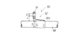
次に、図2を参照して、各竿管に取り付けられる前記ガイドの構造について説明する。ガイド30は、釣糸が挿通する環状のガイドリング31と、ガイドリング31を保持し、竿管40に装着される脚部32を有している。脚部32は竿管に沿うように延出部32aを有しており、この部分が、例えば糸巻き、糸止め、ビス等によって竿管40に固定される。この場合、脚部32は、図に示すような片足構造でも良いし、さらに穂先側に延出する延出部を有する両足構造でも良いが、図に示すように片足構造としておくことで、竿管のしなりを阻害することを防止でき、かつ釣糸の引掛かりを極力防止でき、投擲しやすく操作性の優れた投竿とすることができる。また、ガイドの軽量化が図れ、持ち重りを防止して、シャープに振れる投竿とすることができる。
【0013】
前記ガイドリング31の釣糸挿通部分の形状については限定されないが、円形状、楕円形状、略矩形状等で構成される。そして、ガイドリングの最小内口径をd(ここで最小内口径とは、リング状の最小の径部で釣糸のフレを効率良く防止することから、楕円のように長軸と短軸があるような構成の場合、短軸側を基準とする)、竿管表面からガイドリングの内周の最下部(長手方向においては、前記最小内口径が規定される位置)までの高さをh、ガイド取付位置における竿管の外径をDとした場合、図1のように装着される各ガイドは、以下のように構成されている。
【0014】
トップガイド3aの後部に位置する第1中間ガイド3bから元ガイド3iまでの各ガイドのガイドリングの最小内口径dを、各ガイド取付部の竿管の外径D以下に設定し、釣竿全長の1/2より前方に、少なくとも5個以上のガイドを配設しておく。このようなガイドの配置及び構成とすることにより、仕掛け投擲時の釣糸のブレが抑制されて糸抵抗を小さくでき、また、各ガイドリングの内口径が小さくなることから、竿管からガイドの内周面までの距離が相対的に短くなり、これによりねじりトルクの増大を防止でき、投擲時の方向の安定性、竿全体のしなりバランスの向上が図れる。
【0015】
なお、すべてのガイドが上記したD>dの関係を満たすことが好ましいが、一部(例えば、トップガイド又はトップガイドと第1中間ガイド3b,第2中間ガイド3c等の位置)において逆転していても良い。
【0016】
また、上記構成において、トップガイド3aの最小内口径を、第1中間ガイド3bの最小内口径と略同径、具体的には全く同径か、あるいは±0.5mmの範囲にしておくことが望ましい。このような構成とするのは、従来のトップガイドの最小内口径は、第1中間ガイドのそれよりも大きくしていたが、トップガイドの最小内口径を大きくするだけでは糸抵抗は減少しないため、むしろ、小型化、軽量化を図った方が持ち重りのしないシャープな調子の投竿とすることができるということに基づく。さらに、このような構成にすることで、竿先(トップガイド)に至るまでバランスのとれた投竿にすることができる。
【0017】
また、上記した構成において、さらに、元ガイド3iのガイドリング内周の最下面部での高さhを、元ガイド取付け位置の竿管外径寸法D以下にすると共に、元ガイド3iから第1中間ガイド3bまでの各ガイドの最下部高さ(前記hと同様に定義される)を順次低くすることが望ましい。このように構成することで、仕掛け投擲時のねじりトルクを確実に低減することができ、方向性が安定し、仕掛けの投擲時、あるいは魚が掛かった際にしなりバランスの向上が図れる。なお、最下部高さhを低くしすぎると、釣糸が竿管表面に当たって抵抗となるため、1/2D以上にすることが好ましい。
【0018】
図3は、ガイドの別の構成例を示す図である。このガイド50は、ガイドリング51の面(リング面)が穂先側に傾斜していると共に(竿管表面と傾斜したガイドリングとの角度をθとする)、竿管60に装着される片足の脚部52を有している。脚部52は竿管に沿うように延出部52aを有しており、この部分が、例えば糸巻き、糸止め、ビス等によって竿管60に固定される。しかし、移動可能又は分解可能に固定することもできる。
【0019】
このように、ガイドリングが穂先側に傾斜したガイドを用いることで、釣糸が引掛かりにくくなり、また、引掛かっても効果的に解くことができる。なお、θは、糸通過性と、糸絡みのそれぞれの限度を考慮して、10度〜60度の範囲に設定しておくことが好ましい。そして、このように構成されたガイドは、図1に示す投竿のすべての中間ガイド3b〜3hに用いても良いが、通常、釣糸は、実釣時において、穂先側のガイド部分(穂先から50cm程度)で最も絡みやすいことから、穂先側の中間ガイドの少なくとも3個以上に適用することが望ましい。
【0020】
また、図3に示すガイドにおいても、図2の構成と同様に、上述したD,d,hの関係を満たすように構成することが好ましい。
【0021】
次に、図1に示すような投竿1において、各竿管に装着される各ガイドの構成の具体例を以下の表1に示す。
【0022】
【表1】

上記した構成において、トップガイド及び第1中間ガイドから第6中間ガイドは、穂先竿管に配置することが望ましい。すなわち、釣竿の全長の1/2より前方に多数のガイドを配置することで、糸ブレが効果的に抑制されて、ねじりトルクの低減が図れ、操作性に優れた釣投竿にすることができる。また、第7中間ガイド及び元ガイドを中竿管に配設し、元竿管にガイドを配設しないことで、装着されたリールと元ガイドとの距離を長くすることができ、この結果、元ガイドへの釣糸導入角度が緩くなって釣糸とガイドとの抵抗が減ることから、仕掛けの飛距離の向上が図れる。また、元竿管にガイドを配設しないことで、釣糸の抵抗をより低減することができる
【0024】
【発明の効果】
以上のように、本発明によれば、仕掛けの投擲時にその方向性の安定が図れ、また、仕掛けの投擲時や魚が掛かった際に、しなりバランスが向上した投竿とすることができる。
【図面の簡単な説明】
【図1】本発明の投竿の全体構成を示す図。
【図2】図1に示す投竿に装着されるガイドの構成例を示す図。
【図3】図1に示す投竿に装着されるガイドの別の構成例を示す図。
【符号の説明】
1…投竿
3a…トップガイド
3b〜3h…中間ガイド
3i…元ガイド
30,50…ガイド
31,51…ガイドリング
40,60…竿管。[0001]
BACKGROUND OF THE INVENTION
The present invention relates to anchoring provided with an outer guide for guiding a fishing line.
[0002]
[Prior art]
Conventionally, in order to improve the flying distance of the device, there has been known a throwing device in which various measures are taken for a guide (outer guide) provided with a guide ring through which a fishing line is inserted. For example, Japanese Patent Laid-Open No. 8-294344 discloses a throw in which a first intermediate guide group from a guide at a predetermined position to an original guide and a second intermediate guide group from the guide at the predetermined position to a top guide are formed. Has been.
[0003]
As in this known throwing, in the conventional throwing, the guide is generally arranged such that the inner diameter of the guide ring is gradually reduced from the original guide toward the top guide. In this case, the guide ring is positioned as far as possible so that the fishing line discharged from the reel does not easily hit the rod (providing a high foot on the guide ring), or the resistance between the guide ring and the fishing line is reduced. Therefore, the inner diameter of the guide ring is made as large as possible.
[0004]
[Problems to be solved by the invention]
However, if the position of the guide (the position of the guide ring) is far from the rod (if the guide foot is high), the fishing line will hit the inner surface of the ring when throwing the device, and the rotational force (torsional torque) will be applied to the fishing rod. ), The direction of the throwing mechanism becomes difficult to stabilize, and even when a fish is caught, the fishing line hits the inner peripheral surface of the ring and a large force in the rotational direction acts on the fishing rod. Will fall.
[0005]
Also, if the inner diameter of the guide ring is large, fishing line blurring will increase when the device is thrown, and the directionality of the device to be thrown will be difficult to stabilize.
[0006]
The present invention has been made paying attention to the above-mentioned problems, and provides a throwing with improved stability when throwing or catching a fish while stabilizing the direction of the trick when throwing. The purpose is to do.
[0007]
[Means for Solving the Problems]
In order to solve the above-mentioned problem, the throwing of the present invention is such that the minimum inner diameter of the guide ring from the first intermediate guide to the original guide located at the rear portion of the top guide is equal to or smaller than the outer diameter of the guide tube of each guide mounting portion. In addition, at least five guides are arranged at a predetermined position outside the rod tube in front of half of the total length of the fishing rod, and the lowermost height of the guide from the original guide to the first intermediate guide is sequentially set. It is characterized by being lowered .
[0008]
As described above, since the minimum inner diameter of the guide ring from the first intermediate guide to the original guide is set to be equal to or smaller than the outer diameter of the guide tube of each guide mounting portion, the diameter of each guide ring is reduced. The fishing line blur during throwing is suppressed and the line resistance is reduced. Moreover, since the inner diameter of the guide ring is small, the distance from the soot tube to the inner peripheral surface of the guide ring is relatively short, and the lowermost height of the guide from the original guide to the first intermediate guide is sequentially reduced, As a result, an increase in torsional torque can be prevented, and stability in the direction during throwing and bending balance can be improved.
[0009]
DETAILED DESCRIPTION OF THE INVENTION
FIG. 1 is an overall view of throwing according to an embodiment of the present invention. The anchor 1 has a structure suitable for anchoring a relatively heavy weight such as No. 20 to 40 or a relatively light weight such as a lure. The anchor 1 is composed of a main rod 1a, a
[0010]
The anchor 1 includes, in order from the tip, a top guide 3a, a first
[0011]
The main casing 1a is provided with a
[0012]
Next, with reference to FIG. 2, the structure of the guide attached to each tub tube will be described. The
[0013]
The shape of the fishing line insertion portion of the
[0014]
The minimum inner diameter d of the guide ring of each guide from the first
[0015]
It is preferable that all the guides satisfy the above relationship of D> d. However, the guides are partially reversed (for example, the positions of the top guide or the top guide and the first
[0016]
In the above configuration, the minimum inner diameter of the top guide 3a may be substantially the same as the minimum inner diameter of the first
[0017]
Further, in the above-described configuration, the height h at the lowermost surface portion of the inner circumference of the guide ring of the original guide 3i is set to be equal to or smaller than the outer diameter D of the vertical tube at the original guide mounting position, and the first guide 3i to the first guide 3i. It is desirable to sequentially lower the lowest height (defined in the same manner as h) of each guide up to the
[0018]
FIG. 3 is a diagram illustrating another configuration example of the guide. In this
[0019]
In this way, by using the guide whose guide ring is inclined toward the tip, the fishing line is not easily caught and can be effectively unwound even if caught. Note that θ is preferably set in a range of 10 degrees to 60 degrees in consideration of the respective limits of thread passage and thread entanglement. The guide constructed in this way may be used for all the
[0020]
Also, the guide shown in FIG. 3 is preferably configured to satisfy the relationship of D, d, and h described above, similarly to the configuration of FIG.
[0021]
Next, in the anchor 1 as shown in FIG. 1, specific examples of the configuration of each guide mounted on each tub tube are shown in Table 1 below.
[0022]
[Table 1]
In the above-described configuration, it is desirable that the top guide and the first to sixth intermediate guides are arranged in the tip tube. That is, by arranging a large number of guides in front of half of the total length of the fishing rod, the yarn blur is effectively suppressed, the torsion torque can be reduced, and the fishing throwing rod excellent in operability can be obtained. it can. Further, by disposing the seventh intermediate guide and the original guide in the intermediate pipe and not providing the guide in the main pipe, the distance between the mounted reel and the original guide can be increased. Since the fishing line introduction angle to the former guide is reduced and the resistance between the fishing line and the guide is reduced, the flying distance of the device can be improved. In addition, the resistance of the fishing line can be further reduced by not providing a guide on the main rod. [0024]
【The invention's effect】
As described above, according to the present invention, the directionality can be stabilized at the time of throwing the device, and the throwing can be improved in balance when the device is thrown or when the fish is caught. .
[Brief description of the drawings]
FIG. 1 is a diagram showing an overall configuration of a throwing according to the present invention.
FIG. 2 is a diagram showing a configuration example of a guide attached to the anchor shown in FIG.
FIG. 3 is a view showing another configuration example of the guide attached to the anchor shown in FIG. 1;
[Explanation of symbols]
DESCRIPTION OF SYMBOLS 1 ... Throwing 3a ...
Claims (1)
Priority Applications (1)
| Application Number | Priority Date | Filing Date | Title |
|---|---|---|---|
| JP16844599A JP3716131B2 (en) | 1999-06-15 | 1999-06-15 | Throwing |
Applications Claiming Priority (1)
| Application Number | Priority Date | Filing Date | Title |
|---|---|---|---|
| JP16844599A JP3716131B2 (en) | 1999-06-15 | 1999-06-15 | Throwing |
Publications (2)
| Publication Number | Publication Date |
|---|---|
| JP2000354439A JP2000354439A (en) | 2000-12-26 |
| JP3716131B2 true JP3716131B2 (en) | 2005-11-16 |
Family
ID=15868256
Family Applications (1)
| Application Number | Title | Priority Date | Filing Date |
|---|---|---|---|
| JP16844599A Expired - Fee Related JP3716131B2 (en) | 1999-06-15 | 1999-06-15 | Throwing |
Country Status (1)
| Country | Link |
|---|---|
| JP (1) | JP3716131B2 (en) |
Families Citing this family (3)
| Publication number | Priority date | Publication date | Assignee | Title |
|---|---|---|---|---|
| JP4601363B2 (en) * | 2004-09-07 | 2010-12-22 | 株式会社シマノ | Thread guide mounting structure of the frame |
| JP5336431B2 (en) * | 2010-06-23 | 2013-11-06 | グローブライド株式会社 | Fishing rod with outside guide |
| JP2017070315A (en) * | 2017-01-27 | 2017-04-13 | グローブライド株式会社 | Fishing line guide, and fishing rod |
-
1999
- 1999-06-15 JP JP16844599A patent/JP3716131B2/en not_active Expired - Fee Related
Also Published As
| Publication number | Publication date |
|---|---|
| JP2000354439A (en) | 2000-12-26 |
Similar Documents
| Publication | Publication Date | Title |
|---|---|---|
| US9642346B2 (en) | Fishing line guide system | |
| JP3716131B2 (en) | Throwing | |
| JPH10290649A (en) | Casting rod for fishing | |
| US4429481A (en) | Spin-casting rod with lure jerking assembly | |
| US20030074827A1 (en) | Tangle free fishing pole | |
| US5598657A (en) | Inter-line fishing rod | |
| EP0832559A2 (en) | Telescopic type interline fishing rod | |
| KR200260385Y1 (en) | All purpose type reel fishing rod, this type can be use both for die casting and spinning reel | |
| US4798022A (en) | Combination fishhook and swivel | |
| JP3443098B2 (en) | Fishing rod with road line reel | |
| JP2538359Y2 (en) | Through fishing rod | |
| CN210610766U (en) | Magnetic type telescopic positioning hollow fishing rod | |
| JP2000312548A (en) | Fishhook | |
| JP2886091B2 (en) | Through fishing rod | |
| JP3240108B2 (en) | Spinning reel spool for fishing | |
| JP3211004U (en) | Squid fishing flip-up yaen | |
| GB2282946A (en) | Fishing rods | |
| JP2581407Y2 (en) | Through fishing rod | |
| JP2889215B2 (en) | Through fishing rod | |
| JP5363672B1 (en) | Fishing balance | |
| JP2000152735A (en) | Fishing rod | |
| JP2003230332A (en) | Fishing rod | |
| JP2895373B2 (en) | A series of through fishing rods | |
| JP2002051672A (en) | Rod for jigging | |
| JPWO2002054863A1 (en) | Fishing line assist guide device |
Legal Events
| Date | Code | Title | Description |
|---|---|---|---|
| A977 | Report on retrieval |
Free format text: JAPANESE INTERMEDIATE CODE: A971007 Effective date: 20050316 |
|
| A131 | Notification of reasons for refusal |
Free format text: JAPANESE INTERMEDIATE CODE: A131 Effective date: 20050322 |
|
| A521 | Written amendment |
Free format text: JAPANESE INTERMEDIATE CODE: A523 Effective date: 20050523 |
|
| TRDD | Decision of grant or rejection written | ||
| A01 | Written decision to grant a patent or to grant a registration (utility model) |
Free format text: JAPANESE INTERMEDIATE CODE: A01 Effective date: 20050823 |
|
| A61 | First payment of annual fees (during grant procedure) |
Free format text: JAPANESE INTERMEDIATE CODE: A61 Effective date: 20050829 |
|
| R150 | Certificate of patent or registration of utility model |
Free format text: JAPANESE INTERMEDIATE CODE: R150 |
|
| FPAY | Renewal fee payment (event date is renewal date of database) |
Free format text: PAYMENT UNTIL: 20110902 Year of fee payment: 6 |
|
| FPAY | Renewal fee payment (event date is renewal date of database) |
Free format text: PAYMENT UNTIL: 20110902 Year of fee payment: 6 |
|
| FPAY | Renewal fee payment (event date is renewal date of database) |
Free format text: PAYMENT UNTIL: 20120902 Year of fee payment: 7 |
|
| LAPS | Cancellation because of no payment of annual fees |