JP3715391B2 - Electronic level - Google Patents
Electronic level Download PDFInfo
- Publication number
- JP3715391B2 JP3715391B2 JP33708696A JP33708696A JP3715391B2 JP 3715391 B2 JP3715391 B2 JP 3715391B2 JP 33708696 A JP33708696 A JP 33708696A JP 33708696 A JP33708696 A JP 33708696A JP 3715391 B2 JP3715391 B2 JP 3715391B2
- Authority
- JP
- Japan
- Prior art keywords
- distance
- photoelectric conversion
- conversion means
- image
- electronic level
- Prior art date
- Legal status (The legal status is an assumption and is not a legal conclusion. Google has not performed a legal analysis and makes no representation as to the accuracy of the status listed.)
- Expired - Fee Related
Links
Images


Description
【0001】
【発明の属する技術分野】
本発明は、自動的に高さを求める電子レベルに関する。
【0002】
【従来の技術】
従来のこの種のものとして、例えば、特開平6−241789号公報により、略垂直に保持された棒状の標尺を視準し、標尺の画像を光電変換手段であるリニアセンサに結像させて電気信号に変換して視準位置の高さを自動的に求めるようにした電子レベルが知られている。尚、該電子レベルには接眼レンズの前方にシャッタが配設され、接眼レンズ側からの入光によってリニアセンサのS/N比が低下することを防止している。
【0003】
【発明が解決しようとする課題】
標尺までの距離が長くなると標尺の画像は細くなり、リニアセンサには標尺の画像の他に標尺の背景部分も結像される、標尺以外の背景部分がリニアセンサに結像されると標尺上のマークを識別しにくくなる。
【0004】
そこで本発明は、上記不都合に鑑み、標尺の背景の影響を受けない電子レベルを提供することを目的とする。
【0005】
【課題を解決するための手段】
前記課題を解決するために、本発明は、視準した標尺の画像を電気信号に変換する光電変換手段を備え、該光電変換手段が出力する画像データから視準位置の高さを自動的に求める電子レベルにおいて、上記標尺までの距離に応じて手動で移動される合焦レンズが備えられ、該合焦レンズの焦点移動に連動して移動するシャッタが設けられ、上記光電変換手段に結像される画像のうち、シャッタの移動によって、標尺までの距離の遠近にかかわらず標尺の背景部分のみを光電変換手段に対して遮蔽するようにしたことを特徴とする。
【0006】
上記光電変換手段として、具体的には、上下方向に並べられたラインセンサ、又は上下方向及び左右方向に並べられたCCD素子である。
【0007】
光電変換手段のラインセンサを上下方向に並べることにより、標尺の画像を縦方向に表示することができる。また、光電変換手段のCCD素子を上下方向及び左右方向に並べると共に、上記合焦レンズの焦点移動に連動してシャッタが移動することにより、光電変換手段には標尺部分の画像しか結像せず、背景部分の影響を除外することができる。
【0008】
尚、光学系を通じて光電変換手段に結像される標尺の画像の幅は標尺までの距離に応じて変化し、標尺が電子レベルに近い場合は標尺の画像の幅は比較的広くなり、標尺が遠ざかるに連れて標尺の画像の幅は狭くなる。従って、標尺までの距離が短い場合に合わせてシャッタをセットすると標尺までの距離が長くなるに連れ背景部分の画像が光電変換手段に結像される。逆に標尺が遠い場合に合わせてシャッタをセットすると標尺が近づいた場合に標尺の画像の一部しか利用できず、S/N比が悪くなる。
【0009】
そこで、標尺までの距離に連動して移動する合焦レンズの位置に応じてシャッタを移動させ、標尺までの距離の長短にかかわらず背景部分のみを遮断するようにした。
【0010】
【発明の実施の形態】
図1を参照して、1は電子レベルの望遠鏡部であり、先端の対物レンズ11の後方に合焦レンズ12が前後に移動自在の合焦筒13内に保持されている。合焦レンズ12の後方には望遠鏡部1の前後方向の傾きを補償するコンペセーター14と光軸に対して光を側方に分岐するビームスプリッタ15とが配置されている。ビームスプリッタ15で分岐されずに通過した光は焦点板16に到達し結像する。焦点板16には十字線が刻設されており、十字線上に結像された標尺Tを接眼レンズ17で目視するように構成されている。また、ビームスプリッタ15で分岐された光はビームスプリッタ15の側方に配設された光電変換手段である光電センサ2上に結像される。該光電センサ2としては、上下方向に沿った光の強弱を検出するラインセンサや、上下方向及び左右方向の光の強弱を検出するCCD素子を用いる。該光電センサ2で電気信号に変換された画像データは演算制御部3に出力される。該演算制御部3では光電センサ2からの画像データを基に標尺T上の視準位置の目盛りを読み取り、その結果を表示部31に表示する。
【0011】
上記合焦レンズ12は電子レベルから標尺Tまでの距離Dに応じて前後に移動し焦点板16及び光電センサ2上に標尺Tの画像をはっきりと結像させるものである。該合焦筒13にポテンショメータ4を取り付け、合焦筒13の前後の位置から距離Dを演算制御部3が検知し得るようにした。また、ビームスプリッタ15と光電センサ2との間に水平方向に開閉するシャッタ部5を取り付けた。
【0012】
図2に示すように、開閉駆動機構6は正逆回転自在なステッピングモータ61と芯ずれを吸収するカップリング62を介して連結された左右ねじ63とから構成されている。またシャッタ部5はガイド51に移動自在に保持された2枚のシャッタブレード52を有しており、両シャッタブレード52は上記左右ねじ63に螺合している。従って、ステッピングモータ61を回転させることにより両シャッタブレード52の間隔Wが増減する。該シャッタブレード52は演算制御部3によって駆動制御される開閉駆動機構6によって駆動され、シャッタ部5の開閉量が増減制御される。
【0013】
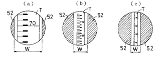
演算制御部3はポテンショメータ4からの位置信号により標尺Tまでの距離Dが短いことを検知すると両シャッタブレード52を離し間隔Wを拡げる。距離Dが短いと標尺Tの画像は大きくなるので間隔Wを拡げないと標尺Tの画像を間隔W内に収めることができない(図3(a)参照)。標尺Tが遠ざかり距離Dが増加するに従って標尺Tの画像が小さくなる。すると標尺Tの画像とシャッタブレード52との間から標尺Tの背景が光電センサ2に結像されるので、距離Dの増加に伴ってシャッタブレード52を相互に近付け間隔Wを狭めていく(図3(b)(c)参照)。距離Dと間隔Wとの関係はテーブルデータとして予め演算制御部3内に記憶されており、ポテンショメータ4からの位置信号が入力されると該テーブルデータから間隔Wを求め、更に該間隔Wになるようにステッピングモータ61を駆動する。
【0014】
ところで、標尺Tまでの距離Dに応じて合焦筒13を図示しないラックとピニオンとピニオンを回転させるつまみとにより手動で前後に移動させるが、距離Dに対する合焦筒13の位置の関係は、例えば図4に示すように、距離Dが短いと距離Dの変化に対する合焦筒13の移動量は大きいが、距離Dが長くなるにつれ距離Dの変化に対する合焦筒13の移動量は小さくなる。そして、距離Dが所定距離D1より長くなると距離Dの変化に対して合焦筒13の移動量はほぼ比例する。一方標尺Tの画像は距離Dの増加にほぼ比例して細くなる。第2の実施の形態として、図5に示すように合焦筒13にラック7を直接取り付けると共に両シャッタブレード52にラック74を各々取り付け、2個のピニオンギヤ71・72を介して両ラック7・7を連結した。但し、一方のシャッタブレード52については両ピニオンギヤ71・72の間にアイドルギヤ73を介在させ、一方のシャッタブレードの移動方向を他方のシャッタブレードの移動方向に対して逆になるようにした。該構成では両ピニオンギヤ71・72のギヤ比を変えることによってラック7の移動量に対するラック74の移動量を調節することができる。尚、図4に示したように、距離Dが短くなるにつれて合焦筒13の移動量が増加する。図5に示した構成では、距離Dが短くなると標尺Tの画像の幅が拡がる割合よりシャッタブレード52の間隔Wが広がる割合の方が大きくなる。ところが、距離Dが短くなり標尺Tの画像の幅が広くなるとシャッタがなくても光電センサ2には標尺Tの背景の画像が少ししか結像せず、従って、図5の構成であっても実用上問題となることはない。
【0015】
【発明の効果】
以上の説明から明らかなように、本発明は、標尺の画像の幅にあわせて標尺の背景をカットするシャッタを設けたので、背景の画像が標尺を光電変換手段(光電センサ)で認識する際の邪魔にならず、また逆光の場合であっても標尺の画像だけを光電変換手段に結像させるので標尺の画像のコントラストが曖昧になることがなく、測定エラーになる回数を減少させることができる。
【図面の簡単な説明】
【図1】本発明に係る電子レベルの構成を示す斜視図
【図2】開閉機構の構成を示すブロック図
【図3】光電センサ上の結像状態を示す図であって
(a)距離が短い場合を示す図
(b)距離が中程度の場合を示す図
(c)距離が長い場合を示す図
【図4】標尺までの距離に対する合焦筒の移動量を示す図
【図5】開閉機構の他の実施の形態を示す図
【符号の説明】
1 望遠鏡部
2 光電センサ(光電変換手段)
3 演算制御部
4 ポテンショメータ
5 シャッタ部
6 開閉駆動機構
T 標尺[0001]
BACKGROUND OF THE INVENTION
The present invention relates to an electronic level that automatically determines the height.
[0002]
[Prior art]
As this type of conventional one, for example, according to Japanese Patent Application Laid-Open No. 6-241789, a rod-shaped staff that is held substantially vertically is collimated, and an image of the staff is formed on a linear sensor that is a photoelectric conversion means for electric An electronic level is known which is converted into a signal to automatically obtain the height of the collimation position. Note that a shutter is provided in front of the eyepiece at the electronic level to prevent the S / N ratio of the linear sensor from being reduced by light incident from the eyepiece.
[0003]
[Problems to be solved by the invention]
When the distance to the standard is increased, the standard image becomes narrower, and the background part of the standard is imaged on the linear sensor in addition to the standard image. If the background part other than the standard is imaged on the linear sensor, It becomes difficult to identify the mark .
[0004]
SUMMARY OF THE INVENTION In view of the above problems, an object of the present invention is to provide an electronic level that is not affected by the background of a staff.
[0005]
[Means for Solving the Problems]
In order to solve the above-described problems, the present invention includes photoelectric conversion means for converting a collimated standard image into an electric signal, and automatically sets the height of the collimation position from the image data output from the photoelectric conversion means. A focusing lens that is manually moved according to the distance to the scale at a desired electronic level is provided, and a shutter that moves in conjunction with the movement of the focal point of the focusing lens is provided, and an image is formed on the photoelectric conversion means. among the images, by the movement of the shutter, characterized by being adapted to shield against the photoelectric conversion means only the background portion of the staff regardless perspective of the distance to the leveling rod.
[0006]
Specifically, the photoelectric conversion means is a line sensor arranged in the vertical direction, or a CCD element arranged in the vertical direction and the horizontal direction.
[0007]
By arranging the line sensors of the photoelectric conversion means in the vertical direction, the image of the standard can be displayed in the vertical direction. Further, with arranging the CCD elements of the photoelectric conversion means in the vertical and horizontal directions, by the shutter to move in conjunction with the focus movement of the focusing lens, an image of the leveling rod portion in the photoelectric conversion unit only without imaging The influence of the background part can be excluded.
[0008]
The width of the staff of the image formed on the photoelectric conversion means through the optical system varies depending on the distance to the leveling rod, if close staff within the electronic level width of staff of an image is relatively large, the staff As the distance increases, the width of the image of the scale becomes narrower. Accordingly, when the shutter is set in accordance with the case where the distance to the standard is short, an image of the background portion is formed on the photoelectric conversion means as the distance to the standard increases. On the other hand, if the shutter is set according to the case where the standard is far, only a part of the image of the standard can be used when the standard approaches, and the S / N ratio deteriorates.
[0009]
Therefore, the shutter is moved according to the position of the focusing lens that moves in conjunction with the distance to the staff, and only the background portion is blocked regardless of the length of the distance to the staff.
[0010]
DETAILED DESCRIPTION OF THE INVENTION
Referring to FIG. 1, reference numeral 1 denotes an electronic level telescope unit, and a focusing
[0011]
The focusing
[0012]
As shown in FIG. 2, the opening / closing drive mechanism 6 is composed of a stepping
[0013]
When the
[0014]
By the way, the focusing
[0015]
【The invention's effect】
As is clear from the above description, the present invention is provided with a shutter for cutting the background of the standard in accordance with the width of the standard image, so that when the background image recognizes the standard by the photoelectric conversion means (photoelectric sensor). In the case of backlighting, only the image of the scale is imaged on the photoelectric conversion means, so that the contrast of the scale image does not become ambiguous and the number of measurement errors can be reduced. it can.
[Brief description of the drawings]
FIG. 1 is a perspective view showing a configuration of an electronic level according to the present invention. FIG. 2 is a block diagram showing a configuration of an opening / closing mechanism. FIG. 3 is a diagram showing an imaging state on a photoelectric sensor. Figure (b) showing the case where the distance is short (b) Figure showing the case where the distance is medium (c) Figure showing the case where the distance is long [Figure 4] Figure showing the amount of movement of the focusing cylinder with respect to the distance to the staff Diagram showing another embodiment of mechanism [Explanation of symbols]
1 Telescope unit 2 Photoelectric sensor (photoelectric conversion means)
3
Claims (3)
Priority Applications (1)
| Application Number | Priority Date | Filing Date | Title |
|---|---|---|---|
| JP33708696A JP3715391B2 (en) | 1996-12-17 | 1996-12-17 | Electronic level |
Applications Claiming Priority (1)
| Application Number | Priority Date | Filing Date | Title |
|---|---|---|---|
| JP33708696A JP3715391B2 (en) | 1996-12-17 | 1996-12-17 | Electronic level |
Publications (2)
| Publication Number | Publication Date |
|---|---|
| JPH10176923A JPH10176923A (en) | 1998-06-30 |
| JP3715391B2 true JP3715391B2 (en) | 2005-11-09 |
Family
ID=18305310
Family Applications (1)
| Application Number | Title | Priority Date | Filing Date |
|---|---|---|---|
| JP33708696A Expired - Fee Related JP3715391B2 (en) | 1996-12-17 | 1996-12-17 | Electronic level |
Country Status (1)
| Country | Link |
|---|---|
| JP (1) | JP3715391B2 (en) |
Families Citing this family (1)
| Publication number | Priority date | Publication date | Assignee | Title |
|---|---|---|---|---|
| DE10008769C1 (en) * | 2000-02-24 | 2001-09-27 | Zsp Geodaetische Sys Gmbh | Processing signal for digital levelling gauge, using only pixel data provided by sensor elements within limited area of image sensor surface during adjustment of levelling gauge |
-
1996
- 1996-12-17 JP JP33708696A patent/JP3715391B2/en not_active Expired - Fee Related
Also Published As
| Publication number | Publication date |
|---|---|
| JPH10176923A (en) | 1998-06-30 |
Similar Documents
| Publication | Publication Date | Title |
|---|---|---|
| JP3174551B2 (en) | Focus adjustment lens position detector | |
| US4764016A (en) | Instrument for measuring the topography of a surface | |
| US3798449A (en) | Automatic microscope focussing device | |
| DE19549048B4 (en) | Telescope with inner focus | |
| JP2007025389A (en) | Zoom microscope and optional unit for zoom microscope | |
| JPH01245104A (en) | Microscope having device for measuring microscopic construction | |
| US4886347A (en) | Range-finding binocular | |
| US4340811A (en) | Focusing method and apparatus for use in an optical system | |
| EP1605229B1 (en) | Surveying apparatus | |
| GB2254704A (en) | Object distance measuring apparatus of camera | |
| US4174159A (en) | Exposure meter for photomicrography | |
| JP3715391B2 (en) | Electronic level | |
| CN101493376B (en) | Pentaprism combination ultralong focal-length measurement method and apparatus | |
| US3994558A (en) | Binocular microscope with improved monocular photographic and measuring capability using movable objective | |
| JPH0823616B2 (en) | Lens position control device | |
| US6321604B1 (en) | Electro-optical float position indicator | |
| US4279507A (en) | Spatial scanning means for a photometer | |
| US6269580B1 (en) | Motor-driven focusing apparatus of a sighting telescope | |
| US4633072A (en) | Focus apparatus for zoom lens system with distance detection | |
| US5805939A (en) | Camera arranged with a viewfinder system having an optical axis different from that of a distance measuring device | |
| US20010050764A1 (en) | Surveying instrument having an optical distance meter | |
| US3143589A (en) | Remote film viewer | |
| US4597649A (en) | Information display apparatus for ophthalmic slit lamps | |
| JP3421500B2 (en) | Surveying instrument with auto focus function | |
| US2910912A (en) | Binocular telescope with built-in rangefinder |
Legal Events
| Date | Code | Title | Description |
|---|---|---|---|
| A977 | Report on retrieval |
Free format text: JAPANESE INTERMEDIATE CODE: A971007 Effective date: 20050413 |
|
| A131 | Notification of reasons for refusal |
Free format text: JAPANESE INTERMEDIATE CODE: A131 Effective date: 20050419 |
|
| A521 | Written amendment |
Free format text: JAPANESE INTERMEDIATE CODE: A523 Effective date: 20050620 |
|
| TRDD | Decision of grant or rejection written | ||
| A01 | Written decision to grant a patent or to grant a registration (utility model) |
Free format text: JAPANESE INTERMEDIATE CODE: A01 Effective date: 20050726 |
|
| A61 | First payment of annual fees (during grant procedure) |
Free format text: JAPANESE INTERMEDIATE CODE: A61 Effective date: 20050825 |
|
| R150 | Certificate of patent or registration of utility model |
Free format text: JAPANESE INTERMEDIATE CODE: R150 |
|
| FPAY | Renewal fee payment (event date is renewal date of database) |
Free format text: PAYMENT UNTIL: 20080902 Year of fee payment: 3 |
|
| FPAY | Renewal fee payment (event date is renewal date of database) |
Free format text: PAYMENT UNTIL: 20090902 Year of fee payment: 4 |
|
| FPAY | Renewal fee payment (event date is renewal date of database) |
Free format text: PAYMENT UNTIL: 20100902 Year of fee payment: 5 |
|
| FPAY | Renewal fee payment (event date is renewal date of database) |
Free format text: PAYMENT UNTIL: 20100902 Year of fee payment: 5 |
|
| S533 | Written request for registration of change of name |
Free format text: JAPANESE INTERMEDIATE CODE: R313533 |
|
| FPAY | Renewal fee payment (event date is renewal date of database) |
Free format text: PAYMENT UNTIL: 20100902 Year of fee payment: 5 |
|
| R350 | Written notification of registration of transfer |
Free format text: JAPANESE INTERMEDIATE CODE: R350 |
|
| FPAY | Renewal fee payment (event date is renewal date of database) |
Free format text: PAYMENT UNTIL: 20100902 Year of fee payment: 5 |
|
| FPAY | Renewal fee payment (event date is renewal date of database) |
Free format text: PAYMENT UNTIL: 20100902 Year of fee payment: 5 |
|
| FPAY | Renewal fee payment (event date is renewal date of database) |
Free format text: PAYMENT UNTIL: 20110902 Year of fee payment: 6 |
|
| FPAY | Renewal fee payment (event date is renewal date of database) |
Free format text: PAYMENT UNTIL: 20110902 Year of fee payment: 6 |
|
| FPAY | Renewal fee payment (event date is renewal date of database) |
Free format text: PAYMENT UNTIL: 20120902 Year of fee payment: 7 |
|
| FPAY | Renewal fee payment (event date is renewal date of database) |
Free format text: PAYMENT UNTIL: 20120902 Year of fee payment: 7 |
|
| S531 | Written request for registration of change of domicile |
Free format text: JAPANESE INTERMEDIATE CODE: R313531 |
|
| FPAY | Renewal fee payment (event date is renewal date of database) |
Free format text: PAYMENT UNTIL: 20120902 Year of fee payment: 7 |
|
| R350 | Written notification of registration of transfer |
Free format text: JAPANESE INTERMEDIATE CODE: R350 |
|
| FPAY | Renewal fee payment (event date is renewal date of database) |
Free format text: PAYMENT UNTIL: 20120902 Year of fee payment: 7 |
|
| FPAY | Renewal fee payment (event date is renewal date of database) |
Free format text: PAYMENT UNTIL: 20120902 Year of fee payment: 7 |
|
| FPAY | Renewal fee payment (event date is renewal date of database) |
Free format text: PAYMENT UNTIL: 20120902 Year of fee payment: 7 |
|
| FPAY | Renewal fee payment (event date is renewal date of database) |
Free format text: PAYMENT UNTIL: 20130902 Year of fee payment: 8 |
|
| FPAY | Renewal fee payment (event date is renewal date of database) |
Free format text: PAYMENT UNTIL: 20130902 Year of fee payment: 8 |
|
| S531 | Written request for registration of change of domicile |
Free format text: JAPANESE INTERMEDIATE CODE: R313531 |
|
| FPAY | Renewal fee payment (event date is renewal date of database) |
Free format text: PAYMENT UNTIL: 20130902 Year of fee payment: 8 |
|
| R350 | Written notification of registration of transfer |
Free format text: JAPANESE INTERMEDIATE CODE: R350 |
|
| FPAY | Renewal fee payment (event date is renewal date of database) |
Free format text: PAYMENT UNTIL: 20130902 Year of fee payment: 8 |
|
| R250 | Receipt of annual fees |
Free format text: JAPANESE INTERMEDIATE CODE: R250 |
|
| R250 | Receipt of annual fees |
Free format text: JAPANESE INTERMEDIATE CODE: R250 |
|
| R250 | Receipt of annual fees |
Free format text: JAPANESE INTERMEDIATE CODE: R250 |
|
| LAPS | Cancellation because of no payment of annual fees |