JP3712839B2 - refrigerator - Google Patents
refrigerator Download PDFInfo
- Publication number
- JP3712839B2 JP3712839B2 JP19981497A JP19981497A JP3712839B2 JP 3712839 B2 JP3712839 B2 JP 3712839B2 JP 19981497 A JP19981497 A JP 19981497A JP 19981497 A JP19981497 A JP 19981497A JP 3712839 B2 JP3712839 B2 JP 3712839B2
- Authority
- JP
- Japan
- Prior art keywords
- refrigerator
- freezer compartment
- machine room
- cooler
- compartment
- Prior art date
- Legal status (The legal status is an assumption and is not a legal conclusion. Google has not performed a legal analysis and makes no representation as to the accuracy of the status listed.)
- Expired - Fee Related
Links
Images


Landscapes
- Cold Air Circulating Systems And Constructional Details In Refrigerators (AREA)
Abstract
Description
【0001】
【発明の属する技術分野】
本発明は、冷蔵庫に係り、最下段に冷凍室、その上段に野菜室を形成し、かつ冷凍室背部に冷却器等を収納するようにした冷蔵庫に関するものである。
【0002】
【従来の技術】
従来のこの種冷蔵庫は、外箱と内箱との間に発泡断熱材を充填し、かつ庫内を複数の温度帯に仕切って、各食品の温度に適した複数の貯蔵室を設けている。
従来のこの種冷蔵庫としては、例えば、特開平7−324853号公報記載のものが知られている。該公報記載の従来の冷蔵庫を図13ないし図15を参照して説明する。
図13は、従来の冷蔵庫の構造を示す縦断面図、図14は、図13の冷蔵庫の機械室を示す要部拡大図、図15は、図13の冷蔵庫における凝縮パイプの取付状態を示す説明図である。
【0003】
図13ないし図15に示す冷蔵庫は、最下段の冷凍室101の上段に野菜室102を形成し、この上に仕切板103を介して冷蔵室104を形成している。この冷蔵庫では、通常、野菜室102と冷凍室101とを区画する断熱仕切壁105を、冷蔵庫の庫内を形成する内箱106aと別体に形成している。
図において、107は除霜用管ヒータ、108は冷却器、109は冷気循環用ファン、110は冷気通路を示す。そして、上記除霜用管ヒータ107、冷却器108、冷気循環用ファン109は図に示す如く、冷凍室101と野菜室102の背壁部に除霜用管ヒータを下にして、図13の寸法H5の範囲に縦に積み上げたように取り付けられている。
【0004】
119は仕切板で、この仕切板119は、冷凍室101後部に配置された冷却器108等と冷凍室101とを区画する。
117は、冷蔵庫本体の下部背面に形成された機械室を示す。この機械室117内には圧縮機114等が設置されている。通常、上記圧縮機114の高さ寸法は150〜250mm位あるため、機械室117の天井面117aは図に示す如く、冷凍室101の底面101aのレベルより上方に位置している。
【0005】
前記除霜用管ヒータ107、冷却器108、冷気循環用ファン109は、機械室117の天井面117aの上方に位置するため、これら機器のユニットは、冷凍室101の間口における開口高さ寸法H4の範囲では、上記天井面117aが上方に位置する分足らなくなり、野菜室102の背部にまたがって配置されているのが現状である。したがって、前述した断熱仕切壁105等は複雑な形状の断熱仕切壁構造をとらざるを得なかった。
【0006】
図14において、115は、冷凍室101下部に形成された機械室117に連なる空間部に設置された除霜水蒸発用コンデンサであり、116は除霜水蒸発皿である。この除霜水蒸発皿116は、冷却器108に付いた霜の除霜を行ったときに出る除霜水を溜めるものである。すなわち、樋120で受けた除霜水は排水パイプ121を通って、この除霜水蒸発皿116に図に示す如く導かれるものである。
【0007】
【発明が解決しようとする課題】
図13ないし図15に示すように、野菜室102,冷凍室101間の断熱仕切壁105と、冷蔵庫の内箱106aとを別体に形成した従来の冷蔵庫にあっては、断熱仕切壁105と内箱106aとの当接部A,Bから水漏れを起こすという問題があった。このことは、断熱仕切壁105の構造が複雑になればなるほど問題となる。
また、圧縮機114の上方に除霜用管ヒータ107、冷却器108、冷気循環用ファン109等の機器を収納した従来の冷蔵庫にあっては、冷凍室101の内容積を確保するためにも、機械室117のスペースを小さくしなければならなかった。
【0008】
このため、凝縮器主部に係るメイン凝縮器を設置する場所を機械室117内に大きく確保することができないので、図15に示す如く、冷蔵庫の両側板に凝縮パイプ118を配設し、メイン凝縮器の代りとしていた。この凝縮器パイプ118はウレタン発泡により箱体106を構成する際に前もって別々の両側板の内側に取り付けておき、箱体形成後それらを接続し、さらに除霜水蒸発用コンデンサ115と接続するという面倒な手順を踏んでいた。
【0009】
以上の如く、除霜用コンデンサ115と凝縮パイプ118とはあらかじめ配管して置くことができないため、冷凍サイクルの組立性が悪いという問題がある。
また、金属製の側板および凝縮パイプ118がウレタンと接着固定されているので、冷蔵庫を廃棄する際に分別廃棄が困難となり、所謂廃家電対応ができなくなるという問題があった。
【0010】
さらに、凝縮パイプ118を止めて、これと同等の放熱量を有するメイン凝縮器を圧縮機114の両側空間に配設すると、該メイン凝縮器の取付性がスペース等の面から悪くなるという問題があった。
さらにまた、図14に示す如く、除霜水を受ける樋120と除霜水蒸発皿116との間に排水パイプ121が必要となる。この他、図14に示す如き構成の冷蔵庫にあっては、機械室117、特に圧縮機114が放熱する熱の影響を最も受けやすい所に冷蔵庫内で最も低温となる冷却器108が位置してしまうという問題があった。
【0011】
本発明は、上記従来技術の問題点を解決するためになされたもので、その第一の目的は、機械室のスペースを大きくし、凝縮器の収納性を向上して、機械室内だけで必要な凝縮器の放熱量を確保できるとともに、従来の凝縮パイプを廃止することにより、両側板と凝縮パイプの分離の手間がなくなり、廃家電対応の容易な冷蔵庫を提供することにある。
【0012】
また、本発明の第二の目的は、除霜用管ヒータ、冷却器、冷気循環用送風機の部組化を実現し、生産性を高めるとともに原価低減を図りうる冷蔵庫を提供することにある。
さらに、本発明の第三の目的は、野菜室と冷凍室とを区画する断熱仕切壁を複雑な形状とすることなしに、除霜用管ヒータ、冷却器、冷気循環用送風機を、上下に積み重ね方式で冷凍室背部に設置することのできる冷蔵庫を提供することにある。
【0013】
【課題を解決するための手段】
上記第一の目的を達成するために、本発明の冷蔵庫に係る第一の発明は、冷蔵庫の最下段に冷凍室、その上段に仕切壁を介して野菜室を形成し、冷蔵庫の背面および底部に機械室を形成してなる冷蔵庫において、前記機械室内の圧縮機と冷凍室背部に設けた冷却器とが高さ方向でオーバーラップする如く配設し、前記機械室は、当該機械室の天井の一部が前記仕切壁の厚みを投影する面内に位置するとともに、圧縮機の側部または上部のいずれかに凝縮器を収納できる空間領域を有するものである。
【0014】
すなわち、機械室内に設置された圧縮機と冷凍室背部に設けた冷却器とが高さ方向でオーバーラップする如く配設し、機械室天井の一部が仕切壁の厚みを投影する面内に位置するとともに、圧縮機の両側部あるいは上部に凝縮器を収納できる空間領域を設け、この機械室の空間に凝縮器を配設することによって、これと同等の放熱量を有する冷蔵庫の両側板に配設した従来の凝縮パイプを除去したものである。
【0015】
ここで、冷蔵庫底部の機械室には凝縮器のみを配設し、冷凍室背後の機械室に設置した圧縮機には、該圧縮機の上面と密着し、中央部に凸部を有する排水蒸発皿を設けたものである。
【0016】
また、上記第二の目的を達成するために、本発明の冷蔵庫に係る第二の発明は、冷蔵庫の最下段に冷凍室、その上段に仕切壁を介して野菜室を形成し、冷蔵庫の背面および底部に機械室を形成してなる冷蔵庫において、冷凍室背部に、下から除霜用管ヒータ、冷却器、冷気循環用送風機を積み上げるよう縦位置に配設するとともに、前記除霜用管ヒータが取付けられる樋を冷凍室底部に取付け、かつ、冷気循環用送風機上部を、冷凍室と野菜室とを仕切る断熱仕切壁下面に近接して配設するようにしたものである。
【0017】
すなわち、本発明の冷蔵庫は、冷凍室底面から除霜用管ヒータ、冷却器、冷気循環用送風機を縦に配設するとともに、除霜用管ヒータが取付けられる樋を冷凍室底部に取付け、かつ、冷気循環用送風機上部を、冷凍室と野菜室とを仕切る断熱仕切壁下面に近接して配設するようにしたものであるから、断熱仕切壁を複雑な形状にする必要がないことは勿論、使い易さが要求される野菜容器の大きさを十分に確保することができる。
特に、冷凍室の間口における開口高さ寸法と、除霜用管ヒータ、冷却器、冷気循環用送風機等の積み重ね品の高さ寸法とが近似していたとしても、その取付けを可能とすることができるものである。特に、樋に除霜用管ヒータを予めユニット化して所謂部組みしておくことにより、冷却器、冷気循環用送風機の取付けが容易になる。
【0018】
具体的構造として、除霜用管ヒータを取付ける樋を冷凍室底面より凹ませて配設するとともに、冷気循環用送風機上端は断熱仕切壁の凹みに対向させて設置するようにし、除霜用管ヒータ、冷却器、冷気循環用送風機を積み重ねた寸法を吸収するようにしている。こうすることにより、冷凍室の間口における開口高さ寸法より前記除霜用管ヒータ、冷却器、冷気循環用送風機の積み重ね寸法が大きくなつても収納を可能としたものである。
また、除霜用管ヒータ、冷却器、冷気循環用送風機を部組みした冷却箱を冷凍室背壁底部に配設したものであるから、この種冷蔵庫の生産性向上を図ることができる。
【0019】
本発明の冷蔵庫は、除霜用管ヒータ、冷却器、冷気循環用送風機等を部組みした冷却箱で冷凍室後方の内箱背面板を形成し、外箱と冷却箱との間に発泡断熱材を介在させるようにし、原価低減ならびに生産性の向上を図ったものである。
さらに、除霜用管ヒータ、冷却器、冷気循環用送風機を部組みした冷却箱と一体に樋および冷気ダクト等を形成し、部品点数の削減および生産性の向上を図るようにしたものである。
さらにまた、除霜用管ヒータ、冷却器、冷気循環用送風機を部組みした冷却箱に、温度調節器、温度ヒューズ等を組み付け、上記した効果を得るようにしたものである。
【0020】
さらに、上記第三の目的を達成するために、本発明の冷蔵庫に係る第三の発明は、冷蔵庫の最下段に冷凍室、その上段に仕切壁を介して野菜室を形成し、冷蔵庫の背面および底部に機械室を形成してなる冷蔵庫において、冷凍室後方に、下から除霜用管ヒータ、冷却器、冷気循環用送風機を積み上げるように縦位置に配設したときに、その積み上げ高さ寸法H1を、冷凍室底面と、冷凍室,野菜室を仕切る断熱仕切壁下面とで形成する冷凍室間口における開口高さ寸法H2にほぼ合わせたものである。
これにより、断熱仕切壁を複雑な形状に形成する必要がないことは勿論、使い易さが要求される野菜室容器の大きさを十分に確保することができ、かつ、内容積確保のため、野菜室扉を上方に上げる等ということのない冷蔵庫が得られる。
【0021】
具体的には、野菜容器を引出し扉に取り付けるとともに、その引出し扉の上面を床上760〜930mm前後とした。すなわち、この種冷蔵庫においては、野菜室の間口における開口高さが200〜350mm、冷凍室の間口における開口高さが350mm前後となる。この冷凍室の開口高さ寸法(縦寸法)H2内に、H1寸法の冷却器等を設置しようとするものである。
こうすることにより、冷却器等収納のために、断熱仕切壁を複雑な形状に形成する必要がなくなることは勿論、冷蔵室に次いで使用頻度の高い野菜室の使い勝手(例えば収納品の出し入れを容易となし、かつ、しまい込み等をなくすことができるものである。)の向上を図ることができる。
【0022】
また、本発明の冷蔵庫は、野菜室と冷凍室とを仕切る断熱仕切壁を、野菜室および冷凍室を構成する内箱で一体に形成することにより、断熱仕切壁と内箱との接合部シールをなくしたものである。
さらに、野菜室を構成する底面(断熱仕切壁上面)は背壁まで略フラットに形成するとともに、野菜容器底面も略フラットに形成するようにしたものであるから、野菜室の使い勝手が一段と向上するほか、収納量も増すという効果がある。
【0023】
【発明の実施の形態】
以下、本発明の各実施形態を図1ないし図12を参照して説明する。
始めに、図1ないし図5を参照して第二,第三の発明の実施形態を説明する。
図1は、本発明の一実施形態を示す冷蔵庫の要部縦断面図、図2は、図1のA部拡大図、図3は、図2に示す冷却器室の拡大図、図4は、図1の要部横断面図、図5は、本発明の他の実施形態を示す冷蔵庫の要部横断面図である。
【0024】
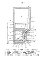
まず、図1を参照して本実施形態の冷蔵庫を説明する。
図1において、1は冷蔵庫本体で、この冷蔵庫本体1は、その内部に下から、冷凍室2、野菜室3、冷蔵室4を有している。換言すると、この冷蔵庫本体1は、野菜室3を冷蔵庫本体1の高さ方向の中心位置に形成しているものである。これは利用頻度の高い冷蔵室4、野菜室3を使い勝手の良い位置に設けようとする現われである。
【0025】
また、図1に示す冷蔵庫の冷凍室2,野菜室3を構成する容器2a,3aは後述する引出し扉の開閉に連動して引き出されるものである。
5は庫内を形成する内箱で、この内箱5は、冷凍室2,野菜室3間を区画する断熱仕切壁6と一体に形成されている。なお、前記断熱仕切壁6の野菜室3側は図1に示す如く平面状をなしている。
7は冷凍室扉で、この扉7は、前記容器2aをレール枠8をもって扉7側に取り付けている。したがって、冷凍室扉7の開閉に従って、容器2aは出入する。同様に、9は野菜室扉で、この扉9は、前記容器3aをレール枠10をもって扉9側に取り付けている。したがって、野菜室扉9の開閉に従って、容器3aは出入する。
【0026】
この野菜室扉9の上面9aから床面までの高さ寸法Hは、例えば、家庭の主婦などの使用者が取り扱い易い高さの760〜930mm前後に設定されている。したがって、この冷蔵庫においては、野菜室3の間口における開口高さが200〜350mm前後、冷凍室2の間口における開口高さが350mm前後となる。この冷凍室開口高さ寸法H2内に設定された除霜用管ヒータ12、冷却器11、冷気循環用送風機13を積み重ねた寸法H1は約350mm前後になるものであり、H1≒H2となっている。こうすることにより、従来の如く、冷却器11等を収納するために断熱仕切壁6を複雑な形状とする必要がなくなることは勿論、冷蔵室4に次いで利用頻度の高い野菜室3の使い勝手がよくなる。
【0027】
11は冷却器で、この冷却器11は、後述する圧縮機、メイン凝縮器等を伴って冷凍サイクルを構成する。
また、12は、前記冷却器11の下部で後述する樋に取り付けられた除霜用管ヒータ、13は、前記冷却器11の上部に設置された冷気循環用送風機、14は、前記除霜用管ヒータ12の下部に設けられた樋を示す。しかして、除霜用管ヒータ12、冷却器11、そして冷気循環用送風機13は、除霜用管ヒータを下にして上下に積み重ねられるようにして、縦位置に配置されている。
【0028】
16は、前記冷却器11等が設置されている冷却器室15と冷凍室2側とを区画する仕切板で、この仕切板16は、冷気循環用送風機13の吐出口(図示せず)を併せ形成しファンガードを兼ねている。
17は、冷凍室2の底部から背面にかけて形成された機械室で、この機械室17は、冷凍室2の内容積を減らす方向(冷凍室2側にくぼまされている)に形成されている。換言すると、機械室カバー18は冷凍室本体1寸法より後方にあまり出張らない寸法で取り付けられている。
【0029】
19は、機械室17内に設置された圧縮機、20は、その圧縮機19の上部に設置された凝縮器主部に係るメイン凝縮器、21は、冷蔵庫底部側機械室内に設置された除霜水蒸発用コンデンサー、22は、このコンデンサー21上に設置された除霜水蒸発皿である。この除霜水蒸発皿22内に溜められる除霜水は、コンデンサー21の熱を受けて蒸発促進されるものである。
【0030】
次に、前記圧縮機19、凝縮器20が取り付けられる機械室17について説明する。
図からも明らかなように、本発明を備えた冷蔵庫本体1の機械室17は、圧縮機19の上部にメイン凝縮器20を設置することができる高さを有している。すなわち、冷凍室2の背部に当たる断熱壁23の傾斜部23aの先端Pは断熱仕切壁6の厚みを投影する面内に位置し、機械室17の後板に係る機械室カバー18に接続されている。すなわち、この機械室17の天井面は後板側に向かって上向く傾斜部23aを形成している。そして、傾斜部23aの他方端は冷気循環用送風機13の設置対向部に接続されている。
【0031】
前記冷気循環用送風機13を設置するために、どうしても断熱壁を削る(薄肉とする)方向にある。傾斜部23aの下方端を前記冷気循環用送風機13の対向部にて接続することにより、この薄肉部の断熱厚をかせぐと共に、隅に形成される三角コーナー部(断熱仕切壁と傾斜部23a間で作る三角コーナー部)を冷気循環用送風機13の設置に活用することができる。
【0032】
通常、この種冷蔵庫本体1にあっては、冷凍室2の開口高さ寸法H2を350mm以上確保するのが普通である。したがって、断熱仕切壁6の位置は少なくとも冷凍室2の開口高さ寸法350mmプラス床面から冷凍室底壁23b迄の寸法H3(100〜150mm)以上となる。これは冷蔵庫本体1の高さ寸法にもよるが、通常冷蔵庫の高さ寸法の1/3〜1/4に当たる。換言すると、本実施形態を備えた機械室17は、それだけ大きく構成されているということである。この大きく形成された機械室17に、圧縮機19、メイン凝縮器20は上下に位置するよう取り付けられている。勿論、メイン凝縮器20は断熱壁23の傾斜部23aに接近することもある。
【0033】
次に、図2を参照して、除霜用管ヒータ12、樋14、除霜水蒸発皿22、圧縮機19等の関係について説明する。
まず、圧縮機19の高さ寸法は200mm以上あるのが普通である。したがって、ベース24の脚24a(据付床面)から冷凍室底面23b迄の寸法H3(100〜150mm)より高いのが普通である。それ故、圧縮機19は冷却器室15内の冷却器11と高さ方向でオーバーラップするよう設置されている。換言すると、冷却器11の下端は冷凍室底面23b近くに図に示す如く設置されているものである。そして、その冷却器11の下端下方に設置される除霜用管ヒータ12は樋14内に近接して配設されているものである。
【0034】
次に、冷気循環用送風機13と断熱仕切壁6との関係を説明する。
図2に示すように、本実施形態においては、除霜用管ヒータ12の上に冷却器11、冷気循環用送風機13を縦方向に積み上げるよう配置している。このため、縦方向に積み上げられる各部材の寸法が冷凍室2の開口高さ寸法H2が350mm前後位になれば仕切断熱壁に影響を与えることなく、冷凍室2の開口高さ寸法H2内での脱着が可能となるものである。
【0035】
このH2寸法内に先の除霜用管ヒータ12、冷却器11、冷気循環用送風機13を設置することが寸法的にも難しくなる場合が出てくる。このときには、除霜用管ヒータ12を、除霜水を受けるべく凹まされた樋14内、もしくは樋14に入る位接近させて配設するとよい。
一方、上部においては、断熱仕切壁6に冷気循環用送風機13の収納スペースを確保するための凹部6aを形成し、H2寸法内への除霜用管ヒータ12、冷却器11、冷気循環用送風機13の設置を可能にしている。このことは、後述する冷却箱30の場合も同じである。
【0036】
次に、図3を参照して、除霜用管ヒータ12、冷却器11、冷気循環用送風機13を取り付けている冷却箱30について説明する。
この冷却箱30は、前述した仕切板16と一緒になって冷却箱30を形成している。また、この冷却箱30は、図3に示す如く、樋14を一体に形成しているほか、冷気ダクト31等を一体に形成しても良い。しかして、上記冷却箱30は射出成形等により形成され、図には示してないが、除霜用管ヒータ12、冷却器11、冷気循環用送風機13を、冷却箱30に一体もしくは別体に設けた取付部(図示せず)にそれぞれねじ等をもって取り付け、固定されている。勿論、このときの冷却箱30の寸法はH1+αとなるので組み付け時には工夫を要する。また、先に説明した冷却器室15は、この冷却箱30内を指すものである。
【0037】
以上の如く構成することにより、除霜用管ヒータ12、冷却器11、冷気循環用送風機13、それに図には示してないが、温度調節器、温度ヒューズ等をユニットとして、冷蔵庫の組立ライン以外の所で冷却箱30内への組み付けが可能となるものである。
さらに、このようにユニットとして部組みされた冷却箱30を、図2に示す如く、内箱5の冷凍室2背部に組み込み、この冷却箱30と外箱29との間に発泡断熱材32を充填することにより、内箱5の真空成形難易度を軽減できるものである。
【0038】
また、本実施形態では、冷却箱30と樋14、冷気ダクト31等を一体のもので成形した例で示したが、これらは別体に成形しても本発明の効果は失われるものでない。逆に、H1≒H2であることを考えれば、図3に示す樋14は別体、すなわち、冷凍室底面23bに形成された取付用凹部に樋14を先に組み込むようにすれば、H1≒H2寸法の組み込みも容易とすることができる。勿論、このときには、除霜用管ヒータ12は樋14側に部組みした方が得策である。
【0039】
次に、図4を参照して機械室17の説明を行う。
図4において、25は機械室冷却用送風機、21は除霜水蒸発用コンデンサーで、このコンデンサー21が設置されている所は図に示す如く、冷蔵庫本体1の両側板1a,1bおよびダクト板26、底板27(図2参照)により囲まれた空間領域内である。この空間領域28は、機械室17に前記送風機25を介在して連通している。したがって、コンデンサー21を冷却すべく、冷蔵庫の前面側より矢印の如く空間領域28内に吸い込まれた空気は、除霜水蒸発用コンデンサー21を冷却したのち、機械室冷却用送風機25により圧縮機19に吹き付けられる。このことにより圧縮機19およびメイン凝縮器20(図1,2参照、図4では破線部)が冷却される。また、この過程において、除霜水蒸発皿22内の除霜水は除霜水蒸発用コンデンサー21の熱を受けて蒸発する。
【0040】
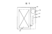
図5は、図1,2とは異なるメイン凝縮器20の設置例を示すものである。
図5に示す実施形態では、圧縮機19を機械室17の片側に寄せて収納している。メイン凝縮器20は、圧縮機19の隣に位置するもので、圧縮機高さより上部から下部に至り配設される。この収納構造は、特に巾の広い冷蔵庫(600mmを越える冷蔵庫)に有効である。
【0041】
本発明の実施形態は、以上説明した如き構成を有するものであるから、除霜用管ヒータ12、冷却器11、冷気循環用送風機13の冷凍室背部への設置は冷凍室2の間口高さ寸法H2を最大限に活用して収納できるものである。逆に言うと、上記除霜用管ヒータ12、冷却器11、冷気循環用送風機13の積み重ね高さ寸法H1を、冷凍室2の開口高さ寸法H2にほぼ合せることにより、断熱仕切壁6を従来のような複雑な形状にしなくても済むものである。
【0042】
また、このとき、樋14は、断熱壁23の底面23b内に埋め込まれ、除霜水は直接除霜水蒸発皿22内に排水される。特に、このときの樋14の排水口14a(図2で図示)を高温となる圧縮機19の手前に位置させることにより、該排水口14aは圧縮機19と熱交換する前の空気と熱交換することになるので、結果として樋14部を通しての冷凍室内への熱影響は小さくなるものである。
【0043】
さらに、冷凍サイクルを構成する主構成部品の内、冷却器11だけが冷蔵庫本体1内に設置されているので、メイン凝縮器20と冷却器11、冷却器11と圧縮機19の配管接続が従来問題となっていたが、本実施形態においては、冷却器11がメイン凝縮器20、圧縮機19等と比較的近くに位置することにより、配管接続に当たっては断熱壁23を貫通させれば容易にこれを接続することができるものである。
また、機械室17に十分なスペースを確保しているので、圧縮機19の上方にメイン凝縮器20の設置が可能となり、かつ、上記圧縮機19、メイン凝縮器20と熱交換した空気は機械室冷却用送風機25により、強制的に傾斜面に沿って機械室17外に排熱されるものである。
【0044】
さらに、冷気循環用送風機13部の断熱壁厚を十分確保する構造としたため、この部分からの冷凍室内への熱侵進も最少限にすることができることは勿論、冷却器11の奥行寸法より大きい寸法を有する冷気循環用送風機(送風機+モータの寸法)をそれ専用のくぼみ等を設けることなく、丁度断熱壁23の傾斜部23aで上記冷却器11よりも大きい寸法分を吸収できるものである。
【0045】
次に、図6ないし図12を参照して、第一の発明に相当する実施形態を説明する。
図6は、本発明のさらに他の実施形態に係る冷蔵庫の要部縦断面図、図7は、図6の冷蔵庫の要部横断面図、図8は、図7とは別の要部横断面図、図9は、図6の冷蔵庫に用いる補助凝縮器の説明図、図10は、図9の補助凝縮器に用いるフィンの平面図である。
【0046】
まず、図6を参照して第一の発明の冷蔵庫を説明する。図6において、図1に示した冷蔵庫と同一機器,部品は同一符号で示す。
図6に示す冷蔵庫は、冷凍室2の上段に野菜室3を形成し、冷凍室2,野菜室3間の断熱仕切壁6と冷蔵庫の箱体1Aとを一体に形成したものである。15は冷却器室で、この冷却器室15は、除霜用管ヒータ12、冷却器11、冷気循環用ファン13、および図示されていないが冷気通路を有する冷却器室15の周囲壁32により形成されている。この冷却器室15の周囲壁32は冷凍室2の背面に冷蔵庫の内箱5と別体に形成したものである。
【0047】
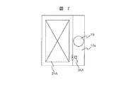
また、冷凍室2の背後部と底部には機械室17を設け、この機械室17には圧縮機19、凝縮器21A、除霜水蒸発皿22、および凝縮器用送風機25Aを配置している。
さらに、冷凍室2の後方に設置した冷却器室15と冷凍室2の背後に設けた機械室17の底部に設置した圧縮機19とは高さ方向でオーバーラップするように配設され、上記機械室17の天井の一部が略断熱仕切壁6の厚みを投影する面内に位置している。これにより、圧縮機19の上部あるいは図7に示す如く、圧縮機19の両側部に補助凝縮器を収納できる収納空間17aを有するものである。
【0048】
この場合、補助凝縮器33は、圧縮機19の両側部に分割して収納することになるので、冷凍サイクルの組立性は悪くなる。そこで、図8に示す如く、圧縮機19を機械室17の片側に寄せて収納し、補助凝縮器33を圧縮機19の側部に一括して配設し、この補助凝縮器33を冷蔵庫の両側板に配設した凝縮パイプと同等の放熱量を有するものとする。補助凝縮器は、図9、図10に示す如く、従来、冷蔵庫の両側板に配設した凝縮パイプと同等の放熱量を有するプレートフィン35を採用し、このプレートフィン35を補助凝縮器のパイプ34の1列の長さL=300mm、パイプピッチP=40mm、フィンピッチM=5mm、パイプ径d=6mm、パイプ本数N=4本、フィンの縦寸法a=30mm、フィンの横寸法b=30mmに設定したものである。
【0049】
これによって、従来冷蔵庫の側板に配設していた凝縮パイプを除去し、凝縮器21Aと補助凝縮器33とを、組立に当たってあらかじめ配線接続して置くことができ、冷凍サイクルの組立性を大幅に改善することができる。また、冷蔵庫の側板に固定された凝縮器パイプを除去したことによって、冷蔵庫廃棄時に起こる廃家電対応もできるように改善した。
【0050】
本発明のさらに他の実施形態を図11、図12に示す。
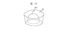
図11は、本発明のさらに他の実施形態に係る冷蔵庫の要部縦断面図、図12は、図11に示す冷蔵庫に用いる排水蒸発皿の斜視図である。図11において、図6と同一符号のものは先の実施形態と同等部であるから、その説明を省略する。
【0051】
図11に示す冷蔵庫では、冷凍室2の底部の機械室17に排水蒸発皿を配設することを止め、凝縮器21Aのみを配設し、その分、冷凍室2の間口における開口高さを増やし、冷凍室2の背後に設けた機械室17の中央にある圧縮機19を片側に寄せ、それによってできた空間領域に補助凝縮器33(図11には図示せず)を配設し、圧縮機19の上面に排水蒸発皿36を配設したものである。
【0052】
圧縮機19と排水蒸発皿36とは熱的接触をよくするために、図12に示すように、排水蒸発皿36の中央部に圧縮機19の上面と密着する凸部36aを形成したものである。この場合、圧縮機19の温度は凝縮器21Aの温度よりも高くなるので、排水蒸発皿36の温度も、従来の凝縮器に付けていた場合よりも高温になり、排水蒸発能力も向上するとともに、圧縮機19の放熱量も増すので冷蔵庫の冷却能力も向上する。
【0053】
しかして、断熱仕切壁6をフラットな構造にし、冷却器室15と冷凍室2の背後に設けた圧縮機19とを高さ方向でオーバーラップするようにすると、冷凍室2の奥行寸法が若干小さくなり、その分冷凍室2の内容積が減ることになるが、凝縮器21Aの上にあった排水蒸発皿を圧縮機19の上面に移すことにより、排水蒸発皿の高さ分だけ冷凍室2の開口高さ寸法を増やすことができる。これによって、冷凍室2の内容積を増やすことができ、トータルとして冷凍室2の内容積を確保できるようにしたものである。
【0054】
以上説明したように、第一の発明の冷蔵庫は、冷凍室2の上に断熱仕切壁6を介して野菜室3を有し、冷蔵庫背面底部に圧縮機19等を収納する機械室17を形成した冷蔵庫において、機械室17内の圧縮機19と冷凍室2背部に設けた冷却器等が高さ方向でオーバーラップする如く配設し、前記機械室17の天井の一部が断熱仕切壁6の厚みを投影する面内に位置するとともに、圧縮機19の両側部、あるいは上部に凝縮器を収納できる空間領域を有することによって、機械室17のスペースを大きくすることができ、凝縮器の収納性が向上し、圧縮機と凝縮器の配管作業性も向上した。
【0055】
また、冷蔵庫の両側板に配設した凝縮パイプと同等の放熱量を補助凝縮器33にもたせることによって、上記凝縮パイプを除去できるようにした。これによって、機械室17に圧縮機19、凝縮器21A、および補助凝縮器33を集約化することができ、機械室の部分組立が可能となり、冷蔵庫の組立を大幅に向上することができる。
さらに、凝縮パイプを廃止したことにより、両側板と凝縮パイプの分離の手間がなくなり、廃家電対応を容易にした。
【0056】
さらに、圧縮機19を機械室17の片側に配設し、その側部に補助凝縮器33を配設し、この補助凝縮器33をパイプ341列の長さL=300mm、パイプピッチP=40mm、フィンピッチM=5mm、パイプ径d=5mm、パイプ本数N=4本、フィン35の縦寸法a=30mm、フィン35の横寸法b=30mmに設定したことによって、補助凝縮器(縦300mm、横150mm、奥行40mm)を補助凝縮器の配設空間(縦500mm、横300mm、奥行100mm)に一体化して収納でき、圧縮機、凝縮器、および補助凝縮器を集約化することができ、冷蔵庫の組立作業を大幅に改善した。
【0057】
さらにまた、冷凍室底部の機械室17には凝縮器21Aのみを配設し、冷凍室背後の機械室17には、圧縮機19の上面と密着する中央部に凸部36aを有する排水蒸発皿36を配設したことによって、従来凝縮器の上に配設した排水蒸発皿の高さ分に担当する冷凍室2の開口高さを増やすことができ、トータルとして冷凍室2の内容積を確保した。
また、排水蒸発皿36の配設により圧縮機19の放熱がよくなり、その分冷蔵庫の冷却性能を改善した。
【0058】
【発明の効果】
以上詳細に説明したように、第一の発明によれば、機械室のスペースを大きくし、凝縮器の収納性を向上して、機械室内だけで必要な凝縮器の放熱量を確保できるとともに、凝縮パイプを廃止したことにより、両側板と凝縮パイプの分離の手間がなくなり、廃家電対応の容易な冷蔵庫を提供することができる。
【0059】
また、第二の発明によれば、除霜用管ヒータ、冷却器、冷気循環用送風機の部組化を実現し、生産性を高めるとともに原価低減を図りうる冷蔵庫を提供することができる。
さらに、第三の発明によれば、野菜室と冷凍室とを区画する断熱仕切壁を複雑な形状とすることなしに、上下に積み重ね方式で設けた除霜用管ヒータ、冷却器、冷気循環用送風機を、冷凍室背部に設置することのできる冷蔵庫を提供することができる。
【図面の簡単な説明】
【図1】本発明の一実施形態を示す冷蔵庫の要部縦断面図である。
【図2】図1のA部拡大図である。
【図3】図2に示す冷却器室の拡大図である。
【図4】図1の要部横断面図である。
【図5】本発明の他の実施形態を示す冷蔵庫の要部横断面図である。
【図6】本発明の他の実施形態に係る冷蔵庫の要部縦断面図である。
【図7】図6の冷蔵庫の要部横断面図である。
【図8】図7とは別の要部横断面図である。
【図9】補助凝縮器の説明図である。
【図10】図9の補助凝縮器に用いるフィンの平面図である。
【図11】本発明のさらに他の実施形態に係る冷蔵庫の要部縦断面図である。
【図12】図11に示す冷蔵庫に用いる排水蒸発皿の斜視図である。
【図13】従来の冷蔵庫の構造を示す縦断面図である。
【図14】図13の冷蔵庫の機械室を示す要部拡大図である。
【図15】図13の冷蔵庫における凝縮パイプの取付状態を示す説明図である。
【符号の説明】
1…冷蔵庫本体、1A…箱体、2…冷凍室、3…野菜室、5…内箱、6…断熱仕切壁、11…冷却器、12…除霜用管ヒータ、13…冷気循環用送風機、14…樋、15…冷却器室、16…仕切板、17…機械室、17a…収納空間、18…機械室カバー、19…圧縮機、20…メイン凝縮器、21…除霜水蒸発用コンデンサー、21A…凝縮器、22…除霜水蒸発皿、23…断熱壁、23a…傾斜部、25…冷却用送風機。25A…凝縮器用送風機、32…周囲壁、33…補助凝縮器、34…補助凝縮器のパイプ、35…プレートフィン、36…排水蒸発皿、36a…凸部。[0001]
BACKGROUND OF THE INVENTION
The present invention relates to a refrigerator, and relates to a refrigerator in which a freezer compartment is formed at the bottom, a vegetable compartment is formed at the top, and a cooler or the like is housed in the back of the freezer.
[0002]
[Prior art]
This type of conventional refrigerator is filled with a foam insulation between the outer box and the inner box, and the inside of the cabinet is divided into a plurality of temperature zones, and a plurality of storage rooms suitable for the temperature of each food are provided. .
As this kind of conventional refrigerator, for example, the one described in JP-A-7-324853 is known. A conventional refrigerator described in this publication will be described with reference to FIGS.
FIG. 13 is a longitudinal sectional view showing a structure of a conventional refrigerator, FIG. 14 is an enlarged view of a main part showing a machine room of the refrigerator of FIG. 13, and FIG. 15 is an explanatory view showing an attachment state of a condensation pipe in the refrigerator of FIG. FIG.
[0003]
In the refrigerator shown in FIG. 13 to FIG. 15, a
In the figure, 107 is a defrosting tube heater, 108 is a cooler, 109 is a cool air circulation fan, and 110 is a cool air passage. The
[0004]
117 shows the machine room formed in the lower back surface of the refrigerator main body. A
[0005]
Since the
[0006]
In FIG. 14,
[0007]
[Problems to be solved by the invention]
As shown in FIGS. 13 to 15, in the conventional refrigerator in which the heat
In addition, in a conventional refrigerator in which devices such as the
[0008]
For this reason, it is not possible to secure a large place in the
[0009]
As described above, since the
Further, since the metal side plate and the condensing pipe 118 are bonded and fixed to urethane, there is a problem that it becomes difficult to separate and dispose of the refrigerator when the refrigerator is discarded, and so-called waste home appliances cannot be handled.
[0010]
Furthermore, if the condenser pipe 118 is stopped and a main condenser having a heat release equivalent to this is disposed in the space on both sides of the
Furthermore, as shown in FIG. 14, a
[0011]
The present invention has been made to solve the above-mentioned problems of the prior art, and its first object is to increase the space in the machine room and improve the storage capacity of the condenser, and is necessary only in the machine room. Therefore, it is possible to provide a refrigerator that can easily handle waste home appliances by eliminating the need for separating the side plates and the condensation pipe by eliminating the conventional condensation pipe.
[0012]
The second object of the present invention is to provide a refrigerator that can realize a partial assembly of a defrosting tube heater, a cooler, and a cool air circulation blower to increase productivity and reduce costs.
Furthermore, the third object of the present invention is to provide a defrosting tube heater, a cooler, and a cool air circulation blower up and down without making the heat insulating partition wall that partitions the vegetable compartment and the freezer compartment complex. It is providing the refrigerator which can be installed in a freezer compartment back part by a stacking system.
[0013]
[Means for Solving the Problems]
In order to achieve the first object, the first invention according to the refrigerator of the present invention is to form a freezing room at the lowest stage of the refrigerator and a vegetable room through a partition wall at the upper stage of the refrigerator. In the refrigerator formed with a machine room, the compressor in the machine room and the cooler provided at the back of the freezer room are arranged so as to overlap in the height direction, and the machine room is a ceiling of the machine room. Is located in a plane where the thickness of the partition wall is projected, and has a space region in which the condenser can be accommodated in either the side portion or the upper portion of the compressor.
[0014]
That is, the compressor installed in the machine room and the cooler provided at the back of the freezer room are arranged so as to overlap in the height direction, and a part of the machine room ceiling is in a plane where the thickness of the partition wall is projected. Is located on both sides or top of the compressor, and a condenser is provided in the space of the machine room, thereby providing a side plate of the refrigerator having the same amount of heat radiation. A conventional condensing pipe is removed.
[0015]
Here, only the condenser is disposed in the machine room at the bottom of the refrigerator, and the compressor installed in the machine room behind the freezer compartment is in close contact with the upper surface of the compressor, and the drainage evaporation having a convex part at the center. A dish is provided.
[0016]
In order to achieve the second object, a second invention according to the refrigerator of the present invention is the rear surface of the refrigerator, wherein a freezer room is formed at the bottom of the refrigerator and a vegetable room is formed at the upper stage through a partition wall. In the refrigerator having a machine room formed at the bottom, the defrosting tube heater, the cooler, and the cool air circulation blower are arranged in a vertical position on the back of the freezing chamber from below, and the defrosting tube heater Is attached to the bottom of the freezer compartment, and the upper part of the cooling air circulation fan is disposed close to the lower surface of the heat insulating partition wall separating the freezer compartment and the vegetable compartment.
[0017]
That is, the refrigerator of the present invention has a defrosting tube heater, a cooler, and a cool air circulation blower arranged vertically from the bottom of the freezer compartment, and a basket to which the defrosting tube heater is attached is attached to the bottom of the freezer compartment, and The upper part of the cooling air circulation fan is arranged close to the lower surface of the heat insulating partition wall that partitions the freezer compartment and the vegetable compartment, so that the heat insulating partition wall does not need to have a complicated shape. The size of the vegetable container that requires ease of use can be secured sufficiently.
In particular, even if the opening height dimension at the entrance of the freezer compartment and the height dimension of the stacked product such as a defrosting tube heater, a cooler, and a fan for circulating cold air are approximated, it should be possible to install them. It is something that can be done. In particular, by installing the defrosting tube heater in a unit as a unit and so-called a partial assembly, it becomes easy to mount the cooler and the cool air circulation blower.
[0018]
As a specific structure, a defrosting pipe heater is installed with a trough for attaching a defrosting pipe heater recessed from the bottom of the freezer compartment, and the upper end of the cooling air circulation blower is opposed to the depression of the heat insulating partition wall. The dimensions of the stacked heater, cooler, and cooler circulation fan are absorbed. By doing so, even if the stacking dimensions of the defrosting tube heater, the cooler, and the cool air circulation blower are larger than the opening height dimension at the front of the freezer compartment, the housing can be accommodated.
Further, since a cooling box in which a defrosting tube heater, a cooler, and a cool air circulation blower are partly arranged is provided at the bottom of the freezer compartment back wall, the productivity of this type refrigerator can be improved.
[0019]
The refrigerator of the present invention forms an inner box back plate at the rear of the freezer compartment in a cooling box in which a defrosting tube heater, a cooler, a cooling air circulation fan, etc. are partly assembled, and foam insulation between the outer box and the cooling box It is intended to reduce costs and improve productivity by interposing materials.
Furthermore, a defroster and a cool air duct are formed integrally with a cooling box in which a defrosting tube heater, a cooler, and a cool air circulation blower are partly assembled to reduce the number of parts and improve productivity. .
Furthermore, a temperature regulator, a temperature fuse, etc. are assembled in a cooling box in which a defrosting tube heater, a cooler, and a cool air circulation blower are partially assembled to obtain the above-described effects.
[0020]
Furthermore, in order to achieve the third object, a third invention according to the refrigerator of the present invention is such that a freezer compartment is formed at the lowest stage of the refrigerator and a vegetable compartment is formed at the upper stage via a partition wall, and the rear surface of the refrigerator In a refrigerator formed with a machine room at the bottom, the stacking height when the defrosting tube heater, cooler, and cool air circulation blower are arranged in a vertical position behind the freezing room from below. Dimension H 1 The opening height dimension H at the freezer compartment front formed by the bottom of the freezer compartment and the lower surface of the heat insulating partition wall that partitions the freezer compartment and the vegetable compartment 2 It is almost matched to.
As a result, it is not necessary to form the heat insulating partition wall in a complicated shape, and it is possible to sufficiently ensure the size of the vegetable compartment container that is required to be easy to use, and to secure the internal volume, A refrigerator that does not raise the vegetable compartment door upward is obtained.
[0021]
Specifically, the vegetable container was attached to the drawer door, and the upper surface of the drawer door was about 760 to 930 mm above the floor. That is, in this type refrigerator, the opening height at the front of the vegetable compartment is 200 to 350 mm, and the opening height at the front of the freezer compartment is about 350 mm. Opening height dimension (vertical dimension) H of this freezer 2 Inside, H 1 It is intended to install a cooler with dimensions.
In this way, it is not necessary to form a heat insulating partition wall in a complicated shape for storing a cooler or the like, and it is easy to use the vegetable room that is most frequently used after the refrigerated room (for example, easy to put in and out the stored items). In addition, it is possible to eliminate trapping and the like.
[0022]
In the refrigerator of the present invention, the heat insulating partition wall for partitioning the vegetable compartment and the freezer compartment is integrally formed with the inner box constituting the vegetable compartment and the freezer compartment, so that the joint seal between the heat insulating partition wall and the inner box is sealed. It is a thing that lost.
Furthermore, the bottom of the vegetable compartment (upper surface of the heat insulating partition wall) is formed to be substantially flat up to the back wall, and the bottom of the vegetable container is also formed to be substantially flat, so that the convenience of the vegetable compartment is further improved. In addition, there is an effect of increasing the amount of storage.
[0023]
DETAILED DESCRIPTION OF THE INVENTION
Hereinafter, embodiments of the present invention will be described with reference to FIGS.
First, embodiments of the second and third inventions will be described with reference to FIGS.
1 is a longitudinal sectional view of a main part of a refrigerator showing an embodiment of the present invention, FIG. 2 is an enlarged view of a portion A in FIG. 1, FIG. 3 is an enlarged view of a cooler chamber shown in FIG. 1 is a cross-sectional view of a main part of FIG. 1, and FIG. 5 is a cross-sectional view of a main part of a refrigerator showing another embodiment of the present invention.
[0024]
First, the refrigerator of this embodiment is demonstrated with reference to FIG.
In FIG. 1, 1 is a refrigerator main body, and this refrigerator main body 1 has the
[0025]
Further, the
[0026]
The height dimension H from the upper surface 9a of the vegetable compartment door 9 to the floor surface is set to about 760 to 930 mm, which is easy for a user such as a housewife to handle. Therefore, in this refrigerator, the opening height in the front of the
[0027]
11 is a cooler, and this cooler 11 comprises a refrigerating cycle with a compressor, a main condenser, etc. which are mentioned later.
Also, 12 is a defrosting tube heater attached to a soot described below at the lower part of the cooler 11, 13 is a cool air circulation blower installed at the upper part of the cooler 11, and 14 is for the defrosting. 2 shows a gutter provided at the bottom of the
[0028]
[0029]
19 is a compressor installed in the
[0030]
Next, the
As is clear from the figure, the
[0031]
In order to install the
[0032]
Usually, in this kind of refrigerator main body 1, it is usual to secure the opening height dimension H2 of the
[0033]
Next, with reference to FIG. 2, the relationship between the defrosting
First, the height of the
[0034]
Next, the relationship between the
As shown in FIG. 2, in the present embodiment, the cooler 11 and the cool
[0035]
In some cases, it may be difficult to install the
On the other hand, in the upper part, a recess 6a for securing a storage space for the cool
[0036]
Next, the
The
[0037]
By constructing as described above, the
Further, as shown in FIG. 2, the
[0038]
In the present embodiment, the
[0039]
Next, the
In FIG. 4, 25 is a fan for cooling the machine room, 21 is a condenser for evaporating defrost water, and the
[0040]
FIG. 5 shows an installation example of the
In the embodiment shown in FIG. 5, the
[0041]
Since the embodiment of the present invention has the configuration as described above, the installation of the
[0042]
At this time, the
[0043]
Furthermore, since only the cooler 11 is installed in the refrigerator main body 1 among the main components constituting the refrigeration cycle, the piping connection between the
Further, since a sufficient space is secured in the
[0044]
Furthermore, since the heat insulation wall thickness of the cool
[0045]
Next, an embodiment corresponding to the first invention will be described with reference to FIGS.
6 is a longitudinal sectional view of a main part of a refrigerator according to still another embodiment of the present invention, FIG. 7 is a transverse sectional view of the main part of the refrigerator in FIG. 6, and FIG. 8 is a cross sectional view of the main part different from FIG. FIG. 9 is an explanatory view of an auxiliary condenser used in the refrigerator of FIG. 6, and FIG. 10 is a plan view of fins used in the auxiliary condenser of FIG.
[0046]
First, the refrigerator of 1st invention is demonstrated with reference to FIG. In FIG. 6, the same equipment and parts as those of the refrigerator shown in FIG.
The refrigerator shown in FIG. 6 has a
[0047]
Further, a
Furthermore, the
[0048]
In this case, since the
[0049]
As a result, the condensing pipe which has been conventionally provided on the side plate of the refrigerator can be removed, and the
[0050]
Yet another embodiment of the present invention is shown in FIGS.
FIG. 11 is a longitudinal sectional view of an essential part of a refrigerator according to still another embodiment of the present invention, and FIG. 12 is a perspective view of a drainage evaporating dish used for the refrigerator shown in FIG. In FIG. 11, the same reference numerals as those in FIG. 6 are the same as those in the previous embodiment, and the description thereof is omitted.
[0051]
In the refrigerator shown in FIG. 11, disposing the drainage evaporating dish in the
[0052]
In order to improve the thermal contact between the
[0053]
Thus, when the heat insulating partition wall 6 is made flat and the
[0054]
As described above, the refrigerator of the first invention has the
[0055]
Further, the condensation pipe can be removed by giving the auxiliary condenser 33 a heat radiation amount equivalent to that of the condensation pipe disposed on both side plates of the refrigerator. As a result, the
In addition, by eliminating the condensing pipe, there is no need to separate the two side plates and the condensing pipe, making it easier to deal with waste home appliances.
[0056]
Further, the
[0057]
Furthermore, only the
Moreover, the heat radiation of the
[0058]
【The invention's effect】
As explained in detail above, according to the first invention, it is possible to increase the space of the machine room, improve the stowability of the condenser, and ensure the necessary heat radiation of the condenser only in the machine room, By eliminating the condensing pipe, there is no need to separate the side plates and the condensing pipe, and it is possible to provide a refrigerator that can easily handle waste home appliances.
[0059]
In addition, according to the second aspect of the invention, it is possible to provide a refrigerator that can realize a partial assembly of a defrosting tube heater, a cooler, and a cool air circulation blower to increase productivity and reduce cost.
Furthermore, according to the third aspect of the present invention, the defrosting tube heater, the cooler, and the cold air circulation provided in a vertically stacked manner without making the heat insulating partition wall that partitions the vegetable compartment and the freezer compartment into a complicated shape. The refrigerator which can install the air blower for the freezer compartment back can be provided.
[Brief description of the drawings]
FIG. 1 is a longitudinal sectional view of an essential part of a refrigerator showing an embodiment of the present invention.
FIG. 2 is an enlarged view of a portion A in FIG.
FIG. 3 is an enlarged view of the cooler chamber shown in FIG. 2;
4 is a cross-sectional view of the main part of FIG.
FIG. 5 is a cross-sectional view of a main part of a refrigerator showing another embodiment of the present invention.
FIG. 6 is a longitudinal sectional view of a main part of a refrigerator according to another embodiment of the present invention.
7 is a cross-sectional view of a main part of the refrigerator in FIG.
FIG. 8 is a cross-sectional view of a main part different from FIG. 7;
FIG. 9 is an explanatory diagram of an auxiliary condenser.
10 is a plan view of fins used in the auxiliary condenser of FIG. 9. FIG.
FIG. 11 is a longitudinal sectional view of an essential part of a refrigerator according to still another embodiment of the present invention.
12 is a perspective view of a drainage evaporating dish used in the refrigerator shown in FIG.
FIG. 13 is a longitudinal sectional view showing the structure of a conventional refrigerator.
14 is an enlarged view of a main part showing a machine room of the refrigerator of FIG.
15 is an explanatory view showing a state of attachment of a condensation pipe in the refrigerator of FIG.
[Explanation of symbols]
DESCRIPTION OF SYMBOLS 1 ... Refrigerator main body, 1A ... Box body, 2 ... Freezer compartment, 3 ... Vegetable room, 5 ... Inner box, 6 ... Thermal insulation partition wall, 11 ... Cooler, 12 ... Defrosting tube heater, 13 ... Cooling air circulation fan , 14 ... 樋, 15 ... Cooler room, 16 ... Partition plate, 17 ... Machine room, 17a ... Storage space, 18 ... Machine room cover, 19 ... Compressor, 20 ... Main condenser, 21 ... For defrosted water evaporation Condenser, 21A ... condenser, 22 ... defrosted water evaporating dish, 23 ... heat insulating wall, 23a ... inclined part, 25 ... cooling fan. 25A ... Condenser blower, 32 ... Ambient wall, 33 ... Auxiliary condenser, 34 ... Pipe of auxiliary condenser, 35 ... Plate fin, 36 ... Waste water evaporating dish, 36a ... Projection.
Claims (13)
前記機械室内の圧縮機と冷凍室背部に設けた冷却器とが高さ方向でオーバーラップする如く配設した冷蔵庫。In the refrigerator formed by forming a freezer compartment at the bottom of the refrigerator, a vegetable compartment through a partition wall at the top, and forming a machine room on the back and bottom of the refrigerator,
A refrigerator arranged such that a compressor in the machine room and a cooler provided at the back of the freezer overlap in the height direction.
冷凍室背部に、下から除霜用管ヒータ、冷却器、冷気循環用送風機を積み上げるよう縦位置に配設するとともに、
前記除霜用管ヒータが取付けられる樋を冷凍室底部に取付け、かつ、冷気循環用送風機上部を、冷凍室と野菜室とを仕切る断熱仕切壁下面に近接して配設するようにしたことを特徴とする冷蔵庫。In the refrigerator formed by forming a freezer compartment at the bottom of the refrigerator, a vegetable compartment through a partition wall at the top, and forming a machine room on the back and bottom of the refrigerator,
Arranged in the vertical position so that the defrosting tube heater, cooler, cool air circulation blower are stacked from the bottom on the back of the freezer compartment,
The tub to which the defrosting tube heater is attached is attached to the bottom of the freezer compartment, and the upper part of the cooling air circulation fan is disposed close to the lower surface of the heat insulating partition wall that separates the freezer compartment and the vegetable compartment. Features a refrigerator.
冷凍室後方に、下から除霜用管ヒータ、冷却器、冷気循環用送風機を積み上げるように縦位置に配設したときに、その積み上げ高さ寸法H1を、冷凍室底面と、冷凍室,野菜室を仕切る断熱仕切壁下面とで形成する冷凍室間口における開口高さ寸法H2にほぼ合わせたことを特徴とする冷蔵庫。A freezer compartment is formed at the bottom of the refrigerator, and a vegetable compartment is formed at the top of the refrigerator via a partition wall. The freezer compartment is inserted and removed as the freezer compartment door is opened and closed, and machine rooms are formed on the back and bottom of the refrigerator. In the refrigerator
When the defrosting tube heater, the cooler, and the cool air circulation blower are arranged in a vertical position behind the freezer compartment, the stacked height dimension H 1 is set to the bottom of the freezer compartment, the freezer compartment, Refrigerator, characterized in that substantially match the opening height dimension H 2 in the refrigeration chamber frontage forming in the heat-insulating partition wall lower surface that partitions the crisper.
Priority Applications (1)
| Application Number | Priority Date | Filing Date | Title |
|---|---|---|---|
| JP19981497A JP3712839B2 (en) | 1997-07-25 | 1997-07-25 | refrigerator |
Applications Claiming Priority (1)
| Application Number | Priority Date | Filing Date | Title |
|---|---|---|---|
| JP19981497A JP3712839B2 (en) | 1997-07-25 | 1997-07-25 | refrigerator |
Publications (2)
| Publication Number | Publication Date |
|---|---|
| JPH1144478A JPH1144478A (en) | 1999-02-16 |
| JP3712839B2 true JP3712839B2 (en) | 2005-11-02 |
Family
ID=16414093
Family Applications (1)
| Application Number | Title | Priority Date | Filing Date |
|---|---|---|---|
| JP19981497A Expired - Fee Related JP3712839B2 (en) | 1997-07-25 | 1997-07-25 | refrigerator |
Country Status (1)
| Country | Link |
|---|---|
| JP (1) | JP3712839B2 (en) |
Families Citing this family (4)
| Publication number | Priority date | Publication date | Assignee | Title |
|---|---|---|---|---|
| JP2003042633A (en) * | 2001-07-26 | 2003-02-13 | Matsushita Refrig Co Ltd | Refrigerator |
| JP5369561B2 (en) * | 2008-07-14 | 2013-12-18 | パナソニック株式会社 | refrigerator |
| JP2013019623A (en) * | 2011-07-13 | 2013-01-31 | Panasonic Corp | Refrigerator |
| JP7470537B2 (en) * | 2020-03-11 | 2024-04-18 | 東芝ライフスタイル株式会社 | refrigerator |
-
1997
- 1997-07-25 JP JP19981497A patent/JP3712839B2/en not_active Expired - Fee Related
Also Published As
| Publication number | Publication date |
|---|---|
| JPH1144478A (en) | 1999-02-16 |
Similar Documents
| Publication | Publication Date | Title |
|---|---|---|
| US8033130B2 (en) | Refrigerator | |
| JP2575519B2 (en) | Combination refrigerator | |
| CN110375477B (en) | Refrigerator with refrigerating chamber at bottom of freezing chamber | |
| JP3712839B2 (en) | refrigerator | |
| JP2007064601A (en) | Refrigerator | |
| US2758449A (en) | Horizontal blower type refrigerated cabinet | |
| US6014868A (en) | Refrigerator with improved cold air supply structure | |
| EP0126521B1 (en) | Refrigerator | |
| CN110375486B (en) | Refrigerator and heat dissipation control method thereof | |
| JPH1144479A (en) | Refrigerator | |
| US20210207871A1 (en) | Entrance refrigerator and storage system for house entrance having the same | |
| JP3510770B2 (en) | refrigerator | |
| JP3721705B2 (en) | refrigerator | |
| JP3420109B2 (en) | refrigerator | |
| CN114076460A (en) | Refrigerator capable of increasing capacity of bottom storage space | |
| JP2983824B2 (en) | Horizontal refrigerator | |
| CN210625070U (en) | Refrigerator with optimized evaporator fixing structure | |
| CN219913612U (en) | Refrigerator with a refrigerator body | |
| JPH09243227A (en) | Cooling storage chamber | |
| JPS5818144Y2 (en) | refrigerator | |
| JP4156952B2 (en) | Cooling storage | |
| JP2006046791A (en) | Refrigerator | |
| JPH10205996A (en) | Thermal insulation box of cooling refrigerator | |
| JP2003097883A (en) | Refrigerator | |
| JPH0629654Y2 (en) | Freezer storage |
Legal Events
| Date | Code | Title | Description |
|---|---|---|---|
| A521 | Written amendment |
Free format text: JAPANESE INTERMEDIATE CODE: A523 Effective date: 20040714 |
|
| A621 | Written request for application examination |
Free format text: JAPANESE INTERMEDIATE CODE: A621 Effective date: 20040714 |
|
| RD02 | Notification of acceptance of power of attorney |
Free format text: JAPANESE INTERMEDIATE CODE: A7422 Effective date: 20040714 |
|
| A131 | Notification of reasons for refusal |
Free format text: JAPANESE INTERMEDIATE CODE: A131 Effective date: 20050419 |
|
| A521 | Written amendment |
Free format text: JAPANESE INTERMEDIATE CODE: A523 Effective date: 20050601 |
|
| RD02 | Notification of acceptance of power of attorney |
Free format text: JAPANESE INTERMEDIATE CODE: A7422 Effective date: 20050601 |
|
| TRDD | Decision of grant or rejection written | ||
| A01 | Written decision to grant a patent or to grant a registration (utility model) |
Free format text: JAPANESE INTERMEDIATE CODE: A01 Effective date: 20050809 |
|
| A61 | First payment of annual fees (during grant procedure) |
Free format text: JAPANESE INTERMEDIATE CODE: A61 Effective date: 20050818 |
|
| R150 | Certificate of patent or registration of utility model |
Free format text: JAPANESE INTERMEDIATE CODE: R150 |
|
| FPAY | Renewal fee payment (event date is renewal date of database) |
Free format text: PAYMENT UNTIL: 20080826 Year of fee payment: 3 |
|
| FPAY | Renewal fee payment (event date is renewal date of database) |
Free format text: PAYMENT UNTIL: 20090826 Year of fee payment: 4 |
|
| FPAY | Renewal fee payment (event date is renewal date of database) |
Free format text: PAYMENT UNTIL: 20100826 Year of fee payment: 5 |
|
| FPAY | Renewal fee payment (event date is renewal date of database) |
Free format text: PAYMENT UNTIL: 20100826 Year of fee payment: 5 |
|
| FPAY | Renewal fee payment (event date is renewal date of database) |
Free format text: PAYMENT UNTIL: 20110826 Year of fee payment: 6 |
|
| FPAY | Renewal fee payment (event date is renewal date of database) |
Free format text: PAYMENT UNTIL: 20120826 Year of fee payment: 7 |
|
| LAPS | Cancellation because of no payment of annual fees |