JP3712057B2 - Color conversion table creation method, color conversion table creation device, color conversion table creation program, color conversion device, and printing device - Google Patents
Color conversion table creation method, color conversion table creation device, color conversion table creation program, color conversion device, and printing device Download PDFInfo
- Publication number
- JP3712057B2 JP3712057B2 JP2001261746A JP2001261746A JP3712057B2 JP 3712057 B2 JP3712057 B2 JP 3712057B2 JP 2001261746 A JP2001261746 A JP 2001261746A JP 2001261746 A JP2001261746 A JP 2001261746A JP 3712057 B2 JP3712057 B2 JP 3712057B2
- Authority
- JP
- Japan
- Prior art keywords
- color space
- coordinates
- color
- conversion
- target
- Prior art date
- Legal status (The legal status is an assumption and is not a legal conclusion. Google has not performed a legal analysis and makes no representation as to the accuracy of the status listed.)
- Expired - Fee Related
Links
Images


Classifications
-
- H—ELECTRICITY
- H04—ELECTRIC COMMUNICATION TECHNIQUE
- H04N—PICTORIAL COMMUNICATION, e.g. TELEVISION
- H04N1/00—Scanning, transmission or reproduction of documents or the like, e.g. facsimile transmission; Details thereof
- H04N1/46—Colour picture communication systems
- H04N1/56—Processing of colour picture signals
- H04N1/60—Colour correction or control
- H04N1/603—Colour correction or control controlled by characteristics of the picture signal generator or the picture reproducer
- H04N1/6033—Colour correction or control controlled by characteristics of the picture signal generator or the picture reproducer using test pattern analysis
-
- H—ELECTRICITY
- H04—ELECTRIC COMMUNICATION TECHNIQUE
- H04N—PICTORIAL COMMUNICATION, e.g. TELEVISION
- H04N1/00—Scanning, transmission or reproduction of documents or the like, e.g. facsimile transmission; Details thereof
- H04N1/46—Colour picture communication systems
- H04N1/56—Processing of colour picture signals
- H04N1/60—Colour correction or control
- H04N1/6016—Conversion to subtractive colour signals
- H04N1/6019—Conversion to subtractive colour signals using look-up tables
Landscapes
- Engineering & Computer Science (AREA)
- Multimedia (AREA)
- Signal Processing (AREA)
- Facsimile Image Signal Circuits (AREA)
- Color Image Communication Systems (AREA)
- Color, Gradation (AREA)
- Image Processing (AREA)
Description
【0001】
【発明の属する技術分野】
本発明は、色変換テーブル作成方法、色変換テーブル作成装置、色変換テーブル作成プログラム、色変換装置および印刷装置に関する。
【0002】
【従来の技術】
ディスプレイやプリンタ等の画像機器は、通常3色の色成分を階調値で表現したカラー画像データを使用して任意の色を表現している。例えば、R(レッド),G(グリーン),B(ブルー)の3色を使用したRGB表色系やC(シアン),M(マゼンタ),Y(イエロー)3色を使用したCMY表色系等種々の表色系を使用している。この表色系は一般に画像機器固有の機器独立色であるので、種々の画像機器間で同じ画像を同じ色で出力可能にするために表色系間の対応関係を規定したLUT(ルックアップテーブル)が用いられている。当該LUTにおいては、入力側画像機器の表色系と出力側画像機器の表色系との対応関係を規定したものや出力側画像機器の表色系と絶対色空間との対応関係を規定したものがある。
【0003】
印刷装置におけるLUTは通常M3個(MはLUTの各成分のグリッド数)の座標にて対応関係を規定する必要があり、総ての点について測色器で測定するのは非現実的なため、N3個(M>N)の座標点をサンプルデータとしてM3個の座標点を規定している。例えば、Luv座標値をCMY座標値と対応づけるに当たり、所定のCMY値に基づいて印刷したN3個のパッチを測色器で測定しLuv座標値を得るとともに、得られた対応関係を使用して体積補間等の線形補間演算を行い、任意のM3個のLuv座標値に対するCMY座標値を算出していた。
【0004】
【発明が解決しようとする課題】
上述した従来の色変換プログラムでは、以下のような課題があった。
すなわち、上記印刷装置によってサンプルの色パッチを印刷するため、CMY座標値はCMY表色系において立方格子点の座標値を選定することができるものの、測色結果によって対応づけられるLuv表色系等の均等知覚色空間の座標値が形成する格子点は一般に歪んでいる。上記体積補間演算において立方格子点内の任意座標を歪んだ格子点内の任意座標に変換する際には高精度で変換可能であるが、歪んだ格子点内の任意座標を高精度で立方格子点内の任意座標に変換するためには非常に多くの格子点が必要となり、上記N3個程度の座標点では不十分である。従って、上述のようにして作成されたLUTの精度は高いとは言えない。
【0005】
実際の印刷に際しては任意の座標値を当該LUTに規定された座標値にて補間演算することによって算出するので、印刷時に高精度で色変換を行うことができない。具体的には、表色空間のある領域が周りの領域と比較して局所的に低精度となる現象を避けることができず、印刷結果にトーンジャンプを生じさせてしまう。また、この手法においては種々の印刷装置の機種総てに対して一定レベルの高精度を担保することができず、ある機種での色変換が突出して低精度となるようなことがある。
本発明は、上記課題にかんがみてなされたもので、表色空間の全域で高精度の色変換を可能にするとともに、変換精度に機種依存性を生じさせることのない色変換テーブルを生成可能な色変換テーブル作成方法、色変換テーブル作成装置、色変換テーブル作成プログラム、色変換装置および印刷装置の提供を目的とする。
【0006】
【課題を解決するための手段】
上記目的を達成するため、請求項1にかかる発明は、予め取得される所定数のサンプルデータによって規定された第1色空間と第2色空間との対応関係に基づいて当該第1色空間と第2色空間との対応関係を規定する多数のデータを含む色変換テーブルデータを作成する色変換テーブル作成方法であって、第1色空間内の任意座標と第2色空間内の任意座標とを相互に変換するに当たり、上記サンプルデータに基づく変換によって上記第1色空間から第2色空間への変換より上記第2色空間から第1色空間への変換の方が高精度に変換可能な状況において、上記対応関係が規定される対象のターゲット座標を上記第1色空間内で決定するターゲット座標決定工程と、上記第2色空間内で変換対象となる座標を決定する変換対象座標決定工程と、上記サンプルデータに基づいて上記変換対象となる座標を第1色空間内の対応座標に変換する変換工程と、同変換工程にて変換された第1色空間内の対応座標と上記ターゲット座標とのずれ量が小さくなるように上記変換対象座標決定工程と変換工程とを繰り返し試行する試行工程と、当該試行工程において上記ずれ量が所定のしきい値以下になったときに上記変換対象となった第2色空間内の座標と上記ターゲット座標とを対応づけて色変換テーブルデータを生成する色変換テーブルデータ生成工程とを具備する構成としてある。
【0007】
上記のように構成した請求項1にかかる発明においては、予め取得される所定数のサンプルデータによって規定された第1色空間と第2色空間との対応関係に基づいて当該第1色空間と第2色空間との対応関係を規定する多数のデータを含む色変換テーブルデータを作成する。ここで作成されるデータは、第1色空間から第2色空間へ高精度で変換可能にするデータであり、上記サンプルデータに基づく変換によって上記第1色空間から第2色空間への変換より上記第2色空間から第1色空間への変換の方が高精度に変換可能な状況において以下の工程に沿って生成される。
【0008】
まず、ターゲット座標決定工程において色変換テーブルとして対応関係が規定される対象のターゲット座標が上記第1色空間内で決定され、変換対象座標決定工程において上記第2色空間内で変換対象となる座標が決定される。変換工程においては、上記サンプルデータに基づいて上記変換対象となる座標を第1色空間内の対応座標に変換する。上述のようにこの変換は高精度に変換可能である。試行工程では当該変換工程にて変換された第1色空間内の対応座標と上記ターゲット座標とのずれ量が小さくなるように上記変換対象座標決定工程と変換工程とを繰り返し試行する。すなわち、試行の繰り返しによって通常は第1色空間内でのずれ量が徐々に小さくなっていく。そして、色変換テーブルデータ生成工程では当該試行工程において上記ずれ量が所定のしきい値以下になったときに上記変換対象となった第2色空間内の座標と上記ターゲット座標とを対応づけて色変換テーブルデータを生成する。
【0009】
すなわち、本発明においては第2色空間内の座標を第1色空間内の座標へ変換するとともに当該変換後の座標がターゲット座標と所定のしきい値以下に接近するまで試行を繰り返す。従って、このしきい値を充分小さくすることにより、試行後の第2色空間内の座標と第1色空間内の座標とは同色とみなすことができ、この時点で両者を対応づけることによって両色空間の座標を高精度に対応づけることができる。尚、しきい値を使用した判別には、ずれ量と所定のしきい値とを直接的に比較して判別を行う構成の他、ずれ量を第1色空間を構成する軸に沿った成分で表現し当該成分が所定のしきい値以下になっているか否かを判別する構成等も採用可能である。ここで、両色空間の座標が高精度に対応づけられるのは、上記変換工程にて第2色空間から第1色空間へ高精度に座標変換可能であることに基づいている。すなわち、変換後の座標とターゲット座標とのずれが所定値以下になったとしても変換精度が低精度であれば第2色空間の座標とターゲット座標とが同色であるとみなすことはできない。変換後の座標とターゲット座標とが第1色空間内で非常に接近していたとしても精度誤差に起因して偶然接近しているだけと言うことも考えられるからである。
【0010】
また、ターゲット座標と第2色空間との対応関係を規定するにあたり、上記試行を繰り返すことによって、低精度の変換である第1色空間から第2色空間への変換を実施することなく色変換テーブルデータを生成することができ、任意のターゲット座標に関して一度もターゲット座標を低精度変換で変換する必要がない。さらに、試行によって第2色空間内の座標を徐々に目標に近づけるので、任意のターゲット座標についてその第1色空間の位置やサンプルデータの配置に影響を受けることなく、第2色空間の対応座標を求めることができる。従って、一般のLUTに必要なM3個の座標を容易に得ることができる。さらに、試行によって第2色空間内の座標を移動させるので上記サンプルデータの一部のデータが誤っていたとしても、上記工程で既に生成した色変換テーブルデータをサンプルデータとして使用していくことによって徐々に正確な対応関係を規定した色変換テーブルデータが増加し、最終的には総ての座標で高精度に対応関係を規定した色変換テーブルデータとすることができる。
【0011】
ここで、色変換による精度に関してはサンプルデータに基づいて上記第1色空間から第2色空間への変換より上記第2色空間から第1色空間への変換の方が高精度に変換可能であればよい。すなわち、第2色空間から第1色空間への変換が高精度に実行可能であれば上記ターゲット座標を第2色空間の座標へ直接変換するよりも上記試行工程を経た方が結果として高精度の対応関係を規定することができる。両変換の精度差が大きいほど本発明を実施するメリットが増大する。この変換手法としては特に限定されないが、補間演算を想定すると上述のように変換精度に差が生ずる状況となりやすい。すなわち、第2色空間の座標で表現された色を所定の画像機器で出力し、当該出力色を測色して第1色空間内の座標を得る場合、これらの対応関係がサンプルデータとなるが、画像機器でいずれの色を出力させるのかは通常容易に制御できる。
【0012】
そこで、第2色空間で立方格子を構成する座標の色を出力させれば、対応色は一般的に第1色空間で立方格子とならないが、補間演算によって立方格子内の座標を非立方格子内の座標に変換するのは非常に容易、すなわち高精度に実施可能であるが、逆変換は容易ではなく一般に低精度となる。従って、かかる状況において本発明を適用すると、低精度の変換をすることなく高精度に両空間の対応関係を規定することができるので、非常に高精度で色変換可能な色変換テーブルデータを生成することができる。また、上記非立方格子内の座標を立方格子内の座標に変換する低精度の変換手法を実施する場合には、この非立方格子の形状によって変換精度に局所的なばらつきが生じ易く、変換精度の画像機器機種依存性の原因となるが、本発明では高精度の変換を使用して試行するので、生成後の色変換テーブルデータによる色変換精度に局所的なばらつきが生じることがなく、機種依存性が生じることもない。
【0013】
ターゲット座標決定工程においては、色変換テーブルデータ生成対象の座標を決定することができればよく、ターゲット座標は任意の座標とすることができる。むろん、後述のようにターゲット座標の決定について工夫をすれば、種々の点で好適な作用効果を奏するように構成可能である。変換対象座標決定工程においても変換対象座標を決定することができればよく、本発明においては試行によって座標を移動させていく関係上、試行の初期にて任意の座標を選んでも通常は上記ずれ量を所望のしきい値以下にすることができるが、むろん、後述のようにしてしきい値以下に収束する可能性を向上させるなど種々の工夫を採用可能である。試行工程においては、複数回の試行によって変換された第1色空間内の対応座標と上記ターゲット座標とのずれ量が小さくなるようにすることができればよく、ガウスニュートン法や勾配探索法など種々の最適化手法を採用することができる。色変換テーブルデータ生成工程では、所定のしきい値を設定するとともにしきい値以下となる対応関係を取得することができればよく、この結果として多数の対応関係を取得することによって色変換テーブルデータを生成することができる。
【0014】
また、請求項2にかかる発明は、予め取得される所定数のサンプルデータによって規定された第1色空間と第2色空間との対応関係に基づいて当該第1色空間と第2色空間との対応関係を規定する多数のデータを含む色変換テーブルデータを作成する色変換テーブル作成方法であって、上記サンプルデータによって上記第2色空間内に略立方格子点が構成され、上記第1色空間内で対応する格子点が非立方体となる状況において、上記対応関係が規定される対象のターゲット座標を上記第1色空間内で決定するターゲット座標決定工程と、上記第2色空間内で変換対象となる座標を決定する変換対象座標決定工程と、上記サンプルデータに基づいて上記変換対象となる座標を第1色空間内の対応座標に変換する変換工程と、同変換工程にて変換された第1色空間内の対応座標と上記ターゲット座標とのずれ量が小さくなるように上記変換対象座標決定工程と変換工程とを繰り返し試行する試行工程と、当該試行工程において上記ずれ量が所定のしきい値以下になったときに上記変換対象となった第2色空間内の座標と上記ターゲット座標とを対応づけて色変換テーブルデータを生成する色変換テーブルデータ生成工程とを具備する構成としてある。
【0015】
すなわち、試行工程によって第2色空間内の座標の色とターゲット座標の色とを近づけ、最終的に同色とみなされる段階で両者の対応関係を色変換テーブルデータとして規定する手法は、種々の状況に対して適用可能である。本発明においては、上記サンプルデータによって上記第2色空間内に略立方格子点が構成され、上記第1色空間内で対応する格子点が非立方体となる状況においてターゲット座標決定工程と変換対象座標決定工程と変換工程と試行工程と色変換テーブルデータ生成工程を適用する。この状況においては、補間演算等によって上記略立方格子点内の座標に基づいて非立方格子点内の座標を得ることは一般的に容易かつ高精度に実施可能である。従って、この状況においても高精度に色変換可能な色変換テーブルデータを生成可能である。ここで、上記格子点は略立方格子、すなわちサンプルデータの座標点が立方体の略頂点に位置していれば良く、厳密に立方体であることが要求されるわけではない。このような状況の観点以外については上記請求項1と同様に種々の構成,手法,工夫等を採用可能である。
【0016】
さらに、請求項3にかかる発明は、予め取得される所定数のサンプルデータによって規定された第1色空間と第2色空間との対応関係に基づいて第1色空間内の所望の座標と第2色空間内の座標との対応関係を規定する多数のデータを含む色変換テーブルデータを作成する色変換テーブル作成方法であって、上記予め規定された対応関係に基づいて上記第2色空間内の座標を第1色空間内の座標へ変換する変換工程を実行可能であり、当該変換工程によって上記第2色空間における所定の座標に対する第1色空間の座標を求めるとともに、同座標と上記第1色空間内の所望の座標とのずれをフィードバックして上記第2色空間における次なる座標を決定する工程を繰り返し、上記第1色空間内の所望の座標に対応する上記第2色空間内の座標を求めて上記色変換テーブルデータにする構成としてある。すなわち、試行工程によって第2色空間の座標の色とターゲット座標の色とを近づけて対応関係を規定する手法は、色変換テーブルデータを生成するに当たり種々の状況下において採用することができる。
【0017】
以上のように本発明は種々の状況下で実行されるが、その好適な一例として請求項4にかかる発明は、上記第1色空間は均等色空間であり、上記第2色空間は画像機器で使用する所定の3色を成分とした色空間である構成としてある。すなわち、上記第1色空間内では試行工程において変換工程にて変換された第1色空間内の対応座標と上記ターゲット座標とのずれ量を評価する必要があり、均等色空間内においては空間内の距離差が色の差すなわち色差に相当することから第1色空間内のずれ量の評価は色のずれ量の評価と等価であり、試行工程の結果同色とみなすことができる状態に至っているか否かを評価するのに好適である。均等色空間の具体例としてはLuv空間やLab空間等が挙げられる。また、第2色空間を画像機器で使用する所定の3色を成分とした色空間にすることによって、画像機器で直接的に使用可能な色変換テーブルデータを生成することができる。また、当該画像機器の機器依存性を考慮した色変換テーブルデータを生成することができる。
【0018】
さらに、請求項5にかかる発明では、上記第2色空間は画像機器で使用する3色を色成分とした色空間であり、当該画像機器の出力色を所定の測色器にて測色することによって上記第1色空間と第2色空間との対応関係を規定するサンプルデータが取得される構成としてある。すなわち、画像機器の出力色を測色することによって正確なサンプルデータを得ることができる。また、画像機器で扱うカラー画像データが第2色空間内の座標として表現されるので、第2色空間内で利用者所望の任意座標をサンプルデータとして採用することができる。サンプルデータは生成される色変換テーブルデータ数より少数であるが、上記変換工程にて画像機器の略全色域で高精度に変換可能な程度の数を確保する必要があり、103程度の数が現実的である。また、画像機器で使用する3色を色成分とした色空間は通常当該3色を直交軸とした3次元空間で表現されるので、各軸を等分して立方格子とするのが好ましく、この意味でサンプルデータをX3個(Xは各軸の等分数+1)とするのが好ましい。
【0019】
上記ターゲット座標の決定を行う際に好適な構成例として請求項6にかかる発明は、上記ターゲット座標決定工程では、第3色空間内の座標を所定の演算式に基づいて第1色空間内の座標に変換してターゲット座標とする構成としてある。すなわち、ターゲット座標は第1色空間内で任意の座標とすることができるものの、色変換テーブルデータの作成という意味では所定の指針の元に決定した方が都合が良いことがある。所定の演算式に基づいて第3色空間内の座標から第1色空間内の座標を得ることができる場合、第3色空間の座標を変換してターゲット座標とすれば、第1色空間と第2色空間との対応関係を規定した色変換テーブルから、さらに第3色空間と第2色空間との対応関係を規定した色変換テーブルを生成することができる。
【0020】
第3色空間内の座標からターゲット座標を得るに当たり、特に好適な一例として請求項7にかかる発明は、上記第3色空間は画像機器で使用する所定の3色を成分とした色空間である構成としてある。すなわち、この場合は第3色空間を使用する画像機器の色を第1色空間内の座標と対応づけ、さらに第2色空間内の座標と対応づけることができるので、他の画像機器で第2色空間を使用する場合には両画像機器の色を対応づける色変換テーブルを生成することができる。ここで、第3色空間内で略立方格子点を選定し、上記演算式によって当該略立方格子点を変換した座標をターゲット座標とすれば、色変換テーブル内のデータを略立方格子となるように構成することができる。また、上記第3色空間内で規定された色を画像データとして使用する画像機器において、その色域の略全域をカバーするように第3色空間内の座標を選定すれば、色変換テーブルデータにおいて当該画像機器の色域の略全域をカバーすることができる。この第3色空間としては例えば、ディスプレイで使用するsRGB空間やスキャナで使用するRGB空間等種々の空間を採用可能である。
【0021】
さらに、請求項8にかかる発明は、上記ターゲット座標決定工程では、上記第3色空間内の座標を変換して得られた第1色空間内の座標を第1色空間内で規定される領域であって上記第2色空間を使用する画像機器の色域内にマッピングしてターゲット座標を得る構成としてある。すなわち、第3色空間内の座標は演算式により第1色空間内座標に変換され、第2色空間内の座標は変換工程により第1色空間内の座標に変換されるので、第2色空間内の色と第3色空間内の色とは第1色空間内で考えれば共通の指標で評価することができる。
【0022】
第2色空間を使用する画像機器と第3色空間を使用する画像機器とにおいては、その色域は一般的に異なっている。色域が異なっている場合は、一方の画像機器では出力可能であり他方の画像機器では出力不可能である色が存在する。この場合に出力不可能な色を色変換テーブルデータで規定していても、色変換テーブルデータの使用に際してその色が参照されることはない。そこで、ガマットマッピングを行えば、両画像機器にて共通に出力可能な色に関して色変換テーブルデータを規定することができる。色を調整するという意味ではむろん上記ガマットマッピングの他にも種々の調整が可能であり、肌色やグレーなどで座標位置を調整して多くの利用者が満足するように色を調整すること等が可能である。
【0023】
上記試行工程においてはずれ量が小さくなるように試行をすることができればよいが、ずれ量を所定のしきい値以下に収束させるためには種々の工夫が採用可能である。その一例として請求項9にかかる発明では、上記変換対象座標決定工程は、第1回目の試行工程で変換対象となる初期座標を任意のターゲット座標に対して同一の座標とする構成としてある。すなわち、試行工程においてずれ量を小さくするように第2色空間内の座標を移動させるに当たり、ずれ量の計算結果が局所的な極小値にある場合には計算式上はいずれの方向に移動させても見かけ上ずれ量が小さくならないように見えることがある。このような局所的な極小値に達するか否かは第1回目の試行工程で変換対象とした初期座標に強く影響を受けることがある。すなわち、ある初期座標ではスムーズにずれ量が小さくなるが、他の初期座標ではスムーズにずれ量が小さくならないことがある。
【0024】
また、ターゲット座標の色と対応する第2色空間内の初期座標の色とが非常にかけ離れている場合には、上記ずれ量が所定のしきい値以下になるまで時間がかかる。このように、第2色空間内で選定する初期座標としては、適不適が存在する。しかし、本発明において総てのターゲット座標に対して理想的な初期座標を個々に選定するのは煩雑であり、また困難である。そこで、第2色空間内の初期座標を任意のターゲット座標に対して同一の座標とすると好適である。この初期座標としては、第1色空間内の対応点が任意のターゲット座標と比較したときに極端に遠いものでなく、局所的は極小値に落ち込みにくい座標であれば好適である。かかる座標においては大半のターゲット座標について好ましい初期座標となる。
【0025】
初期座標の具体例として好適な構成として請求項10にかかる発明では、上記第1色空間は所定の軸に対して略軸対象に広がっており、上記変換対象座標決定工程は第1回目の試行工程で変換対象となる初期座標を当該所定の軸近辺の座標とする構成としてある。すなわち、第1色空間が所定の軸に対して略軸対象に広がっている場合には、当該軸近辺の座標は第1色空間内の任意の座標から見てある程度の距離以下となり、第1色空間の端の方へ偏った座標を初期座標として選定する場合と比較して任意のターゲット座標の色とかけ離れた色にて試行開始することを防止可能である。ここでは、任意の座標から軸近辺の座標までの距離に偏りが生じていなければ良く、軸近辺の座標として軸上の座標を選んでもいいしその近辺の座標であっても良い。本発明では座標を逐次移動させるので、この座標位置に厳密さは要求されない。また、所定の軸に対して略軸対象に広がる色空間としては、L軸に対して略対象に広がるLuv空間やLab空間が挙げられる。
【0026】
さらに、請求項11にかかる発明では、上記変換工程は、上記サンプルデータに基づいて決定されるスプライン補間関数によって上記第2色空間内の変換対象座標を第1色空間内の対応座標に変換する構成としてある。すなわち、この変換工程においてはスプライン補間関数によって第2色空間の任意の座標を第1色空間の対応座標へ変換しており、スプライン補間関数はサンプルデータの態様によって一方の色空間から他方の色空間へ非常に高精度で変換可能である。スプライン補間関数は、一方の色空間を構成する各軸独立に変化させることができる関数を考慮して導出され、この点が変換精度にとって非常に重要である。すなわち、上記サンプルデータにおいて第2色空間の立方格子点に位置する色を採用すると、色成分の軸に沿って隣の格子点は色成分の1色のみを変化させたものとなっている。従って、第2色空間内の色を一色のみ変化させたときに第1色空間の色成分がどのように変化するかを把握することができ、この関係に基づいてスプライン補間関数を規定することができる。
【0027】
上記サンプルデータにおいて第1色空間内の座標が非立方格子であれば上記変換と逆に第1色空間の座標を第2色空間の座標に変換することは非常に困難である。第1色空間の任意座標とサンプルデータとの位置関係を把握しづらく、どのサンプルデータを補間に使用すべきか判定するのが困難であるとともに、隣接するサンプルデータにおいて色成分が独立に変化していないので、1色のみを独立変数として考えることが事実上不可能となるからである。この状況は実際の画像機器でよく起こることである。例えば、第2色空間としてCMY色空間を使用する印刷装置においては、出力カラー画像データをCMY独立に変化させれば容易に立方格子点座標の色を出力可能であるが、当該出力色を測色した結果、例えばLuv空間中では歪んだ格子となる。
【0028】
上記スプライン補間は、現状考え得る非常に高精度の変換手法であり本発明での変換工程に採用するのが非常に好適であるが、むろん、変換工程にて採用する変換手法はスプライン補間に限られず、種々の変換を採用可能であるし、今後より高精度の変換手法が開発されたときにはその変換手法を採用することによって、より高精度に色変換可能な色変換テーブルを提供することができる。
【0029】
上記試行工程においてはスムーズにずれ量が小さくならない場合も考慮しておくと好適であり、そのための構成例として請求項12にかかる発明では、上記試行工程は、上記第1色空間内でのずれ量が所定のしきい値以下にならないときに上記試行を所定回数で打ち切り、上記変換工程における変換手法を変更して再試行する構成としてある。すなわち、上記変換工程では現状考え得る最も高精度の変換手法を採用するのが好適であるが、その変換手法に起因してずれ量を小さくする作業に支障が生じる場合もあり、そのときは一旦変換手法を変更して他の手法によって再試行すればずれ量がスムーズに小さくなることが多い。
【0030】
むろん、この場合にも最終的に高精度の変換手法にて変換するようにすれば、生成される色変換テーブルデータを高精度にすることができる。このような変換手法の変更を行う状況として好適な例としては、通常は高精度に変換可能なスプライン補間を実施する場合が挙げられる。すなわち、高次のスプライン補間を実施した場合には、その曲線形状に起因して上述のようにずれ量が小さくならない現象が発生するので、この場合には立方体の頂点を参照点とした補間や三角錐補間に変更すれば、容易にこの問題を回避可能となる。
【0031】
さらに、スムーズにずれ量が小さくならない場合を考慮した他の構成例として請求項13にかかる発明では、上記試行工程は、上記第1色空間内でのずれ量が所定のしきい値以下にならないときに上記試行を所定回数で打ち切り、上記第1回目の試行工程で変換対象となる初期座標を変更して再試行する構成としてある。すなわち、初期座標の位置によってはスムーズにずれ量が小さくならないことがあり、この場合には初期座標を変更して再試行すればずれ量がスムーズに小さくなることが多い。
【0032】
このように初期座標を変更する際の構成例として請求項14にかかる発明は、上記第1色空間は所定の軸に対して略軸対象に広がっており、上記試行工程は試行の打ち切り後に当該所定の軸に沿って所定距離離間した座標を新たな初期座標として再試行する構成としてある。すなわち、第1色空間が所定の軸に対して略軸対象に広がっている場合には、上述のように当該軸近辺の座標を初期座標とするのが好適であり、軸近辺の初期座標でずれ量がスムーズに小さくならない場合に軸に沿って所定距離離間した座標を新たな初期座標とすれば、依然として軸近辺の好適な座標を初期座標として再試行することができる。
【0033】
さらに、請求項15にかかる発明は、所定のCMY座標を与えて印刷装置によって出力したカラーサンプルを測色器で測色してLuv色空間等の均等色空間内の情報として得た均等色空間座標と上記CMY座標とによってCMY色空間と均等色空間の対応関係を規定した複数のサンプルデータが与えられているときに、当該サンプルデータに基づいてディスプレイで使用されるRGB色空間と上記CMY色空間との対応関係を規定する多数のデータを含む色変換テーブルデータを作成する色変換テーブル作成方法であって、上記RGB色空間で略立方格子を形成する複数の座標を所定の演算式で変換して対応する均等色空間座標を決定するターゲット均等色空間座標決定工程と、上記CMY色空間で初期CMY座標を決定する初期CMY座標決定工程と、上記サンプルデータにて規定された対応関係に基づいて補間演算によって上記初期CMY座標を均等色空間座標に変換する初期CMY座標変換工程と、同初期CMY座標変換工程にて得られた均等色空間座標と上記ターゲット均等色空間座標とのずれ量を算出するずれ量算出工程と、均等色空間におけるずれ量が小さくなるように上記CMY座標を決定し、決定したCMY座標を上記補間演算によって再度均等色空間座標に変換するとともに再度ずれ量の算出を行う試行を繰り返す試行工程と、当該試行工程において上記ずれ量が所定のしきい値以下になったときのCMY座標と上記ターゲット均等色空間座標とを対応づけ、当該対応づけられたターゲット座標の変換元のRGB座標と上記CMY座標とを対応づけ、所定の画像を印刷するに当たり上記ディスプレイで使用されるRGB色空間で表現された画像データを印刷装置で使用されるCMY色空間で表現された画像データに変換するための色変換テーブルデータを生成する色変換テーブルデータ生成工程とを具備する構成としてある。すなわち、ディスプレイと印刷装置との色空間を対応づけるLUTを作成する際に本発明を適用することができる。
【0034】
このように、第2色空間内の座標を変換して第1色空間内でターゲット座標に近づける試行を繰り返して色変換テーブルデータを生成する手法は実体のある装置において実現され、その意味で本発明を実体のある装置としても適用可能であることは容易に理解できる。すなわち、請求項16〜請求項19のように実体のある装置としても有効であることに相違はない。むろん、請求項4〜請求項14に対応した装置を構成可能であることは言うまでもない。また、このような色変換テーブル作成方法は単独で実施される場合もあるし、ある機器に組み込まれた状態で他の方法とともに実施されることもあるなど、発明の思想としてはこれに限らず、各種の態様を含むものであって、ソフトウェアであったりハードウェアであったりするなど、適宜、変更可能である。
【0035】
発明の思想の具現化例として色変換テーブル作成方法を実施するソフトウェアとなる場合には、かかるソフトウェアを記録した記録媒体上においても当然に存在し、利用されるといわざるをえない。従って、本発明は請求項20〜請求項23のように色変換テーブル作成プログラムとしても実現可能であるし、請求項4〜請求項14に対応したプログラムも構成可能である。むろん、その記録媒体は、磁気記録媒体であってもよいし光磁気記録媒体であってもよいし、今後開発されるいかなる記録媒体においても全く同様に考えることができる。また、一次複製品、二次複製品などの複製段階については全く問う余地無く同等である。
【0036】
その他、供給方法として通信回線を利用して行なう場合でも本発明が利用されていることにはかわりない。さらに、一部がソフトウェアであって、一部がハードウェアで実現されている場合においても発明の思想において全く異なるものではなく、一部を記録媒体上に記憶しておいて必要に応じて適宜読み込まれるような形態のものとしてあってもよい。また、必ずしも全部の機能を当該プログラム自身で実現するのではなく、外部のプログラムなどに実現させるようなものであっても良い。その場合であっても、各機能をコンピュータに実現させ得るものであればよいからである。
【0037】
【発明の効果】
以上説明したように、請求項1〜請求項3,請求項15,請求項16〜請求項28にかかる発明によれば、第1色空間の座標と第2色空間の座標とを高精度で対応づける色変換テーブルデータを生成し、表色空間の全域で高精度の色変換を可能にするとともに、変換精度に機種依存性を生じさせることのない色変換テーブルを生成可能な色変換テーブル作成方法、色変換テーブル作成装置、色変換テーブル作成プログラム、色変換装置および印刷装置を提供することができる。
また、請求項4にかかる発明によれば、色差をずれ量としながら試行を行うことができるとともに画像機器で使用するカラー画像データの直接的な対応関係を算出することができる。
【0038】
さらに、請求項5にかかる発明によれば、非常に高精度のサンプルデータを使用して本発明を実施することができる。
さらに、請求項6にかかる発明によれば、容易にターゲット座標を選定することができるとともに、第3色空間と第2色空間とを対応づける色変換テーブルを生成することができる。
さらに、請求項7にかかる発明によれば、第3色空間内の略全域をカバーするとともに、画像機器対画像機器の色空間対応関係を規定した色変換テーブルを生成することができる。
さらに、請求項8にかかる発明によれば、画像機器の色域内の色を対応づけた色変換テーブルを生成することができる。
【0039】
さらに、請求項9にかかる発明によれば、大半のターゲット座標について好ましい初期座標とすることができる。
さらに、請求項10にかかる発明によれば、任意のターゲット座標の色とかけ離れた色にて試行開始することを防止可能である。
さらに、請求項11にかかる発明によれば、非常に高精度に第2色空間の座標を第1色空間の座標に変換することができる。
【0040】
さらに、請求項12にかかる発明によれば、再試行過程でずれ量をスムーズに小さくすることができる。
さらに、請求項13にかかる発明によれば、再試行過程でずれ量をスムーズに小さくすることができる。
さらに、請求項14にかかる発明によれば、再試行過程で好ましい初期座標を選定し続けることができる。
【0041】
【発明の実施の形態】
ここでは、下記の順序に従って本発明の実施の形態について説明する。
(1)本発明の構成:
(2)サンプルデータの生成:
(3)ターゲット座標の決定:
(4)試行工程:
(5)初期座標の変更:
(6)LUT作成作業:
(7)作成された色変換テーブルデータに基づく色変換処理:
(8)他の実施形態:
【0042】
(1)本発明の構成:
図1は、本発明にかかる色変換テーブル作成方法の工程を概略的に説明する説明図であり、図2は各工程の関係を示すブロック図である。図1においてコンピュータ10は汎用的なパーソナルコンピュータにて実現可能であり、ディスプレイ11と印刷装置12とが接続されている。本実施形態においては、印刷装置12で使用するCMY色空間と均等色空間であるLuv色空間との対応関係を規定し、さらにディスプレイ11で使用するsRGB色空間とCMY色空間とを対応づける。すなわち、本実施形態では上記第1色空間がLuv色空間であり、第2色空間がCMY色空間であり、第3色空間がsRGB色空間である。また、印刷装置12はCMYインクの他ブラック(K),ライトシアン(c),ライトマゼンタ(m)インクを使用する6色プリンタであり、最終的には173個の参照点にてsRGB空間とCcMmYK空間との対応関係を規定する色変換テーブル(LUT)を生成する。
【0043】
コンピュータ10においては、ドットマトリクス状の画素についてCMYの各色256階調のデータを与えて所望の色を表現し、印刷装置12にてカラー画像を印刷させることができる。本実施形態においては、印刷装置12にて実際に印刷を行った色パッチを測色することによって103個のサンプルデータ30を得ている。このサンプルデータ30は印刷装置12にて使用するCMY色空間と均等色空間であるLuv色空間とを対応づけるデータである。本実施形態においては、ターゲット座標決定部31においてLuv色空間で所定のターゲット座標Tを与え、試行部35はCMY色空間の座標で表現される色とLuv色空間のターゲット座標Tで表現される色とが同色とみなされるように試行を繰り返す。
【0044】
すなわち、変換対象座標決定部32においてCMY色空間で所定の変換対象座標tを与え、変換部33においてサンプルデータ30に基づいて変換対象座標tをLuv座標t’に変換するとともに、ずれ量算出部34においてLuv色空間内でターゲット座標TとLuv座標t’とのずれ量を評価する。そして、試行部35はこのずれ量を小さくする方向に上記変換対象座標tを移動させ、上記変換とずれ量算出を繰り返す。従って、この工程を繰り返して最終的にずれ量が微差となったときには変換対象座標tとターゲット座標Tとが同色であるとみなすことができ、両座標を対応づけつつ色変換テーブル内にデータとして登録する。試行部35においてこのような試行とデータ登録の工程を173回繰り返すことにより、173個のデータによってLuv色空間とCMY色空間とを対応づけるLUTが生成される。
【0045】
生成されたLUTのCMY座標は、一義的にCcMmYK色空間の座標と対応づけることができ、分版処理部36は上記LUT内のCMY座標をCcMmYK座標に変換する。また、Luv色空間のターゲット座標Tは予め公知の演算式によってsRGB色空間内の立方格子座標から生成されており、ターゲット座標決定部31が上記生成されたLUTのLuv座標をsRGB座標に変換する。この結果、上記Luv座標とCMY座標とを対応づけたLUTからsRGB座標とCcMmYK座標とを対応づけたLUTを容易に生成することができ、LUT生成部37にてsRGB色空間とCcMmYK色空間とを対応づけた173個のデータからなるLUTを生成する。
【0046】
このようにして生成されたLUTは、ディスプレイ11,印刷装置12の全色域に渡って高精度に色の対応を規定しており、また印刷装置12の機種による差に影響を受けない。従って、当該LUTを使用することにより、全色域に渡って高精度に色変換可能であり、また、印刷装置12の総ての機種において本発明によって高精度のLUTを作成することができる。尚、本実施形態においては、印刷装置12が6色プリンタであることにより分版処理を行っていたが、4色プリンタ用の分版処理を行うこともできるし、分版処理を省くこともできる。また、sRGB色空間との対応をすることが必須というわけではなく、スキャナ等の機器固有のRGB色空間と対応づけてもいいし、汎用性を持たせるためLuv色空間とCMY色空間とを対応させたLUTとしてもよい。
【0047】
本発明にかかる色変換テーブル作成方法は、多くの演算を行いかつ計算の繰り返しを行うことによって第1色空間と第2色空間とを対応づけるものである。従って、コンピュータを使用して当該方法を実現すると好適であり、この場合には当該コンピュータが色変換テーブル作成装置を構成するし、実行されるプログラムが色変換テーブル作成プログラムとなる。図3は色変換テーブル作成装置の構成例を示すブロック図である。同図においてコンピュータ100は汎用的なパーソナルコンピュータ等にて構成することができ、当該コンピュータ100にて実行可能なAPL110が色変換テーブル作成プログラムに該当する。
【0048】
コンピュータ100はディスプレイやキーボード等のユーザインタフェースを備えるとともに、フレキシブルディスクドライブ(FDD)130やハードディスクドライブ(HDD)120等を備えており、図示しないオペレーティングシステム制御下においてAPL110を実行可能である。APL110は上記図2に示す各部をモジュール化した複数のプログラムにより構成されている。サンプルデータ30は、図示しないフレキシブルディスクを介してFDD130から読み込まれ、変換モジュール33aに供給される。ターゲット座標決定モジュール31aはsRGB色空間における173個の立方格子点を所定の演算式に基づいてLuv座標に変換可能である。
【0049】
変換対象決定モジュール32aは後述の指針に基づいてCMY色空間中で変換対象座標を決定し、変換モジュール33aは当該変換対象座標をLuv座標に変換する。ずれ量算出モジュール34aは上記ターゲット座標決定モジュール31aが決定したターゲット座標と変換モジュール33aが変換したLuv座標とのずれ量を算出し、試行モジュール35aは変換対象の決定とLuv座標への変換およびずれ量の算出を繰り返し、ずれ量が所定のしきい値以下になったときのCMY座標とLuv座標を分版処理モジュール36aに対して出力する。
【0050】
分版処理モジュール36aはCMY座標をCcMmYK座標に変換し、LUT生成モジュール37aは上記ターゲット座標生成モジュールが生成したLuv座標の元座標であるsRGB座標を取得してLUTを生成する。生成したLUTはHDD120に保存される。このLUTは、FDD130や図示しないネットワークを介して他のコンピュータに読み出され、当該他のコンピュータが使用するプリンタドライバに組み込まれて使用される。以上のように、本発明は色変換テーブル作成装置や色変換テーブル作成プログラムとしても機能する。
【0051】
(2)サンプルデータの生成:
以下、上記色変換テーブル作成方法の各工程を詳細に説明する。図4は、サンプルデータ30を生成する様子を説明する説明図である。サンプルデータ30は上述のように、印刷装置12にて印刷した色パッチを測色して得られるデータであり、CMY座標とLuv座標とを対応づけるデータである。上記変換部にて高精度にCMY座標からLuv座標への変換を実現するため、色パッチの印刷に当たり所定のデータを使用している。すなわち、上記図1のコンピュータ10はCMYの各色について9等分し、図4に示すようにCMY色空間において各軸に沿って均等間隔で10個の階調値を与えつつそれらの組み合わせにより103色分のカラー画像データに基づいて印刷装置12に色パッチPを印刷させている。従って、各カラー画像データは図4に示すようにCMY色空間中で立方格子を形成している。
【0052】
一方、測色器20は高精度に色パッチPを測色してLuv座標を得ることができ、測色によって各色パッチのCMY座標とLuv座標とが正確に対応づけられた103個のサンプルデータ30が得られる。ここで、色パッチを示す座標はCMY色空間中では上述のように立方格子であるが、Luv色空間中では図4に示すように歪んだ格子になる。従って、サンプルデータ30を使用して任意の座標をスプライン補間演算するときに、CMY色空間からLuv色空間への変換は正確に実施可能であるが、逆は事実上変換不可能である。
【0053】
すなわち、スプライン補間演算の関数を算出する際にCMYの各軸独立に変化させることができる関数を考慮してスプライン補間関数を算出しており、サンプルデータが立方格子の場合は各軸に平行な点の移動は座標の2成分を固定して1成分のみを移動させることと等価であることから、容易かつ正確にスプライン補間関数を算出することができる。しかし、逆の場合にLuvのいずれか一成分のみを変化させたときのCMY成分の変化を知ることが事実上不可能である。従って、図4に示すように、CMY座標に基づいてLuv座標を算出する関数g(C,M,Y)は正確に求めることができるが、Luv座標に基づいてCMY座標を算出する関数f(L,u,v)を正確に求めることは事実上不可能である。本発明は、このようにCMY色空間にて容易に立方格子の頂点に該当する色を印刷可能であり、その結果CMY色空間からLuv色空間に正確に変換可能となる状況において実施される。
【0054】
(3)ターゲット座標の決定:
図5は、ターゲット座標決定部31によってターゲット座標を決定する様子を説明する説明図である。ターゲット座標Tは任意の座標とすることができるものの、本実施形態においては最終的にディスプレイ11と印刷装置12との対応関係を規定したLUTを生成するため、ディスプレイ11で使用するsRGB座標に基づいてターゲット座標を生成している。sRGB色空間を使用するディスプレイ11においては、通常各色それぞれ256階調のデータでカラー画像データが形成されており、各色を独立に変化させることができる。LUTにおいてはディスプレイ11の色域内でまんべんなく参照点を有していると好適であることから、図5に示すようにsRGB色空間において均等間隔で17個の階調値を与えつつ173個の格子点を規定する。
【0055】
また、sRGB座標からLuv座標への変換は公知の演算式にて容易に実行可能であり、上記173個の格子点を演算によりLuv色空間中の座標群Grに変換する。この変換によってディスプレイ11の色域全域にまばらに分布した色をLuv色空間中で考えることができる。さらに、LUTにおいては上記ディスプレイ11の色域全域について参照点を有することの他、印刷装置12の色域も考慮した参照点とするのが好適である。すなわち、ディスプレイ11の色域は一般的に印刷装置12の色域と異なっており、ディスプレイ11の色域内であっても印刷装置12の色域外であればその色は印刷装置12にて出力不可能である。
【0056】
そこで、両者の整合を取るために印刷装置12の色域外の色を印刷装置12の色域内にマッピングする。さらに、肌色やグレーなど経験上人間の目に好ましく映るように補正を行う。この結果得られたLuv色空間中の173個の座標L’u’v’をターゲット座標Tとする。この結果、ターゲット座標Tは、ディスプレイ11にて出力可能な色を網羅するとともに、印刷装置12にて出力可能な色域内の色となっており、さらに、人間の目に好ましい発色をするように補正された座標となり、このターゲット座標Tに対するCMY座標の対応関係を正確に求めることによって、正確に色変換可能であるとともに印刷装置12の色域等を考慮したLUTを作成することが可能になる。
【0057】
(4)試行工程:
図6は、試行部35によってCMY座標の色をLuv座標の色と同色とみなされる程度にまで収束させる様子を説明する説明図である。同図においてはLuv色空間とCMY色空間とを並べて示しており、CMY色空間中では変換対象座標として初期座標t0と次なる試行での座標t1を示し、Luv色空間中ではターゲット座標Tの一つと初期座標t0が変換された座標t’0を示している。変換対象決定部32は、任意のターゲット座標Tに対する最初の試行工程においては、共通の座標t0(C0,M0,Y0)を初期座標として決定する。ここで、C0=M0=Y0=αであり、初期座標の色としては所定の無彩色を選定するようになっている。すなわち、色成分C0とM0とY0とが総て等しいデータでの印刷色は印刷装置12の機種依存性があるものの、略無彩色である。
【0058】
図7はLuv色空間を模式的に示す図であり、無彩色はLuv色空間にてL軸上の色である。従って、上記初期座標t0(C0,M0,Y0)を変換した座標t’0はL軸近辺に位置する。Luv色空間は、同図に示すようにL軸に対して略対称の形状を有しているので、L軸上の色はLuv色空間の端に位置する座標から見て極端に遠い座標にならず、座標t’0はLuv色空間中にまばらに広がるターゲット座標Tの総てについて共通の初期座標として好適な座標である。総てのターゲット座標Tに対して共通の初期座標t0を使用すると、個々のターゲット座標Tの位置を考慮してCMY色空間内で初期座標を変更する必要がなく、容易に試行を開始することができる。むろん、総てのターゲット座標Tについて初期座標t0で試行を開始して色が収束するとは限らず、試行工程でずれ量がスムーズに小さくならないとき、すなわち所定回数の試行でずれ量がしきい値以下にならないときには、後述のようにして初期座標を変更して試行を再開する。
【0059】
変換対称決定部32が変換対称座標を決定すると、変換部33は上記サンプルデータ30に基づいて算出したスプライン補間関数g(C,M,Y)にて以下の式(1)に従って変換対称座標をLuv座標に変換する。
【数1】

【0060】
上記変換部33が、初期座標t0をLuv座標t’0に変換すると、ずれ量算出部34は所定のターゲット座標TとこのLuv座標t’0とずれ量ΔEすなわち色差を以下の式(2)に従って算出する。
【数2】
本発明においては、このずれ量ΔEが所定の微小しきい値εより小さいときに変換対称座標とターゲット座標Tとを同色とみなしており、試行部35は複数回の試行によって変換対称座標の色をターゲット座標Tの色に近づけていく。試行過程の初期においては通常ターゲット座標Tの色と変換されたLuv座標t’0の色とのずれ量が大きいので、次なる試行において初期座標t0をターゲット座標Tに近づけるようにして変換対称座標を決定する。このとき、いわゆるガウス・ニュートン法に基づいて、以下の式によって変換対称座標を移動させている。
【0062】
まず、以下の式(3)において、上記式(2)における各成分ΔL,Δu,Δvの偏微分を求める。この式(3)によって算出されるdMは上記ずれ量ΔEを小さくする方向への微小変化を示している。
【数3】
一方、任意のCMY座標の各成分をそれぞれ微小変化させたときのLuv色空間上での変化はヤコビ行列Jにて以下の式(4)のようにして与えられる。
【数4】
【0064】
さらに、任意のLuv座標の各成分をそれぞれ微小変化させたときのCMY色空間上での変化はヤコビ行列Jの逆行列Aを用いて以下の式(5)のようにして与えられる。
【数5】
この式(5)の右辺はCMY空間上での変化を示すことから、次なる試行での座標t1(C1,M1,Y1)と初期座標t0(C0,M0,Y0)の各成分毎の差を上記CMY空間上の変化と等しいとすれば、式(6)が導かれる。
【数6】
この式(6)の右辺に上記式(5)を代入し、さらに上記式(3)を代入して移項すると以下の式(7)が導かれる。
【数7】
【0067】
試行部35は、上記変換対称決定部32に当該座標t1を決定させ、変換部33にてこの座標t1を変換させるとともにずれ量算出部34にてずれ量を算出する工程を繰り返す。従って、CMY座標t0,t1は試行を繰り返す度にターゲット座標Tに近づいていく。試行部35では、この試行過程にてずれ量が所定のしきい値εより小さくなったときには、そのときのCMY座標とターゲット座標Tとを同色とみなし、両者を対応づけて色変換テーブルデータの一つとする。
【0068】
試行部35の試行によって173個の色変換テーブルデータが生成されると、この色変換テーブルデータから最終的なLUTを生成するための処理を行う。すなわち、分版処理部36が試行部35によって生成された色変換テーブルデータのそれぞれについてCMY座標をCcMmYK座標に変換し、LUT生成部37が試行部35によって生成された色変換テーブルデータのそれぞれについてLuv座標をsRGB座標に変換する。この結果、sRGB座標とCcMmYK座標とを173個の参照点にて対応づけたLUTが生成される。
【0069】
(5)初期座標の変更:
本発明において、所定回数の試行でずれ量がしきい値以下にならないときには、初期座標を変更して再試行している。上述のように、初期座標はLuv空間にてL軸近辺の色とするのが好適であることから、変更後の初期座標もL軸近辺の色とするようにしてある。すなわち、図7において共通の初期座標t0のLuv色空間中の対応座標t’0でずれ量がスムーズに小さくならなかったときには、CMY色空間において全色成分が「0」である座標を初期座標とする。この初期座標でもずれ量がスムーズに小さくならないときには、全色成分を同じ量Δγだけインクリメントしてさらに初期座標を変更する。
【0070】
図7にはこの初期座標変更の様子が示されており、CMY色空間において全色成分が「0」である座標に対応する座標はt’01であるし、さらなる初期座標の変更によってL軸に沿って逐次t’02、t’03と変更されていく、このように初期座標を変更していくと上記試行過程においていずれかの初期座標でずれ量がスムーズに小さくなり、最終的にはターゲット座標Tの色と同色と見なすことが可能なCMY座標を決定することができる。むろん、上記CMY色空間において全色成分が等しい座標が厳密に無彩色なるか否かは定かではないが、本発明においては試行過程にてターゲット座標Tに近づくように座標を移動させるため、初期座標の対応座標が厳密にL軸上に存在する必要は全くない。
【0071】
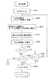
(6)LUT作成作業:
以下、上記各工程を一連の作業として実施してLUTを生成する作業をフローチャートに沿って説明する。図8は、LUT作成作業の全体を示すゼネラルフローである。同図において、ステップS100では上記コンピュータ10にて図4の右側に示すように、CMY色空間で各軸に沿って等間隔に離れた103個の格子点からなる立方格子を規定する。ステップS110ではコンピュータ10を介して印刷装置12を制御し、当該格子点の各色成分をカラー画像データとする色パッチを印刷させる。そして、ステップS120では上記測色器20を使用して印刷された色パッチPを測色し、103個のサンプルデータを生成する。
【0072】
ステップS130では、ターゲット座標Tを生成するため、図5に示すようにディスプレイ11で使用するsRGB色空間で各軸に沿って等間隔に離れた173個の格子点からなる立方格子を規定する。ステップS140では、公知の演算式に基づいて上記各立方格子点をLuv座標に変換する。さらに、ステップS150において当該変換後のLuv座標を印刷装置12の色域内にマッピングし、ステップS160において肌色やグレー等で好ましい発色となるように補正を行う。この補正後のLuv座標がターゲット座標Tである。
【0073】
ステップS200においては、上記103個のサンプルデータと173個のターゲット座標Tとを利用して試行を行い、所定のターゲット座標Tの色と同色とみなすことができるCMY座標を算出し、図示しないバッファに出力する。ステップS300では当該ステップS200の試行処理にて173個のターゲット座標Tに対するCMY座標を決定したか否かを判別し、全ターゲット座標Tに対してCMY座標を決定するまでステップS200以降の処理を繰り返す。ステップS300にて全ターゲット座標Tに対する処理が終了したと判別されたときには、ステップS310にて分版処理を行い、ステップS320にてsRGB座標とCcMmYK座標とを対応づけた最終的なLUTを生成する。
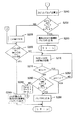
【0074】
図9,図10は、上記ステップS200の試行処理を示すフローチャートである。図においてステップS202では、CMY色空間中での初期座標の全色成分をαとして任意のターゲット座標Tに対して共通の初期座標を与える。ステップS205では、上記式(1)に示すスプライン補間演算によりCMY座標tiをLuv座標t’iに変換する。ここで、iは正の整数であり初期座標については「0」であるとともに、1試行過程について「1」ずつインクリメントされる。ステップS210では、変換されたLuv座標t’iとターゲット座標Tとのずれ量ΔEを上記式(2)に基づいて計算する。
【0075】
さらに、ステップS215においては、スプライン補間関数に基づいて上記式(5)に示す逆行列Aを計算し、ステップS210にて算出したずれ量ΔEと上記ステップS205にて算出した変換後の座標の各成分を使用して上記式(3)に示す変化量dMを算出する。ステップS220ではこの算出結果を使用して式(7)に基づいて次なる座標ti+1を算出する。本発明においては、予め所定の試行回数Nが与えられており、ステップS205〜S220の処理を繰り返すたびにカウンタnをインクリメントするようになっている。
【0076】
ステップS225では、このカウンタnが試行回数Nより小さいか否かを判定しており、カウンタnが試行回数Nより小さいと判別されたときにはステップS230にて上記ずれ量ΔEが所定のしきい値εより小さいか否かを判別する。ステップS230にてずれ量ΔEが所定のしきい値εより小さいと判別されないときには、上記ステップS205以降の処理を繰り返す。ステップS230にてずれ量ΔEが所定のしきい値εより小さいと判別されたときには、ステップS240にてこの時点のCMY座標tiとターゲット座標Tとを対応づけてバッファに出力する。
【0077】
上記ステップS225にてカウンタnが試行回数Nより小さいと判別されないときにはステップS235にて上記ずれ量ΔEが所定のしきい値εより小さいか否かを判別する。同ステップS235にて上記ずれ量ΔEが所定のしきい値εより小さいと判別されたときには上記ステップS240を実行する。ずれ量ΔEが所定のしきい値εより小さいと判別されないときには、初期座標C=M=Y=αにて試行を開始して所定回数Nでずれ量がしきい値εより小さくならなかった場合であるから、次に初期座標を変更するため、図10に示すステップS245以降を実行する。
【0078】
図10に示す処理では、しきい値εでの拘束条件を緩くしている。本発明においてはしきい値εを非常に厳しい条件としており、図9に示すフローチャートにおいてこのしきい値ε以下の色差となるCMY座標を決定できなかった場合、初期座標を変更して試行を繰り返してもずれ量ΔEが再びしきい値ε以下にならない場合もありえる。そこで、非常に多数回の試行を防止するため、しきい値εでの判別より少し条件を緩め、かつ、精度上問題とならないようなずれ量ΔEとなるように、Luvの各成分毎のずれ量をしきい値βにて判別している。ここで、β>εであるが、βは高精度のLUTを生成するために充分な値となっている。むろん、ここでしきい値βによる判別を行わず、しきい値εによる判別を続行することも可能である。
【0079】
このため、ステップS245では、ターゲット座標Tの色成分と変換後のLuv座標t’iの色成分とを使用してLuv座標での各成分毎のずれ量ΔL,Δu,Δvを算出する。ステップS250では、これらの各成分の総てがβより小さいか否かを判別しており、同ステップS250にて各成分の総てがβより小さいと判別されたときにはステップS260にて上記図9に示す試行工程において最終のCMY座標をバッファに出力する。すなわち、当該CMY座標は各成分のずれ量ΔL,Δu,Δvが総てしきい値β以下であることから、このCMY座標の色はターゲット座標Tの色に充分近い色であるとしている。
【0080】
ステップS250にて各成分のいずれか一つでもβより大きいと判別されたときには、ステップS255にて初期座標を全色成分が「0」である座標に変更する。ステップS265では、初期座標の全色成分が最大階調値である「255」を超えているか否かを判別している。これは、再試行段階で初期座標を変更したときに初期座標が最大階調値を超えないようにするためであり、ここで初期座標の全色成分が最大階調値である「255」を超えているときには、初期座標を変更してもずれ量がしきい値β以下に収束しなかった場合であり、この場合は試行過程でΔEが最小となったときのCMY座標をステップS290にてバッファに出力する。尚、本発明においてこの処理を行っているとしても本発明によって実際に生成されるLUTにおいては、後述するように非常にずれ量の小さいデータを形成することができる。
【0081】
ステップS265にて初期座標のいずれかの色成分が「255」を超えていないときには、ステップS270にて上記ステップS205〜S220と同様の処理を行う。すなわち、初期座標を変更した状態で上述の試行を行う。この試行の後、ステップS275では上記と同様にカウンタnが試行回数Nより小さいか否かを判別し、カウンタnが試行回数Nより小さいと判別されたときにはステップS282にて上記ずれ量ΔEが所定のしきい値εより小さいか否かを判別する。ステップS282にてずれ量ΔEが所定のしきい値εより小さいと判別されないときには、上記ステップS270にてステップS205〜S220と同様の処理を実行する。ステップS282にてずれ量ΔEが所定のしきい値εより小さいと判別されたときには、ステップS286にてこの時点のCMY座標tiとターゲット座標Tとを対応づけてバッファに出力する。
【0082】
上記ステップS275にてカウンタnが試行回数Nより小さいと判別されないときにはステップS280にてずれ量ΔL,Δu,Δvを算出し、これらの各成分の総てがβより小さいか否かを判別する。同ステップS280にて各成分の総てがβより小さいと判別されたときにはステップS286にて試行工程の最終段階でのCMY座標をバッファに出力する。ステップS280にて各成分のいずれかが一つでもβより大きいと判別されたときには、ステップS284にて初期座標CMYの全成分に一定値Δγを加えて上記ステップS265以降の処理を繰り返す。このように、初期座標を変更するに当たりしきい値εによる判別より緩い条件であるしきい値βによる判別を行うことによって、必要以上に精度を落とすことなく、より確実にCMY座標とターゲット座標Tとを対応づけることができる。
【0083】
図11は、作成されたLUTに規定された所定のCMY座標を使用して印刷装置12にて色パッチを印刷し当該色パッチを測色して得られたLuv座標と、LUTにおいて上記CMY座標に対応づけられたLuv座標との色差をプロットした図である。同図において縦軸は積算値であり、横軸は色差範囲である。例えば、横軸「0」については色差が「0〜0.5」の範囲にあるものの積算値を示しており、横軸「0.5」については色差が「0.5〜1」の範囲にあるものの積算値を示している。尚同図は173個の参照点のうち約1400点について積算したものであり、比較のため上記従来例に示す体積補間演算にて作成したLUTについて同条件で積算したものを左側に並べて示している。同図に示すように、色差範囲が「0〜2.5」という非常に小さな値となっているものは、体積補間によるものと比較して本発明の方が圧倒的に多く、色差範囲「2.5以上」という大きな値となっているものは本発明の方が圧倒的に少ない。従って、色差の平均値および分散は体積補間によるものと比較して本発明の方が小さくなり、このことからも本発明によれば全色域に渡って高精度の変換が可能であることが分かる。
【0084】
(7)作成された色変換テーブルデータに基づく色変換処理:
以上のようにして作成されたLUTは、汎用的なコンピュータにて汎用的に行われている印刷処理にて使用される。図12は、印刷時に当該LUTを使用するコンピュータ構成例を示すブロック図である。コンピュータ110は汎用的なパーソナルコンピュータであり、プリンタドライバ(PRTDRV)210と入力機器ドライバ(DRV)220とディスプレイドライバ(DRV)230とがOS200に組み込まれている。ディスプレイDRV230はディスプレイ180における画像データ等の表示を制御するドライバであり、入力機器DRV220はシリアル通信用I/O190aを介して入力される上記キーボード310やマウス320からのコード信号を受信して所定の入力操作を受け付けるドライバである。
【0085】
APL250は、カラー画像のレタッチ等を実行可能なアプリケーションプログラムであり、利用者は当該APL250の実行下において上記操作用入力機器を操作して当該カラー画像を印刷装置400にて印刷させることができる。このようなカラー画像の印刷時に本発明によって作成されたLUTが参照される。APL250にて作成されるカラー画像のカラー画像データ150aはRGBの各色成分を階調表現したドットマトリクス状のデータであり、sRGB規格に準拠したデータであるとともに、HDD150に保存される。
【0086】
上記PRTDRV210は印刷を実行するために、画像データ取得モジュール210aと色変換モジュール210bとハーフトーン処理モジュール210cと印刷データ生成モジュール210dとを備えている。また、本発明によって作成されたLUT150bはHDD150に保存されている。APL250実行時に利用者が印刷実行指示を行うと、印刷にかかる画像データ150aが画像データ取得モジュール210aに取得され、画像データ取得モジュール210aは上記色変換モジュール210bを起動する。色変換モジュール210bは、sRGB階調値をCcMmYK階調値に変換するモジュールであり、上記173個の参照点から643個の参照点を生成するとともに、これらの参照点を使用して任意のsRGBドットデータを体積補間によってCcMmYKドットデータに変換する。
【0087】
色変換モジュール210bが色変換を行ってCcMmYKの階調データを生成すると、当該CcMmYKの階調データは上記ハーフトーン処理モジュール210cに受け渡される。ハーフトーン処理モジュール210cは、各ドットのCcMmYK階調値を変換してインク滴の記録密度で表現するためのハーフトーン処理を行うモジュールであり、変換後の記録密度でインクを付着させるためのヘッド駆動データを生成する。印刷データ生成モジュール210dはかかるヘッド駆動データを受け取って、印刷装置400で使用される順番に並べ替えるラスタライズを行う。このラスタライズの後、画像の解像度などの所定の情報を付加して印刷データを生成し、パラレル通信用I/O190bを介して印刷装置400に出力する。印刷装置400においては当該印刷データに基づいて上記ディスプレイ180に表示された画像を印刷する。
【0088】
この印刷処理において、色変換は本発明によって作成されたLUTを参照して行われるので、ディスプレイ180および印刷装置400の色域全域に渡って高精度に色変換を行うことが可能であり、トーンジャンプの無い高画質の印刷を実施することができる。尚、以上の説明はPRTDRV210による非常に汎用的な印刷処理である。従って、本発明にかかる色変換テーブル作成方法にてLUTを作成すれば、従来の印刷処理にて使用されていたLUTを本発明によるLUTに置き換えるだけで多くの印刷装置にてハードウェア構成を全く変えることなく、非常に高画質の印刷を実行可能にすることができる。
【0089】
(8)他の実施形態:
以上説明した実施形態においては、試行工程にて試行回数Nで所望のずれ量以下にするために、しきい値εとしきい値βとを使用していたが、ずれ量をスムーズに小さくするためにはこのようなしきい値の変更以外にも種々の構成を採用可能である。すなわち、上記試行工程ではスプライン補間関数にてCMY座標をLuv座標に変換していたが、多次のスプライン曲線はその曲線がうねるようになることから、このうねりに起因してずれ量がスムーズに小さくならないことがある。
【0090】
このような場合にはCMY座標からLuv座標への変換手法を単純な手法に変更すればずれ量がスムーズに小さくなることが多い。例えば、スプライン補間関数ではなく、体積補間や三角錐補間を採用することが可能である。変換手法を変更した場合であっても、ずれ量がある程度小さくなってからスプライン補間関数を使用して変換を行えば、高精度にCMY座標とLuv座標とを対応づけることができる。変換手法を変更するタイミングとしても種々のタイミングを採用可能である。例えば、通常はスプライン補間によって変換を行いつつも所定の試行回数でずれ量がしきい値以下にならないときに変換手法を変更するよう構成しても良いし、試行工程の初期には上記体積補間や三角錐補間を行うこととし、ある程度ずれ量が小さくなってからスプライン補間を行うようにしても良い。
【0091】
以上説明したように、本発明においては第2色空間から第1色空間へ高精度に変換可能な状況において、第1色空間内にターゲット座標を決定し第2色空間内に任意の座標を決定する。そして、第2色空間内の座標を第1色空間内の座標へ変換するとともにそのずれ量を算出し、当該ずれ量が所定のしきい値以下になるように第2色空間内の座標を移動させる試行を繰り返す。従って、高精度の変換のみを使用して第1色空間と第2色空間との対応関係を規定することができる。このようにして規定された対応関係に基づいて色変換を行うと、表色空間の全域で高精度の色変換を可能である。
【図面の簡単な説明】
【図1】色変換テーブル作成方法の工程を概略的に説明する説明図である。
【図2】色変換テーブル作成方法の各工程の関係を示すブロック図である。
【図3】色変換テーブル作成装置の構成例を示すブロック図である。
【図4】サンプルデータを生成する様子を説明する説明図である。
【図5】ターゲット座標を決定する様子を説明する説明図である。
【図6】CMY座標の色をLuv座標の色に収束させる様子を説明する説明図である。
【図7】Luv色空間を模式的に示す図である。
【図8】LUT作成作業の全体を示すゼネラルフローである。
【図9】試行処理を示すフローチャートである。
【図10】試行処理を示すフローチャートである。
【図11】色差を各範囲毎に積算した積算値を示すグラフである。
【図12】LUTを使用するコンピュータ構成例を示すブロック図である。
【符号の説明】
10…コンピュータ
11…ディスプレイ
12…印刷装置
20…測色器
30…サンプルデータ
31…ターゲット座標決定部
32…変換対象座標決定部
33…変換部
34…ずれ量算出部
35…試行部
36…分版処理部
37…LUT生成部[0001]
BACKGROUND OF THE INVENTION
The present invention relates to a color conversion table creation method and a color conversion table creation apparatus. , Color conversion table creation program, color conversion device and printing device About.
[0002]
[Prior art]
An image device such as a display or a printer normally expresses an arbitrary color using color image data in which color components of three colors are expressed by gradation values. For example, an RGB color system using three colors of R (red), G (green), and B (blue) and a CMY color system using three colors of C (cyan), M (magenta), and Y (yellow) Various color systems are used. Since this color system is generally a device-independent color unique to an image device, an LUT (look-up table) that defines the correspondence between the color systems to enable the same image to be output in the same color between various image devices. ) Is used. The LUT defines the correspondence between the color system of the input side image device and the color system of the output side image device, and the correspondence between the color system of the output side image device and the absolute color space. There is something.
[0003]
The LUT in a printing device is usually M 3 Since it is necessary to define the correspondence with the coordinates (M is the number of grids of each component of the LUT), and it is unrealistic to measure all points with the colorimeter, N 3 M (M> N) coordinate points as sample data 3 Specifies the number of coordinate points. For example, when associating a Luv coordinate value with a CMY coordinate value, N printed based on a predetermined CMY value 3 Each patch is measured with a colorimeter to obtain a Luv coordinate value, and a linear interpolation operation such as volume interpolation is performed using the obtained correspondence, and an arbitrary M 3 CMY coordinate values for each Luv coordinate value were calculated.
[0004]
[Problems to be solved by the invention]
The conventional color conversion program described above has the following problems.
That is, since the sample color patch is printed by the printing apparatus, the CMY coordinate values can be selected from the coordinate values of the cubic grid points in the CMY color system, but the Luv color system corresponding to the color measurement result, etc. The lattice points formed by the coordinate values of the uniform perceptual color space are generally distorted. When converting arbitrary coordinates in cubic lattice points to arbitrary coordinates in distorted lattice points in the above volume interpolation calculation, it is possible to convert with high accuracy, but arbitrary coordinates in distorted lattice points can be converted into cubic lattices with high precision. In order to convert to arbitrary coordinates within a point, a very large number of grid points are required. 3 A single coordinate point is not sufficient. Therefore, it cannot be said that the accuracy of the LUT created as described above is high.
[0005]
In actual printing, an arbitrary coordinate value is calculated by performing an interpolation operation with the coordinate value defined in the LUT, so that color conversion cannot be performed with high accuracy during printing. Specifically, a phenomenon in which a certain region of the color space is locally less accurate than the surrounding region cannot be avoided, and a tone jump occurs in the print result. Also, with this technique, a certain level of high accuracy cannot be ensured for all types of printing apparatuses, and color conversion in certain models may protrude and become low accuracy.
The present invention has been made in view of the above problems, and enables high-accuracy color conversion in the entire color space and can generate a color conversion table that does not cause model dependence in conversion accuracy. Color conversion table creation method and color conversion table creation device , Color conversion table creation program, color conversion device and printing device The purpose is to provide.
[0006]
[Means for Solving the Problems]
In order to achieve the above object, the invention according to
[0007]
In the invention according to
[0008]
First, target coordinates for which correspondence is defined as a color conversion table in the target coordinate determination step are determined in the first color space, and coordinates to be converted in the second color space in the conversion target coordinate determination step Is determined. In the conversion step, the coordinates to be converted are converted into corresponding coordinates in the first color space based on the sample data. As described above, this conversion can be performed with high accuracy. In the trial process, the conversion target coordinate determination process and the conversion process are repeatedly tried so that the amount of deviation between the corresponding coordinates in the first color space converted in the conversion process and the target coordinates becomes small. In other words, the amount of shift in the first color space is usually gradually reduced by repeated trials. Then, in the color conversion table data generation step, the coordinates in the second color space that is the conversion target when the deviation amount is equal to or less than a predetermined threshold in the trial step are associated with the target coordinates. Generate color conversion table data.
[0009]
That is, in the present invention, the coordinates in the second color space are converted into the coordinates in the first color space, and the trial is repeated until the coordinates after the conversion approach the target coordinates and below a predetermined threshold value. Therefore, by making this threshold value sufficiently small, the coordinates in the second color space after the trial and the coordinates in the first color space can be regarded as the same color. The coordinates of the color space can be associated with high accuracy. In addition, the determination using the threshold value is not limited to the configuration in which the shift amount is directly compared with the predetermined threshold value, and the shift amount is a component along the axis constituting the first color space. It is also possible to adopt a configuration that determines whether or not the component is equal to or less than a predetermined threshold value. Here, the reason why the coordinates of the two color spaces are associated with high accuracy is that the coordinate conversion from the second color space to the first color space can be performed with high accuracy in the conversion step. That is, even if the difference between the coordinate after conversion and the target coordinate becomes a predetermined value or less, if the conversion accuracy is low, the coordinate in the second color space and the target coordinate cannot be regarded as the same color. This is because even if the converted coordinates and the target coordinates are very close in the first color space, it can be considered that they are close by chance due to an accuracy error.
[0010]
In defining the correspondence between the target coordinates and the second color space, by repeating the above trial, the color conversion can be performed without performing the conversion from the first color space to the second color space, which is a low-precision conversion. Table data can be generated, and there is no need to convert target coordinates with low-precision conversion once for any target coordinates. Furthermore, since the coordinates in the second color space gradually approach the target by trial, the corresponding coordinates in the second color space can be obtained without being affected by the position of the first color space or the arrangement of the sample data for any target coordinates. Can be requested. Therefore, M required for general LUT 3 Individual coordinates can be easily obtained. Furthermore, since the coordinates in the second color space are moved by trial, even if some data of the sample data is incorrect, the color conversion table data already generated in the above process is used as sample data. The color conversion table data in which the precise correspondence relationship is gradually increased increases, and finally, the color conversion table data in which the correspondence relationship is defined with high accuracy at all coordinates can be obtained.
[0011]
Here, regarding the accuracy by color conversion, conversion from the second color space to the first color space can be converted with higher accuracy than conversion from the first color space to the second color space based on sample data. I just need it. That is, if the conversion from the second color space to the first color space can be performed with high accuracy, the result of the trial process is higher than the direct conversion of the target coordinates into the coordinates of the second color space. Can be defined. The merit of implementing the present invention increases as the accuracy difference between the two conversions increases. This conversion method is not particularly limited, but assuming an interpolation calculation, a situation in which a difference in conversion accuracy occurs tends to occur as described above. That is, when a color expressed in the coordinates of the second color space is output by a predetermined image device and the output color is measured to obtain the coordinates in the first color space, these correspondences become sample data. However, it is usually easy to control which color is output by the image equipment.
[0012]
Therefore, if the color of the coordinates constituting the cubic lattice in the second color space is output, the corresponding color is not generally a cubic lattice in the first color space, but the coordinates in the cubic lattice are converted to non-cubic lattices by interpolation. It is very easy to convert the coordinates into the internal coordinates, that is, it can be performed with high accuracy, but the inverse conversion is not easy and generally has low accuracy. Therefore, when the present invention is applied in such a situation, the correspondence between the two spaces can be defined with high accuracy without performing low-precision conversion, so that color conversion table data capable of color conversion with very high accuracy can be generated. can do. In addition, when implementing a low-accuracy conversion method that converts the coordinates in the non-cubic lattice to the coordinates in the cubic lattice, local variations in the conversion accuracy are likely to occur due to the shape of the non-cubic lattice. However, in the present invention, since high-accuracy conversion is used in the present invention, there is no local variation in the color conversion accuracy by the color conversion table data after generation. There is no dependency.
[0013]
In the target coordinate determination step, it is only necessary to determine the coordinates of the color conversion table data generation target, and the target coordinates can be arbitrary coordinates. Needless to say, if the target coordinates are determined as will be described later, it can be configured so as to provide suitable effects in various respects. It is only necessary to be able to determine the conversion target coordinates in the conversion target coordinate determination step.In the present invention, because the coordinates are moved by trial, even if any coordinate is selected at the initial stage of the trial, the above deviation amount is usually set. Although it can be made lower than the desired threshold value, it is of course possible to adopt various ideas such as improving the possibility of convergence below the threshold value as will be described later. In the trial process, it is only necessary to reduce the amount of deviation between the corresponding coordinates in the first color space converted by a plurality of trials and the target coordinates, and various methods such as a Gauss-Newton method and a gradient search method can be used. Optimization techniques can be employed. In the color conversion table data generation step, it is only necessary to set a predetermined threshold value and acquire a correspondence relationship that is less than or equal to the threshold value. As a result, the color conversion table data is obtained by acquiring a large number of correspondence relationships. Can be generated.
[0014]
According to a second aspect of the present invention, the first color space and the second color space are based on the correspondence between the first color space and the second color space defined by a predetermined number of sample data acquired in advance. A color conversion table creation method for creating color conversion table data including a large number of data that defines a correspondence relationship between the first color and the sample data, wherein substantially cubic lattice points are configured in the second color space. In a situation where the corresponding lattice points in the space are non-cubic, a target coordinate determination step for determining the target coordinates of the target for which the correspondence is defined in the first color space, and conversion in the second color space The conversion target coordinate determining step for determining the target coordinates, the conversion step for converting the coordinates to be converted into corresponding coordinates in the first color space based on the sample data, and the conversion step. A trial step of repeatedly trying the conversion target coordinate determination step and the conversion step so that the amount of deviation between the corresponding coordinates in the first color space and the target coordinate is small, and the amount of deviation is predetermined in the trial step A color conversion table data generation step for generating color conversion table data by associating the coordinates in the second color space to be converted with the target coordinates when the threshold value is less than or equal to the threshold value It is as.
[0015]
That is, the method of defining the correspondence between the color of the coordinate in the second color space and the color of the target coordinate as a color conversion table data at the stage where the color of the target color is finally regarded as the same color in a trial process is various situations. Is applicable. In the present invention, the target coordinate determining step and the conversion target coordinates in a situation in which substantially cubic lattice points are configured in the second color space by the sample data and the corresponding lattice points in the first color space are non-cubic. A determination process, a conversion process, a trial process, and a color conversion table data generation process are applied. In this situation, it is generally easy and highly accurate to obtain the coordinates in the non-cubic lattice points based on the coordinates in the substantially cubic lattice points by interpolation or the like. Therefore, it is possible to generate color conversion table data capable of color conversion with high accuracy even in this situation. Here, the lattice points need only be substantially cubic lattices, that is, the coordinate points of the sample data are located at substantially the apexes of the cube, and are not strictly required to be a cube. Except for such a situation, various configurations, methods, devices, etc. can be adopted as in the first aspect.
[0016]
Furthermore, the invention according to
[0017]
As described above, the present invention is executed under various circumstances. As a preferred example, the invention according to
[0018]
Furthermore, in the invention according to
[0019]
The invention according to
[0020]
In obtaining the target coordinates from the coordinates in the third color space, the invention according to
[0021]
Furthermore, in the invention according to
[0022]
The color gamut is generally different between an image device that uses the second color space and an image device that uses the third color space. When the color gamuts are different, there is a color that can be output by one image device and cannot be output by the other image device. In this case, even if a color that cannot be output is defined by the color conversion table data, the color is not referred to when the color conversion table data is used. Therefore, if gamut mapping is performed, color conversion table data can be defined for colors that can be output in common to both image devices. Of course, in addition to the above gamut mapping, various adjustments are possible in the sense of adjusting the color, such as adjusting the coordinate position with skin color or gray to adjust the color so that many users are satisfied. Is possible.
[0023]
In the trial process, it is only necessary to make a trial so that the amount of deviation is small, but various devices can be employed to converge the amount of deviation below a predetermined threshold value. As an example, in the invention according to claim 9, the conversion target coordinate determination step is configured such that the initial coordinates to be converted in the first trial step are the same coordinates with respect to arbitrary target coordinates. That is, when moving the coordinates in the second color space so as to reduce the shift amount in the trial process, if the shift amount calculation result is a local minimum value, it is moved in any direction on the calculation formula. However, it may appear that the amount of deviation does not become small. Whether or not such a local minimum value is reached may be strongly influenced by the initial coordinates to be converted in the first trial process. That is, the amount of deviation is smoothly reduced at certain initial coordinates, but the amount of deviation may not be smoothly reduced at other initial coordinates.
[0024]
In addition, when the color of the target coordinate and the color of the initial coordinate in the second color space corresponding to each other are very different from each other, it takes time until the deviation amount becomes a predetermined threshold value or less. As described above, the initial coordinates selected in the second color space are inadequate. However, in the present invention, it is complicated and difficult to individually select ideal initial coordinates for all target coordinates. Therefore, it is preferable that the initial coordinates in the second color space be the same coordinates with respect to arbitrary target coordinates. As the initial coordinates, it is preferable that the corresponding points in the first color space are not extremely far when compared with arbitrary target coordinates, and are coordinates that are not likely to fall into a local minimum value. Such coordinates are preferred initial coordinates for most target coordinates.
[0025]
In the invention according to claim 10 as a configuration suitable as a specific example of the initial coordinates, the first color space extends substantially on the axis with respect to a predetermined axis, and the conversion target coordinate determination step is the first trial. The initial coordinates to be converted in the process are set as the coordinates near the predetermined axis. That is, when the first color space extends substantially in the axis direction with respect to the predetermined axis, the coordinates near the axis are not more than a certain distance from the arbitrary coordinates in the first color space, and the first Compared with the case where coordinates deviated toward the end of the color space are selected as initial coordinates, it is possible to prevent trial start with a color far from the color of any target coordinate. Here, it is only necessary that the distance from the arbitrary coordinates to the coordinates in the vicinity of the axis is not biased, and the coordinates on the axis may be selected as the coordinates in the vicinity of the axis, or the coordinates in the vicinity thereof may be used. In the present invention, since the coordinates are sequentially moved, the strictness is not required for these coordinate positions. In addition, examples of the color space that extends substantially toward the axis with respect to the predetermined axis include Luv space and Lab space that extend approximately toward the L axis.
[0026]
Further, in the invention according to
[0027]
In the sample data, if the coordinates in the first color space are non-cubic lattices, it is very difficult to convert the coordinates in the first color space to the coordinates in the second color space, contrary to the above conversion. It is difficult to determine the positional relationship between arbitrary coordinates in the first color space and sample data, it is difficult to determine which sample data should be used for interpolation, and color components in the adjacent sample data change independently. This is because it is virtually impossible to consider only one color as an independent variable. This situation is common in real imaging equipment. For example, in a printing apparatus that uses a CMY color space as the second color space, it is possible to easily output the color of cubic lattice point coordinates by changing the output color image data independently of CMY, but the output color is measured. As a result of the coloration, for example, a distorted grid is formed in the Luv space.
[0028]
The above-mentioned spline interpolation is a very high-accuracy conversion method that can be considered at present, and is very suitable for use in the conversion process of the present invention. Of course, the conversion method used in the conversion process is limited to spline interpolation. However, various conversions can be adopted, and when a more accurate conversion method is developed in the future, a color conversion table capable of color conversion with higher accuracy can be provided by adopting the conversion method. .
[0029]
In the trial process, it is preferable to consider the case where the amount of deviation does not decrease smoothly. In the invention according to claim 12 as a configuration example therefor, the trial process includes the deviation in the first color space. When the amount does not fall below a predetermined threshold, the trial is aborted a predetermined number of times, and the conversion method in the conversion step is changed to retry. That is, it is preferable to use the most accurate conversion method that can be considered at present in the conversion process, but there may be a problem in the work of reducing the shift amount due to the conversion method. If the conversion method is changed and another method is retried, the deviation amount often decreases smoothly.
[0030]
Of course, also in this case, if the conversion is finally performed by a high-accuracy conversion method, the generated color conversion table data can be made highly accurate. As a suitable example of the situation in which such a conversion method is changed, there is usually a case where spline interpolation that can be converted with high accuracy is performed. In other words, when high-order spline interpolation is performed, the phenomenon that the shift amount does not become small as described above due to the curve shape occurs. In this case, interpolation using the vertex of the cube as a reference point or This problem can be easily avoided by changing to triangular pyramid interpolation.
[0031]
Further, as another configuration example in consideration of the case where the deviation amount does not become small smoothly, in the invention according to claim 13, in the trial step, the deviation amount in the first color space does not become a predetermined threshold value or less. Sometimes, the trial is aborted at a predetermined number of times, and the initial coordinates to be converted are changed in the first trial process to retry. That is, depending on the position of the initial coordinates, the amount of deviation may not be reduced smoothly. In this case, the amount of deviation is often reduced smoothly by changing the initial coordinates and retrying.
[0032]
As a configuration example when changing the initial coordinates as described above, in the invention according to claim 14, the first color space extends to a substantially axis target with respect to a predetermined axis, and the trial step is performed after the trial is terminated. Coordinates separated by a predetermined distance along a predetermined axis are retried as new initial coordinates. In other words, when the first color space extends substantially to the axis target with respect to the predetermined axis, it is preferable to use the coordinates near the axis as the initial coordinates as described above. If the coordinates that are separated from each other by a predetermined distance along the axis are used as new initial coordinates when the amount of deviation is not reduced smoothly, it is possible to retry using the preferred coordinates near the axis as initial coordinates.
[0033]
Furthermore, the invention according to claim 15 is the uniform color space obtained as information in the uniform color space such as the Luv color space by measuring the color sample output by the printing apparatus by giving the predetermined CMY coordinates by the colorimeter. When a plurality of sample data defining a correspondence relationship between the CMY color space and the uniform color space is given by the coordinates and the CMY coordinates, the RGB color space used on the display based on the sample data and the CMY colors A color conversion table creation method for creating color conversion table data including a large number of data defining a correspondence relationship with a space, wherein a plurality of coordinates forming a substantially cubic lattice in the RGB color space are converted with a predetermined arithmetic expression. A target uniform color space coordinate determining step for determining the corresponding uniform color space coordinate, and an initial CMY coordinate for determining an initial CMY coordinate in the CMY color space. Obtained in the determination step, the initial CMY coordinate conversion step for converting the initial CMY coordinates into uniform color space coordinates by interpolation based on the correspondence defined in the sample data, and the initial CMY coordinate conversion step. A shift amount calculating step for calculating a shift amount between the uniform color space coordinates and the target uniform color space coordinates, determining the CMY coordinates so that the shift amount in the uniform color space is small, and performing the interpolation calculation on the determined CMY coordinates The trial step of repeating the conversion to the uniform color space coordinates again and calculating the deviation amount again, and the CMY coordinates and the target uniform color when the deviation amount becomes a predetermined threshold value or less in the trial step. Corresponding to the spatial coordinates, the RGB coordinates of the conversion source of the associated target coordinates and the CMY coordinates are correlated, and a predetermined image Color conversion table data for generating color conversion table data for converting image data expressed in the RGB color space used in the display to image data expressed in the CMY color space used in the printing apparatus for printing And a generation step. That is, the present invention can be applied when creating an LUT that associates the color space between the display and the printing apparatus.
[0034]
As described above, the method of generating the color conversion table data by repeating the attempt to convert the coordinates in the second color space and bring them closer to the target coordinates in the first color space is realized in an actual apparatus. It can be easily understood that the present invention can be applied as a substantial apparatus. That is, there is no difference in that it is effective as a substantial apparatus as in claims 16 to 19. Of course, it goes without saying that an apparatus corresponding to
[0035]
In the case of software that implements the color conversion table creation method as an embodiment of the idea of the invention, it naturally exists on a recording medium on which such software is recorded and must be used. Therefore, the present invention can be realized as a color conversion table creation program as in
[0036]
In addition, even when the communication method is used as a supply method, the present invention is not changed. Further, even when a part is software and a part is realized by hardware, the idea of the invention is not completely different, and a part is stored on a recording medium and is appropriately changed as necessary. It may be in the form of being read. In addition, all functions may not be realized by the program itself, but may be realized by an external program or the like. Even in such a case, it is only necessary that each function can be realized by a computer.
[0037]
【The invention's effect】
As described above, claims 1 to 3, claim 15, claim 16 to claim 28 According to the invention, color conversion table data that associates the coordinates of the first color space with the coordinates of the second color space with high accuracy is generated, and high-accuracy color conversion is enabled over the entire color space. A color conversion table creation method and a color conversion table creation apparatus capable of generating a color conversion table that does not cause model dependence in conversion accuracy , Color conversion table creation program, color conversion device and printing device Can be provided.
According to the fourth aspect of the present invention, a trial can be performed while using the color difference as a shift amount, and a direct correspondence between color image data used in the imaging device can be calculated.
[0038]
Furthermore, according to the
Furthermore, according to the sixth aspect of the present invention, it is possible to easily select target coordinates and to generate a color conversion table that associates the third color space with the second color space.
Further, according to the seventh aspect of the invention, it is possible to generate a color conversion table that covers substantially the entire area in the third color space and defines the color space correspondence relationship between the image device and the image device.
Furthermore, according to the
[0039]
Furthermore, according to the invention concerning Claim 9, it can be set as a preferable initial coordinate about most target coordinates.
Furthermore, according to the tenth aspect of the present invention, it is possible to prevent a trial start with a color far from the color of an arbitrary target coordinate.
Furthermore, according to the eleventh aspect, the coordinates of the second color space can be converted into the coordinates of the first color space with very high accuracy.
[0040]
Further, according to the twelfth aspect of the present invention, the amount of deviation can be reduced smoothly during the retry process.
Furthermore, according to the invention of claim 13, the amount of deviation can be reduced smoothly during the retry process.
Furthermore, according to the fourteenth aspect of the present invention, it is possible to continue to select preferable initial coordinates in the retry process.
[0041]
DETAILED DESCRIPTION OF THE INVENTION
Here, embodiments of the present invention will be described in the following order.
(1) Configuration of the present invention:
(2) Generation of sample data:
(3) Determination of target coordinates:
(4) Trial process:
(5) Change of initial coordinates:
(6) LUT creation work:
(7) Color conversion processing based on the created color conversion table data:
(8) Other embodiments:
[0042]
(1) Configuration of the present invention:
FIG. 1 is an explanatory diagram for schematically explaining the steps of the color conversion table creation method according to the present invention, and FIG. 2 is a block diagram showing the relationship between the steps. In FIG. 1, the
[0043]
In the
[0044]
That is, the conversion target coordinate
[0045]
The CMY coordinates of the generated LUT can be uniquely associated with the coordinates of the CcMmYK color space, and the color
[0046]
The LUT generated in this way prescribes the color correspondence with high accuracy over the entire color gamut of the
[0047]
The color conversion table creation method according to the present invention associates the first color space with the second color space by performing many operations and repeating the calculation. Therefore, it is preferable to implement the method using a computer. In this case, the computer constitutes a color conversion table creating apparatus, and the executed program is the color conversion table creating program. FIG. 3 is a block diagram illustrating a configuration example of the color conversion table creation apparatus. In the figure, the
[0048]
The
[0049]
The conversion
[0050]
The color
[0051]
(2) Generation of sample data:
Hereafter, each process of the said color conversion table preparation method is demonstrated in detail. FIG. 4 is an explanatory diagram for explaining how the
[0052]
On the other hand, the
[0053]
That is, when calculating the spline interpolation function, the spline interpolation function is calculated in consideration of a function that can be changed independently for each of the CMY axes. When the sample data is a cubic lattice, the spline interpolation function is parallel to each axis. Since the movement of a point is equivalent to fixing only two components of coordinates and moving only one component, a spline interpolation function can be calculated easily and accurately. However, in the opposite case, it is practically impossible to know the change of the CMY component when only one component of Luv is changed. Therefore, as shown in FIG. 4, the function g (C, M, Y) for calculating the Luv coordinates based on the CMY coordinates can be accurately obtained, but the function f (for calculating the CMY coordinates based on the Luv coordinates is used. It is virtually impossible to accurately determine L, u, v). The present invention is implemented in such a situation that the color corresponding to the vertex of the cubic lattice can be easily printed in the CMY color space, and as a result, the CMY color space can be accurately converted to the Luv color space.
[0054]
(3) Determination of target coordinates:
FIG. 5 is an explanatory diagram for explaining how the target coordinates are determined by the target coordinate
[0055]
The conversion from the sRGB coordinates to the Luv coordinates can be easily executed by a known arithmetic expression. 3 The lattice points are converted into a coordinate group Gr in the Luv color space by calculation. By this conversion, colors sparsely distributed over the entire color gamut of the
[0056]
Therefore, in order to match the both, colors outside the color gamut of the
[0057]
(4) Trial process:
FIG. 6 is an explanatory diagram for explaining a state in which the
[0058]
FIG. 7 is a diagram schematically showing the Luv color space, and the achromatic color is a color on the L axis in the Luv color space. Therefore, the initial coordinate t 0 (C 0 , M 0 , Y 0 ) Converted coordinates t ′ 0 Is located near the L axis. Since the Luv color space has a substantially symmetric shape with respect to the L-axis as shown in the figure, the color on the L-axis is extremely distant from the coordinates located at the end of the Luv color space. The coordinates t ' 0 Is a coordinate suitable as an initial coordinate common to all target coordinates T sparsely spread in the Luv color space. Common initial coordinate t for all target coordinates T 0 , It is not necessary to change the initial coordinates in the CMY color space in consideration of the position of the individual target coordinates T, and the trial can be started easily. Of course, the initial coordinate t for all target coordinates T 0 When the trial is started, the color does not necessarily converge, and when the amount of deviation does not decrease smoothly in the trial process, that is, when the amount of deviation does not fall below the threshold value after a predetermined number of trials, the initial coordinates are set as described later. Change the to resume the attempt.
[0059]
When the conversion
[Expression 1]
[0060]
The
[Expression 2]
In the present invention, the conversion symmetric coordinate and the target coordinate T are regarded as the same color when the deviation amount ΔE is smaller than a predetermined minute threshold value ε, and the
[0062]
First, in the following equation (3), partial differentiation of each component ΔL, Δu, Δv in the above equation (2) is obtained. DM calculated by the equation (3) indicates a minute change in the direction of decreasing the deviation amount ΔE.
[Equation 3]
On the other hand, the change in the Luv color space when each component of arbitrary CMY coordinates is slightly changed is given by the Jacobian matrix J as shown in the following equation (4).
[Expression 4]
[0064]
Further, a change in the CMY color space when each component of an arbitrary Luv coordinate is slightly changed is given by the following equation (5) using the inverse matrix A of the Jacobian matrix J.
[Equation 5]
Since the right side of this equation (5) shows the change in the CMY space, the coordinate t in the next trial is 1 (C 1 , M 1 , Y 1 ) And initial coordinates t 0 (C 0 , M 0 , Y 0 ) Is equal to the change in the CMY space, Equation (6) is derived.
[Formula 6]
Substituting the above equation (5) into the right side of this equation (6) and further substituting the above equation (3), the following equation (7) is derived.
[Expression 7]
[0067]
The
[0068]
17 by trial of
[0069]
(5) Change of initial coordinates:
In the present invention, when the deviation amount does not fall below the threshold value after a predetermined number of trials, the initial coordinate is changed and the retry is made. As described above, since the initial coordinates are preferably set to the color near the L axis in the Luv space, the changed initial coordinates are also set to the color near the L axis. That is, the common initial coordinate t in FIG. 0 Corresponding coordinates t ′ in the Luv color space 0 If the shift amount does not decrease smoothly, the coordinates where all the color components are “0” in the CMY color space are set as initial coordinates. If the amount of deviation does not decrease smoothly even with the initial coordinates, the initial coordinates are further changed by incrementing all the color components by the same amount Δγ.
[0070]
FIG. 7 shows how the initial coordinates are changed. The coordinates corresponding to the coordinates where all color components are “0” in the CMY color space are t ′. 01 And sequentially t ′ along the L axis by further changing the initial coordinates. 02 , T ' 03 If the initial coordinates are changed in this way, the amount of deviation is smoothly reduced at any of the initial coordinates in the above trial process, and finally the same color as the color of the target coordinates T can be considered. Possible CMY coordinates can be determined. Of course, it is not certain whether coordinates with the same color components in the CMY color space are strictly achromatic, but in the present invention, the coordinates are moved so as to approach the target coordinates T in the trial process, There is no need for the corresponding coordinates to be exactly on the L axis.
[0071]
(6) LUT creation work:
Hereinafter, an operation of generating the LUT by performing the above steps as a series of operations will be described with reference to a flowchart. FIG. 8 is a general flow showing the entire LUT creation work. In the figure, in step S100, as shown on the right side of FIG. 4 by the
[0072]
In step S130, in order to generate the target coordinate T, as shown in FIG. 5, 17 separated at equal intervals along each axis in the sRGB color space used in the
[0073]
In step S200, the above 10 3 17 pieces of sample data 3 Trial is performed using the target coordinates T, CMY coordinates that can be regarded as the same color as the color of the predetermined target coordinates T are calculated, and output to a buffer (not shown). In step S300, the trial process in step S200 performs 17 3 It is determined whether or not CMY coordinates for each target coordinate T have been determined, and the processes in and after step S200 are repeated until CMY coordinates are determined for all target coordinates T. If it is determined in step S300 that the processing for all target coordinates T has been completed, color separation processing is performed in step S310, and a final LUT that associates sRGB coordinates with CcMmYK coordinates is generated in step S320. .
[0074]
9 and 10 are flowcharts showing the trial process in step S200. In the figure, in step S202, common initial coordinates are given to an arbitrary target coordinate T, where α is all the color components of the initial coordinates in the CMY color space. In step S205, the CMY coordinates t are calculated by the spline interpolation calculation shown in the above equation (1). i Luv coordinate t ' i Convert to Here, i is a positive integer, “0” for the initial coordinates, and incremented by “1” for one trial process. In step S210, the converted Luv coordinate t ′ i And the target coordinate T are calculated based on the above equation (2).
[0075]
Further, in step S215, the inverse matrix A shown in the above equation (5) is calculated based on the spline interpolation function, and each of the deviation amount ΔE calculated in step S210 and the converted coordinates calculated in step S205 is calculated. The amount of change dM shown in the above equation (3) is calculated using the components. In step S220, using this calculation result, the next coordinate t based on equation (7). i + 1 Is calculated. In the present invention, a predetermined number of trials N is given in advance, and the counter n is incremented each time the processes of steps S205 to S220 are repeated.
[0076]
In step S225, it is determined whether or not the counter n is smaller than the number of trials N. If it is determined that the counter n is smaller than the number of trials N, the deviation amount ΔE is determined to be a predetermined threshold value ε in step S230. It is determined whether or not it is smaller. If it is not determined in step S230 that the deviation amount ΔE is smaller than the predetermined threshold value ε, the processes in and after step S205 are repeated. When it is determined in step S230 that the deviation amount ΔE is smaller than the predetermined threshold value ε, the CMY coordinates t at this time are determined in step S240. i And the target coordinates T are output in correspondence to the buffer.
[0077]
If it is not determined in step S225 that the counter n is smaller than the number of trials N, it is determined in step S235 whether or not the deviation amount ΔE is smaller than a predetermined threshold value ε. If it is determined in step S235 that the shift amount ΔE is smaller than the predetermined threshold value ε, step S240 is executed. When it is not determined that the deviation amount ΔE is smaller than the predetermined threshold value ε, the trial is started at the initial coordinates C = M = Y = α, and the deviation amount is not smaller than the threshold value ε after a predetermined number N. Therefore, in order to change the initial coordinates, step S245 and subsequent steps shown in FIG. 10 are executed.
[0078]
In the process shown in FIG. 10, the constraint condition at the threshold ε is relaxed. In the present invention, the threshold value ε is a very strict condition, and when the CMY coordinates having a color difference equal to or smaller than the threshold value ε cannot be determined in the flowchart shown in FIG. 9, the initial coordinate is changed and the trial is repeated. However, the deviation amount ΔE may not be less than the threshold value ε again. Therefore, in order to prevent a very large number of trials, the deviation for each component of the Luv is set so that the deviation is a little relaxed than the determination with the threshold value ε and the deviation amount ΔE is not problematic in terms of accuracy. The amount is determined by the threshold value β. Here, β> ε, but β is a value sufficient to generate a high-precision LUT. Of course, it is also possible to continue the determination based on the threshold value ε without performing the determination based on the threshold value β.
[0079]
For this reason, in step S245, the color component of the target coordinate T and the converted Luv coordinate t ′. i Are used to calculate the shift amounts ΔL, Δu, Δv for each component in the Luv coordinates. In step S250, it is determined whether or not all of these components are smaller than β. If it is determined in step S250 that all of the components are smaller than β, the above-described FIG. The final CMY coordinates are output to the buffer in the trial process shown in FIG. That is, since the CMY coordinates are such that the deviation amounts ΔL, Δu, Δv of the components are all equal to or less than the threshold value β, the color of the CMY coordinates is sufficiently close to the color of the target coordinates T.
[0080]
If it is determined in step S250 that any one of the components is larger than β, the initial coordinates are changed to coordinates where all the color components are “0” in step S255. In step S265, it is determined whether or not all color components of the initial coordinates exceed the maximum gradation value “255”. This is to prevent the initial coordinates from exceeding the maximum gradation value when the initial coordinates are changed in the retry stage. Here, all color components of the initial coordinates are set to “255” which is the maximum gradation value. If it exceeds, the deviation amount does not converge below the threshold value β even if the initial coordinate is changed. In this case, the CMY coordinates when ΔE is minimized in the trial process are determined in step S290. Output to buffer. Even if this processing is performed in the present invention, in the LUT actually generated by the present invention, data with a very small deviation amount can be formed as will be described later.
[0081]
If any color component of the initial coordinates does not exceed “255” in step S265, the same processing as in steps S205 to S220 is performed in step S270. That is, the above-described trial is performed with the initial coordinates changed. After this trial, in step S275, it is determined whether or not the counter n is smaller than the number of trials N in the same way as described above. It is determined whether or not it is smaller than the threshold value ε. If it is not determined in step S282 that the deviation amount ΔE is smaller than the predetermined threshold value ε, the same processing as steps S205 to S220 is performed in step S270. When it is determined in step S282 that the deviation amount ΔE is smaller than the predetermined threshold value ε, the CMY coordinates t at this time are determined in step S286. i And the target coordinates T are output in correspondence to the buffer.
[0082]
If it is not determined in step S275 that the counter n is smaller than the number of trials N, the deviation amounts ΔL, Δu, Δv are calculated in step S280, and it is determined whether all of these components are smaller than β. If it is determined in step S280 that all of the components are smaller than β, the CMY coordinates at the final stage of the trial process are output to the buffer in step S286. If it is determined in step S280 that any one of the components is larger than β, a constant value Δγ is added to all components of the initial coordinates CMY in step S284, and the processing from step S265 is repeated. As described above, when the initial coordinate is changed, the determination based on the threshold value β, which is a milder condition than the determination based on the threshold value ε, is performed, so that the CMY coordinates and the target coordinates T are more reliably detected without degrading the accuracy more than necessary. Can be associated with each other.
[0083]
FIG. 11 shows a Luv coordinate obtained by printing a color patch with the
[0084]
(7) Color conversion processing based on the created color conversion table data:
The LUT created as described above is used in a printing process that is performed on a general-purpose computer. FIG. 12 is a block diagram illustrating a computer configuration example that uses the LUT during printing. The
[0085]
The
[0086]
The
[0087]
When the
[0088]
In this printing process, the color conversion is performed with reference to the LUT created according to the present invention. Therefore, the color conversion can be performed with high accuracy over the entire color gamut of the
[0089]
(8) Other embodiments:
In the embodiment described above, the threshold value ε and the threshold value β are used in order to make the number of trials N or less the desired deviation amount in the trial process, but in order to reduce the deviation amount smoothly. In addition to such a change in threshold value, various configurations can be employed. That is, in the above trial process, the CMY coordinates are converted to the Luv coordinates by the spline interpolation function. However, since the multi-order spline curve becomes wavy, the deviation amount is smooth due to this waviness. May not get smaller.
[0090]
In such a case, if the conversion method from the CMY coordinates to the Luv coordinates is changed to a simple method, the amount of deviation often decreases smoothly. For example, instead of the spline interpolation function, volume interpolation or triangular pyramid interpolation can be employed. Even when the conversion method is changed, CMY coordinates and Luv coordinates can be associated with high accuracy by performing conversion using a spline interpolation function after the amount of deviation becomes small to some extent. Various timings can be adopted as the timing for changing the conversion method. For example, the conversion method may be changed when the amount of deviation does not fall below the threshold value after a predetermined number of trials while the conversion is usually performed by spline interpolation. Alternatively, the triangular pyramid interpolation may be performed, and the spline interpolation may be performed after the deviation amount is reduced to some extent.
[0091]
As described above, in the present invention, in a situation where conversion from the second color space to the first color space can be performed with high accuracy, target coordinates are determined in the first color space, and arbitrary coordinates are set in the second color space. decide. Then, the coordinates in the second color space are converted into the coordinates in the first color space and the deviation amount is calculated, and the coordinates in the second color space are set so that the deviation amount is equal to or less than a predetermined threshold value. Repeat the move attempt. Therefore, the correspondence between the first color space and the second color space can be defined using only high-precision conversion. If color conversion is performed based on the correspondence defined in this way, color conversion can be performed with high accuracy in the entire color space.
[Brief description of the drawings]
FIG. 1 is an explanatory diagram schematically illustrating steps of a color conversion table creation method.
FIG. 2 is a block diagram illustrating a relationship between steps of a color conversion table creation method.
FIG. 3 is a block diagram illustrating a configuration example of a color conversion table creation device.
FIG. 4 is an explanatory diagram for explaining how sample data is generated;
FIG. 5 is an explanatory diagram for explaining how to determine target coordinates;
FIG. 6 is an explanatory diagram for explaining how the colors of CMY coordinates converge to the colors of Luv coordinates.
FIG. 7 is a diagram schematically showing a Luv color space.
FIG. 8 is a general flow showing the entire LUT creation work.
FIG. 9 is a flowchart showing trial processing.
FIG. 10 is a flowchart showing trial processing.
FIG. 11 is a graph showing an integrated value obtained by integrating color differences for each range.
FIG. 12 is a block diagram illustrating a computer configuration example using an LUT.
[Explanation of symbols]
10 ... Computer
11 ... Display
12 ... Printing device
20 ... Colorimeter
30 ... Sample data
31 ... Target coordinate determination unit
32 ... Conversion target coordinate determination unit
33 ... Conversion unit
34: Deviation amount calculation unit
35 ... Trial part
36. Separation processing unit
37 ... LUT generator
Claims (28)
第1色空間内の任意座標と第2色空間内の任意座標とを相互に変換するに当たり、上記サンプルデータに基づく変換によって上記第1色空間から第2色空間への変換より上記第2色空間から第1色空間への変換の方が高精度に変換可能な状況において、
上記対応関係が規定される対象のターゲット座標を上記第1色空間内で決定するターゲット座標決定工程と、
上記第2色空間内で変換対象となる座標を決定する変換対象座標決定工程と、
上記サンプルデータに基づいて上記変換対象となる座標を第1色空間内の対応座標に変換する変換工程と、
同変換工程にて変換された第1色空間内の対応座標と上記ターゲット座標とのずれ量が小さくなるように上記変換対象座標決定工程と変換工程とを繰り返し試行する試行工程と、
当該試行工程において上記ずれ量が所定のしきい値以下になったときに上記変換対象となった第2色空間内の座標と上記ターゲット座標とを対応づけて色変換テーブルデータを生成する色変換テーブルデータ生成工程とを具備することを特徴とする色変換テーブル作成方法。A large number of data defining the correspondence between the first color space and the second color space based on the correspondence between the first color space and the second color space defined by a predetermined number of sample data acquired in advance. A color conversion table creation method for creating color conversion table data including:
When the arbitrary coordinates in the first color space and the arbitrary coordinates in the second color space are mutually converted, the second color is converted from the first color space to the second color space by conversion based on the sample data. In the situation where the conversion from space to the first color space can be converted with higher accuracy,
A target coordinate determination step of determining the target coordinates of the target for which the correspondence is defined in the first color space;
A conversion target coordinate determination step for determining coordinates to be converted in the second color space;
A conversion step of converting the coordinates to be converted into corresponding coordinates in the first color space based on the sample data;
A trial step of repeatedly trying the conversion target coordinate determination step and the conversion step so as to reduce the amount of deviation between the corresponding coordinates in the first color space converted in the conversion step and the target coordinates;
Color conversion for generating color conversion table data by associating the coordinates in the second color space to be converted with the target coordinates when the deviation amount becomes equal to or less than a predetermined threshold in the trial process A color conversion table creation method comprising: a table data generation step.
上記サンプルデータによって上記第2色空間内に略立方格子点が構成され、上記第1色空間内で対応する格子点が非立方体となる状況において、
上記対応関係が規定される対象のターゲット座標を上記第1色空間内で決定するターゲット座標決定工程と、
上記第2色空間内で変換対象となる座標を決定する変換対象座標決定工程と、
上記サンプルデータに基づいて上記変換対象となる座標を第1色空間内の対応座標に変換する変換工程と、
同変換工程にて変換された第1色空間内の対応座標と上記ターゲット座標とのずれ量が小さくなるように上記変換対象座標決定工程と変換工程とを繰り返し試行する試行工程と、
当該試行工程において上記ずれ量が所定のしきい値以下になったときに上記変換対象となった第2色空間内の座標と上記ターゲット座標とを対応づけて色変換テーブルデータを生成する色変換テーブルデータ生成工程とを具備することを特徴とする色変換テーブル作成方法。A large number of data defining the correspondence between the first color space and the second color space based on the correspondence between the first color space and the second color space defined by a predetermined number of sample data acquired in advance. A color conversion table creation method for creating color conversion table data including:
In the situation where a substantially cubic lattice point is configured in the second color space by the sample data, and the corresponding lattice point in the first color space is non-cubic.
A target coordinate determination step of determining the target coordinates of the target for which the correspondence is defined in the first color space;
A conversion target coordinate determination step for determining coordinates to be converted in the second color space;
A conversion step of converting the coordinates to be converted into corresponding coordinates in the first color space based on the sample data;
A trial step of repeatedly trying the conversion target coordinate determination step and the conversion step so as to reduce the amount of deviation between the corresponding coordinates in the first color space converted in the conversion step and the target coordinates;
Color conversion for generating color conversion table data by associating the coordinates in the second color space to be converted with the target coordinates when the deviation amount becomes equal to or less than a predetermined threshold in the trial process A color conversion table creation method comprising: a table data generation step.
上記予め規定された対応関係に基づいて上記第2色空間内の座標を第1色空間内の座標へ変換する変換工程を実行可能であり、
当該変換工程によって上記第2色空間における所定の座標に対する第1色空間の座標を求めるとともに、同座標と上記第1色空間内の所望の座標とのずれをフィードバックして上記第2色空間における次なる座標を決定する工程を繰り返し、上記第1色空間内の所望の座標に対応する上記第2色空間内の座標を求めて上記色変換テーブルデータにすることを特徴とする色変換テーブル作成方法。Correspondence between desired coordinates in the first color space and coordinates in the second color space based on the correspondence between the first color space and the second color space defined by a predetermined number of sample data acquired in advance A color conversion table creation method for creating color conversion table data including a large number of data defining
A conversion step of converting the coordinates in the second color space into the coordinates in the first color space based on the predefined correspondence relationship can be performed;
The conversion step obtains the coordinates of the first color space with respect to the predetermined coordinates in the second color space, and feeds back the deviation between the coordinates and the desired coordinates in the first color space to feed back the coordinates in the second color space. Creating a color conversion table characterized by repeating the step of determining the next coordinates to obtain the coordinates in the second color space corresponding to the desired coordinates in the first color space to obtain the color conversion table data Method.
上記RGB色空間で略立方格子を形成する複数の座標を所定の演算式で変換して対応する均等色空間座標を決定するターゲット均等色空間座標決定工程と、
上記CMY色空間で初期CMY座標を決定する初期CMY座標決定工程と、
上記サンプルデータにて規定された対応関係に基づいて補間演算によって上記初期CMY座標を均等色空間座標に変換する初期CMY座標変換工程と、
同初期CMY座標変換工程にて得られた均等色空間座標と上記ターゲット均等色空間座標とのずれ量を算出するずれ量算出工程と、
均等色空間におけるずれ量が小さくなるように上記CMY座標を決定し、決定したCMY座標を上記補間演算によって再度均等色空間座標に変換するとともに再度ずれ量の算出を行う試行を繰り返す試行工程と、
当該試行工程において上記ずれ量が所定のしきい値以下になったときのCMY座標と上記ターゲット均等色空間座標とを対応づけ、当該対応づけられたターゲット座標の変換元のRGB座標と上記CMY座標とを対応づけ、所定の画像を印刷するに当たり上記ディスプレイで使用されるRGB色空間で表現された画像データを印刷装置で使用されるCMY色空間で表現された画像データに変換するための色変換テーブルデータを生成する色変換テーブルデータ生成工程とを具備することを特徴とする色変換テーブル作成方法。The CMY color space is defined by the uniform color space coordinates obtained as information in the uniform color space such as the Luv color space obtained by measuring the color samples output by the printing apparatus by giving predetermined CMY coordinates and the CMY coordinates. When a plurality of sample data defining the correspondence relationship between the color space and the uniform color space are given, a large number of the correspondence relationships between the RGB color space used in the display and the CMY color space are defined based on the sample data. A color conversion table creation method for creating color conversion table data including data,
A target uniform color space coordinate determination step of converting a plurality of coordinates forming a substantially cubic lattice in the RGB color space with a predetermined arithmetic expression to determine a corresponding uniform color space coordinate;
An initial CMY coordinate determination step for determining initial CMY coordinates in the CMY color space;
An initial CMY coordinate conversion step of converting the initial CMY coordinates into uniform color space coordinates by interpolation based on the correspondence defined in the sample data;
A deviation amount calculating step of calculating a deviation amount between the uniform color space coordinates obtained in the initial CMY coordinate conversion step and the target uniform color space coordinates;
A trial step in which the CMY coordinates are determined so that the amount of deviation in the uniform color space is reduced, the determined CMY coordinates are converted into uniform color space coordinates again by the interpolation operation, and a trial for calculating the amount of deviation again is repeated;
Corresponding CMY coordinates when the deviation amount is equal to or smaller than a predetermined threshold value in the trial process and the target uniform color space coordinates, and converting the RGB coordinates of the corresponding target coordinates and the CMY coordinates To convert image data expressed in the RGB color space used in the above display to image data expressed in the CMY color space used in the printing apparatus when printing a predetermined image. A color conversion table creation method comprising: a color conversion table data generation step for generating table data.
第1色空間内の任意座標と第2色空間内の任意座標とを相互に変換するに当たり、上記サンプルデータに基づく変換によって上記第1色空間から第2色空間への変換より上記第2色空間から第1色空間への変換の方が高精度に変換可能な状況において、
上記対応関係が規定される対象のターゲット座標を上記第1色空間内で決定するターゲット座標決定手段と、
上記第2色空間内で変換対象となる座標を決定する変換対象座標決定手段と、
上記サンプルデータに基づいて上記変換対象となる座標を第1色空間内の対応座標に変換する変換手段と、
同変換手段にて変換された第1色空間内の対応座標と上記ターゲット座標とのずれ量が小さくなるように上記変換対象座標決定手段と変換手段とを繰り返し試行する試行手段と、
当該試行手段において上記ずれ量が所定のしきい値以下になったときに上記変換対象となった第2色空間内の座標と上記ターゲット座標とを対応づけて色変換テーブルデータを生成する色変換テーブルデータ生成手段とを具備することを特徴とする色変換テーブル作成装置。A large number of data defining the correspondence between the first color space and the second color space based on the correspondence between the first color space and the second color space defined by a predetermined number of sample data acquired in advance. A color conversion table creation device for creating color conversion table data including:
When the arbitrary coordinates in the first color space and the arbitrary coordinates in the second color space are mutually converted, the second color is converted from the first color space to the second color space by conversion based on the sample data. In the situation where the conversion from space to the first color space can be converted with higher accuracy,
Target coordinate determining means for determining the target coordinates of the object for which the correspondence is defined in the first color space;
Conversion target coordinate determining means for determining coordinates to be converted in the second color space;
Conversion means for converting coordinates to be converted into corresponding coordinates in the first color space based on the sample data;
Trial means for repeatedly trying the conversion target coordinate determination means and the conversion means so as to reduce the amount of deviation between the corresponding coordinates in the first color space converted by the conversion means and the target coordinates;
Color conversion for generating color conversion table data by associating the coordinates in the second color space to be converted with the target coordinates when the deviation amount becomes equal to or less than a predetermined threshold in the trial means. A color conversion table creation device comprising table data generation means.
上記サンプルデータによって上記第2色空間内に略立方格子点が構成され、上記第1色空間内で対応する格子点が非立方体となる状況において、
上記対応関係が規定される対象のターゲット座標を上記第1色空間内で決定するターゲット座標決定手段と、
上記第2色空間内で変換対象となる座標を決定する変換対象座標決定手段と、
上記サンプルデータに基づいて上記変換対象となる座標を第1色空間内の対応座標に変換する変換手段と、
同変換手段にて変換された第1色空間内の対応座標と上記ターゲット座標とのずれ量が小さくなるように上記変換対象座標決定手段と変換手段とを繰り返し試行する試行手段と、
当該試行手段において上記ずれ量が所定のしきい値以下になったときに上記変換対象となった第2色空間内の座標と上記ターゲット座標とを対応づけて色変換テーブルデータを生成する色変換テーブルデータ生成手段とを具備することを特徴とする色変換テーブル作成装置。A large number of data defining the correspondence between the first color space and the second color space based on the correspondence between the first color space and the second color space defined by a predetermined number of sample data acquired in advance. A color conversion table creation device for creating color conversion table data including:
In the situation where a substantially cubic lattice point is configured in the second color space by the sample data, and the corresponding lattice point in the first color space is non-cubic.
Target coordinate determining means for determining the target coordinates of the object for which the correspondence is defined in the first color space;
Conversion target coordinate determining means for determining coordinates to be converted in the second color space;
Conversion means for converting coordinates to be converted into corresponding coordinates in the first color space based on the sample data;
Trial means for repeatedly trying the conversion target coordinate determination means and the conversion means so as to reduce the amount of deviation between the corresponding coordinates in the first color space converted by the conversion means and the target coordinates;
Color conversion for generating color conversion table data by associating the coordinates in the second color space to be converted with the target coordinates when the deviation amount becomes equal to or less than a predetermined threshold in the trial means. A color conversion table creation device comprising table data generation means.
上記予め規定された対応関係に基づいて上記第2色空間内の座標を第1色空間内の座標へ変換可能であり、
当該変換によって上記第2色空間における所定の座標に対する第1色空間の座標を求める第1色空間座標算出手段と、
同算出された座標と上記第1色空間内の所望の座標とのずれをフィードバックして上記第2色空間における次なる座標の決定を繰り返す試行手段と、
上記第1色空間内の所望の座標に対応する上記第2色空間内の座標を求めて上記色変換テーブルデータにする色変換テーブルデータ生成手段とを具備することを特徴とする色変換テーブル作成装置。Correspondence between desired coordinates in the first color space and coordinates in the second color space based on the correspondence between the first color space and the second color space defined by a predetermined number of sample data acquired in advance A color conversion table creation device for creating color conversion table data including a large number of data defining
The coordinates in the second color space can be converted into the coordinates in the first color space based on the predefined correspondence;
First color space coordinate calculating means for obtaining coordinates of the first color space with respect to predetermined coordinates in the second color space by the conversion;
A trial unit that feeds back a deviation between the calculated coordinates and a desired coordinate in the first color space and repeats determination of the next coordinate in the second color space;
Color conversion table creation comprising color conversion table data generation means for obtaining coordinates in the second color space corresponding to desired coordinates in the first color space and converting the coordinates into the color conversion table data apparatus.
上記RGB色空間で略立方格子を形成する複数の座標を所定の演算式で変換して対応する均等色空間座標を決定するターゲット均等色空間座標決定手段と、
上記CMY色空間で初期CMY座標を決定する初期CMY座標決定手段と、
上記サンプルデータにて規定された対応関係に基づいて補間演算によって上記初期CMY座標を均等色空間座標に変換する初期CMY座標変換手段と、
同初期CMY座標変換手段にて得られた均等色空間座標と上記ターゲット均等色空間座標とのずれ量を算出するずれ量算出手段と、
均等色空間におけるずれ量が小さくなるように上記CMY座標を決定し、決定したCMY座標を上記補間演算によって再度均等色空間座標に変換するとともに再度ずれ量の算出を行う試行を繰り返す試行手段と、
当該試行手段において上記ずれ量が所定のしきい値以下になったときのCMY座標と上記ターゲット均等色空間座標とを対応づけ、当該対応づけられたターゲット座標の変換元のRGB座標と上記CMY座標とを対応づけ、所定の画像を印刷するに当たり上記ディスプレイで使用されるRGB色空間で表現された画像データを印刷装置で使用されるCMY色空間で表現された画像データに変換するための色変換テーブルデータを生成する色変換テーブルデータ生成手段とを具備することを特徴とする色変換テーブル作成装置。The CMY color space is defined by the uniform color space coordinates obtained as information in the uniform color space such as the Luv color space obtained by measuring the color sample output by the printing apparatus by giving predetermined CMY coordinates and using the colorimeter. When a plurality of sample data defining the correspondence relationship between the uniform color space and a plurality of sample data are provided, a large number of the correspondence relationships between the RGB color space used in the display and the CMY color space are defined based on the sample data. A color conversion table creation device for creating color conversion table data including data,
A target uniform color space coordinate determining means for converting a plurality of coordinates forming a substantially cubic lattice in the RGB color space with a predetermined arithmetic expression and determining a corresponding uniform color space coordinate;
Initial CMY coordinate determining means for determining initial CMY coordinates in the CMY color space;
Initial CMY coordinate conversion means for converting the initial CMY coordinates into uniform color space coordinates by interpolation based on the correspondence defined in the sample data;
A deviation amount calculating means for calculating a deviation amount between the uniform color space coordinates obtained by the initial CMY coordinate converting means and the target uniform color space coordinates;
Trial means for determining the CMY coordinates so as to reduce the deviation amount in the uniform color space, converting the determined CMY coordinates into the uniform color space coordinates again by the interpolation operation, and repeating the trial for calculating the deviation amount;
The trial means associates the CMY coordinates when the deviation amount becomes a predetermined threshold value or less with the target uniform color space coordinates, and converts the RGB coordinates and the CMY coordinates from which the corresponding target coordinates are converted. To convert image data expressed in the RGB color space used in the above display to image data expressed in the CMY color space used in the printing apparatus when printing a predetermined image. A color conversion table creation device comprising color conversion table data generation means for generating table data.
第1色空間内の任意座標と第2色空間内の任意座標とを相互に変換するに当たり、上記サンプルデータに基づく変換によって上記第1色空間から第2色空間への変換より上記第2色空間から第1色空間への変換の方が高精度に変換可能な状況において、
上記対応関係が規定される対象のターゲット座標を上記第1色空間内で決定するターゲット座標決定機能と、
上記第2色空間内で変換対象となる座標を決定する変換対象座標決定機能と、
上記サンプルデータに基づいて上記変換対象となる座標を第1色空間内の対応座標に変換する変換機能と、
同変換機能にて変換された第1色空間内の対応座標と上記ターゲット座標とのずれ量が小さくなるように上記変換対象座標決定機能と変換機能とを繰り返し試行する試行機能と、
当該試行機能において上記ずれ量が所定のしきい値以下になったときに上記変換対象となった第2色空間内の座標と上記ターゲット座標とを対応づけて色変換テーブルデータを生成する色変換テーブルデータ生成機能とをコンピュータに実現させることを特徴とする色変換テーブル作成プログラム。A large number of data defining the correspondence between the first color space and the second color space based on the correspondence between the first color space and the second color space defined by a predetermined number of sample data acquired in advance. A color conversion table creation program for creating color conversion table data including:
When the arbitrary coordinates in the first color space and the arbitrary coordinates in the second color space are mutually converted, the second color is converted from the first color space to the second color space by conversion based on the sample data. In the situation where the conversion from space to the first color space can be converted with higher accuracy,
A target coordinate determination function for determining target coordinates of the object for which the correspondence relationship is defined in the first color space;
A conversion target coordinate determination function for determining coordinates to be converted in the second color space;
A conversion function for converting coordinates to be converted into corresponding coordinates in the first color space based on the sample data;
A trial function that repeatedly tries the conversion target coordinate determination function and the conversion function so that the amount of deviation between the corresponding coordinates in the first color space converted by the conversion function and the target coordinates becomes small;
Color conversion for generating color conversion table data by associating the coordinates in the second color space to be converted with the target coordinates when the deviation amount is equal to or less than a predetermined threshold in the trial function A color conversion table creation program for causing a computer to realize a table data generation function.
上記サンプルデータによって上記第2色空間内に略立方格子点が構成され、上記第1色空間内で対応する格子点が非立方体となる状況において、
上記対応関係が規定される対象のターゲット座標を上記第1色空間内で決定するターゲット座標決定機能と、
上記第2色空間内で変換対象となる座標を決定する変換対象座標決定機能と、
上記サンプルデータに基づいて上記変換対象となる座標を第1色空間内の対応座標に変換する変換機能と、
同変換機能にて変換された第1色空間内の対応座標と上記ターゲット座標とのずれ量が小さくなるように上記変換対象座標決定機能と変換機能とを繰り返し試行する試行機能と、
当該試行機能において上記ずれ量が所定のしきい値以下になったときに上記変換対象となった第2色空間内の座標と上記ターゲット座標とを対応づけて色変換テーブルデータを生成する色変換テーブルデータ生成機能とをコンピュータに実現させることを特徴とする色変換テーブル作成プログラム。A large number of data defining the correspondence between the first color space and the second color space based on the correspondence between the first color space and the second color space defined by a predetermined number of sample data acquired in advance. A color conversion table creation program for creating color conversion table data including:
In the situation where a substantially cubic lattice point is configured in the second color space by the sample data, and the corresponding lattice point in the first color space is non-cubic.
A target coordinate determination function for determining target coordinates of the object for which the correspondence relationship is defined in the first color space;
A conversion target coordinate determination function for determining coordinates to be converted in the second color space;
A conversion function for converting coordinates to be converted into corresponding coordinates in the first color space based on the sample data;
A trial function that repeatedly tries the conversion target coordinate determination function and the conversion function so that the amount of deviation between the corresponding coordinates in the first color space converted by the conversion function and the target coordinates becomes small;
Color conversion for generating color conversion table data by associating the coordinates in the second color space to be converted with the target coordinates when the deviation amount is equal to or less than a predetermined threshold in the trial function A color conversion table creation program for causing a computer to realize a table data generation function.
上記予め規定された対応関係に基づいて上記第2色空間内の座標を第1色空間内の座標へ変換する変換機能を実行可能であり、
当該変換機能によって上記第2色空間における所定の座標に対する第1色空間の座標を求めるとともに、同座標と上記第1色空間内の所望の座標とのずれをフィードバックして上記第2色空間における次なる座標の決定を繰り返す反復座標決定機能と、
上記第1色空間内の所望の座標に対応する上記第2色空間内の座標を求めて上記色変換テーブルデータにする色変換テーブルデータ生成機能とをコンピュータに実現させることを特徴とする色変換テーブル作成プログラム。Correspondence between desired coordinates in the first color space and coordinates in the second color space based on the correspondence between the first color space and the second color space defined by a predetermined number of sample data acquired in advance A color conversion table creation program for creating color conversion table data including a large number of data defining
A conversion function for converting coordinates in the second color space into coordinates in the first color space based on the predefined correspondence relationship can be executed;
The conversion function obtains the coordinates of the first color space with respect to the predetermined coordinates in the second color space, and feeds back a deviation between the coordinates and a desired coordinate in the first color space to feed back the coordinates in the second color space. Iterative coordinate determination function that repeats determination of the next coordinate,
A color conversion characterized by causing a computer to realize a color conversion table data generation function for obtaining coordinates in the second color space corresponding to desired coordinates in the first color space and converting the coordinates into the color conversion table data. Table creation program.
上記RGB色空間で略立方格子を形成する複数の座標を所定の演算式で変換して対応する均等色空間座標を決定するターゲット均等色空間座標決定機能と、
上記CMY色空間で初期CMY座標を決定する初期CMY座標決定機能と、
上記サンプルデータにて規定された対応関係に基づいて補間演算によって上記初期CMY座標を均等色空間座標に変換する初期CMY座標変換機能と、
同初期CMY座標変換機能にて得られた均等色空間座標と上記ターゲット均等色空間座標とのずれ量を算出するずれ量算出機能と、
均等色空間におけるずれ量が小さくなるように上記CMY座標を決定し、決定したCMY座標を上記補間演算によって再度均等色空間座標に変換するとともに再度ずれ量の算出を行う試行を繰り返す試行機能と、
当該試行機能において上記ずれ量が所定のしきい値以下になったときのCMY座標と上記ターゲット均等色空間座標とを対応づけ、当該対応づけられたターゲット座標の変換元のRGB座標と上記CMY座標とを対応づけ、所定の画像を印刷するに当たり上記ディスプレイで使用されるRGB色空間で表現された画像データを印刷装置で使用されるCMY色空間で表現された画像データに変換するための色変換テーブルデータを生成する色変換テーブルデータ生成機能とをコンピュータに実現させることを特徴とする色変換テーブル作成プログラム。The CMY color space is defined by the uniform color space coordinates obtained as information in the uniform color space such as the Luv color space obtained by measuring the color samples output by the printing apparatus by giving predetermined CMY coordinates and the CMY coordinates. When a plurality of sample data defining the correspondence relationship between the color space and the uniform color space are given, a large number of the correspondence relationships between the RGB color space used in the display and the CMY color space are defined based on the sample data. A color conversion table creation program for creating color conversion table data including data,
A target uniform color space coordinate determination function for converting a plurality of coordinates forming a substantially cubic lattice in the RGB color space with a predetermined arithmetic expression and determining a corresponding uniform color space coordinate;
An initial CMY coordinate determination function for determining initial CMY coordinates in the CMY color space;
An initial CMY coordinate conversion function for converting the initial CMY coordinates into uniform color space coordinates by interpolation based on the correspondence defined in the sample data;
A deviation amount calculation function for calculating a deviation amount between the uniform color space coordinates obtained by the initial CMY coordinate conversion function and the target uniform color space coordinates;
A trial function that determines the CMY coordinates so that the amount of deviation in the uniform color space is small, converts the determined CMY coordinates into uniform color space coordinates again by the interpolation operation, and repeats an attempt to calculate the amount of deviation again;
In the trial function, the CMY coordinates when the deviation amount is equal to or less than a predetermined threshold are associated with the target uniform color space coordinates, and the RGB coordinates and the CMY coordinates of the conversion source of the associated target coordinates are converted. To convert image data expressed in the RGB color space used in the above display to image data expressed in the CMY color space used in the printing apparatus when printing a predetermined image. A color conversion table creation program for causing a computer to realize a color conversion table data generation function for generating table data.
上記画像データを取得する画像データ取得手段と、 Image data acquisition means for acquiring the image data;
所定の記憶媒体に記録された色変換テーブルデータを参照して上記画像データの座標値を第2色空間内の座標値に変換する色変換手段とを具備し、 Color conversion means for converting the coordinate value of the image data into the coordinate value in the second color space with reference to the color conversion table data recorded in a predetermined storage medium,
上記色変換テーブルデータは、 The color conversion table data is
第1色空間と第2色空間との対応関係を規定する所定数のサンプルデータであって、当該サンプルデータを参照すると上記第1色空間から第2色空間への変換より上記第2色空間から第1色空間への変換の方が高精度に変換可能となっているデータを予め取得するサンプルデータ取得工程と、 A predetermined number of sample data defining a correspondence relationship between the first color space and the second color space, and referring to the sample data, the second color space is converted from the first color space to the second color space. A sample data acquisition step for acquiring in advance data that can be converted with higher accuracy in the conversion from the first color space to the first color space;
上記対応関係が規定される対象のターゲット座標を上記第1色空間内で決定するターゲット座標決定工程と、 A target coordinate determination step of determining the target coordinates of the target for which the correspondence is defined in the first color space;
上記第2色空間内で変換対象となる座標を決定する変換対象座標決定工程と、 A conversion target coordinate determining step for determining coordinates to be converted in the second color space;
上記サンプルデータに基づいて上記変換対象となる座標を第1色空間内の対応座標に変換する変換工程と、 A conversion step of converting the coordinates to be converted into corresponding coordinates in the first color space based on the sample data;
同変換工程にて変換された第1色空間内の対応座標と上記ターゲット座標とのずれ量が小さくなるように上記変換対象座標決定工程と変換工程とを繰り返し試行する試行工程と、 A trial step for repeatedly trying the conversion target coordinate determination step and the conversion step so that the amount of deviation between the corresponding coordinate in the first color space converted in the conversion step and the target coordinate is small;
当該試行工程において上記ずれ量が所定のしきい値以下になったときに上記変換対象となった第2色空間内の座標と上記ターゲット座標とを対応づけて色変換テーブルデータを生成する色変換テーブルデータ生成工程と、 Color conversion for generating color conversion table data by associating the coordinates in the second color space to be converted with the target coordinates when the deviation amount becomes equal to or less than a predetermined threshold in the trial process Table data generation process;
によって生成されたテーブルデータであることを特徴とする色変換装置。 A color conversion device characterized in that it is table data generated by.
上記画像データを取得する画像データ取得手段と、 Image data acquisition means for acquiring the image data;
所定の記憶媒体に記録された色変換テーブルデータを参照して上記画像データの座標値を第2色空間内の座標値に変換する色変換手段とを具備し、 Color conversion means for converting the coordinate value of the image data into the coordinate value in the second color space with reference to the color conversion table data recorded in a predetermined storage medium,
上記色変換テーブルデータは、 The color conversion table data is
第2色空間内に略立方格子点が構成され、第1色空間内で対応する格子点が非立方体となる状況においてこれらの対応関係を規定する所定数のサンプルデータを予め取得するサンプルデータ取得工程と、 Sample data acquisition for acquiring a predetermined number of sample data prescribing a correspondence relationship in a situation in which substantially cubic lattice points are formed in the second color space and the corresponding lattice points in the first color space are non-cubic. Process,
上記対応関係が規定される対象のターゲット座標を上記第1色空間内で決定するターゲット座標決定工程と、 A target coordinate determination step of determining the target coordinates of the target for which the correspondence is defined in the first color space;
上記第2色空間内で変換対象となる座標を決定する変換対象座標決定工程と、 A conversion target coordinate determination step for determining coordinates to be converted in the second color space;
上記サンプルデータに基づいて上記変換対象となる座標を第1色空間内の対応座標に変換する変換工程と、 A conversion step of converting the coordinates to be converted into corresponding coordinates in the first color space based on the sample data;
同変換工程にて変換された第1色空間内の対応座標と上記ターゲット座標とのずれ量が小さくなるように上記変換対象座標決定工程と変換工程とを繰り返し試行する試行工程と、 A trial step of repeatedly trying the conversion target coordinate determination step and the conversion step so as to reduce the amount of deviation between the corresponding coordinates in the first color space converted in the conversion step and the target coordinates;
当該試行工程において上記ずれ量が所定のしきい値以下になったときに上記変換対象となった第2色空間内の座標と上記ターゲット座標とを対応づけて色変換テーブルデータを生成する色変換テーブルデータ生成工程と、 Color conversion for generating color conversion table data by associating the coordinates in the second color space to be converted with the target coordinates when the deviation amount becomes equal to or less than a predetermined threshold in the trial process. Table data generation process;
によって生成されたテーブルデータであることを特徴とする色変換装置。 A color conversion device characterized in that it is table data generated by.
上記画像データを取得する画像データ取得手段と、 Image data acquisition means for acquiring the image data;
所定の記憶媒体に記録された色変換テーブルデータを参照して上記画像データの座標値を第2色空間内の座標値に変換する色変換手段とを具備し、 Color conversion means for converting the coordinate value of the image data into the coordinate value in the second color space with reference to the color conversion table data recorded in a predetermined storage medium,
上記色変換テーブルデータは、 The color conversion table data is
第1色空間と第2色空間との対応関係を規定する所定数のサンプルデータを予め取得するサンプルデータ取得工程と、 A sample data acquisition step for acquiring in advance a predetermined number of sample data defining the correspondence between the first color space and the second color space;
上記サンプルデータに規定された対応関係に基づいて上記第2色空間内の座標を第1色空間内の座標へ変換する変換工程と、 A conversion step of converting coordinates in the second color space to coordinates in the first color space based on the correspondence defined in the sample data;
当該変換工程によって上記第2色空間における所定の座標に対する第1色空間の座標を求めるとともに、同座標と上記第1色空間内の所望の座標とのずれをフィードバックして上記第2色空間における次なる座標を決定する工程を繰り返し、上記第1色空間内の所望の座標に対応する上記第2色空間内の座標を求めて色変換テーブルデータを生成する色変換テーブル生成工程と、 The conversion step obtains the coordinates of the first color space with respect to the predetermined coordinates in the second color space, and feeds back the deviation between the coordinates and the desired coordinates in the first color space to feed back the coordinates in the second color space. A step of determining a next coordinate, a color conversion table generating step of generating color conversion table data by obtaining a coordinate in the second color space corresponding to a desired coordinate in the first color space;
によって生成されたテーブルデータであることを特徴とする色変換装置。 A color conversion device characterized in that it is table data generated by.
上記画像データを取得する画像データ取得手段と、 Image data acquisition means for acquiring the image data;
所定の記憶媒体に記録された色変換テーブルデータを参照して上記画像データの座標値を印刷装置で使用されるCMY色空間内の座標値に変換する色変換手段とを具備し、 Color conversion means for converting the coordinate values of the image data into coordinate values in a CMY color space used in the printing apparatus with reference to color conversion table data recorded in a predetermined storage medium;
上記色変換テーブルデータは、 The color conversion table data is
所定のCMY座標を与えて印刷装置によって出力したカラーサンプルを測色器で測色してLuv色空間等の均等色空間内の情報として得た均等色空間座標と上記CMY座標とによってCMY色空間と均等色空間の対応関係を規定した複数のサンプルデータを取得するサンプルデータ取得工程と、 The CMY color space is defined by the uniform color space coordinates obtained as information in the uniform color space such as the Luv color space obtained by measuring the color samples output by the printing apparatus by giving predetermined CMY coordinates and the CMY coordinates. And a sample data acquisition step for acquiring a plurality of sample data defining the correspondence relationship between the uniform color space,
上記RGB色空間で略立方格子を形成する複数の座標を所定の演算式で変換して対応する均等色空間座標を決定するターゲット均等色空間座標決定工程と、 A target uniform color space coordinate determination step of determining a corresponding uniform color space coordinate by converting a plurality of coordinates forming a substantially cubic lattice in the RGB color space with a predetermined arithmetic expression;
上記CMY色空間で初期CMY座標を決定する初期CMY座標決定工程と、 An initial CMY coordinate determination step of determining initial CMY coordinates in the CMY color space;
上記サンプルデータにて規定された対応関係に基づいて補間演算によって上記初期CMY座標を均等色空間座標に変換する初期CMY座標変換工程と、 An initial CMY coordinate conversion step of converting the initial CMY coordinates into uniform color space coordinates by interpolation based on the correspondence defined in the sample data;
同初期CMY座標変換工程にて得られた均等色空間座標と上記ターゲット均等色空間座標とのずれ量を算出するずれ量算出工程と、 A deviation amount calculating step of calculating a deviation amount between the uniform color space coordinates obtained in the initial CMY coordinate conversion step and the target uniform color space coordinates;
均等色空間におけるずれ量が小さくなるように上記CMY座標を決定し、決定したCMY座標を上記補間演算によって再度均等色空間座標に変換するとともに再度ずれ量の算出を行う試行を繰り返す試行工程と、 A trial step in which the CMY coordinates are determined so that the amount of deviation in the uniform color space is reduced, the determined CMY coordinates are converted into uniform color space coordinates again by the interpolation operation, and a trial for calculating the amount of deviation again is repeated;
当該試行工程において上記ずれ量が所定のしきい値以下になったときのCMY座標と上記ターゲット均等色空間座標とを対応づけ、当該対応づけられたターゲット座標の変換元のRGB座標と上記CMY座標とを対応づけることにより上記色変換テーブルデータを生成する色変換テーブルデータ生成工程と、 Corresponding CMY coordinates when the deviation amount is equal to or smaller than a predetermined threshold value in the trial process and the target uniform color space coordinates, and converting the RGB coordinates of the corresponding target coordinates and the CMY coordinates A color conversion table data generation step for generating the color conversion table data by associating
によって生成されたテーブルデータであることを特徴とする色変換装置。 A color conversion device characterized in that it is table data generated by.
上記画像データを取得する画像データ取得手段と、 Image data acquisition means for acquiring the image data;
上記請求項1〜請求項3,請求項15のいずれかに記載の色変換テーブルデータを参照して上記画像データの座標値を第2色空間内の座標値に変換する色変換手段と、 Color conversion means for converting the coordinate values of the image data into coordinate values in a second color space with reference to the color conversion table data according to any one of claims 1 to 3 and claim 15;
色変換後のデータに基づいて印刷を実行する印刷実行手段とを具備することを特徴とする印刷装置。 A printing apparatus comprising: a print execution unit that executes printing based on data after color conversion.
Priority Applications (2)
| Application Number | Priority Date | Filing Date | Title |
|---|---|---|---|
| JP2001261746A JP3712057B2 (en) | 2001-08-30 | 2001-08-30 | Color conversion table creation method, color conversion table creation device, color conversion table creation program, color conversion device, and printing device |
| US10/233,313 US7417762B2 (en) | 2001-08-30 | 2002-08-29 | Method for forming color conversion table, apparatus for forming color conversion table, program for forming color conversion table and printing apparatus |
Applications Claiming Priority (1)
| Application Number | Priority Date | Filing Date | Title |
|---|---|---|---|
| JP2001261746A JP3712057B2 (en) | 2001-08-30 | 2001-08-30 | Color conversion table creation method, color conversion table creation device, color conversion table creation program, color conversion device, and printing device |
Publications (3)
| Publication Number | Publication Date |
|---|---|
| JP2003078772A JP2003078772A (en) | 2003-03-14 |
| JP2003078772A5 JP2003078772A5 (en) | 2005-03-03 |
| JP3712057B2 true JP3712057B2 (en) | 2005-11-02 |
Family
ID=19088744
Family Applications (1)
| Application Number | Title | Priority Date | Filing Date |
|---|---|---|---|
| JP2001261746A Expired - Fee Related JP3712057B2 (en) | 2001-08-30 | 2001-08-30 | Color conversion table creation method, color conversion table creation device, color conversion table creation program, color conversion device, and printing device |
Country Status (2)
| Country | Link |
|---|---|
| US (1) | US7417762B2 (en) |
| JP (1) | JP3712057B2 (en) |
Families Citing this family (27)
| Publication number | Priority date | Publication date | Assignee | Title |
|---|---|---|---|---|
| JP3796422B2 (en) * | 2001-09-14 | 2006-07-12 | キヤノン株式会社 | Conversion data adjustment method, apparatus and program |
| JP3823858B2 (en) * | 2002-03-20 | 2006-09-20 | セイコーエプソン株式会社 | Correction method of color image data using correction table |
| US7304766B2 (en) * | 2002-04-01 | 2007-12-04 | Hewlett-Packard Development Company, L.P. | Method and apparatus for data adjustment |
| JP4189169B2 (en) * | 2002-05-15 | 2008-12-03 | 富士フイルム株式会社 | Color conversion definition correcting device and color conversion definition correcting program |
| JP2004320627A (en) * | 2003-04-18 | 2004-11-11 | Seiko Epson Corp | Lattice point determining system for preparing correspondence relation defining data, lattice point requesting client for preparing correspondence relation defining data, lattice point determining server for preparing correspondence relation defining data, and method and program therefor |
| US7348993B2 (en) * | 2003-11-10 | 2008-03-25 | Microsoft Corporation | System and method for obtaining accurate image content |
| JP4140535B2 (en) * | 2004-02-27 | 2008-08-27 | ブラザー工業株式会社 | Color conversion table creation method, color conversion table creation device, program, color conversion table, color conversion device, and image forming system |
| JP4434842B2 (en) * | 2004-06-02 | 2010-03-17 | セイコーエプソン株式会社 | Profile creation device |
| US7403307B2 (en) * | 2004-11-08 | 2008-07-22 | Lexmark International, Inc. | Method of selecting inks for use in imaging with an imaging apparatus |
| JP4492358B2 (en) * | 2005-01-12 | 2010-06-30 | セイコーエプソン株式会社 | Smoothing of grid point arrangement |
| US20060268297A1 (en) * | 2005-05-25 | 2006-11-30 | Lexmark International, Inc. | Method for constructing a lookup table for converting data from a first color space to a second color space |
| US7557955B2 (en) * | 2005-12-27 | 2009-07-07 | Xerox Corporation | System and method for matching colorimetric attributes of a production print to a proof |
| KR100834615B1 (en) * | 2006-01-24 | 2008-06-02 | 삼성전자주식회사 | Color conversion method based on error correction table |
| JP4791233B2 (en) * | 2006-04-10 | 2011-10-12 | 三菱電機株式会社 | Image processing apparatus, image processing method, image output apparatus, and image processing system |
| US7990588B2 (en) * | 2006-12-12 | 2011-08-02 | Canon Kabushiki Kaisha | Method of finding look-up table structures in color device sampling data |
| JP4661878B2 (en) * | 2008-01-23 | 2011-03-30 | ブラザー工業株式会社 | Conversion table creation device, conversion table creation program, and conversion table creation method |
| JP4924458B2 (en) * | 2008-02-05 | 2012-04-25 | セイコーエプソン株式会社 | Color conversion correspondence information creating apparatus and method, program therefor, and printing apparatus manufacturing system and method |
| JP5157873B2 (en) * | 2008-12-15 | 2013-03-06 | セイコーエプソン株式会社 | Print control apparatus, print system, and print control program |
| JP5157872B2 (en) * | 2008-12-15 | 2013-03-06 | セイコーエプソン株式会社 | Print control apparatus, print system, and print control program |
| US8928687B2 (en) * | 2012-03-08 | 2015-01-06 | Shenzhen China Star Optoelectronics Technology Co., Ltd | Method and apparatus for RGB color space gamut conversion, and liquid crystal display device |
| DE102015105818B4 (en) * | 2015-04-16 | 2017-11-02 | Océ Printing Systems GmbH & Co. KG | A method of visually verifying a print data stream present in a print data language |
| CN108781244B (en) * | 2016-03-17 | 2019-12-17 | 精工爱普生株式会社 | Color correction table making method, computer readable storage medium |
| US10855886B2 (en) * | 2018-02-20 | 2020-12-01 | Filmic Inc. | Cubiform method |
| USD959476S1 (en) | 2019-12-20 | 2022-08-02 | Sap Se | Display system or portion thereof with a virtual three-dimensional animated graphical user interface |
| USD959477S1 (en) | 2019-12-20 | 2022-08-02 | Sap Se | Display system or portion thereof with a virtual three-dimensional animated graphical user interface |
| US11205296B2 (en) * | 2019-12-20 | 2021-12-21 | Sap Se | 3D data exploration using interactive cuboids |
| USD959447S1 (en) | 2019-12-20 | 2022-08-02 | Sap Se | Display system or portion thereof with a virtual three-dimensional animated graphical user interface |
Family Cites Families (5)
| Publication number | Priority date | Publication date | Assignee | Title |
|---|---|---|---|---|
| JP3153002B2 (en) | 1992-06-30 | 2001-04-03 | 日本電気株式会社 | Color conversion method, color conversion table creation method, color conversion device, and color conversion table creation device |
| JPH06237371A (en) | 1993-02-09 | 1994-08-23 | Toyo Ink Mfg Co Ltd | Color temperature correction device |
| JP3480510B2 (en) | 1994-04-18 | 2003-12-22 | 富士写真フイルム株式会社 | Color signal conversion method |
| JPH1155536A (en) * | 1997-07-31 | 1999-02-26 | Fujitsu Ltd | Color transformation table, color transformation, color signal generator, method for generating color transformation table, color transformation method and method for deciding color area |
| US7304766B2 (en) * | 2002-04-01 | 2007-12-04 | Hewlett-Packard Development Company, L.P. | Method and apparatus for data adjustment |
-
2001
- 2001-08-30 JP JP2001261746A patent/JP3712057B2/en not_active Expired - Fee Related
-
2002
- 2002-08-29 US US10/233,313 patent/US7417762B2/en not_active Expired - Fee Related
Also Published As
| Publication number | Publication date |
|---|---|
| JP2003078772A (en) | 2003-03-14 |
| US20030090726A1 (en) | 2003-05-15 |
| US7417762B2 (en) | 2008-08-26 |
Similar Documents
| Publication | Publication Date | Title |
|---|---|---|
| JP3712057B2 (en) | Color conversion table creation method, color conversion table creation device, color conversion table creation program, color conversion device, and printing device | |
| JP4595734B2 (en) | Profile creation method, profile creation device, profile creation program, print control method, print control device, and print control program | |
| US7542167B2 (en) | Smoothing lattice positions | |
| EP0475554B1 (en) | Apparatus and method for colour calibration | |
| JP4289040B2 (en) | Image processing apparatus and method | |
| US7515304B2 (en) | Smoothing of dispositions of lattice points for creation of profile | |
| US7345787B2 (en) | Accuracy of color conversion profile | |
| US7595921B2 (en) | Increasing profile accuracy and accelerating profile creation | |
| US7450267B2 (en) | Accuracy of color conversion profile | |
| US7499202B2 (en) | Color image data correcting method, color image data correcting device, and color correction table producing program | |
| JP2007068145A (en) | Calibration system and calibration method | |
| US20090185232A1 (en) | Printing control device, printing system and printing control program | |
| US20090213392A1 (en) | Printing control device, printing system and printing control program | |
| US20040263879A1 (en) | Accuracy of color conversion profile | |
| JP2004320627A (en) | Lattice point determining system for preparing correspondence relation defining data, lattice point requesting client for preparing correspondence relation defining data, lattice point determining server for preparing correspondence relation defining data, and method and program therefor | |
| CN111866303B (en) | Color conversion information generation method and color conversion information generation device | |
| US8451521B2 (en) | Finding a locus of colorant formulations that produces a desired color | |
| JP2006211100A (en) | Preparation and printing of profile based on colorimetry value under real observation condition | |
| JP2004221635A (en) | Color converter, color converting method, color converting program, and print control apparatus | |
| JP2008312119A (en) | Method of estimating colorimetric value related to color patch, method of preparing device profile using the same and image processor | |
| US10917542B2 (en) | Color conversion information generation method, non-transitory computer-readable storage medium storing color conversion information generation program, and color conversion information generation apparatus | |
| JP5306110B2 (en) | Image processing apparatus, image processing method, program, and storage medium | |
| JP2005333575A (en) | Profile forming apparatus, profile forming method, profile forming program, print control device, print control method, and print control program | |
| JP2003281514A (en) | Colorimetric coordinate determining method, color converting method, colorimetric coordinate determining device, color converting device, medium recording colorimetric coordinate determining program, medium recording color converting program, colorimetric coordinate determining program, color converting program and color converting table | |
| JP2005217986A (en) | Image processor and image processing method |
Legal Events
| Date | Code | Title | Description |
|---|---|---|---|
| A521 | Written amendment |
Free format text: JAPANESE INTERMEDIATE CODE: A523 Effective date: 20040326 |
|
| A621 | Written request for application examination |
Free format text: JAPANESE INTERMEDIATE CODE: A621 Effective date: 20040326 |
|
| A871 | Explanation of circumstances concerning accelerated examination |
Free format text: JAPANESE INTERMEDIATE CODE: A871 Effective date: 20040326 |
|
| A975 | Report on accelerated examination |
Free format text: JAPANESE INTERMEDIATE CODE: A971005 Effective date: 20040419 |
|
| A131 | Notification of reasons for refusal |
Free format text: JAPANESE INTERMEDIATE CODE: A131 Effective date: 20040915 |
|
| TRDD | Decision of grant or rejection written | ||
| A01 | Written decision to grant a patent or to grant a registration (utility model) |
Free format text: JAPANESE INTERMEDIATE CODE: A01 Effective date: 20050727 |
|
| A61 | First payment of annual fees (during grant procedure) |
Free format text: JAPANESE INTERMEDIATE CODE: A61 Effective date: 20050809 |
|
| R150 | Certificate of patent or registration of utility model |
Free format text: JAPANESE INTERMEDIATE CODE: R150 |
|
| FPAY | Renewal fee payment (event date is renewal date of database) |
Free format text: PAYMENT UNTIL: 20080826 Year of fee payment: 3 |
|
| FPAY | Renewal fee payment (event date is renewal date of database) |
Free format text: PAYMENT UNTIL: 20090826 Year of fee payment: 4 |
|
| FPAY | Renewal fee payment (event date is renewal date of database) |
Free format text: PAYMENT UNTIL: 20090826 Year of fee payment: 4 |
|
| FPAY | Renewal fee payment (event date is renewal date of database) |
Free format text: PAYMENT UNTIL: 20100826 Year of fee payment: 5 |
|
| FPAY | Renewal fee payment (event date is renewal date of database) |
Free format text: PAYMENT UNTIL: 20110826 Year of fee payment: 6 |
|
| FPAY | Renewal fee payment (event date is renewal date of database) |
Free format text: PAYMENT UNTIL: 20120826 Year of fee payment: 7 |
|
| FPAY | Renewal fee payment (event date is renewal date of database) |
Free format text: PAYMENT UNTIL: 20130826 Year of fee payment: 8 |
|
| LAPS | Cancellation because of no payment of annual fees |