JP3710098B2 - Electric actuator - Google Patents
Electric actuator Download PDFInfo
- Publication number
- JP3710098B2 JP3710098B2 JP15711694A JP15711694A JP3710098B2 JP 3710098 B2 JP3710098 B2 JP 3710098B2 JP 15711694 A JP15711694 A JP 15711694A JP 15711694 A JP15711694 A JP 15711694A JP 3710098 B2 JP3710098 B2 JP 3710098B2
- Authority
- JP
- Japan
- Prior art keywords
- frame
- ball screw
- unit
- encoder
- longitudinal direction
- Prior art date
- Legal status (The legal status is an assumption and is not a legal conclusion. Google has not performed a legal analysis and makes no representation as to the accuracy of the status listed.)
- Expired - Fee Related
Links
Images


Description
【0001】
【産業上の利用分野】
本発明は、フレームに設けられたモータ部の回転駆動力をボールねじを介してスライドテーブルに伝達し、前記フレームに固定されたガイドレールに沿って前記スライドテーブルを変位させることによりワークを搬送する電動アクチュエータに関する。
【0002】
【従来の技術】
従来から、例えば、ワークを搬送するための手段として電動アクチュエータが用いられている。この電動アクチュエータは、基本的には、アクチュエータのフレームに配設された電動モータと、前記電動モータの回転駆動力を直線運動に変換して他の部材に伝達するボールねじ等の駆動力伝達手段と、前記駆動力伝達手段を介してフレームの長手方向に沿って変位するスライドテーブルとからなり、前記夫々の構成要素が単一の部品で形成され且つ各構成要素毎に夫々組み付けられて構成されている。
【0003】
電動モータとボールねじとの間には、モータ軸とボールねじとを同軸に連結し且つモータ軸の回転運動をボールねじに伝達するカップリング部材が介装されている。また、前記ボールねじの一端部には、該ボールねじを回動自在に軸支する支持ブロック等が設けられ、さらに、電動モータに近接し、あるいは該電動モータと一体化されて回転数または回転角度等を検出するエンコーダが設けられている。
【0004】
【発明が解決しようとする課題】
しかしながら、上記の従来技術に係る電動アクチュエータでは、カップリング部材等が設けられることにより、フレームの長手方向の全長において、スライドテーブルの移動範囲以外の余分なスペースが必要となり、フレームの長手方向の全長にわたってスライドテーブルの移動範囲とすることができないという不都合がある。
【0005】
また、電動アクチュエータにおける種々の構成要素は夫々単一の部品で形成されているため、組み付け工数に多くの時間を要し、製造コストが高騰するという不都合がある。
【0006】
本発明は、前記の不都合を克服するためになされたものであり、スライドテーブルの移動範囲を増長させて該移動範囲とフレーム長とが略一致するように形成するとともに、前記フレームに配設される構成要素をユニット化して組み付け工数を削減し、製造コストの低減化を図ることが可能な電動アクチュエータを提供することを目的とする。
【0007】
【課題を解決するための手段】
前記の目的を達成するために、本発明は、長手方向に沿って延在するフレームと、
前記フレームに形成された溝部に沿って平行に固設される一対のリニアガイドと、
前記リニアガイドの案内作用下に前記フレームの長手方向に沿って変位するスライドテーブルと、
前記フレームの長手方向に沿った両端部に相互に対向して着脱自在に装着されるエンドカバーと、
前記フレームの長手方向と直交する両側面部に相互に対向して着脱自在に装着されるサイドカバーと、
前記フレームの長手方向に沿った上面部に設けられ、前記エンドカバーを介して着脱自在に装着されるトップカバーと、
前記ボールねじの一端部にモータ部を一体的に設けるとともに、前記ボールねじの他端部に該モータ部の回転数または回転角度を検出するエンコーダ部を一体的に設け、前記モータ部とエンコーダ部との間には、前記ボールねじに螺着されて該ボールねじの軸線方向に沿って変位する係合ブロックが配設され、前記モータ部、前記ボールねじ、前記エンコーダ部および前記係合ブロックが一体的に組み付けられて設けられた駆動ユニットと、
前記モータ部を前記フレームに固定するねじ部材と、
前記モータ部はケーシングを含み、コイルが巻回され前記ケーシングに固定されたステータと、
前記エンコーダ部はエンコーダ固定用ブロックを含み、前記エンコーダ固定用ブロックに設けられ前記ボールねじを回転自在に支持するベアリング部材と、
を備え、
前記フレームには、長手方向に沿って貫通し、前記駆動ユニットの配線通路である断面略矩形状の貫通孔が設けられ、
前記駆動ユニットを前記フレームに組み付ける際、前記モータ部およびエンコーダ部は、前記フレームの両端部に形成された一組の段部にそれぞれ位置決めされることにより、前記フレーム内に予め固定されたリニアガイドと前記駆動ユニットのボールねじとの平行精度が確保され、
前記スライドテーブルは、所定間隔離間して平行に形成された一対の固定ブロックと、前記一対の固定ブロックの間に一体的に結合された保持ブロックとからなり、前記保持ブロックには、前記駆動ユニットを前記フレームに組み付ける際、前記ボールねじが挿通可能な間隙が形成されることを特徴とする。
【0009】
【作用】
上記の本発明に係る電動アクチュエータでは、モータ部、ボールねじ、エンコーダ部および係合ブロックが一体的に組み付けられた駆動ユニットを備えることにより、前記駆動ユニットをフレームに簡便に組み付けることができる。前記駆動ユニットを前記フレームに組み付ける際、前記モータ部およびエンコーダ部が前記フレームの両端部に形成された一組の段部にそれぞれ位置決めされることにより、前記フレーム内に予め固定されたリニアガイドと前記駆動ユニットのボールねじとの平行精度が確保される。この結果、これらの部材の組み付け作業を短時間で効率的に行うことができる。さらに、本願発明では、スライドテーブルを構成する保持ブロックにボールねじが挿通可能な間隙を設けることにより、モータ部、ボールねじ、エンコーダ部および係合ブロックが一体的に組み付けられた駆動ユニットをフレームに組み付ける際、前記係合ブロックをスライドテーブルの保持ブロックに対して簡便に組み付けることができる。
【0010】
【実施例】
次に、本発明に係る電動アクチュエータについて好適な実施例を挙げ、添付の図面を参照しながら以下詳細に説明する。
【0011】
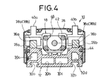
図1は、本発明の実施例に係る電動アクチュエータの斜視図、図2は、図1に示す電動アクチュエータの要部分解斜視図、図3は、図1に示す電動アクチュエータの一部断面側面図、図4は、図1のIV−IV線に沿った縦断面図である。
【0012】
この電動アクチュエータ10は、基本的には、図2に示されるように、長手方向に沿って長尺状に形成されたフレーム12と、前記フレーム12の上面部に画成された溝部14a、14bに略平行に固設される一対のリニアガイド16a、16bと、前記リニアガイド16a、16bに固定されてフレーム12の長手方向に沿って変位するスライドテーブル18と、フレーム12の両端部に画成された一組の段部19、21に夫々位置決めして固定される駆動ユニット20とから構成される(図2参照)。
【0013】
前記フレーム12の長手方向に沿った両端部には一組のエンドカバー22、24が夫々対向して装着され、前記フレーム12の短手方向に沿った両側面部には、一対のサイドカバー26a、26bが夫々対向して装着され、前記フレーム12の上面部にはトップカバー28が装着される(図1参照)。なお、前記エンドカバー22、24、サイドカバー26a、26bおよびトップカバー28は、夫々フレーム12に着脱自在に設けられている。さらに、前記フレーム12には、断面略矩形状の第1〜第4の貫通孔30a〜30dが画成され(図4参照)、前記第1〜第4貫通孔30a〜30dは、駆動ユニット20の配線通路等として用いられる。フレーム12の底面部には、長手方向に沿って延在し他の装置等に連結するための断面略T字状の溝部32a、32bが画成されている。
【0014】
リニアガイド16a、16bは、図2に示されるように、夫々略同一形状に形成され、所定間隔離間する複数の固定用孔部34を介してフレーム12の溝部14a、14bに位置決めされて固設される長尺な一対のガイドレール36a、36bと、夫々のガイドレール36a、36bの長手方向に沿って摺動変位する一対のガイドブロック38a、38bとから構成される。前記ガイドレール36a、36bとガイドブロック38a、38bとの摺動部位には、ボール等の図示しない転動部材が環状通路内に配設され、ガイドブロック38a、38bをガイドレール36a、36bに沿って円滑に変位させることができる。
【0015】
スライドテーブル18は、図2および図4に示されるように、一対のガイドブロック38a、38bに夫々ねじ止めして固定され、所定間隔離間して略平行に形成された固定ブロック40a、40bと、前記固定ブロック40a、40bの間に一体的に結合され、断面略円弧状を呈する保持ブロック42とから構成される。前記保持ブロック42の上面部には、駆動ユニット20を構成するボールねじ44が挿通可能な幅からなる間隙46が画成され、前記間隙46に連続して略円形状の開口部が画成されている(図2、図4参照)。
【0016】
駆動ユニット20は、図2並びに図3に示されるように、ボールねじ44(駆動力伝達手段)の両端部に夫々同軸に設けられたモータ部48およびエンコーダ部50と、前記モータ部48とエンコーダ部50との間に設けられボールねじ44に螺着されて軸線方向に沿って変位する係合ブロック52とが一体的にユニット化されて構成されている。前記係合ブロック52には円柱部54が設けられ、前記円柱部54は取付用孔部56を介して保持ブロック42の開口部に装着される。なお、送りねじとして機能するボールねじ44に代替して、図示しないタイミングベルト等を用いてもよい。
【0017】
モータ部48は、図5に示されるように、ねじ58を介してフレーム12の段部19に固定されるとともに、図示しない位置決めピンを挿入してフレーム12の中心に位置決めされるモータ固定用ブロック60と、前記モータ固定用ブロック60と一体的に連結される断面略矩形状のケーシング62とを含む。前記ケーシング62の外周部にはステータ64が設けられ、前記ステータ64の内壁面にコイルが巻回されたステータコイル部66が設けられている。前記ケーシング62内には、軸線方向に沿って延在するボールねじ44の端部がベアリング部材68によって支持され、該ボールねじ44の終端部にはロータ70が止めねじ72を介して保持されている。
【0018】
エンコーダ部50は、図6に示されるように、ボールねじ44の端部近傍をベアリング部材74を介して回動自在に支持するとともに、ねじ76を介してフレーム12の段部21に固定されるエンコーダ固定用ブロック78と、連結部材80、82を介して前記エンコーダ固定用ブロック78に連結され、モータの回転数または回転角度等を検出するエンコーダ本体84とから構成される。この場合、前記エンコーダ本体84はエンコーダ固定用ブロック78と一体的に連結され、且つ該エンコーダ固定用ブロック78によって保持されている。
【0019】
なお、駆動ユニット20は、モータ部48およびエンコーダ部50を夫々フレーム12の両端部に画成された段部19、21に位置決めして固定することにより、ボールねじ44とガイドレール36a、36bとの平行精度を確保することができる。さらに、モータ固定用ブロック60およびエンコーダ固定用ブロック78に夫々画成された位置決め用孔部(図示せず)とフレーム12の段部19、21に夫々画成された位置決め用孔部86、88(図2参照)とに図示しない位置決めピンを挿通することにより、前記モータ固定用ブロック60およびエンコーダ固定用ブロック78を夫々フレームの中心に位置決めすることができる。
【0020】
また、前記駆動ユニット20では、モータ部48、ボールねじ44およびエンコーダ部50をユニットとして構成しているが、例えば、図示しないステッピングモータ等のパルスモータを用いることにより、モータ部48およびボールねじ44のみをユニットとして構成してもよい。
【0021】
さらに、エンコーダ本体84に代替して、エンコーダ固定用ブロック78にリミットスイッチ等のセンサを設ける構成を採用することも可能である。
【0022】
本発明の実施例に係る電動アクチュエータ10は基本的には以上のように構成されるものであり、次にその動作並びに作用効果について説明する。
【0023】
先ず、電動アクチュエータ10の組み付け工程について説明する。
【0024】
図2に示されるように、フレーム12の溝部14a、14bにリニアガイド16a、16bを位置決めして固設する。続いて、前記リニアガイド16a、16bを構成するガイドブロック38a、38bに沿ってスライドテーブル18の固定ブロック40a、40bをねじ止めする。次に、予め、単一の部品として製造された駆動ユニット20の係合ブロック52をスライドテーブル18の保持ブロック42に嵌合する。この場合、保持ブロック42の間隙46を介してボールねじ44を挿通した後、軸線方向に沿ってボールねじ44を移動させることにより、保持ブロック42の開口部に円柱部54を嵌着することができる。
【0025】
続いて、前記駆動ユニット20を構成するモータ部48およびエンコーダ部50をフレーム12に位置決めして固定する。すなわち、モータ固定用ブロック60およびエンコーダ固定用ブロック78をフレーム12の段部19、21に位置決めして、ボールねじ44とガイドレール36a、36bとの平行精度を確保した後、図示しない位置決めピンによってモータ固定用ブロック60およびエンコーダ固定用ブロック78をフレーム12の中心に位置決めして固定することができる。
【0026】
このように、一対のリニアガイド16a、16b、スライドテーブル18および駆動ユニット20をフレーム12の上面方向から簡便に組み付けた後、前記フレーム12にエンドカバー22、24、サイドカバー26a、26bおよびトップカバー28を装着する。なお、ユーザーの用途に応じて前記各種のカバーを装着せずに、フレーム12が露呈した状態で使用することも可能である。
【0027】
このように組み付けられた電動アクチュエータ10は、図示しない電源を付勢してモータ部48を駆動させ、モータ軸として機能するボールねじ44を回動させる。この場合、モータの回転数または回転角度等はボールねじ44の端部に設けられたエンコーダ本体84によって検出され、前記検出信号は貫通孔30a〜30dに挿入されたリード線を通じて図示しないコントローラに導入される。
【0028】
前記ボールねじ44の回転運動は、該ボールねじ44に螺着された係合ブロック52に伝達され、前記係合ブロック52を保持するスライドテーブル18がリニアガイド16a、16bに沿って円滑に直線状に変位する。
【0029】
以上のように、本実施例に係る電動アクチュエータ10では、ボールねじ44の両端部に夫々モータ部48とエンコーダ部50とを同軸に且つ一体的に設けるとともに、モータ部48、エンコーダ部50、ボールねじ44および係合ブロック52からなる構成要素を一体化した駆動ユニット20として構成している。このため、各構成要素毎に組み付け作業を行っていた従来技術と比較して、本実例に係る電動アクチュエータ10では、組み付け工数を削減して製造コストの低減化を図ることが可能となる。
【0030】
前記駆動ユニット20がユニット化されることにより、大量生産することが可能となるとともに、何らかの原因で故障が発生した場合には、簡便にフレーム12から離脱させることにより、新たな駆動ユニット20と容易に交換することができる。
【0031】
また、本実施例に係る電動アクチュエータ10では、カップリング部材を用いることなくモータ軸とボールねじ44とを同軸に形成していることから、前記カップリング部材が占有する長さだけスライドテーブル18の移動範囲が増長され、この結果、フレーム12の略全長にわたってスライドテーブル18を移動させることが可能となる。
【0032】
【発明の効果】
本発明に係る電動アクチュエータによれば、以下の効果が得られる。
【0033】
すなわち、モータ部、ボールねじ、エンコーダ部および係合ブロックが一体的に組み付けられた駆動ユニットとして構成し、前記モータ部およびエンコーダ部を前記フレームの両端部に形成された一組の段部にそれぞれ位置決めして前記駆動ユニットを該フレームに固定することにより、電動アクチュエータを製造する際の組み付け工数を削減し、製造コストの低減化を図ることができる。
【0034】
また、従来技術のようにカップリング部材を用いることなく、ボールねじの一端部および他端部にそれぞれモータ部およびエンコーダ部を一体化しているため、前記カップリング部材を配設するスペースを削減してスライドテーブルが移動する範囲を増長させ、フレームの略全長にわたって該スライドテーブルを移動させることが可能となる。
【図面の簡単な説明】
【図1】本発明の実施例に係る電動アクチュエータの斜視図である。
【図2】図1に示す電動アクチュエータの要部分解斜視図である。
【図3】図1に示す電動アクチュエータの一部断面側面図である。
【図4】図1に示すIV−IV線に沿った縦断面図である。
【図5】駆動ユニットを構成するモータ部の部分断面図である。
【図6】駆動ユニットを構成するエンコーダ部の部分断面図である。
【符号の説明】
10…電動アクチュエータ 12…フレーム
14a、14b…溝部 16a、16b…リニアガイド
18…スライドテーブル 19、21…段部
20…駆動ユニット 36a、36b…ガイドレール
38a、38b…ガイドブロック 40a、40b…固定ブロック
42…保持ブロック 48…モータ部
50…エンコーダ部 52…係合ブロック
54…円柱部 60…モータ固定用ブロック
78…エンコーダ固定用ブロック 84…エンコーダ本体[0001]
[Industrial application fields]
The present invention conveys the workpiece by transmitting the rotational driving force of the motor unit provided in the frame to the slide table via a ball screw , and displacing the slide table along a guide rail fixed to the frame. The present invention relates to an electric actuator.
[0002]
[Prior art]
Conventionally, for example, an electric actuator has been used as a means for conveying a workpiece. This electric actuator basically includes an electric motor disposed in the frame of the actuator, and a driving force transmission means such as a ball screw that converts the rotational driving force of the electric motor into a linear motion and transmits it to other members. And a slide table that is displaced along the longitudinal direction of the frame via the driving force transmission means, and each component is formed of a single part and assembled to each component. ing.
[0003]
A coupling member is interposed between the electric motor and the ball screw to connect the motor shaft and the ball screw coaxially and transmit the rotational motion of the motor shaft to the ball screw. In addition, a support block or the like that pivotally supports the ball screw is provided at one end of the ball screw, and further, close to or integrated with the electric motor. An encoder that detects an angle or the like is provided.
[0004]
[Problems to be solved by the invention]
However, in the electric actuator according to the above-described prior art, an extra space other than the moving range of the slide table is required in the overall length in the longitudinal direction of the frame due to the provision of the coupling member and the like, and the overall length in the longitudinal direction of the frame There is an inconvenience that the moving range of the slide table cannot be set.
[0005]
Further, since various components in the electric actuator are each formed of a single part, there is a disadvantage that a lot of time is required for the assembly man-hour and the manufacturing cost increases.
[0006]
The present invention has been made to overcome the above-described disadvantages. The moving range of the slide table is increased so that the moving range and the frame length substantially coincide with each other, and the moving table is arranged on the frame. It is an object of the present invention to provide an electric actuator capable of reducing the assembly cost by unitizing the constituent elements to reduce the manufacturing cost.
[0007]
[Means for Solving the Problems]
To achieve the above object, the present invention comprises a frame extending along the longitudinal direction;
A pair of linear guides fixed in parallel along the groove formed in the frame;
A slide table that is displaced along the longitudinal direction of the frame under the guiding action of the linear guide;
An end cover detachably mounted opposite to each other at both ends along the longitudinal direction of the frame;
A side cover that is detachably mounted opposite to both side surfaces orthogonal to the longitudinal direction of the frame;
A top cover provided on the upper surface portion along the longitudinal direction of the frame and detachably mounted via the end cover;
A motor unit is integrally provided at one end of the ball screw, and an encoder unit for detecting a rotation speed or a rotation angle of the motor unit is integrally provided at the other end of the ball screw. between the said screwed to the ball screw engagement blocks displaced in the axial direction of the ball screw is disposed, said motor unit, said ball screw, said encoder unit and said engagement block A drive unit that is integrally assembled ; and
A screw member for fixing the motor part to the frame;
The motor unit includes a casing, and a stator wound with a coil and fixed to the casing;
The encoder unit includes an encoder fixing block; a bearing member provided in the encoder fixing block and rotatably supporting the ball screw;
With
The frame is provided with a through-hole having a substantially rectangular cross section that penetrates along the longitudinal direction and is a wiring passage of the drive unit.
When assembling the drive unit to the frame, the motor unit and an encoder unit, by being positioned respectively on a pair of stepped portions formed at both end portions of the frame, pre-fixed linear guide in the frame de parallel accuracy of the ball screw of the drive unit is secured,
The slide table includes a pair of fixed blocks formed in parallel at a predetermined interval, and a holding block integrally coupled between the pair of fixed blocks. The driving block includes the driving unit. when assembled to the frame, the ball screw which can be inserted a gap is formed, characterized in Rukoto.
[0009]
[Action]
The electric actuator according to the present invention includes the drive unit in which the motor unit, the ball screw, the encoder unit, and the engagement block are integrally assembled, so that the drive unit can be easily assembled to the frame. When assembling the drive unit to the frame, by the motor unit and an encoder unit is positioned respectively on a pair of stepped portions formed at both end portions of the frame, pre-fixed linear guide in the frame And the parallel accuracy of the ball screw of the drive unit are ensured. As a result, the assembly work of these members can be performed efficiently in a short time. Further, according to the present invention, by providing a gap through which the ball screw can be inserted in the holding block constituting the slide table, the drive unit in which the motor unit, the ball screw, the encoder unit, and the engagement block are integrally assembled to the frame. When assembled, the engagement block can be easily assembled to the holding block of the slide table.
[0010]
【Example】
Next, a preferred embodiment of the electric actuator according to the present invention will be given and described in detail below with reference to the accompanying drawings.
[0011]
1 is a perspective view of an electric actuator according to an embodiment of the present invention, FIG. 2 is an exploded perspective view of a main part of the electric actuator shown in FIG. 1, and FIG. 3 is a partial cross-sectional side view of the electric actuator shown in FIG. 4 is a longitudinal sectional view taken along line IV-IV in FIG.
[0012]
As shown in FIG. 2, the
[0013]
A pair of
[0014]
As shown in FIG. 2, the
[0015]
As shown in FIGS. 2 and 4, the slide table 18 is fixed to the pair of guide blocks 38 a and 38 b by screwing, and fixed
[0016]
As shown in FIGS. 2 and 3, the
[0017]
As shown in FIG. 5, the
[0018]
As shown in FIG. 6, the
[0019]
The
[0020]
In the
[0021]
Further, instead of the encoder
[0022]
The
[0023]
First, the assembly process of the
[0024]
As shown in FIG. 2, the
[0025]
Subsequently, the
[0026]
Thus, after the pair of
[0027]
The
[0028]
The rotational movement of the
[0029]
As described above, in the
[0030]
When the
[0031]
Further, in the
[0032]
【The invention's effect】
According to the electric actuator of the present invention, the following effects can be obtained.
[0033]
That is, the motor unit, the ball screw, the encoder unit, and the engagement block are configured as a drive unit integrally assembled, and the motor unit and the encoder unit are respectively provided in a set of stepped portions formed at both ends of the frame. the will lock to the frame of the drive unit and positioned to reduce the assembly man-hours in manufacturing the electric actuator, Ru can be reduced in the manufacturing cost.
[0034]
Further, since the motor unit and the encoder unit are integrated with one end and the other end of the ball screw without using a coupling member as in the prior art, the space for arranging the coupling member is reduced. Thus, the range in which the slide table moves can be increased, and the slide table can be moved over substantially the entire length of the frame .
[Brief description of the drawings]
FIG. 1 is a perspective view of an electric actuator according to an embodiment of the present invention.
FIG. 2 is an exploded perspective view of a main part of the electric actuator shown in FIG.
FIG. 3 is a partial sectional side view of the electric actuator shown in FIG. 1;
4 is a longitudinal sectional view taken along line IV-IV shown in FIG.
FIG. 5 is a partial cross-sectional view of a motor unit constituting the drive unit.
FIG. 6 is a partial cross-sectional view of an encoder unit constituting the drive unit.
[Explanation of symbols]
DESCRIPTION OF
Claims (1)
前記フレームに形成された溝部に沿って平行に固設される一対のリニアガイドと、
前記リニアガイドの案内作用下に前記フレームの長手方向に沿って変位するスライドテーブルと、
前記フレームの長手方向に沿った両端部に相互に対向して着脱自在に装着されるエンドカバーと、
前記フレームの長手方向と直交する両側面部に相互に対向して着脱自在に装着されるサイドカバーと、
前記フレームの長手方向に沿った上面部に設けられ、前記エンドカバーを介して着脱自在に装着されるトップカバーと、
前記ボールねじの一端部にモータ部を一体的に設けるとともに、前記ボールねじの他端部に該モータ部の回転数または回転角度を検出するエンコーダ部を一体的に設け、前記モータ部とエンコーダ部との間には、前記ボールねじに螺着されて該ボールねじの軸線方向に沿って変位する係合ブロックが配設され、前記モータ部、前記ボールねじ、前記エンコーダ部および前記係合ブロックが一体的に組み付けられて設けられた駆動ユニットと、
前記モータ部を前記フレームに固定するねじ部材と、
前記モータ部はケーシングを含み、コイルが巻回され前記ケーシングに固定されたステータと、
前記エンコーダ部はエンコーダ固定用ブロックを含み、前記エンコーダ固定用ブロックに設けられ前記ボールねじを回転自在に支持するベアリング部材と、
を備え、
前記フレームには、長手方向に沿って貫通し、前記駆動ユニットの配線通路である断面略矩形状の貫通孔が設けられ、
前記駆動ユニットを前記フレームに組み付ける際、前記モータ部およびエンコーダ部は、前記フレームの両端部に形成された一組の段部にそれぞれ位置決めされることにより、前記フレーム内に予め固定されたリニアガイドと前記駆動ユニットのボールねじとの平行精度が確保され、
前記スライドテーブルは、所定間隔離間して平行に形成された一対の固定ブロックと、前記一対の固定ブロックの間に一体的に結合された保持ブロックとからなり、前記保持ブロックには、前記駆動ユニットを前記フレームに組み付ける際、前記ボールねじが挿通可能な間隙が形成されることを特徴とする電動アクチュエータ。 A frame extending along the longitudinal direction;
A pair of linear guides fixed in parallel along the groove formed in the frame;
A slide table that is displaced along the longitudinal direction of the frame under the guiding action of the linear guide;
An end cover detachably mounted opposite to each other at both ends along the longitudinal direction of the frame;
A side cover that is detachably mounted opposite to both side surfaces orthogonal to the longitudinal direction of the frame;
A top cover provided on the upper surface portion along the longitudinal direction of the frame and detachably mounted via the end cover;
A motor unit is integrally provided at one end of the ball screw, and an encoder unit for detecting a rotation speed or a rotation angle of the motor unit is integrally provided at the other end of the ball screw. between the said screwed to the ball screw engagement blocks displaced in the axial direction of the ball screw is disposed, said motor unit, said ball screw, said encoder unit and said engagement block A drive unit that is integrally assembled ; and
A screw member for fixing the motor part to the frame;
The motor unit includes a casing, and a stator wound with a coil and fixed to the casing;
The encoder unit includes an encoder fixing block; a bearing member provided in the encoder fixing block and rotatably supporting the ball screw;
With
The frame is provided with a through-hole having a substantially rectangular cross section that penetrates along the longitudinal direction and is a wiring passage of the drive unit.
When assembling the drive unit to the frame, the motor unit and an encoder unit, by being positioned respectively on a pair of stepped portions formed at both end portions of the frame, pre-fixed linear guide in the frame de parallel accuracy of the ball screw of the drive unit is secured,
The slide table includes a pair of fixed blocks formed in parallel at a predetermined interval, and a holding block integrally coupled between the pair of fixed blocks. The driving block includes the driving unit. when assembling the said frame, the electric actuator, wherein Rukoto said ball screw which can be inserted a gap is formed.
Priority Applications (5)
| Application Number | Priority Date | Filing Date | Title |
|---|---|---|---|
| JP15711694A JP3710098B2 (en) | 1994-07-08 | 1994-07-08 | Electric actuator |
| KR1019950007717A KR100190595B1 (en) | 1994-04-05 | 1995-04-03 | Guide rail for an electric actuator |
| DE19512080A DE19512080C2 (en) | 1994-04-05 | 1995-04-03 | Electrical actuator |
| US08/415,363 US5637940A (en) | 1994-04-05 | 1995-04-03 | Electric Actuator |
| US08/870,697 US5811901A (en) | 1994-04-05 | 1997-06-09 | Guide rail for an electric actuator |
Applications Claiming Priority (1)
| Application Number | Priority Date | Filing Date | Title |
|---|---|---|---|
| JP15711694A JP3710098B2 (en) | 1994-07-08 | 1994-07-08 | Electric actuator |
Publications (2)
| Publication Number | Publication Date |
|---|---|
| JPH0833264A JPH0833264A (en) | 1996-02-02 |
| JP3710098B2 true JP3710098B2 (en) | 2005-10-26 |
Family
ID=15642572
Family Applications (1)
| Application Number | Title | Priority Date | Filing Date |
|---|---|---|---|
| JP15711694A Expired - Fee Related JP3710098B2 (en) | 1994-04-05 | 1994-07-08 | Electric actuator |
Country Status (1)
| Country | Link |
|---|---|
| JP (1) | JP3710098B2 (en) |
Cited By (1)
| Publication number | Priority date | Publication date | Assignee | Title |
|---|---|---|---|---|
| KR200463349Y1 (en) | 2011-02-11 | 2012-10-30 | 김병찬 | Transfer Device for precision micro-positioner |
Families Citing this family (1)
| Publication number | Priority date | Publication date | Assignee | Title |
|---|---|---|---|---|
| JP3488686B2 (en) * | 2000-12-05 | 2004-01-19 | Smc株式会社 | Actuator |
-
1994
- 1994-07-08 JP JP15711694A patent/JP3710098B2/en not_active Expired - Fee Related
Cited By (1)
| Publication number | Priority date | Publication date | Assignee | Title |
|---|---|---|---|---|
| KR200463349Y1 (en) | 2011-02-11 | 2012-10-30 | 김병찬 | Transfer Device for precision micro-positioner |
Also Published As
| Publication number | Publication date |
|---|---|
| JPH0833264A (en) | 1996-02-02 |
Similar Documents
| Publication | Publication Date | Title |
|---|---|---|
| JP3695784B2 (en) | Electric actuator | |
| JP3899617B2 (en) | Actuator | |
| US5637940A (en) | Electric Actuator | |
| JPH10184844A (en) | Electric actuator | |
| KR0134901Y1 (en) | Small-sized motor with worm reduction gear | |
| JP2535248Y2 (en) | XY table device | |
| KR20030095250A (en) | Actuator | |
| KR20010071466A (en) | Electromotive drive system, especially a power window drive system for a motor vehicle | |
| JP3710098B2 (en) | Electric actuator | |
| ES2171362T1 (en) | EXTRUSION DEVICE | |
| IL156995A0 (en) | Design for frameless cartridge motors | |
| JPH09248785A (en) | Positioning device | |
| JP4866731B2 (en) | General-purpose actuators used especially for dashboards | |
| JP3798683B2 (en) | Rotation detector for small motor with worm reducer | |
| JPH11206091A (en) | Abducting synchronous motor | |
| CN112018942B (en) | Leg driving motor of foot type robot | |
| JP2001106330A (en) | Belt driving motor pulley, belt conveyer apparatus, and motor roller | |
| CN111769485A (en) | Bearing support type rotary unit and automatic stripper for insulated overhead conductor | |
| JP2000065179A (en) | Linear motor | |
| JP2003014069A (en) | Shaft connecting structure in uniaxial robot | |
| CN111306270A (en) | Ball and motor integrated driving electric cylinder | |
| JPH07284242A (en) | Electrically-driven actuator | |
| JPH082161B2 (en) | Combined servo motor | |
| JP4751088B2 (en) | Linear motion device | |
| CN211820608U (en) | Ball and motor integrated driving electric cylinder |
Legal Events
| Date | Code | Title | Description |
|---|---|---|---|
| A521 | Written amendment |
Free format text: JAPANESE INTERMEDIATE CODE: A523 Effective date: 20050627 |
|
| A61 | First payment of annual fees (during grant procedure) |
Free format text: JAPANESE INTERMEDIATE CODE: A61 Effective date: 20050808 |
|
| R150 | Certificate of patent or registration of utility model |
Free format text: JAPANESE INTERMEDIATE CODE: R150 |
|
| FPAY | Renewal fee payment (event date is renewal date of database) |
Free format text: PAYMENT UNTIL: 20090819 Year of fee payment: 4 |
|
| FPAY | Renewal fee payment (event date is renewal date of database) |
Free format text: PAYMENT UNTIL: 20100819 Year of fee payment: 5 |
|
| LAPS | Cancellation because of no payment of annual fees |