JP3708317B2 - Photocatalytic air purifier - Google Patents
Photocatalytic air purifier Download PDFInfo
- Publication number
- JP3708317B2 JP3708317B2 JP00517798A JP517798A JP3708317B2 JP 3708317 B2 JP3708317 B2 JP 3708317B2 JP 00517798 A JP00517798 A JP 00517798A JP 517798 A JP517798 A JP 517798A JP 3708317 B2 JP3708317 B2 JP 3708317B2
- Authority
- JP
- Japan
- Prior art keywords
- air
- photocatalytic
- air flow
- ultraviolet
- housing
- Prior art date
- Legal status (The legal status is an assumption and is not a legal conclusion. Google has not performed a legal analysis and makes no representation as to the accuracy of the status listed.)
- Expired - Fee Related
Links
- 230000001699 photocatalysis Effects 0.000 title claims description 39
- 239000011941 photocatalyst Substances 0.000 claims description 8
- 230000001678 irradiating effect Effects 0.000 claims description 3
- 230000007423 decrease Effects 0.000 description 8
- 238000004887 air purification Methods 0.000 description 5
- 230000000694 effects Effects 0.000 description 5
- 239000000463 material Substances 0.000 description 5
- 238000010586 diagram Methods 0.000 description 3
- 239000011347 resin Substances 0.000 description 3
- 229920005989 resin Polymers 0.000 description 3
- 230000002265 prevention Effects 0.000 description 2
- 239000004925 Acrylic resin Substances 0.000 description 1
- 229920000178 Acrylic resin Polymers 0.000 description 1
- GWEVSGVZZGPLCZ-UHFFFAOYSA-N Titan oxide Chemical compound O=[Ti]=O GWEVSGVZZGPLCZ-UHFFFAOYSA-N 0.000 description 1
- BZHJMEDXRYGGRV-UHFFFAOYSA-N Vinyl chloride Chemical compound ClC=C BZHJMEDXRYGGRV-UHFFFAOYSA-N 0.000 description 1
- 238000010521 absorption reaction Methods 0.000 description 1
- 230000003213 activating effect Effects 0.000 description 1
- 230000015572 biosynthetic process Effects 0.000 description 1
- 230000000903 blocking effect Effects 0.000 description 1
- 238000007664 blowing Methods 0.000 description 1
- 230000003197 catalytic effect Effects 0.000 description 1
- 239000002131 composite material Substances 0.000 description 1
- 230000003247 decreasing effect Effects 0.000 description 1
- 239000011521 glass Substances 0.000 description 1
- 238000005338 heat storage Methods 0.000 description 1
- 238000009413 insulation Methods 0.000 description 1
- QSHDDOUJBYECFT-UHFFFAOYSA-N mercury Chemical compound [Hg] QSHDDOUJBYECFT-UHFFFAOYSA-N 0.000 description 1
- 230000003287 optical effect Effects 0.000 description 1
- 238000010422 painting Methods 0.000 description 1
- 230000002093 peripheral effect Effects 0.000 description 1
- 238000011144 upstream manufacturing Methods 0.000 description 1
- 238000007740 vapor deposition Methods 0.000 description 1
- 238000009423 ventilation Methods 0.000 description 1
- 230000003313 weakening effect Effects 0.000 description 1
Images

Classifications
-
- B—PERFORMING OPERATIONS; TRANSPORTING
- B60—VEHICLES IN GENERAL
- B60H—ARRANGEMENTS OF HEATING, COOLING, VENTILATING OR OTHER AIR-TREATING DEVICES SPECIALLY ADAPTED FOR PASSENGER OR GOODS SPACES OF VEHICLES
- B60H3/00—Other air-treating devices
- B60H3/06—Filtering
- B60H2003/0675—Photocatalytic filters
Landscapes
- Disinfection, Sterilisation Or Deodorisation Of Air (AREA)
- Exhaust Gas Treatment By Means Of Catalyst (AREA)
- Catalysts (AREA)
- Air-Conditioning For Vehicles (AREA)
Description
【0001】
【発明の属する技術分野】
この発明は光触媒式空気清浄器に関する。
【0002】
【従来の技術】
特開平8−268134号には光触媒式空気清浄器の一例が示されており、この光触媒式空気清浄器は、紫外線発生管及びこの外周側へ同芯状に配置された直管状カバーとを備え、この直管状カバーの内面には光触媒が坦持されるとともに、これら紫外線発生管及び直管状カバーはそれぞれ各長手方向が送風ファンによって形成された空気流の方向と略平行するように配設されている。
【0003】
【発明が解決しようとする課題】
ところで、光触媒による空気浄化効率は光触媒に照射される紫外線の光量により左右されるが、紫外線発生管の温度が低下すると紫外線の光量が低下することがある。上記従来例では空気流が紫外線発生管へ直接接触することにより温度低下が生じる。但し、空気流を弱くすると空気浄化効率が低下する。したがって空気流を減少させずにかつ紫外線の光量低下を防止することが空気浄化効率の向上に有効である。
【0004】
一方、紫外線発生管の温度が上昇しすぎると紫外線発生管の水銀蒸気圧が過大となり、紫外線の2次吸収により光量が低下してしまうこともある。そこで本願発明は係る諸問題の解決を目的とする。
【0005】
【課題を解決するための手段】
上記課題を解決するため本願の光触媒式空気清浄器に係る請求項1の発明は、外気をハウジング内へ取り込んで光触媒式フィルタへ向かう空気流を形成し、この空気流が光触媒式フィルタを通過することにより空気を浄化する光触媒式空気清浄器において、前記光触媒式フィルタに向かって紫外線を照射するための紫外線発生管と、その周囲を覆う円筒状で紫外線を透過する遮風部材とを備え、これらを前記ハウジング内の空気流中に配置するとともに、
この遮風部材の空気流に対する背面部側に開口部を設けたことを特徴とする。
【0006】
請求項2の発明は、外気をハウジング内へ取り込んで光触媒式フィルタへ向かう空気流を形成し、この空気流が光触媒式フィルタを通過することにより空気を浄化する光触媒式空気清浄器において、前記光触媒式フィルタに向かって紫外線を照射するための紫外線発生管と、その周囲の一部を覆いかつ紫外線を透過する遮風部材とを備え、
これらを前記ハウジング内の空気流中に配置するとともに、
この遮風部材は空気流に対して紫外線発生管の前面側を半円状に覆うとともに、前記紫外線発生管の背面側は遮風部材を設けずに開放したことを特徴とする。
【0007】
請求項3の発明は前記請求項1又は2の発明において、前記空気流を形成する送風ファンと紫外線発生管をハウジング内へ横並びに配設し、紫外線発生管の前方に光触媒式フィルタを配設し、ハウジングの前面から外気の取り入れと清浄空気の送出を行うようにしてにして車載用に構成したことを特徴とする
【0008】
【発明の効果】
請求項1の発明によれば、紫外線発生管の周囲を覆う遮風部材を設けることにより、空気流が直接紫外線発生管へ接触しないようにしたので、空気流による紫外線発生管の温度低下を防止でき、空気流を弱くすることなく所定の紫外線発生量を確保できる。
しかも、前記遮風部材の空気流に対する背面部側に開口部を設けたことにより、紫外線発生管の過大な温度上昇を防止できる。その結果、紫外線発生管の温度を適度に維持できる。
また、遮風部材が紫外線を透過させるため、光触媒式フィルタを十分に活性化させることができる。このため、空気浄化効率の向上を図ることができる。
【0009】
請求項2の発明によれば、請求項1と同様の効果が得られる。
【0010】
請求項3の発明によれば、ハウジング内に送風ファンと紫外線発生管を横並びに配置し、紫外線発生管の前面に光触媒式フィルタを配設することにより、ハウジングの前面から外気を取り入れかつ清浄空気を送出するようにしたので、全体を薄型にでき、かつ背面側を車体側へ当接させることができるから、車載用に適した光触媒式空気清浄器が得られる。
【0011】
【発明の実施の形態】
以下、図面に基づいて実施例を説明する。図1及び図2は遮風構造の参考例に係り、図1は空気清浄器の概略構成図、図2は遮風部材部分の斜視図である。
【0012】
まず、図1に示すように、この空気清浄器は家庭用等の据え置きタイプとして構成され、ハウジング1の内部に送風ファン2、光触媒式フィルタ3及び紫外線発生部4が直線上に配設されている。
【0013】
外気はハウジング1の一面から送風ファン2により内部へ取り込まれ、光触媒式フィルタ3へ向かう空気流を形成し、光触媒式フィルタ3を通過することにより浄化され、その後、ハウジング1の他面側から送出されるようになっている。
【0014】
送風ファン2の形式は自由であり、かつ、配置場所も本実施例のように光触媒式フィルタ3の前面側(空気流の上流側をいう。以下同じ)に配置する場合のみならず、その背面側さらには紫外線発生部4の背面側等任意である。
【0015】
また、光触媒式フィルタ3と紫外線発生部4との位置関係も、どちらを前後に配置するか任意である。なお、光触媒式フィルタ3はハニカム部材等の空隙率の大きい基材に二酸化チタン(TiO2)等の光触媒を坦持させた公知のものである。
【0016】
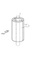
紫外線発生部4は公知の紫外線ランプ5及びその周囲を覆う円筒状の遮風部材6からなるものを一組として、これを1又は複数組用いたものであり、便宜的に3組として表示してある。
【0017】
遮風部材6は紫外線ランプ5の前面側を略円断面形状で覆う紫外線に対して透明な材料で構成された遮風部7と、背面側に設けられる同形状でかつ反射層が形成された遮風反射部8で構成されている。
【0018】
このような遮風部7は、塩化ビニール樹脂やアクリル樹脂等の紫外線に対して透明度の高い適宜樹脂材もしくは無機ガラスを用いて形成される。
【0019】
遮風反射部8側は遮風部7と同一又は異種材料で形成され、かつ表面に反射層を蒸着や塗装等で形成すること等の公知手段により得られる。
【0020】
遮風部材6は送風ファン2によって形成された空気流を紫外線ランプ5へ直接接触しにくくするように遮断するための部材であり、それ自体が空気流に接触して冷却されても紫外線ランプ5の表面温度に影響しないよう、紫外線ランプ5との間にある程度の間隔をもって配設されている。
【0021】
なお、遮風部材6を樹脂製にすることにより断熱性を高めると、遮風部材6の内側である紫外線ランプ5周囲の雰囲気温度の低下を効率よく防止できる。さらに、蓄熱作用のある材料を用いれば、温度低下防止に対して最も効果的である。
【0022】
次に、この参考例における作用を説明する。送風ファン2より取り込まれた外気は光触媒式フィルタ3へ向かう空気流となってこれを通過し、さらにこの空気流は紫外線発生部4へ流れるが、遮風部材6により紫外線ランプ5へ直接接触することなく流れ、その結果紫外線ランプ5の温度低下を防止する。
【0023】
このため、紫外線ランプ5は所定の紫外線発生量を維持し、その紫外線が光触媒式フィルタ3を照射することにより、光触媒式フィルタ3の光触媒を活性化し、十分な空気浄化効率を維持できる。
【0024】
しかも、遮風反射部8を設けることにより、紫外線をよ一層り効率的に光触媒式フィルタ3へ照射させることができるので、光触媒をさらに活性化できる。
【0025】
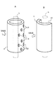
図3は遮風部材6に関する第1実施例であり、図3のAは円筒状をなす遮風部材6の周囲に比較的小さな丸穴状の開口部10を複数形成してある。遮風部材6は前参考例のような複合的なものでも全体が一様に形成されたものでもよい。
【0026】
このように開口部10を形成しても、この開口部10から内部へ入って紫外線ランプ5と接触する空気は、風量が少なくかつ勢いも弱められたものであり、送風ファン2から送風された空気流がそのままの強さで直接紫外線ランプ5へ接触しないので、紫外線ランプ5の表面温度低下を防止できる。
【0027】
そのうえ同時に、開口部10が通風口になって、遮風部材6の内側の空気と外側の空気を流通させるので、紫外線ランプ5周囲における雰囲気温度の過大上昇を防止し、その結果、紫外線ランプ5の表面温度低下防止と雰囲気温度の過大上昇防止をバランスよく達成できる。
【0028】
なお、開口部10の数又は開口度は、遮風部材6による紫外線ランプ5の過大温度上昇を防止できるように任意に設定され、好ましくは紫外線ランプ5の表面温度が使用する紫外線発生管4の紫外線発生効率の良い温度を維持するように調整する。
【0029】
また、開口部10の位置も任意に設定でき、例えば、背面側へ集中して設け、空気流が遮風部材6を直接通過して紫外線ランプ5へ接触しないように配慮することができる。この場合、開口部10から内部へ入って紫外線ランプ5と接触する空気は遮風部材6の背面側に回り込んで著しく流れの勢いを弱められたものであるから、紫外線ランプ5の表面温度低下をより防止し易くなる。
【0030】
図3のBは、開口部の変形例であり、遮風部材6が半円形断面をなして紫外線ランプ5の前面側のみを覆い、背面側が前部開放されて開口面積が著大になっている。但し、この開放部分の大きさは前記所定表面温度を維持できるように適宜調節される。このようにしても背面側に回り込む空気の流れが弱められるので前記各効果が得られるとともに、開口部10の形成並びに遮風部材6の構造が簡単になる。
【0031】
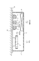
図4は車載用に構成された第2実施例であり、ハウジング1内へ送風ファン2と紫外線発生部4を横並びに配置し、紫外線発生部4の前方に光触媒式フィルタ3を配置してある。なお、紫外線発生部4に遮風部材6を用いることはこれまでのものと同様である。
【0032】
このようにすると、前記各実施例と同様な紫外線ランプ5の表面温度低下防止効果が得られるとともに、外気はハウジング1の前面から取り込まれ、略直角に方向を変えた空気流として紫外線発生部4方向へ送られ、さらに紫外線発生部4部分で再び略直角に方向を変えて光触媒式フィルタ3を通過し、その後前面から送出される。
【0033】
したがって、ハウジング1全体を薄型に配置でき、背面12を車体側の部材である、例えば、ルーフパネルや内装パネル等の内装部材13へ当接配置できるので、車載用空気清浄器として好適である。
【図面の簡単な説明】
【図1】参考例に係る空気清浄器の概略構成図
【図2】遮風部材部分の斜視図
【図3】第1実施例に係る図2と同様の図
【図4】第2実施例に係る空気清浄器の概略構成図
【符号の説明】
ハウジング1、送風ファン2、光触媒式フィルタ3、紫外線発生部4、紫外線ランプ5、遮風部材6、遮風部7、遮風反射部8、開口部10[0001]
BACKGROUND OF THE INVENTION
The present invention relates to a photocatalytic air cleaner.
[0002]
[Prior art]
Japanese Patent Application Laid-Open No. 8-268134 shows an example of a photocatalytic air purifier, and this photocatalytic air purifier includes an ultraviolet ray generating tube and a straight tubular cover arranged concentrically on the outer peripheral side. The inner surface of the straight tubular cover carries a photocatalyst, and the ultraviolet ray generating tube and the straight tubular cover are disposed so that their longitudinal directions are substantially parallel to the direction of the air flow formed by the blower fan. ing.
[0003]
[Problems to be solved by the invention]
By the way, the air purification efficiency by the photocatalyst depends on the amount of ultraviolet light irradiated to the photocatalyst, but the amount of ultraviolet light may decrease when the temperature of the ultraviolet ray generating tube decreases. In the above conventional example, the temperature is lowered by direct contact of the air flow with the ultraviolet ray generating tube. However, if the air flow is weakened, the air purification efficiency decreases. Therefore, it is effective for improving the air purification efficiency to prevent the decrease in the amount of ultraviolet light without reducing the air flow.
[0004]
On the other hand, if the temperature of the ultraviolet ray generating tube rises too much, the mercury vapor pressure in the ultraviolet ray generating tube becomes excessive, and the amount of light may decrease due to secondary absorption of ultraviolet rays. Accordingly, the present invention aims to solve such problems.
[0005]
[Means for Solving the Problems]
In order to solve the above-mentioned problem, the invention of
An opening is provided on the back side of the wind shield member with respect to the air flow .
[0006]
According to a second aspect of the present invention, there is provided a photocatalytic air purifier which purifies air by taking outside air into a housing to form an air flow toward the photocatalytic filter, and the air flow passes through the photocatalytic filter. An ultraviolet ray generating tube for irradiating ultraviolet rays toward the filter, and a wind shielding member that covers a part of the periphery and transmits ultraviolet rays,
While placing these in the air flow in the housing,
The wind shield member is characterized in that the front side of the ultraviolet ray generating tube is semicircularly covered with the air flow, and the rear side of the ultraviolet ray generating tube is opened without providing the wind shield member .
[0007]
The invention of
【The invention's effect】
According to the present invention, prevented by providing the air shield member covering the periphery of the ultraviolet ray generator tube, the air flow is prevented from contacting directly the ultraviolet generating tube, a temperature drop of the ultraviolet ray generator tube by the air flow It is possible to secure a predetermined ultraviolet ray generation amount without weakening the air flow.
In addition, by providing the opening on the back surface side of the wind-shielding member with respect to the air flow, it is possible to prevent an excessive increase in temperature of the ultraviolet ray generating tube. As a result, the temperature of the ultraviolet ray generating tube can be maintained moderately.
Further, since the wind shield member transmits ultraviolet rays, the photocatalytic filter can be sufficiently activated. For this reason, it is possible to improve the air purification efficiency.
[0009]
According to the invention of
[0010]
According to the invention of
[0011]
DETAILED DESCRIPTION OF THE INVENTION
Embodiments will be described below with reference to the drawings. 1 and 2 relate to a reference example of a wind-shielding structure , FIG. 1 is a schematic configuration diagram of an air cleaner, and FIG. 2 is a perspective view of a wind-shielding member portion.
[0012]
First, as shown in FIG. 1, this air purifier is configured as a stationary type for home use or the like, and a
[0013]
Outside air is taken into the interior of the
[0014]
The type of the
[0015]
Further, the positional relationship between the
[0016]
As the ultraviolet generator 4 one set made of a cylindrical
[0017]
The wind-
[0018]
Such a wind shielding part 7 is formed using a resin material or inorganic glass having high transparency with respect to ultraviolet rays such as vinyl chloride resin and acrylic resin.
[0019]
The wind-shielding reflection part 8 side is formed of the same or different material as the wind-shielding part 7, and is obtained by known means such as forming a reflective layer on the surface by vapor deposition or painting.
[0020]
The wind-shielding
[0021]
In addition, if the heat insulation is improved by making the
[0022]
Next, the operation of this reference example will be described. The outside air taken in from the
[0023]
For this reason, the
[0024]
In addition, by providing the wind-shielding reflecting portion 8, it is possible to irradiate the
[0025]
FIG. 3 shows a first embodiment relating to the
[0026]
Even if the
[0027]
In addition, at the same time, the
[0028]
The number of
[0029]
Also, the position of the
[0030]
FIG. 3B shows a modified example of the opening, in which the wind-shielding
[0031]
FIG. 4 shows a second embodiment configured for in-vehicle use. The
[0032]
In this way, the effect of preventing the surface temperature of the
[0033]
Therefore, the
[Brief description of the drawings]
1 is a perspective view [Figure 3] similar to FIG. 2 according to the first embodiment FIG schematic configuration diagram [2] air shield member portion of the air cleaner according to a reference example FIG. 4 a second embodiment Schematic configuration diagram of the air purifier according to the [Explanation of symbols]
Claims (3)
この遮風部材の空気流に対する背面部側に開口部を設けたことを特徴とする光触媒式空気清浄器。In a photocatalytic air purifier that takes outside air into the housing to form an air flow toward the photocatalytic filter, and purifies the air by the air flow passing through the photocatalytic filter, ultraviolet rays are directed toward the photocatalytic filter. and an ultraviolet generation tube for irradiating, and a wind shielding member which transmits ultraviolet rays at a cylindrical covering the periphery of its, with placing them in an air stream within said housing,
A photocatalytic air cleaner characterized in that an opening is provided on the back surface side of the wind shield member with respect to the air flow .
これらを前記ハウジング内の空気流中に配置するとともに、
この遮風部材は空気流に対して紫外線発生管の前面側を半円状に覆うとともに、前記紫外線発生管の背面側は遮風部材を設けずに開放したことを特徴とする光触媒式空気清浄器。 In a photocatalytic air purifier that takes outside air into the housing to form an air flow toward the photocatalytic filter, and purifies the air by the air flow passing through the photocatalytic filter, ultraviolet rays are directed toward the photocatalytic filter. An ultraviolet ray generating tube for irradiating and a wind shielding member that covers a part of the periphery and transmits ultraviolet rays,
While placing these in the air flow in the housing,
The front side of the ultraviolet ray generator tube covers a semicircular shape with respect to the air shield member airflow, the back side of the ultraviolet ray generator tube photocatalytic characterized in that it is open without providing the air shielding member air purifier.
Priority Applications (1)
| Application Number | Priority Date | Filing Date | Title |
|---|---|---|---|
| JP00517798A JP3708317B2 (en) | 1998-01-13 | 1998-01-13 | Photocatalytic air purifier |
Applications Claiming Priority (1)
| Application Number | Priority Date | Filing Date | Title |
|---|---|---|---|
| JP00517798A JP3708317B2 (en) | 1998-01-13 | 1998-01-13 | Photocatalytic air purifier |
Publications (2)
| Publication Number | Publication Date |
|---|---|
| JPH11197229A JPH11197229A (en) | 1999-07-27 |
| JP3708317B2 true JP3708317B2 (en) | 2005-10-19 |
Family
ID=11603965
Family Applications (1)
| Application Number | Title | Priority Date | Filing Date |
|---|---|---|---|
| JP00517798A Expired - Fee Related JP3708317B2 (en) | 1998-01-13 | 1998-01-13 | Photocatalytic air purifier |
Country Status (1)
| Country | Link |
|---|---|
| JP (1) | JP3708317B2 (en) |
Families Citing this family (4)
| Publication number | Priority date | Publication date | Assignee | Title |
|---|---|---|---|---|
| JP4374722B2 (en) * | 2000-04-24 | 2009-12-02 | パナソニック株式会社 | refrigerator |
| EP1556093A2 (en) * | 2002-10-21 | 2005-07-27 | UVGI Systems Limited | Cleaning of air |
| KR102590135B1 (en) | 2017-11-16 | 2023-10-18 | 삼성전자주식회사 | Filer module and air cleaner having the same |
| WO2019098776A1 (en) * | 2017-11-16 | 2019-05-23 | 삼성전자주식회사 | Filter module and air cleaner with same |
Family Cites Families (6)
| Publication number | Priority date | Publication date | Assignee | Title |
|---|---|---|---|---|
| JPS5697454A (en) * | 1979-12-26 | 1981-08-06 | Shoji Masashi | Ultraviolet ray sterilizing apparatus for interior of storage tank |
| JPH0634813Y2 (en) * | 1988-09-22 | 1994-09-14 | ウシオ電機株式会社 | Air purifier |
| JPH0725277Y2 (en) * | 1989-06-29 | 1995-06-07 | 中野 浩二 | Rectifier plate for fluid ultraviolet irradiation device |
| JP3176056B2 (en) * | 1990-09-25 | 2001-06-11 | 松下電工株式会社 | Air purifier |
| JPH08266605A (en) * | 1995-03-28 | 1996-10-15 | Seiwa Kogyo Kk | Deodorization / sterilization device |
| JPH0984866A (en) * | 1995-09-21 | 1997-03-31 | Nhk Spring Co Ltd | Deodorizing apparatus |
-
1998
- 1998-01-13 JP JP00517798A patent/JP3708317B2/en not_active Expired - Fee Related
Also Published As
| Publication number | Publication date |
|---|---|
| JPH11197229A (en) | 1999-07-27 |
Similar Documents
| Publication | Publication Date | Title |
|---|---|---|
| JP3708317B2 (en) | Photocatalytic air purifier | |
| JP4103262B2 (en) | Air purifier | |
| JP2001138737A (en) | Method for removing organic pollutant from occupant compartment of automobile by photocatalyst | |
| JP4192668B2 (en) | Vehicle interior lighting device | |
| JP3634234B2 (en) | Deodorizing device | |
| JP3230454B2 (en) | Air purifier | |
| JP3028806B2 (en) | Air purifier | |
| JP3850534B2 (en) | Deodorizing device | |
| JP2000025450A (en) | Vehicle air purifier | |
| JP2023132783A (en) | Filters, air purification mechanisms and air purification devices | |
| JP3698275B2 (en) | Air conditioner with air purification function | |
| US20030143133A1 (en) | Air cleaning apparatus | |
| JP2000237293A (en) | Photocatalytic deodorizing unit | |
| KR102597874B1 (en) | Photocatalyst Device and Air Conditioner for Vehicle | |
| JP2942549B1 (en) | Indirect lighting equipment with air purification function | |
| JP2006007806A (en) | Air cleaner for automobile | |
| JPH10309438A (en) | Gas purification equipment | |
| KR20220125496A (en) | car ventilated seat | |
| JPH10281484A (en) | Air purifier | |
| US20040247495A1 (en) | Mobile photocatalytic air cleaner | |
| JPH11342315A (en) | Photocatalytic deodorizing filter | |
| JPH0245130U (en) | ||
| JP7838247B2 (en) | Air purification device | |
| TW202142270A (en) | Photocatalytic unit and mask having the photocatalytic unit | |
| JP2005178644A (en) | Air cleaning device of car mounted type |
Legal Events
| Date | Code | Title | Description |
|---|---|---|---|
| A977 | Report on retrieval |
Free format text: JAPANESE INTERMEDIATE CODE: A971007 Effective date: 20050317 |
|
| A131 | Notification of reasons for refusal |
Free format text: JAPANESE INTERMEDIATE CODE: A131 Effective date: 20050323 |
|
| A521 | Request for written amendment filed |
Free format text: JAPANESE INTERMEDIATE CODE: A523 Effective date: 20050520 |
|
| TRDD | Decision of grant or rejection written | ||
| A01 | Written decision to grant a patent or to grant a registration (utility model) |
Free format text: JAPANESE INTERMEDIATE CODE: A01 Effective date: 20050802 |
|
| A61 | First payment of annual fees (during grant procedure) |
Free format text: JAPANESE INTERMEDIATE CODE: A61 Effective date: 20050803 |
|
| R150 | Certificate of patent or registration of utility model |
Free format text: JAPANESE INTERMEDIATE CODE: R150 |
|
| FPAY | Renewal fee payment (event date is renewal date of database) |
Free format text: PAYMENT UNTIL: 20080812 Year of fee payment: 3 |
|
| FPAY | Renewal fee payment (event date is renewal date of database) |
Free format text: PAYMENT UNTIL: 20090812 Year of fee payment: 4 |
|
| FPAY | Renewal fee payment (event date is renewal date of database) |
Free format text: PAYMENT UNTIL: 20090812 Year of fee payment: 4 |
|
| FPAY | Renewal fee payment (event date is renewal date of database) |
Free format text: PAYMENT UNTIL: 20100812 Year of fee payment: 5 |
|
| LAPS | Cancellation because of no payment of annual fees |