JP3707635B2 - Cover mounting structure - Google Patents
Cover mounting structure Download PDFInfo
- Publication number
- JP3707635B2 JP3707635B2 JP35586796A JP35586796A JP3707635B2 JP 3707635 B2 JP3707635 B2 JP 3707635B2 JP 35586796 A JP35586796 A JP 35586796A JP 35586796 A JP35586796 A JP 35586796A JP 3707635 B2 JP3707635 B2 JP 3707635B2
- Authority
- JP
- Japan
- Prior art keywords
- cover
- covers
- mounting structure
- overlapping
- equipment
- Prior art date
- Legal status (The legal status is an assumption and is not a legal conclusion. Google has not performed a legal analysis and makes no representation as to the accuracy of the status listed.)
- Expired - Fee Related
Links
Images


Landscapes
- Connection Of Plates (AREA)
- Casings For Electric Apparatus (AREA)
- Accessory Devices And Overall Control Thereof (AREA)
- Electrophotography Configuration And Component (AREA)
Description
【0001】
【発明の属する技術分野】
本発明は、画像形成装置等の機器類を覆うカバーに関し、特に、カバー同士、又はカバーと機器類の筺体やユニット(これらを総称して「カバー類」という)との取付構造に関する。
【0002】
【発明が解決しようとする課題】
従来の画像形成装置等の機器類におけるカバーは、カバーに孔や切欠を設け、その部分をネジ止めやリベット止めによって筺体に固定していた。
しかし、この方法では、ネジやリベットなどの締結部品と、それを取り付けるための作業とが必要である。また、孔や切欠とネジやリベットとの間には若干のガタツキがあるので、カバーの位置決めが正確にはできなかった。
【0003】
これに対し、カバーに爪等の引っかけ部分を設け、筐体に形成された孔や爪に係止して取り付ける方法もあった。この場合は、位置決めが正確になるという長所はあったが、爪の部分が弱く折れやすかったり、カバー自体が外しにくいという問題があった。
【0004】
図9は従来のカバーの接続部の構成を示す図である。同図に示すように従来は、コーナー部にカバーaとカバーbとの合わせ部を配置するのが通例であった。しかし、この方法をとると機器のコーナー部の角が鋭くなりすぎる。また、カバー相互は重なったり係合したりしていないので、それぞれのカバーをネジやリベットで機器類に固定しなければならず、ネジやリベット等の締結部品の数が増えてしまうという欠点があった。
【0005】
図10は、コーナー部分の一方のカバーcの接続端部をL型に構成することで角に丸みを持たせ、他方のカバーdの端部をクランク型に折曲し、ここにネジなどの締結部品を隠すことができるようにした。しかし、カバーcを板金製とした場合は、エッヂc´が露出したり、点線のように反って、実線に示す狙いの位置に来なかったりすることがあった。
【0006】
図11のように、カバーeとカバーfとが合成樹脂のモールド成型品の場合には、カバーeの接続端部が鋭角になったり、湾曲したりする「内倒れ」の現象が発生し、相手側カバーfへの取り付けが困難になるという問題があった。
【0007】
【発明が解決しようとする課題】
本発明は、上記の事実から考えられたもので、カバー類の位置決めが簡単で、締結部品を減らすことができ、取り付けや取り外しが容易なカバー類の取付構造を提供することを目的としている。また、カバー類の位置決めと同時に、ネジを使用しなくても、脱落や外れの防止ができるものを提供することを目的としている。
【0008】
【課題を解決するための手段】
上記の目的を達成するために、本発明は、複数枚で機器類の所定部分を覆うカバー類の取付構造において、隣接するカバーがコーナー部で重なり合い、該重なり合う部分の長さが10mm以上であり、かつ該重なり合う部分で外側になるカバーがその弾性力により該重なり合う部分で内側になるカバーを機器類に向けて付勢する構成、あるいは、該重なり合う部分で外側になるカバーの該部分の端部は内側に湾曲しており、該重なり合う部分で内側になるカバーの該部分の端部には、上記湾曲を矯正しつつ前記外側になるカバーの端部を案内するように、その内側方向の長さが上記湾曲幅より大きい案内斜面が形成されている構成とした。上記カバーを機器類の筺体とすることも可能である。
【0011】
【発明の実施の形態】
以下、本発明の実施例を図にしたがって以下に説明する。図1は本発明の第1の実施例で、重なり部分で外側になる板金製のカバー11の接続端部を鋭角にし、かつ湾曲させて、内倒れ構造にしている。一方、重なり部分で内側にくる板金製のカバー12の接続部はクランク型に曲げ、先端12aに案内斜面を形成している。そして、カバー11とカバー12との重なり合う長さLを、10mm以上としている。また、このとき、カバー12の重なり合う部分の幅Dが、外側のカバー11の図示する湾曲幅Wより大きくなるようにしてある。
【0012】
カバー11をカバー12のクランク型の重なり合う部分に重ねると、ここの長さが10mm以上あり、しかも、幅Dの方がWより大きいので、外側のカバー11と内側のカバー12は、必ず重なり合うことができ、従来のように、湾曲の最大部が重ならなくなって取り付けが困難になる、と言ったことが防止できる。また、先端12aが案内斜面になっているので、湾曲の大きい部分がここに乗って、この面を滑り上がり、図1(b)に示す正常な位置に納まり易くなる。そして、内倒れが矯正されることによって、外側のカバー11から内側のカバー12に対して大きな付勢力Fが働き、内側のカバー12は、ネジやリベット等の締結部品が無くても、脱落したり、はずれることがなくなる。
【0013】
図2は、図1と同じであるが、カバー13,14を合成樹脂のモールド成型品としたもので、図3は取り付け部分の斜視図である。これらの図に示すカバー13は、図1の板金製のカバーより、内倒れの程度が小さくても同じ付勢力を得ることができる。
【0014】
図4は、本発明の第2実施例を示す。同図のAカバー15は、両端に半円状の凸形状15aからなる係合部を有する。隣合うBカバー16、Cカバー17には凸形状15aに嵌合する凹形状16a,17aが形成されている。よって、Bカバー16とCカバー17が所定の位置に位置決めされることにより、Aカバー15は、締結部品用のネジ穴や位置決め用の穴等が無くても、自動的に所定の位置に位置決めされる。なお、半円状の凸形状15a、半円状の凹形状16a,17aは位置決めが可能な形状であればどのようなものでもよい。ただし、嵌合したときにガタツキができないものが望ましい。
【0015】
図5は、本発明の第3実施例である。同図に示すDカバー18は両端に一段落ち込んだ係合部18a,18aを有する。Dカバー18の両側のEカバー19、Fカバー20には、落ち込んだ係合部18a,18aを押さえる寸法形状となった被係合部19a,20aがあるため、Eカバー19、Fカバー20が固定されるとDカバー6は締結部品用の穴を有することなく脱落やはずれを防止することができる。
【0016】
なお、Dカバー18の位置決めは、Dカバー18からピン18bを突出させ筐体10の穴10aに差し込む手段等が考えられる。また、図示は省略するが、筐体10からピンを突出させ、Dカバー18に穴を開ける図示と逆の構成としてもよい。
【0017】
図4に示すBカバー16とCカバー17の被係合部16a,17aを図5に示すDカバー18の落ち込んだ係合部18aとし、Aカバー15の凸形状の係合部15aをEカバー19、Fカバー20の係合部19a,20aとすることもできる。
【0018】
図6は、一方のカバーが機器類の筺体10となった実施例である。同図において、筐体10の一部に半円形の凹形状をした被係合部10bを設けることで、凸形状の係合部21aを有するGカバー21を位置決めしたものである。筐体12の反対側にはHカバー22があり、同様に半円凹形状の被係合部22aを有する。このような構成であれば、図4の実施例におけるAカバー15と同様にGカバー21は位置決めが可能である。
【0019】
図7は、図6と類似した実施例であるが、筐体10には被係合部10cとして孔が設けてあり、Jカバー23には被係合部10cに入るピン状の係合部23aが設けてある。又、筐体10の反対側のKカバー24にはピン状の係合部24aがあり、Jカバー23には孔状の被係合部23bを設ける。Kカバー24を固定することにより、図5の実施例と同様、Jカバー23は脱落や外れを防止することができる。この例では、Jカバー23に孔を開けたが、特に締結部品を用いたわけでもなく、接続部分も隠れてしまうので外観を良くすることができる。
【0020】
さらに、係合部23aと被係合部10c、係合部24aと被係合部23bの嵌合関係を、隙間の小さいハメアイ寸法に設定すればJカバー23は位置決めも同時にされることにもなる。
【0021】
上記の実施例では、カバーがカバー同士、又は、カバーと筐体とによって挟まれる関係について説明したが、カバーの両側が筐体の場合でも本発明の構成は可能である。ただし、この場合どちらかの筐体が容易にはずせる構成になっていないと位置決めされているカバーも容易にはずすことはできない。もっとも、位置決めされているカバーが外す必要のまったくないカバーであれば、その必要もないことになる。
【0022】
さらに上記、実施例で説明したと同様のことが筐体と部品ユニットの間でもいえる。すなわち、隣合うカバーのうち一方が筐体でもう一方がユニットとなる場合である。これは、図6のHカバー22や図7のKカバー24をユニットに置き換えた構成であるため、図示を省略する。
【0023】
上記実施例では平面的乃至角部が丸く曲げられた接続部となっているカバーを図示した、図8に示す実施例、ようなコの字形状のカバー25,26でも同様の事が言える。すなわち、カバー25のカバー26との接続部には、凸型の係合部25aがあり、カバー26に形成された凹型の被係合部26aと嵌合して、位置決めされ、かつ落下や外れが防止される。
【0024】
【発明の効果】
以上に説明したように本発明によれば、カバー類の取付構造において、隣接するカバーがコーナー部で重なり合い、該重なり合う部分で外側になるカバーの該部分の端部は内側に湾曲しており、該重なり合う部分で内側になるカバーの該部分の端部には、上記湾曲を矯正しつつ前記外側になるカバーの端部を案内するように、その内側方向の長さが上記湾曲幅より大きい案内斜面が形成された構成とすると、取り付け部が湾曲していても、カバー類を容易に取り付けることができる。上記外側のカバーがその弾性力により上記内側カバーを機器類に向けて付勢するようにすれば、締結部品の点数を減らすことができる。また、締結部品の数の削減により外観(見ばえ)も良くなる。
【図面の簡単な説明】
【図1】本発明のカバー類の取付構造の実施例を示す図で、(a)はカバーの側面図、(b)は取付状態を示す図、(c)はカバーの斜視図である。
【図2】図1におけるカバーが合成樹脂のモールド製の実施例の図で、(a)はカバーの側面図、(b)は取付状態を示す図である。
【図3】図2の実施例のカバーを取り付けた状態を示す斜視図である。
【図4】カバー同士を凸形状の係合部と凹形状の被係合部で接続して取り付けた実施例の斜視図である。
【図5】両端に一段落ち込んだ係合部を有すカバーを、両側のカバーで押さえた取付構造の実施例の断面図である。
【図6】カバーと機器類の筺体とを接続して取り付けた実施例の斜視図である。
【図7】係合部と被係合部とが、突起と穴とからなる実施例の断面図である。
【図8】カバー類がコ字状をしている実施例の斜視図である。
【図9】従来のカバーの取付構造を示す図である。
【図10】従来のカバーの別の取付構造を示す図である。
【図11】従来のカバーの内倒れを説明する図で、(a)はカバー同士がうまく重ならない状態を示す側面図、(b)はカバーの内倒れ状態を示す斜視図である。
【符号の説明】
12,13 カバー
15,16,17 カバー
18,19,20 カバー
21,22 カバー
23,24 カバー
15a,18a 係合部
21a,23a,24a 係合部
16a,19a,20a 被係合部
10b,10c,22a 被係合部
23b,26a 被係合部
W 湾曲幅
L 内側のカバーの重なり合う部分の長さ
D 内側のカバーの重なり合う部分の幅[0001]
BACKGROUND OF THE INVENTION
The present invention relates to a cover that covers devices such as an image forming apparatus, and more particularly, to an attachment structure between covers, or a cover and a housing or unit of the devices (collectively referred to as “covers”).
[0002]
[Problems to be solved by the invention]
A cover in a conventional apparatus such as an image forming apparatus is provided with a hole or a notch in the cover, and the portion is fixed to the housing by screwing or riveting.
However, this method requires fastening parts such as screws and rivets and work for attaching them. Further, since there is a slight backlash between the hole or notch and the screw or rivet, the cover cannot be accurately positioned.
[0003]
On the other hand, there is a method in which hooks such as claws are provided on the cover, and the hooks are attached to holes or claws formed in the housing. In this case, there is an advantage that the positioning becomes accurate, but there is a problem that the nail portion is weak and easily broken, and the cover itself is difficult to remove.
[0004]
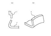
FIG. 9 is a diagram showing a configuration of a connection portion of a conventional cover. Conventionally, as shown in the figure, it has been usual to arrange a mating portion of a cover a and a cover b at a corner portion. However, if this method is used, the corners of the equipment are too sharp. Also, since the covers do not overlap or engage with each other, each cover must be fixed to the equipment with screws and rivets, which increases the number of fastening parts such as screws and rivets. there were.
[0005]
FIG. 10 shows that the connecting end portion of one cover c in the corner portion is formed in an L shape so that the corner is rounded, and the end portion of the other cover d is bent into a crank shape. The fastening parts can be hidden. However, when the cover c is made of sheet metal, the edge c ′ may be exposed or warped like a dotted line and may not come to the target position indicated by the solid line.
[0006]
As shown in FIG. 11, when the cover e and the cover f are molded products of synthetic resin, a phenomenon of “inward tilt” in which the connection end of the cover e becomes an acute angle or is curved, There was a problem that it was difficult to attach to the counterpart cover f.
[0007]
[Problems to be solved by the invention]
The present invention has been conceived from the above facts, and it is an object of the present invention to provide a cover mounting structure in which the positioning of covers is simple, the number of fastening parts can be reduced, and attachment and removal are easy. It is another object of the present invention to provide a cover that can be prevented from falling off and coming off without using screws at the same time as positioning the covers.
[0008]
[Means for Solving the Problems]
In order to achieve the above object, according to the present invention, in a cover mounting structure that covers a predetermined portion of equipment with a plurality of sheets, adjacent covers overlap at a corner portion, and the length of the overlapping portion is 10 mm or more. Ri, and configured to cover formed outside a portion where each other become heavy to urge the cover formed inwardly at a portion where mutually become heavy to equipment by its elastic force, Or, partial cover made outward at portions mutually become heavy The end of the cover is inwardly curved, and the end of the part of the cover that becomes the inner side in the overlapping part is guided to the end of the cover that becomes the outer side while correcting the curvature. A guide slope having a direction length larger than the curved width is formed . It is also possible to the top Symbol cover and the housing of the equipment.
[0011]
DETAILED DESCRIPTION OF THE INVENTION
Embodiments of the present invention will be described below with reference to the drawings. FIG. 1 shows a first embodiment of the present invention, in which a connecting end portion of a
[0012]
When the
[0013]
FIG. 2 is the same as FIG. 1 except that the
[0014]
FIG. 4 shows a second embodiment of the present invention. The A
[0015]
FIG. 5 shows a third embodiment of the present invention. The
[0016]
The positioning of the
[0017]
The engaged
[0018]
FIG. 6 shows an embodiment in which one cover is a
[0019]
FIG. 7 is an embodiment similar to FIG. 6, but the
[0020]
Furthermore, if the fitting relationship between the engaging
[0021]
In the above-described embodiment, the relationship in which the covers are sandwiched between the covers or between the cover and the casing has been described. However, the configuration of the present invention is possible even when both sides of the cover are casings. In this case, however, the positioned cover cannot be easily removed unless one of the casings is easily removable. However, if the positioned cover does not need to be removed at all, it is not necessary.
[0022]
Further, the same as described in the above embodiment can be said between the housing and the component unit. That is, one of the adjacent covers is a case and the other is a unit. Since this is a configuration in which the
[0023]
The same can be said for the U-shaped covers 25 and 26 as shown in the embodiment of FIG. 8, which illustrates a cover having a planar or corner bent connection portion in the above embodiment. That is, there is a
[0024]
【The invention's effect】
As described above, according to the present invention, in the cover mounting structure, adjacent covers overlap at the corner portion, and the end portion of the cover that is outside at the overlapping portion is curved inward, At the end of the part of the cover that becomes the inner side in the overlapping part, the length of the inner side is larger than the bending width so as to guide the end of the cover that becomes the outer side while correcting the curve. If it is set as the structure in which the slope was formed, even if the attaching part is curving, covers can be attached easily. If the outer cover urges the inner cover toward the devices by its elastic force, the number of fastening parts can be reduced. Further, the appearance (look) is improved by reducing the number of fastening parts.
[Brief description of the drawings]
1A and 1B are views showing an embodiment of a cover mounting structure according to the present invention, in which FIG. 1A is a side view of the cover, FIG. 1B is a view showing a mounting state, and FIG.
FIGS. 2A and 2B are diagrams of an embodiment in which the cover in FIG. 1 is made of a synthetic resin mold, in which FIG. 2A is a side view of the cover, and FIG.
3 is a perspective view showing a state where a cover of the embodiment of FIG. 2 is attached. FIG.
FIG. 4 is a perspective view of an embodiment in which covers are connected and connected by a convex engaging portion and a concave engaged portion.
FIG. 5 is a cross-sectional view of an embodiment of an attachment structure in which a cover having an engaging portion that is depressed at both ends is pressed by covers on both sides.
FIG. 6 is a perspective view of an embodiment in which a cover and a housing of equipment are connected and attached.
FIG. 7 is a cross-sectional view of an embodiment in which the engaging portion and the engaged portion are formed of protrusions and holes.
FIG. 8 is a perspective view of an embodiment in which covers are U-shaped.
FIG. 9 is a view showing a conventional cover mounting structure.
FIG. 10 is a view showing another mounting structure of a conventional cover.
11A and 11B are diagrams for explaining inward tilting of a conventional cover, in which FIG. 11A is a side view illustrating a state where the covers do not overlap each other, and FIG. 11B is a perspective view illustrating the inward state of the cover;
[Explanation of symbols]
12, 13
Claims (3)
Priority Applications (1)
| Application Number | Priority Date | Filing Date | Title |
|---|---|---|---|
| JP35586796A JP3707635B2 (en) | 1996-12-25 | 1996-12-25 | Cover mounting structure |
Applications Claiming Priority (1)
| Application Number | Priority Date | Filing Date | Title |
|---|---|---|---|
| JP35586796A JP3707635B2 (en) | 1996-12-25 | 1996-12-25 | Cover mounting structure |
Publications (2)
| Publication Number | Publication Date |
|---|---|
| JPH10184622A JPH10184622A (en) | 1998-07-14 |
| JP3707635B2 true JP3707635B2 (en) | 2005-10-19 |
Family
ID=18446136
Family Applications (1)
| Application Number | Title | Priority Date | Filing Date |
|---|---|---|---|
| JP35586796A Expired - Fee Related JP3707635B2 (en) | 1996-12-25 | 1996-12-25 | Cover mounting structure |
Country Status (1)
| Country | Link |
|---|---|
| JP (1) | JP3707635B2 (en) |
Families Citing this family (4)
| Publication number | Priority date | Publication date | Assignee | Title |
|---|---|---|---|---|
| JP5668372B2 (en) * | 2010-09-01 | 2015-02-12 | 株式会社リコー | Image forming apparatus |
| JP6314606B2 (en) * | 2014-03-31 | 2018-04-25 | ブラザー工業株式会社 | Sheet transport device |
| JP7484419B2 (en) * | 2020-05-25 | 2024-05-16 | 京セラドキュメントソリューションズ株式会社 | Exterior cover |
| JP7739141B2 (en) * | 2021-11-10 | 2025-09-16 | キヤノン株式会社 | Image forming device |
-
1996
- 1996-12-25 JP JP35586796A patent/JP3707635B2/en not_active Expired - Fee Related
Also Published As
| Publication number | Publication date |
|---|---|
| JPH10184622A (en) | 1998-07-14 |
Similar Documents
| Publication | Publication Date | Title |
|---|---|---|
| US5668348A (en) | CPU dissipator mounting apparatus | |
| JP3707635B2 (en) | Cover mounting structure | |
| US4074401A (en) | Snap assembly | |
| JPH1126097A (en) | Socket to be installed in panel | |
| US20040032713A1 (en) | Panel mounting apparatus | |
| JPH07122860A (en) | Electronic device housing structure | |
| JPH08107617A (en) | Cover locking structure | |
| JPH04151010A (en) | Engagingly locking structure | |
| JP5484203B2 (en) | Car equipment | |
| US6256836B1 (en) | Easy-release hinge system | |
| JP2569080Y2 (en) | Locking structure of removable cover | |
| JP6115376B2 (en) | Panel fixing structure and automatic transaction device | |
| US20210243909A1 (en) | Device casing | |
| JP4509009B2 (en) | Oil filter mounting structure and clip used therefor | |
| JP4392468B2 (en) | Picture frame | |
| JP4759951B2 (en) | Remote control device housing structure | |
| JP2878239B2 (en) | Cover device | |
| JPH11127U (en) | Rear cap for interchangeable lens | |
| JPH07202445A (en) | Lightweight housing | |
| JP6167782B2 (en) | Housing and development housing | |
| JP3045635U (en) | Detachable wiper device for iron plate telescopic cover | |
| JP3529903B2 (en) | Blindfold | |
| JPH0936567A (en) | Fitting structure | |
| JPH09207683A (en) | Housing structure | |
| JP2828498B2 (en) | Camera |
Legal Events
| Date | Code | Title | Description |
|---|---|---|---|
| A977 | Report on retrieval |
Free format text: JAPANESE INTERMEDIATE CODE: A971007 Effective date: 20041124 |
|
| A131 | Notification of reasons for refusal |
Free format text: JAPANESE INTERMEDIATE CODE: A131 Effective date: 20041202 |
|
| A521 | Written amendment |
Free format text: JAPANESE INTERMEDIATE CODE: A523 Effective date: 20050126 |
|
| A131 | Notification of reasons for refusal |
Free format text: JAPANESE INTERMEDIATE CODE: A131 Effective date: 20050517 |
|
| A521 | Written amendment |
Free format text: JAPANESE INTERMEDIATE CODE: A523 Effective date: 20050707 |
|
| TRDD | Decision of grant or rejection written | ||
| A01 | Written decision to grant a patent or to grant a registration (utility model) |
Free format text: JAPANESE INTERMEDIATE CODE: A01 Effective date: 20050728 |
|
| A61 | First payment of annual fees (during grant procedure) |
Free format text: JAPANESE INTERMEDIATE CODE: A61 Effective date: 20050728 |
|
| R150 | Certificate of patent or registration of utility model |
Free format text: JAPANESE INTERMEDIATE CODE: R150 |
|
| FPAY | Renewal fee payment (event date is renewal date of database) |
Free format text: PAYMENT UNTIL: 20080812 Year of fee payment: 3 |
|
| FPAY | Renewal fee payment (event date is renewal date of database) |
Free format text: PAYMENT UNTIL: 20090812 Year of fee payment: 4 |
|
| FPAY | Renewal fee payment (event date is renewal date of database) |
Free format text: PAYMENT UNTIL: 20090812 Year of fee payment: 4 |
|
| FPAY | Renewal fee payment (event date is renewal date of database) |
Free format text: PAYMENT UNTIL: 20100812 Year of fee payment: 5 |
|
| FPAY | Renewal fee payment (event date is renewal date of database) |
Free format text: PAYMENT UNTIL: 20100812 Year of fee payment: 5 |
|
| FPAY | Renewal fee payment (event date is renewal date of database) |
Free format text: PAYMENT UNTIL: 20110812 Year of fee payment: 6 |
|
| FPAY | Renewal fee payment (event date is renewal date of database) |
Free format text: PAYMENT UNTIL: 20110812 Year of fee payment: 6 |
|
| FPAY | Renewal fee payment (event date is renewal date of database) |
Free format text: PAYMENT UNTIL: 20120812 Year of fee payment: 7 |
|
| FPAY | Renewal fee payment (event date is renewal date of database) |
Free format text: PAYMENT UNTIL: 20120812 Year of fee payment: 7 |
|
| FPAY | Renewal fee payment (event date is renewal date of database) |
Free format text: PAYMENT UNTIL: 20130812 Year of fee payment: 8 |
|
| LAPS | Cancellation because of no payment of annual fees |