JP3707204B2 - Method for correcting read image and image reading apparatus - Google Patents
Method for correcting read image and image reading apparatus Download PDFInfo
- Publication number
- JP3707204B2 JP3707204B2 JP14134497A JP14134497A JP3707204B2 JP 3707204 B2 JP3707204 B2 JP 3707204B2 JP 14134497 A JP14134497 A JP 14134497A JP 14134497 A JP14134497 A JP 14134497A JP 3707204 B2 JP3707204 B2 JP 3707204B2
- Authority
- JP
- Japan
- Prior art keywords
- line
- image
- document
- pixels
- pixel
- Prior art date
- Legal status (The legal status is an assumption and is not a legal conclusion. Google has not performed a legal analysis and makes no representation as to the accuracy of the status listed.)
- Expired - Fee Related
Links
Images
Landscapes
- Editing Of Facsimile Originals (AREA)
Description
【0001】
【発明の属する技術分野】
本発明は、書籍や雑誌などの綴じられた原稿の読取りに好適な画像読取り装置のための読取り画像の修正方法に関する。
【0002】
【従来の技術】
ブックスキャナと呼称される画像読取り装置が商品化されている。この装置では、原稿台の上方に撮影系が配置され、原稿台と撮影系との間に高さ数十cmの開放空間が存在する。書籍や雑誌などの綴じられた原稿(これを「ブック原稿」と呼称する)の読取りに際して、ユーザーは原稿台上にブック原稿を見開いて上向きにセットする。スタートキーのオンに呼応して、ブックスキャナは照明ランプを点灯して原稿面(見開き面)の走査を開始し、読み取った画像を逐次に外部装置へ出力する。外部装置がプリンタであれば、リアルタイムで複写画像が形成される。ブックスキャナによれば、原稿台上に置いたままの状態でページをめくることができるので、多数ページの読取り作業の能率を高めることができる。
【0003】
シート原稿と違ってブック原稿では、見開いた状態を保持するために見開き面の端部を押さえておかなければならない場合が多い。その場合に、ユーザーの指や手の甲が原稿とともに撮影されてしまう。ブックスキャナの出力画像の見栄えをよくするには、指や手の像(以下「手指像」という)を消去する必要がある。
従来において、読取り画像からの手指像の抽出は、濃度又は色の判別によって行われていた。すなわち、原稿の周縁領域(余白領域)を対象に画素濃度を調べて一定濃度以上の画素からなる画像を抽出する手法(特開平6−78133号)、カラー撮影を行って撮影像から肌の色の画像を抽出する手法(特開平6−105091号)があった。原稿端縁の両側に跨がるか否かを調べたり、大きさの判別を行ったりすることにより抽出の精度を高めることができる。
【0004】
【発明が解決しようとする課題】
従来では、ユーザーの手指の表面の中に照明光が正反射して撮影系に入射するような傾斜部が存在する場合に、その傾斜部が原稿の下地に近い明るさのハイライト(色は照明光の色)となってしまい、濃度及び色のどちらによっても手指の形状を正しく検出することができないという問題があった。また、色判別では、肌の色範囲の設定が難しくマニキュアにより検出ミスの生じるおそれがあった。
濃度判別によって手指像を抽出する手法では、必要な画像の消去を避けるために、図27(A)のように、手指像の検出対象領域A8を原稿90の周囲の余白に限定する必要があった。つまり、文字や写真などが印刷される印字領域A7と重ならないように検出対象領域A8が設定されていた。このため、図27(B)のように比較的に周囲の余白が広い場合、又は図27(C)のようにページの大半が余白である場合に、ユーザーが印字を隠さないように原稿面を押さえたとしても、指が検出対象領域A8からはみ出てしまい、出力画像G91,92に指の先端部の像Ghが残ることがあった。加えて、余白に書き込まれた手書き画像、紙面の端縁部に印字された太字のノンブル(ページ番号)やインデックス(見出し)などが消去されてしまうこともあった。
【0005】
本発明は、ユーザーの手指の像を確実に消去して読取り品質を高めることを目的としている。他の目的はインデックスに代表される端縁近傍の必要な画像の消去を防止することにある。
【0006】
【課題を解決するための手段】
手指像の存在する可能性のある領域、すなわち原稿の端縁部を対象に撮影画像の画素値を調べ、互いに隣接した低輝度の画素からなり、原稿の端縁と接する領域を手指像として抽出する。抽出した手指像のみを消去すると、例えば照明光の正反射によって実際の手指像の中央部が高輝度である場合に、その高輝度の中央部が消去されずに残ることになる。したがって、抽出した手指像とそれより外側の画像を消去する。なお、2回の読取りを行うこととし、1回目の読取りで手指像を抽出して消去範囲を設定し、2回目の読取り時に以前に設定した消去範囲に対応した画像を消去してもよい。1回の読取りにおいて手指像を抽出して消去することも可能である。
【0007】
対象領域内の全ての画素、又は所定数置きのライン(一方向の画素列)に属する画素の値をライン毎に調べる。ライン配列方向における隣接の有無は、ライン方向の画素位置の重複の度合いによって判定する。画素が低輝度であるか否かの判断の基準として、対象領域全体の輝度ヒストグラムから算出した閾値を全てのラインに共通に用いる。これにより、各ライン毎にそのラインの輝度ヒストグラムから算出した閾値を個別に適用する場合と比べて、抽出される手指像の輪郭が滑らかとなり、形状の認識が容易になる。
【0008】
請求項1の発明の方法は、原稿を撮影する撮影手段が原稿台の上方に配置された上向きセッティング型の画像読取り装置における読取り画像の修正方法であって、前記撮影手段によって得られた読取り画像における原稿の端縁に相当する位置のラインを含む複数のラインを対象として、前記各ライン毎に設定値より低輝度の画素が連なった線分を検出し、
隣接するラインの線分と互いにライン方向の位置が設定画素数分以上の長さにわたって重複する前記線分の集合であって、前記端縁に相当する位置のラインの画素からなる線分を含む連結線分群を抽出し、前記読取り画像のうち、前記連結線分群におけるライン方向の各画素位置でのライン配列方向の内端に該当する画素と、これら画素より外側でかつライン方向の画素位置が同一である画素とからなる像を消去するものである。
【0009】
請求項2の発明の方法は、ライン配列方向に互いに隣接する前記線分からなり、ライン方向の両端位置が設定ライン数以上にわたって実質的に一定である線分群を、前記連結線分群から除外するものである。
【0010】
請求項3の発明の方法は、前記設定値を、前記読取り画像における前記複数のラインを包含する領域の輝度ヒストグラムに基づいて算定するものである。
請求項4の発明の方法は、前記複数のラインについて前記端縁の側から1ラインずつ順に、前記線分を検出して前記連結線分群を抽出し、抽出した前記連結線分群の前記ライン方向の各画素位置における前記ライン配列方向の内端の画素位置を記憶する処理を繰り返し、前記読取り画像のうち、最終のラインにおける前記処理が終了した時点の前記内端に該当する画素と、これら画素より外側でかつライン方向の画素位置が同一である画素とからなる像を消去するものである。
【0011】
請求項5の発明の装置は、原稿を撮影する撮影手段が原稿台の上方に配置された上向きセッティング型の画像読取り装置であって、前記撮影手段の撮像面上での原稿の端縁を検出する手段と、前記撮影手段によって得られた読取り画像における前記端縁に相当する位置のラインを含む複数のラインを対象として、前記各ライン毎に設定値より低輝度の画素が連なった線分を検出する手段と、隣接するラインの線分と互いにライン方向の位置が設定画素数分以上の長さにわたって重複する前記線分の集合であって、前記端縁に相当する位置のラインの画素からなる線分を含む連結線分群を抽出する手段と、前記読取り画像のうち、前記連結線分群におけるライン方向の各画素位置でのライン配列方向の内端に該当する画素と、これら画素より外側でかつライン方向の画素位置が同一である画素とからなる像を消去する手段とを有している。
【0012】
【発明の実施の形態】
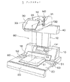
図1は本発明に係るブックスキャナ1の外観を示す斜視図、図2はブックスキャナ1による読取りの模式図、図3は原稿を押さえた状態を示す図である。
【0013】
ブックスキャナ1は、ブック原稿BDの読取りに好適な画像読取り装置であって、電源回路などを収納する本体ハウジング10、原稿を支持する暗色の原稿台20、原稿画像を電気信号に変換する撮像ユニット30、及び原稿の照明を担うランプユニット40を有している。原稿台20は本体ハウジング10の前面側に配置されている。撮像ユニット30は、原稿台20の上方に配置され、本体ハウジング10の上面から上方に延びた支柱12によって片持ち形式で支持されている。原稿台20と撮像ユニット30との間の開放空間80はブック原稿のセッティングに十分な広さを有している。ランプユニット40は、撮像ユニット30の下面の後端部に取り付けられており、原稿台20を斜め上方から照らす。
【0014】
本体ハウジング10の前面に操作パネルOPが設けられ、操作パネルOPに向かって右側の側面にメインスイッチ51が設けられている。また、本体ハウジング10の前面の下端側には、原稿の高さを検出するための投影板18が取付けられている。投影板18の前面は光沢面であり、原稿台20の上面に対する45°の傾斜面となっている。投影板18にブック原稿BDの端面S3の像が写り、その状態の投影板18が原稿画像とともに撮影される。原稿台20の左半部及び右半部にスタートキー52,53が1つずつ配置されており、前面側にアームレスト25が取付けられている。
【0015】
撮像ユニット30は、CCDアレイからなるラインセンサ31、結像レンズ32、及びミラー33を有している。ミラー33と結像レンズ32とからなる光学系OSによって、原稿画像がラインセンサ31の受光面に投影される。結像レンズ32は、前後方向に移動可能に設けられており、AF機構132によって位置決めされる。ラインセンサ31は、図示しない副走査機構の可動体(スキャナ)に取付けられており、CCD素子の配列方向を上下方向に保った状態で左右方向(副走査方向)M2に沿って平行移動をする。原稿画像の主走査方向は、原稿台20上では前後方向であり、撮像面上では上下方向である。
【0016】
ブックスキャナ1の使用に際して、ユーザーは原稿台20の上にブック原稿BDをその見開き方向が原稿台20の左右方向となるように上向きに置く。そのとき、原稿面(見開き面)S1における左右のページの境界(見開き中心)を原稿台20の左右方向の中心を示すマークに合わせるとともに、投影板18の下端縁にブック原稿BDを押し当てて前後方向の位置決めを行う。投影板18と原稿台20との境界がセッティングの基準線となっている。その基準線の中央が基準位置Ps(図2参照)である。また、ユーザーは、見開き状態を維持するために、必要に応じて図3のようにブック原稿BDの端部を手で押さえる。ここで、ブック原稿BDの手前側(原稿台の前方側)の端部を押さえることも可能であるが、原稿を押さえたままスタートキー52,53を操作するために、通常はブック原稿BDの左右方向の両端部(又は一端部)を押さえる。したがって、不要画像を消去するために行う後述の手指像の検出に際しては、ブック原稿BDの左右の両端部に注目すればよい。
【0017】
ブックスキャナ1は、1つの原稿画像に対して予備スキャンニングと本スキャンニングとを行う。予備スキャンニングの撮影情報に基づいて、見開き面S1の高さ分布・原稿サイズ・原稿の下地輝度などを測定するとともに、ユーザーによって押さえられた領域を検出する。そして、測定値及び検出結果に基づいて本スキャンニングの動作条件を設定する。本スキャンニングでは、副走査方向の進行に合わせて結像レンズ32を移動させるピント調整、画像歪みの補正、手指像を消去するマスキングなどが行われる。外部装置には本スキャンニング時の読取り画像が出力される。
【0018】
図4はブックスキャナ1の要部の機能ブロック図である。
ブックスキャナ1は、マイクロコンピュータを備えたCPU101によって制御される。CPU101は、ラインセンサ31にクロックを供給するCCD駆動回路130、副走査機構131、AF機構132、ランプユニット40の点灯制御を担うランプ制御回路140、及び画像処理回路104に動作指示を与える。CPU101には操作パネルOP、スイッチ群50、及び各種センサが接続されている。
【0019】
撮像ユニット30のラインセンサ31から出力された光電変換信号は、AD変換器102によって例えば8ビットの画像データに変換される。AD変換器102から画素配列順に出力された画像データは、画像メモリ103に一旦格納される。予備スキャンニングにおいて、画像データはCPU101及びヒストグラマ108に入力される。CPU101は、図示しない高さ分布測定部とともに、本発明の修正方法に係る3つの機能要素(端縁検出部114、線分検出部115、連結判定部116)を含んでいる。端縁検出部114は、画像データに基づいてブック原稿BDの左端及び右端を検出する。線分検出部115は、読取り画像における検出対象の各ラインの画像データを2値化し、手指像の構成要素の候補である線分を検出する。連結判定部116は、各ラインの線分がひと続きの手指像に対応するか否か、すなわち隣接するラインの線分どうしの連結の有無を判定する。これら3つの機能要素は、所定のプログラムとその実行手段とからなる。ヒストグラマ108は、読取り画像のうちの原稿面に対応した部分の画像データに基づいて、手指像の検出対象領域の輝度ヒストグラムと、各ライン毎の輝度ヒストグラムを求める。前者は線分検出部115による2値化閾値の算出に用いられ、後者は下地かぶりを防止する輝度変換の制御値である下地輝度の算出に用いられる。
【0020】
本スキャンニングにおいては、副走査方向の進行に合わせてフォーカシングが行われ、合焦状態で撮影された画像データが画像メモリ103を介して画像処理回路104に入力される。画像処理回路104は、下地輝度に応じて出力輝度を最適化する輝度変換部141、原稿面の高さ分布に応じて画像を変倍する歪み補正部142、及び手指像を含む不要画像を消去するマスキング部143を有しており、CPU101によって設定された内容のデータ処理を行う。不要画像の消去は、画素値を白地濃度値に置き換える処理である。外部装置には画像処理回路104を経た画像データが出力される。外部装置としては、プリンタ・ディスプレイ・画像メモリ装置・画像編集装置(コンピュータシステム)などがある。
【0021】
図5は原稿面の高さ分布の測定方法を説明するための図である。図中の破線は注目したラインの位置を示している。ここでは、ユーザーが原稿を押さえない状態で撮影が行われたものとする。
【0022】
読取り画像G0は、ブック原稿BDの上面の撮影像(上面像)G1、原稿台20の撮影像G20、及び投影板18の撮影像G18から構成されている。ブック原稿BDの上面とは、原稿面S1とその左右両側の端面(裾)とを合わせた表面である。撮影像G18のうちの像G181は、セッティングされたブック原稿BDの端面S3の形状を示している。撮影像G18のうちの像(端面像)G181以外の像180は、投影板18に映った背景像である。撮像面に近い被写体は遠くの被写体よりも大きく撮影されるので、上面像G1の主走査方向(縦方向)の両端縁は湾曲している。
【0023】
原稿台20は暗色であるので、撮影像G20は他の像と比べて暗い像になる。
また、原稿面S1とともに端面S3も照明されるので、端面像G181は背景像G180よりも明るい。したがって、輝度の大小判別によって上面像G1及び端面像G181を抽出し、原稿面S1の高さ分布及び原稿サイズを測定することができる。具体的には、所定間隔のサンプリング位置(ライン)毎に主走査方向の先頭画素から順に輝度(画素値)を調べ、輝度が第1の閾値th1を越える範囲の先頭側の画素位置(画素番号)n1、輝度が第2の閾値th2(th2>th1)を越える範囲の先頭側及び後端側の画素位置n3,n4を検出する。画素位置n1と投影板18の前縁に対応した既知の画素位置n2との間の画素数が、当該ラインにおける原稿面S1の高さに対応し、画素位置n3と画素位置n4との間の画素数が主走査方向の原稿サイズに対応する。画素数を撮像解像度で割る演算により実際の寸法が求まる。原稿面S1の湾曲状態、すなわち高さ分布は、サンプリングした全てのラインのそれぞれにおける原稿面S1の高さを示すデータの集合によって特定される。また、画素位置n3,n4が検出された最初のライン及び最後のラインのそれぞれの位置が副走査方向における原稿の端縁に対応する。
【0024】
次に、本発明の特徴である線分連結による手指像の検出及び消去の要領を説明する。
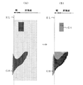
図6は図3に対応した読取り画像の要部を示す図、図7は手指像の検出対象範囲を示す図である。
【0025】
図6(A)において、読取り画像Gは、予備スキャンニング時の撮影情報であって、ブック原稿BDの上面像G1、原稿台20の撮影像G20、及び手指像GHから構成されている。上面像G1の左端EL及び右端ERは、ブック原稿BDにおける見開き方向の端面(裾)の下端に対応し、上述したとおり原稿台20とブック原稿BDとの輝度の差異に基づいて検出される。上面像G1には、原稿面S1の左右両端に印刷されたインデックスT(図3参照)の像Gtが含まれている。図6(B)のように、左手の手指像GHは、原稿面S1の下地部分より暗い低輝度部h1と、照明光の正反射などのために下地部分と同程度の明るさとなった高輝度部h2,h3とからなる。高輝度部h2,h3の存在によって、低輝度部h1は、左端ELの付近で図の上半部が欠け、且つ指の先端に対応する部分が欠けた形状となっている。一方、上面像G1には、高輝度部h3に隣接して他より明るい高輝度部g1が存在する。この高輝度部g1は、光源からの直接の照明光と指で反射した間接の照明光とで照らされた下地部分の撮影像である。
【0026】
本実施形態では、読取り画像Gに対して、図7のように左端EL及び右端ERのそれぞれを外端とする2つの検出対象領域A80が設定される。つまり、上面像G1の左端部及び右端部に範囲を限定して手指像の検出が行われる。検出対象領域A80の左右方向の幅は、従来に生じていた検出漏れを防ぐために、標準的な書籍の余白より十分に大きい値、例えば左右の各ページの1/3〜1/2程度に設定される。
【0027】
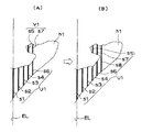
図8は読取り画像の修正の概要を説明するための図である。図8(A)中の点線は検出対象ラインの位置を示し、太い実線は検出された線分を示している。
例えば、左側の手指像GHの検出に際しては、左端ELの位置のライン(開始ライン)から順に、検出対象領域A80の各ライン又は一定数置きのラインに注目し、設定数(例えば4)以上の低輝度の画素が連なった線分を検出する。2番目以降のラインにおいては、検出した各線分について、1つ前のラインの線分とのライン方向の位置関係を調べる。ライン方向の位置が一定値以上の長さにわたって重複する場合には、それらの線分を同一の画像に対応する画像要素とみなし、これらの線分(連結線分群)で特定される画像領域を記憶する。このとき、メモリ容量を削減するため、画像領域のライン方向の全ての画素位置におけるライン配列方向の内端の画素位置のみを記憶する。手指像GHやインデックス像Gtが存在する場合には、注目ラインが内側(基準位置Psに近い側)へ移動するにつれて画像領域が拡がる。そして、最終のラインにおける処理が終了した時点で記憶されている画像領域の内端の画素位置〔図8(B)における太い実線〕より外側の範囲の画像データを白地データに置き換える。これにより、手指像GHはその形状に係わらず消去される。なお、左端ELと接する画像のみが消去されるので、左端ELから離れたインデックス像Gtは消去されずに残る。また、裾に縞状の暗部が存在したために線分検出においてインデックス像Gtが左端ELと接したとしても、後述する上下端の位置変化の判別によって、インデックス像Gtの誤消去が防止される。
【0028】
図9は線分の連結の一例を示す図である。
手指像GHの低輝度部h1の形状によっては、あるラインにおいて手指像GHに対応する複数の線分が検出される場合がある。
【0029】
図9(A)の段階では5番目のラインまで線分の検出が進み、計7本の線分s1〜s7が検出されている。線分s1は開始ラインに存在し、これを含めた計5本の線分s1〜s4,s6は、左端ELと接する主画像領域(手指領域)に対応する第1の連結線分群U1に属している。一方、残りの線分s5,s7は、左端ELから離れた画像領域(独立領域)に対応する第2の連結線分群V1に属している。
【0030】
図9(B)の段階では6番目のラインまで検出が進み、新たに線分s8が検出されている。この線分s8は、5番目のラインの一方の線分s6と重複し、且つ他方の線分s7とも重複する。このことから、線分s8が第1の連結線分群U1に加えられるとともに、第2の連結線分群V1が第1の連結線分群U1に統合され、全ての線分s1〜s8が手指領域の構成要素となる。なお、不定数の独立領域の記憶、及び手指領域への統合に係るデータ処理の便宜を図る上で、各領域の内端位置リストをチェーン形式でメモリに格納するのが有効である。
【0031】
図10は2値化の閾値の補正方法を説明するための図である。
線分の検出に係る2値化、すなわち注目画素が低輝度であるか否かの判断に際して、基本的には全てのラインについて、該当する側の検出対象領域A80の輝度ヒストグラムに基づく閾値を共通に用いる。具体的には、0〜255の輝度範囲のうち、最も度数の大きいピーク輝度Bpに対して、例えば次の関係をもつ輝度Bsを基準に2値化をする。
【0032】
Bs=0.55×Bp+70
検出対象領域A80の輝度ヒストグラムに基づくことにより、上面像G1の全体の輝度ヒストグラムに基づく閾値を用いたり、ライン毎にそのラインの輝度ヒストグラムに基づく閾値を用いたりするよりも、良好の結果の得られることが実験によって確かめられた。ただし、手指像GHにおける指の先端に対応した部位に高輝度部h3が存在すると、その高輝度部h3が消去されないおそれがある。
【0033】
そこで、局所的に閾値を高めに設定し、高輝度部h3が低輝度部として検出されるようにする。すなわち、図10のように、注目ラインLの注目画素Qを左下隅とする所定サイズのウインドウ(画素マトリクス)Wを設定し、ウインドウWの中に一定値(例えば232)以上の輝度の画素がある場合には、注目画素の位置を指の先端に対応すると判断し、注目画素に対する閾値を一定値(例えば216)に設定する。こうような局所的な閾値の補正は、特に読取り画像Gとして赤外光画像を用いる場合に有用である。
【0034】
図11はインデックス像の消去を防止する手法を説明するための図である。ここでのインデックスは、黒ベタの長方形の中に白抜き文字が存在する標準的な形態のものである。
【0035】
図11(A)のようにインデックス像Gtの端縁を構成する画素列には、微視的には若干の位置ずれがある。本実施形態では、ずれ量が一定画素分(例えば2画素分)以下であれば、端縁を直線とみなす。
【0036】
誤消去を防止するため、上述のように各ラインに注目して検出した線分の上端及び下端の画素位置を記憶しておき、連続基準長としての所定ライン数(例えば10)以上にわたってライン方向の位置が一定である画素列を検出する。これら画素列の中に注目ラインの線分の上下端と重なる一対の画素列があれば、それらの一方をインデックス像Gtの上辺とし、他方を下辺とする。そして、上辺と下辺とで囲まれた領域を、白抜けの有無に係わらずインデックス像Gtと認識して消去対象から除外する。
【0037】
図11(B)の段階では、画素列a及び画素列bが連続基準長未満であるので、画素列aと画素列bとで挟まれた領域をインデックス像Gtとは認識しない。
図11(C)の段階では、画素列a及び画素列bが連続基準長に達した。しかし、白抜けのために画素列aは連続基準長未満の画素列cと対をなし、画素列bも連続基準長未満の画素列dと対をなしており、画素列a,bが注目ラインの1本の線分の上下端と重ならないので、画素列aと画素列bとで挟まれた領域をインデックス像Gtとは認識しない。図11(D)の段階では、画素列a,bが連続基準長以上であり、注目ラインの1本の線分の上下端と重なるので、画素列aと画素列bとで挟まれた領域をインデックス像Gtと認識し、記憶データを削除して消去対象から除外する。以降の段階では、画素列aと画素列bとで挟まれた領域が削除されているので、インデックス像Gtの線分は手指領域に連結されない。
【0038】
以下、フローチャートに基づいてブックスキャナ1の動作を説明する。
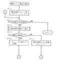
図12はブックスキャナ1の概略の動作を示すフローチャートである。
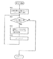
スタートキー52,53のオンに呼応して照明ランプを点灯し、予備スキャンニングを行う(#1)。読取り画像を画像メモリ103から読み出して、高さ測定(#2)、原稿サイズ検出(#3)、検出対象領域A80の設定(#4)、左手指像の検出(#5)、及び右手指像の検出(#6)を順に実行する。左手指像の検出及び右手指像の検出の順序を入れ換えても何ら問題はない。所定の動作設定を行った後、フォーカシングを行いながら原稿画像を撮影する本スキャンニングを実行する(#7)。本スキャンニングで得られた読取り画像に対して、手指像の消去(#8)、その他の画像処理(#9)を行い、シート原稿の場合と同様の見栄えの良い読取り情報を外部装置へ出力する(#10)。
【0039】
なお、左手指像の検出及び右手指像の検出の処理内容は、左右の位置関係が異なることを除いて同様である。したがって、以下では、左手指像の検出のみについて説明する。
【0040】
図13は左手指像の検出サブルーチンのフローチャートである。
左側の検出対象領域A80の画像データを値別にカウントして輝度ヒストグラムを作成する(#21)。ピーク輝度Bpを検出し(#22)、全てのラインにおける2値化に共通に用いる閾値(広域閾値)Bsを算出する(#23)。
【0041】
次に、開始ラインとして、原稿サイズ検出で得られた左端ELに対応するラインを設定する(#24)。ここで、読取り画像GにXY座標系を当てはめ(図6参照)、左右方向(ライン配列方向)の画素位置をxで、上下方向(ライン方向)の画素位置をyで表現するものとする。線分検出の処理時間を短縮する上で、開始ラインを指の先端にできるだけ近づけるのが望ましい。また、裾は枠消しと呼称されるマスキングで消去されるので、手指像として検出されても何ら問題はない。
【0042】
続いて、開始ラインの線分の検出を行う(#25)。このルーチンでは、検出された全ての線分を無条件で左端ELと接する主画像領域として登録する。以下、登録されている主画像領域を手指領域という。
【0043】
線分が検出されない場合は、手指像GHが無いのでメインルーチンへリターンする(#26)。線分があれば、注目ラインを内側へ移し、インデックスの認識と保存、消去もれ対策のための独立領域処理を行いながら、重複条件を満たす線分を手指領域に連結していく(#28、#29)。また、ライン毎に線分が連結しなかった(孤立していると判明した) 独立領域を消去する(#30、#31)。
【0044】
図14及び図15は開始ラインの線分の検出サブルーチンのフローチャートである。
上方から画素毎に2値化を行いながら線分を検出する。線分毎に長さを判定して設定値(例えば4画素分)以上のものを全て線分として登録する。この動作
を検出対象領域A80の上端から下端まで行う(#51〜64)。
【0045】
図16は図14の検出位置の画素の2値化サブルーチンのフローチャートである。
検出位置の画素(注目画素)Qに対してウインドウW(下地検出範囲) を設定する(#531)。ウインドウW内に下地が高輝度になっている画素があれば、注目画素Qが指の先端の上部側にあると判断して閾値を広域閾値より大きい補正値である局所閾値とする(#532、#533)。ウインドウW内に高輝度の画素がなければ、閾値を広域閾値とする(#534)。そして、設定した広域閾値又は局所閾値によって画像データを2値化する(#535〜#537)。
【0046】
図17は図15の線分の連結サブルーチンのフローチャートである。
ステップ#641〜#644において、手指領域の内端位置を記憶する。手指領域は変数を検出領域の上下方向の画素数個並べた配列で、検出された手指領域のもっとも内側のx座標をデータとしてもつ。線分を連結するときは、上端と下端の範囲と並列に線分のx座標(注目ライン位置でもある) を格納する。
【0047】
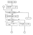
図18〜図20は図13の線分の検出と連結サブルーチンのフローチャートである。
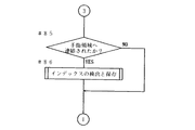
2番目以降のラインの線分検出処理(#71〜#83)は、図14の開始ラインの処理(#51〜#73)と同様である。所定長の線分を検出すれば、既存の画像領域(手指領域又は独立領域)への連結の処理が行われ(#84)、インデックス像Gtの検出と保存の処理が行われる(#85、#86)。
【0048】
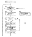
図21及び図22は図19の既存領域への連結サブルーチンのフローチャートである。
ステップ#841〜#856の処理内容は次のとおりである。まず、独立領域の中で線分が連結するのものをリストアップし、これらの1 つを選択してこれにリストアップしたもの全ての独立領域データを統合し、残った独立領域のデータを消去する。統合とは、各領域の領域データを重ね合わせることである。線分が手指領域への重なり条件を満たすときは、統合された独立領域データをさらに手指領域に統合してこの独立領域データを消去する。独立領域にも手指領域にも線分が連結しないときは、新しい独立領域を作成する。手指領域にのみに連結するときは、手指領域に連結するだけで独立領域に関する処理は行わない。
【0049】
図23は図21の連結済み手指領域との重なりのカウントサブルーチンのフローチャートである。
このルーチンのステップ#4471〜#4479において、線分の手指領域との重なり部分の中で最長部分の重なり長を得る。なお、図21の独立領域との重なりのカウントも図23と同様の処理(手指領域が独立領域になるだけの違い)である。
【0050】
図24は図20のインデックスの検出と保存サブルーチンのフローチャート、図25及び図26は図24の上辺の検出サブルーチンのフローチャートである。
まず、上辺の検出(#910)を行う。このステップ#910の処理は、ノイズ・原稿の傾き・回転走査による場合の樽型歪みなどを考慮して、上辺の連続性に許容幅をもたせるために行われ、その詳細は図25及び図26のとおりである(#9101〜9113)。許容幅は2画素分とされている。上辺の長さが連続基準長の10画素分以上であれば(#911)、下辺についても上辺と同様に連続性に許容幅をもたせるための処理を行う(#912)。
【0051】
以上の実施形態によれば、検出対象領域A80内で共通の閾値による2値化を行うので、インデックスや罫線の辺縁がなめらかになり、認識処理が容易である。検出された手指像から外側の領域を全て消去するので、実際の手指像GHに含まれる高輝度部h2,h3も消去できる。検出された手指領域の内端の位置のみをデータとして記憶するのでメモリの小容量化が図れる。検出対象領域A80が十分に広いので、通常の余白よりも内側に入り込んでいても手指像GHを検出できる。手指像GHと文字などの必要画像が重なっていてもよい。ライン単位で線分の検出と連結の判定であり、また、一方向の連結の判定であるので、データ処理が速くスキャンニングと並行して処理することも可能である。白抜きのあるインデックスTを簡単な処理で認識できる。インデックスTの検出に原稿のセッティングの傾きに対する許容性を備えることができる。
【0052】
【発明の効果】
請求項1乃至請求項5の発明によれば、ユーザーの手指の像を確実に消去して読取り品質を高めることができる。
【0053】
請求項2の発明によれば、インデックスに代表される端縁近傍の必要な画像の消去を防止することができる。
請求項3の発明によれば、手指の像の検出精度を高めることができる。
【0054】
請求項4の発明によれば、データ処理の高速化及び負担の軽減を図ることができる。
【図面の簡単な説明】
【図1】本発明に係るブックスキャナの外観を示す斜視図である。
【図2】ブックスキャナによる読取りの模式図である。
【図3】原稿を押さえた状態を示す図である。
【図4】ブックスキャナの要部の機能ブロック図である。
【図5】原稿面の高さ分布の測定方法を説明するための図である。
【図6】図3に対応した読取り画像の要部を示す図である。
【図7】手指像の検出対象範囲を示す図である。
【図8】読取り画像の修正の概要を説明するための図である。
【図9】線分の連結の一例を示す図である。
【図10】2値化の閾値の補正方法を説明するための図である。
【図11】インデックス像の消去を防止する手法を説明するための図である。
【図12】ブックスキャナの概略の動作を示すフローチャートである。
【図13】左手指像の検出サブルーチンのフローチャートである。
【図14】開始ラインの線分の検出サブルーチンのフローチャートである。
【図15】開始ラインの線分の検出サブルーチンのフローチャートである。
【図16】図14の検出位置の画素の2値化サブルーチンのフローチャートである。
【図17】図15の線分の連結サブルーチンのフローチャートである。
【図18】図13の線分の検出と連結サブルーチンのフローチャートである。
【図19】図13の線分の検出と連結サブルーチンのフローチャートである。
【図20】図13の線分の検出と連結サブルーチンのフローチャートである。
【図21】図19の線分の既存領域への連結サブルーチンのフローチャートである。
【図22】図19の線分の既存領域への連結サブルーチンのフローチャートである。
【図23】図21の連結済み手指領域との重なりのカウントサブルーチンのフローチャートである。
【図24】図20のインデックスの検出と保存サブルーチンのフローチャートである。
【図25】図24の上辺の検出サブルーチンのフローチャートである。
【図26】図24の上辺の検出サブルーチンのフローチャートである。
【図27】従来の問題点を示す図である。
【符号の説明】
1 ブックスキャナ(画像読取り装置)
20 原稿台
30 撮像ユニット(撮影手段)
101 CPU
114 端縁検出部
115 線分検出部
116 連結判定部(連結線分群を抽出する手段)
143 マスキング部(画像を消去する手段)
A80 検出対象領域(複数のラインを包含する領域)
BD ブック原稿(原稿)
EL 左端(原稿の端縁)
ER 右端(原稿の端縁)
s1〜s8 線分
U1 連結線分群
V1 連結線分群(両端位置が一定である線分群)[0001]
BACKGROUND OF THE INVENTION
The present invention relates to a method for correcting a read image for an image reading apparatus suitable for reading a bound original such as a book or a magazine.
[0002]
[Prior art]
An image reading device called a book scanner has been commercialized. In this apparatus, an imaging system is disposed above the document table, and an open space having a height of several tens of cm exists between the document table and the imaging system. When reading a bound document such as a book or magazine (referred to as a “book document”), the user opens the book document on the document table and sets it upward. In response to the start key being turned on, the book scanner turns on the illumination lamp, starts scanning the document surface (spreading surface), and sequentially outputs the read images to the external device. If the external device is a printer, a copy image is formed in real time. According to the book scanner, it is possible to turn the page while it is placed on the document table, so that it is possible to increase the efficiency of reading a large number of pages.
[0003]
Unlike a sheet document, a book document often requires that the edge of the spread surface be held down in order to maintain the spread state. In this case, the user's finger and back of the hand are photographed together with the document. In order to improve the appearance of the output image of the book scanner, it is necessary to erase the image of a finger or hand (hereinafter referred to as “hand image”).
Conventionally, extraction of a finger image from a read image has been performed by discrimination of density or color. That is, a method of extracting a pixel image of pixels having a certain density or more by examining the pixel density in the peripheral area (margin area) of the document (Japanese Patent Laid-Open No. 6-78133), and performing color photography to obtain the skin color from the photographed image. There is a technique (Japanese Patent Laid-Open No. 6-105091) for extracting the image of the above. The accuracy of extraction can be increased by checking whether or not the document extends over both sides of the document edge and determining the size.
[0004]
[Problems to be solved by the invention]
Conventionally, when there is an inclined part on the surface of the user's finger that the illumination light is regularly reflected and enters the photographing system, the inclined part is a highlight with a brightness close to the background of the document (the color is There is a problem that the shape of the finger cannot be correctly detected by either the density or the color. Further, in the color discrimination, it is difficult to set the skin color range, and there is a possibility that a detection error may occur due to nail polish.
In the technique of extracting a finger image by density discrimination, it is necessary to limit the detection target area A8 of the finger image to the margin around the
[0005]
It is an object of the present invention to reliably erase an image of a user's finger and improve reading quality. Another object is to prevent erasure of necessary images in the vicinity of an edge represented by an index.
[0006]
[Means for Solving the Problems]
Check the pixel value of the captured image for the area where the hand image may exist, that is, the edge of the document, and extract the area consisting of adjacent low-brightness pixels and touching the edge of the document as a finger image To do. When only the extracted hand image is erased, for example, when the center portion of the actual hand image has high brightness due to regular reflection of illumination light, the center portion with high brightness remains without being erased. Therefore, the extracted hand image and the image outside it are erased. Note that it is possible to perform reading twice, extract a finger image in the first reading and set an erasing range, and erase an image corresponding to the erasing range set before in the second reading. It is also possible to extract and erase the hand image in one reading.
[0007]
The values of all the pixels in the target area or pixels belonging to every predetermined number of lines (one-direction pixel columns) are examined for each line. The presence / absence of adjacency in the line arrangement direction is determined by the degree of overlap of pixel positions in the line direction. As a criterion for determining whether or not a pixel has low luminance, a threshold value calculated from a luminance histogram of the entire target region is commonly used for all lines. Thereby, compared with the case where the threshold value calculated from the luminance histogram of each line is individually applied for each line, the contour of the extracted finger image becomes smooth and the shape can be easily recognized.
[0008]
The method of the invention of
A set of line segments whose positions in the line direction overlap with the line segments of adjacent lines over a length equal to or greater than the number of set pixels, Equivalent to Extracting a connected line segment group including line segments composed of pixels of the line of the position, out of the read image, pixels corresponding to the inner end of the line arrangement direction at each pixel position in the line direction in the connected line segment group, and these Outside the pixel And the pixel positions in the line direction are the same Consisting of pixels image Is to erase.
[0009]
The method of the invention of
[0010]
According to a third aspect of the invention, the set value is calculated based on a luminance histogram of a region including the plurality of lines in the read image.
According to the method of the invention of
[0011]
The apparatus of the invention of
[0012]
DETAILED DESCRIPTION OF THE INVENTION
FIG. 1 is a perspective view showing an external appearance of a
[0013]
The
[0014]
An operation panel OP is provided on the front surface of the
[0015]
The
[0016]
When using the
[0017]
The
[0018]
FIG. 4 is a functional block diagram of the main part of the
The
[0019]
The photoelectric conversion signal output from the
[0020]
In the main scanning, focusing is performed in accordance with the progress in the sub-scanning direction, and image data captured in a focused state is input to the image processing circuit 104 via the image memory 103. The image processing circuit 104 erases an unnecessary image including a finger image and a luminance conversion unit 141 that optimizes the output luminance according to the background luminance, a distortion correction unit 142 that changes the image according to the height distribution of the document surface, and the like. A masking unit 143 for performing data processing of contents set by the CPU 101 is performed. Erasing unnecessary images is a process of replacing pixel values with white background density values. Image data that has passed through the image processing circuit 104 is output to the external device. Examples of the external device include a printer, a display, an image memory device, and an image editing device (computer system).
[0021]
FIG. 5 is a diagram for explaining a method of measuring the height distribution of the document surface. The broken line in the figure indicates the position of the noticed line. Here, it is assumed that the user has taken a picture without pressing the document.
[0022]
The read image G0 includes a photographic image (upper surface image) G1 on the upper surface of the book original BD, a photographic image G20 on the original table 20, and a photographic image G18 on the
[0023]
Since the document table 20 is dark, the photographed image G20 is darker than other images.
Further, since the end surface S3 is illuminated together with the document surface S1, the end surface image G181 is brighter than the background image G180. Therefore, it is possible to extract the upper surface image G1 and the end surface image G181 by determining the magnitude of the brightness, and to measure the height distribution of the document surface S1 and the document size. Specifically, the luminance (pixel value) is examined in order from the top pixel in the main scanning direction at every sampling position (line) at a predetermined interval, and the top pixel position (pixel number) in the range where the luminance exceeds the first threshold th1. ) N1, and detect pixel positions n3 and n4 on the leading and trailing ends in the range where the luminance exceeds the second threshold th2 (th2> th1). The number of pixels between the pixel position n1 and the known pixel position n2 corresponding to the leading edge of the
[0024]
Next, the procedure for detecting and erasing a finger image by connecting line segments, which is a feature of the present invention, will be described.
FIG. 6 is a diagram illustrating a main part of a read image corresponding to FIG. 3, and FIG. 7 is a diagram illustrating a detection target range of a finger image.
[0025]
In FIG. 6A, the read image G is photographing information at the time of preliminary scanning, and is composed of a top image G1 of the book document BD, a photographed image G20 of the document table 20, and a finger image GH. The left end EL and the right end ER of the top image G1 correspond to the lower end of the end face (hem) in the spread direction of the book document BD, and are detected based on the difference in luminance between the document table 20 and the book document BD as described above. The top image G1 includes images Tt of the index T (see FIG. 3) printed on both left and right sides of the document surface S1. As shown in FIG. 6B, the finger image GH of the left hand has a low brightness part h1 that is darker than the background part of the document surface S1, and a high brightness that is about the same as the background part due to regular reflection of illumination light. It consists of luminance parts h2 and h3. Due to the presence of the high luminance portions h2 and h3, the low luminance portion h1 has a shape in which the upper half of the figure is missing near the left end EL and the portion corresponding to the tip of the finger is missing. On the other hand, in the top image G1, there is a high luminance part g1 that is brighter than the others adjacent to the high luminance part h3. The high luminance portion g1 is a photographed image of the ground portion illuminated by direct illumination light from the light source and indirect illumination light reflected by the finger.
[0026]
In the present embodiment, two detection target areas A80 having the left end EL and the right end ER as outer ends are set for the read image G as shown in FIG. That is, the finger image is detected by limiting the range to the left end portion and the right end portion of the top image G1. The width in the left-right direction of the detection target area A80 is set to a value sufficiently larger than the margin of a standard book, for example, about 1/3 to 1/2 of the left and right pages, in order to prevent detection omissions that have occurred in the past. Is done.
[0027]
FIG. 8 is a diagram for explaining an outline of correction of a read image. The dotted line in FIG. 8A indicates the position of the detection target line, and the thick solid line indicates the detected line segment.
For example, when detecting the left hand finger image GH, pay attention to each line of the detection target region A80 or every other number in order from the line (start line) at the position of the left end EL, and the set number (for example, 4) or more. A line segment in which low luminance pixels are connected is detected. In the second and subsequent lines, the positional relationship in the line direction with the line segment of the previous line is examined for each detected line segment. When the position in the line direction overlaps over a length of a certain value or more, these line segments are regarded as image elements corresponding to the same image, and the image area specified by these line segments (connected line segment group) is determined. Remember. At this time, in order to reduce the memory capacity, only the pixel positions at the inner end in the line arrangement direction in all the pixel positions in the line direction of the image area are stored. When the finger image GH or the index image Gt exists, the image area expands as the target line moves inward (side closer to the reference position Ps). Then, the image data in the range outside the pixel position [thick solid line in FIG. 8B) of the inner end of the image area stored at the time when the processing in the final line is completed is replaced with white background data. Thereby, the finger image GH is erased regardless of its shape. Since only the image in contact with the left end EL is erased, the index image Gt away from the left end EL remains without being erased. Further, even if the index image Gt is in contact with the left end EL in the line segment detection due to the presence of a striped dark portion at the bottom, erroneous erasure of the index image Gt is prevented by determining the position change of the upper and lower ends, which will be described later.
[0028]
FIG. 9 is a diagram illustrating an example of connection of line segments.
Depending on the shape of the low brightness portion h1 of the finger image GH, a plurality of line segments corresponding to the finger image GH may be detected in a certain line.
[0029]
In the stage of FIG. 9A, the detection of the line segment proceeds to the fifth line, and a total of seven line segments s1 to s7 are detected. The line segment s1 exists in the start line, and a total of five line segments s1 to s4 and s6 including this belong to the first connected line segment group U1 corresponding to the main image area (finger area) in contact with the left end EL. ing. On the other hand, the remaining line segments s5 and s7 belong to the second connected line segment group V1 corresponding to the image area (independent area) separated from the left end EL.
[0030]
In the stage of FIG. 9B, detection proceeds to the sixth line, and a line segment s8 is newly detected. This line segment s8 overlaps with one line segment s6 of the fifth line and also overlaps with the other line segment s7. From this, the line segment s8 is added to the first connecting line segment group U1, the second connecting line segment group V1 is integrated into the first connecting line segment group U1, and all the line segments s1 to s8 are in the finger region. It becomes a component. In order to facilitate the storage of an indefinite number of independent areas and the data processing related to integration into the finger area, it is effective to store the inner end position list of each area in the memory in a chain format.
[0031]
FIG. 10 is a diagram for explaining a binarization threshold value correction method.
When binarization related to line segment detection, that is, whether or not the target pixel has low luminance, basically, a common threshold is used for all lines based on the luminance histogram of the corresponding detection target area A80. Used for. Specifically, binarization is performed on the peak luminance Bp having the highest frequency in the luminance range of 0 to 255 with reference to the luminance Bs having the following relationship, for example.
[0032]
Bs = 0.55 × Bp + 70
Based on the luminance histogram of the detection target region A80, better results can be obtained than using a threshold value based on the entire luminance histogram of the top image G1 or using a threshold value based on the luminance histogram of the line for each line. It was confirmed by experiment. However, if the high luminance part h3 exists in a part corresponding to the tip of the finger in the hand image GH, the high luminance part h3 may not be erased.
[0033]
Therefore, the threshold value is locally set to be high so that the high luminance part h3 is detected as the low luminance part. That is, as shown in FIG. 10, a window (pixel matrix) W having a predetermined size with the target pixel Q of the target line L as the lower left corner is set, and pixels having a luminance of a certain value (for example, 232) or more are set in the window W. In some cases, it is determined that the position of the target pixel corresponds to the tip of the finger, and the threshold for the target pixel is set to a constant value (for example, 216). Such local threshold correction is particularly useful when an infrared image is used as the read image G.
[0034]
FIG. 11 is a diagram for explaining a technique for preventing deletion of an index image. The index here has a standard form in which white characters are present in a solid black rectangle.
[0035]
As shown in FIG. 11A, there is a slight positional shift microscopically in the pixel column that forms the edge of the index image Gt. In the present embodiment, the edge is regarded as a straight line if the shift amount is equal to or less than a certain pixel (for example, two pixels).
[0036]
In order to prevent erroneous erasure, the pixel positions of the upper and lower ends of the line segment detected by paying attention to each line as described above are stored, and the line direction is extended over a predetermined number of lines (for example, 10) as the continuous reference length. A pixel row having a constant position is detected. If there is a pair of pixel columns that overlap the upper and lower ends of the line segment of the target line in these pixel columns, one of them is the upper side of the index image Gt and the other is the lower side. Then, an area surrounded by the upper side and the lower side is recognized as an index image Gt regardless of the presence or absence of white spots, and is excluded from the erasure target.
[0037]
In the stage of FIG. 11B, since the pixel column a and the pixel column b are less than the continuous reference length, the region sandwiched between the pixel column a and the pixel column b is not recognized as the index image Gt.
In the stage of FIG. 11C, the pixel column a and the pixel column b have reached the continuous reference length. However, because of white spots, the pixel column a is paired with the pixel column c less than the continuous reference length, and the pixel column b is also paired with the pixel column d less than the continuous reference length. Since the upper and lower ends of one line segment of the line do not overlap, the area sandwiched between the pixel column a and the pixel column b is not recognized as the index image Gt. In the stage of FIG. 11D, since the pixel columns a and b are longer than the continuous reference length and overlap with the upper and lower ends of one line segment of the target line, the region sandwiched between the pixel column a and the pixel column b Is recognized as an index image Gt, and the stored data is deleted and excluded from the erasure target. In the subsequent stage, since the region sandwiched between the pixel column a and the pixel column b is deleted, the line segment of the index image Gt is not connected to the finger region.
[0038]
The operation of the
FIG. 12 is a flowchart showing a schematic operation of the
In response to the
[0039]
The processing contents of the left hand finger image detection and the right hand finger image detection are the same except that the left and right positional relationships are different. Accordingly, only the detection of the left hand finger image will be described below.
[0040]
FIG. 13 is a flowchart of the left hand image detection subroutine.
A luminance histogram is created by counting the image data of the left detection target area A80 by value (# 21). The peak luminance Bp is detected (# 22), and a threshold value (wide area threshold value) Bs commonly used for binarization in all lines is calculated (# 23).
[0041]
Next, a line corresponding to the left end EL obtained by the document size detection is set as a start line (# 24). Here, an XY coordinate system is applied to the read image G (see FIG. 6), and a pixel position in the left-right direction (line arrangement direction) is represented by x and a pixel position in the vertical direction (line direction) is represented by y. In order to shorten the processing time for line segment detection, it is desirable to make the start line as close as possible to the tip of the finger. Further, since the skirt is erased by masking called frame erasing, there is no problem even if it is detected as a finger image.
[0042]
Subsequently, the line segment of the start line is detected (# 25). In this routine, all detected line segments are unconditionally registered as the main image area in contact with the left end EL. Hereinafter, the registered main image area is referred to as a finger area.
[0043]
If no line segment is detected, there is no finger image GH, and the process returns to the main routine (# 26). If there is a line segment, the line of interest is moved inward, and the segment satisfying the overlapping condition is connected to the finger area while performing independent area processing for recognizing, storing, and erasing the index (# 28). # 29). In addition, the independent areas in which the line segments are not connected for each line (identified as isolated) are deleted (# 30, # 31).
[0044]
14 and 15 are flowcharts of the start line segment detection subroutine.
A line segment is detected while performing binarization for each pixel from above. The length is determined for each line segment, and everything over a set value (for example, 4 pixels) is registered as a line segment. This behavior
Is performed from the upper end to the lower end of the detection target area A80 (# 51 to 64).
[0045]
FIG. 16 is a flowchart of the binarization subroutine for the pixel at the detection position in FIG.
A window W (background detection range) is set for the pixel (target pixel) Q at the detection position (# 531). If there is a pixel whose background is high in the window W, it is determined that the target pixel Q is on the upper side of the tip of the finger, and the threshold value is set as a local threshold value that is a correction value larger than the wide area threshold value (# 532). , # 533). If there is no high-luminance pixel in the window W, the threshold is set to the wide area threshold (# 534). Then, the image data is binarized by the set wide area threshold or local threshold (# 535 to # 537).
[0046]
FIG. 17 is a flowchart of the connecting subroutine of the line segments in FIG.
In steps # 641 to # 644, the inner edge position of the finger region is stored. The finger region is an array in which several pixels are arranged in the vertical direction of the detection region, and has the innermost x coordinate of the detected finger region as data. When connecting line segments, the x coordinate (also the line position of interest) of the line segment is stored in parallel with the range of the upper and lower ends.
[0047]
18 to 20 are flowcharts of the line segment detection and connection subroutine of FIG.
The line segment detection process (# 71 to # 83) for the second and subsequent lines is the same as the start line process (# 51 to # 73) in FIG. If a line segment of a predetermined length is detected, a connection process to an existing image area (a finger area or an independent area) is performed (# 84), and an index image Gt is detected and stored (# 85, # 86).
[0048]
21 and 22 are flowcharts of the subroutine for linking to the existing area in FIG.
The processing contents of steps # 841 to # 856 are as follows. First, list the independent regions that are connected by line segments, select one of them, consolidate all the independent region data listed, and erase the remaining independent region data To do. Integration refers to superimposing region data of each region. When the line segment satisfies the overlapping condition with the finger region, the integrated independent region data is further integrated into the finger region and the independent region data is deleted. If no line segment is connected to either the independent area or the finger area, a new independent area is created. When connecting only to the finger area, the process relating to the independent area is not performed, but only to the finger area.
[0049]
FIG. 23 is a flowchart of the counting subroutine for overlapping with the connected finger area of FIG.
In steps # 44771 to # 4479 of this routine, the overlapping length of the longest portion among the overlapping portions with the finger region of the line segment is obtained. Note that the overlap count with the independent area in FIG. 21 is the same processing as in FIG. 23 (difference that the finger area becomes an independent area).
[0050]
24 is a flowchart of the index detection and storage subroutine of FIG. 20, and FIGS. 25 and 26 are flowcharts of the upper side detection subroutine of FIG.
First, the upper side is detected (# 910). The processing of
[0051]
According to the above embodiment, since binarization is performed using a common threshold within the detection target area A80, the edges of the index and ruled line are smooth, and the recognition process is easy. Since all the outer regions are erased from the detected finger image, the high luminance portions h2 and h3 included in the actual finger image GH can also be erased. Since only the position of the detected inner edge of the finger area is stored as data, the capacity of the memory can be reduced. Since the detection target area A80 is sufficiently wide, the finger image GH can be detected even if it enters the inside of the normal margin. The finger image GH and a necessary image such as a character may overlap. Since line segment detection and connection determination are performed on a line-by-line basis and connection determination in one direction is performed, data processing can be performed quickly and in parallel with scanning. A white index T can be recognized by a simple process. The detection of the index T can be provided with tolerance for the inclination of the document setting.
[0052]
【The invention's effect】
According to the first to fifth aspects of the present invention, it is possible to reliably erase the image of the user's finger and improve the reading quality.
[0053]
According to the second aspect of the present invention, it is possible to prevent a necessary image from being erased near the edge represented by the index.
According to invention of
[0054]
According to the invention of
[Brief description of the drawings]
FIG. 1 is a perspective view showing an external appearance of a book scanner according to the present invention.
FIG. 2 is a schematic diagram of reading by a book scanner.
FIG. 3 is a diagram illustrating a state in which a document is pressed.
FIG. 4 is a functional block diagram of a main part of the book scanner.
FIG. 5 is a diagram for explaining a method for measuring the height distribution of a document surface.
6 is a diagram showing a main part of a read image corresponding to FIG. 3. FIG.
FIG. 7 is a diagram illustrating a detection target range of a finger image.
FIG. 8 is a diagram for explaining an outline of correction of a read image.
FIG. 9 is a diagram illustrating an example of connection of line segments.
FIG. 10 is a diagram for explaining a binarization threshold value correction method;
FIG. 11 is a diagram for explaining a technique for preventing erasure of an index image.
FIG. 12 is a flowchart showing a schematic operation of the book scanner.
FIG. 13 is a flowchart of a left hand image detection subroutine.
FIG. 14 is a flowchart of a start line segment detection subroutine;
FIG. 15 is a flowchart of a start line segment detection subroutine;
FIG. 16 is a flowchart of a binarization subroutine for pixels at the detection position in FIG. 14;
FIG. 17 is a flowchart of a connection subroutine of the line segments in FIG.
18 is a flowchart of the line segment detection and connection subroutine of FIG.
FIG. 19 is a flowchart of the line segment detection and connection subroutine of FIG. 13;
20 is a flowchart of the line segment detection and connection subroutine of FIG. 13;
FIG. 21 is a flowchart of a subroutine for connecting to the existing area of the line segment in FIG. 19;
22 is a flowchart of a subroutine for connecting to the existing area of the line segment in FIG. 19;
FIG. 23 is a flowchart of a counting subroutine for overlapping with the connected finger area of FIG. 21;
24 is a flowchart of the index detection and storage subroutine of FIG. 20;
FIG. 25 is a flowchart of an upper side detection subroutine of FIG. 24;
FIG. 26 is a flowchart of an upper side detection subroutine of FIG. 24;
FIG. 27 is a diagram showing a conventional problem.
[Explanation of symbols]
1 Book scanner (image reader)
20 Document table
30 Imaging unit (imaging means)
101 CPU
114 Edge detection unit
115 Line segment detector
116 Connection determination unit (means for extracting a connection line segment group)
143 Masking part (means for erasing images)
A80 detection target area (area including multiple lines)
BD book manuscript (original)
EL Left edge (edge of document)
ER right edge (the edge of the document)
s1-s8 line segment
U1 connecting line segment
V1 connected line segment group (line segment group where both end positions are constant)
Claims (5)
前記撮影手段によって得られた読取り画像における原稿の端縁に相当する位置のラインを含む複数のラインを対象として、前記各ライン毎に設定値より低輝度の画素が連なった線分を検出し、
隣接するラインの線分と互いにライン方向の位置が設定画素数分以上の長さにわたって重複する前記線分の集合であって、前記端縁に相当する位置のラインの画素からなる線分を含む連結線分群を抽出し、
前記読取り画像のうち、前記連結線分群におけるライン方向の各画素位置でのライン配列方向の内端に該当する画素と、これら画素より外側でかつライン方向の画素位置が同一である画素とからなる像を消去する
ことを特徴とする読取り画像の修正方法。A method for correcting a read image in an upward-setting type image reading apparatus in which a photographing unit for photographing a document is arranged above a document table,
For a plurality of lines including a line at a position corresponding to an edge of a document in a read image obtained by the photographing unit, a line segment in which pixels having lower luminance than a set value are connected for each line is detected.
A set of line segments whose adjacent line segments overlap with each other in the line direction over a length equal to or greater than the set number of pixels, and include line segments composed of pixels in the line corresponding to the edge. Extract connected line segments,
Of the read image, the pixel corresponding to the inner end in the line arrangement direction at each pixel position in the line direction in the connecting line segment group, and a pixel outside the pixels and having the same pixel position in the line direction. A method for correcting a read image, wherein the image is erased.
請求項1記載の読取り画像の修正方法。The method for correcting a read image according to claim 1, wherein a group of line segments that are composed of the line segments adjacent to each other in a line arrangement direction and whose both end positions in the line direction are substantially constant over a set number of lines is excluded from the connection line segment group. .
請求項1又は請求項2記載の読取り画像の修正方法。The method for correcting a read image according to claim 1, wherein the set value is calculated based on a luminance histogram of a region including the plurality of lines in the read image.
前記読取り画像のうち、最終のラインにおける前記処理が終了した時点の前記内端に該当する画素と、これら画素より外側でかつライン方向の画素位置が同一である画素とからなる像を消去する
請求項1乃至請求項3のいずれかに記載の読取り画像の修正方法。For each of the plurality of lines, the line segments are sequentially detected from the edge side, the line segments are detected to extract the connected line segment group, and the line arrangement direction at each pixel position in the line direction of the extracted connected line segment group Repeat the process of storing the pixel position of the inner edge of
An image composed of a pixel corresponding to the inner end at the time when the processing in the last line is completed and an image having a pixel position outside the pixels and having the same pixel position in the line direction is erased from the read image. The method for correcting a read image according to any one of claims 1 to 3.
前記撮影手段の撮像面上での原稿の端縁を検出する手段と、
前記撮影手段によって得られた読取り画像における前記端縁に相当する位置のラインを含む複数のラインを対象として、前記各ライン毎に設定値より低輝度の画素が連なった線分を検出する手段と、
隣接するラインの線分と互いにライン方向の位置が設定画素数分以上の長さにわたって重複する前記線分の集合であって、前記端縁に相当する位置のラインの画素からなる線分を含む連結線分群を抽出する手段と、
前記読取り画像のうち、前記連結線分群におけるライン方向の各画素位置でのライン配列方向の内端に該当する画素と、これら画素より外側でかつライン方向の画素位置が同一である画素とからなる像を消去する手段とを有した
ことを特徴とする画像読取り装置。An image reading device of an upward setting type in which a photographing means for photographing a document is arranged above a document table,
Means for detecting an edge of the document on the imaging surface of the photographing means;
Means for detecting a line segment in which pixels each having a lower luminance than a set value are connected for each line for a plurality of lines including a line at a position corresponding to the edge in the read image obtained by the photographing means; ,
A set of line segments whose adjacent line segments overlap with each other in the line direction over a length equal to or greater than the set number of pixels, and include line segments composed of pixels in the line corresponding to the edge. Means for extracting connected line segments;
Of the read image, the pixel corresponding to the inner end in the line arrangement direction at each pixel position in the line direction in the connecting line segment group, and a pixel outside the pixels and having the same pixel position in the line direction. And an image erasing device.
Priority Applications (1)
| Application Number | Priority Date | Filing Date | Title |
|---|---|---|---|
| JP14134497A JP3707204B2 (en) | 1997-05-30 | 1997-05-30 | Method for correcting read image and image reading apparatus |
Applications Claiming Priority (1)
| Application Number | Priority Date | Filing Date | Title |
|---|---|---|---|
| JP14134497A JP3707204B2 (en) | 1997-05-30 | 1997-05-30 | Method for correcting read image and image reading apparatus |
Publications (2)
| Publication Number | Publication Date |
|---|---|
| JPH10336422A JPH10336422A (en) | 1998-12-18 |
| JP3707204B2 true JP3707204B2 (en) | 2005-10-19 |
Family
ID=15289786
Family Applications (1)
| Application Number | Title | Priority Date | Filing Date |
|---|---|---|---|
| JP14134497A Expired - Fee Related JP3707204B2 (en) | 1997-05-30 | 1997-05-30 | Method for correcting read image and image reading apparatus |
Country Status (1)
| Country | Link |
|---|---|
| JP (1) | JP3707204B2 (en) |
Families Citing this family (1)
| Publication number | Priority date | Publication date | Assignee | Title |
|---|---|---|---|---|
| EP3343338A4 (en) | 2015-08-24 | 2019-05-01 | Sony Corporation | Information processing device, information processing method, and program |
-
1997
- 1997-05-30 JP JP14134497A patent/JP3707204B2/en not_active Expired - Fee Related
Also Published As
| Publication number | Publication date |
|---|---|
| JPH10336422A (en) | 1998-12-18 |
Similar Documents
| Publication | Publication Date | Title |
|---|---|---|
| JP3436025B2 (en) | Correction method of read image and image reading device | |
| JPH10336439A (en) | Image reader | |
| JP4037512B2 (en) | Image reading device | |
| JPH08154154A (en) | Image reader | |
| US5969795A (en) | Image reading apparatus | |
| JPH10190972A (en) | Image reader | |
| JP3973462B2 (en) | Image capture method | |
| US5987163A (en) | Apparatus and method for determining the size of a page size in an image reader | |
| JP2007067966A (en) | Image processing system | |
| JP3707204B2 (en) | Method for correcting read image and image reading apparatus | |
| US20100165417A1 (en) | Image processing method, image processing apparatus, and computer-readable storage medium | |
| US8422785B2 (en) | Image processing apparatus, image processing method, and program | |
| US20150319336A1 (en) | Peripheral with image processing function | |
| US7679792B2 (en) | Merged camera and scanner | |
| JPH10255024A (en) | Picture reader | |
| US20120013953A1 (en) | Image processing method, program, and image processing apparatus | |
| JPH10262147A (en) | Image reading device | |
| JP3384208B2 (en) | Image reading device | |
| JPH10136194A (en) | Image reader | |
| JP6859779B2 (en) | Image reader, image reading method and image reading program | |
| JPH08237485A (en) | Image reader | |
| JP2001069332A (en) | Picture reader | |
| JP3852247B2 (en) | Image forming apparatus and transfer image distortion correction method | |
| JPH10200724A (en) | Picture reader | |
| JP5540587B2 (en) | Bar code analyzing apparatus and program |
Legal Events
| Date | Code | Title | Description |
|---|---|---|---|
| A977 | Report on retrieval |
Free format text: JAPANESE INTERMEDIATE CODE: A971007 Effective date: 20040705 |
|
| A131 | Notification of reasons for refusal |
Free format text: JAPANESE INTERMEDIATE CODE: A131 Effective date: 20040713 |
|
| A711 | Notification of change in applicant |
Free format text: JAPANESE INTERMEDIATE CODE: A712 Effective date: 20040903 |
|
| RD03 | Notification of appointment of power of attorney |
Free format text: JAPANESE INTERMEDIATE CODE: A7423 Effective date: 20040907 |
|
| A521 | Written amendment |
Free format text: JAPANESE INTERMEDIATE CODE: A523 Effective date: 20040909 |
|
| A131 | Notification of reasons for refusal |
Free format text: JAPANESE INTERMEDIATE CODE: A131 Effective date: 20050426 |
|
| A521 | Written amendment |
Free format text: JAPANESE INTERMEDIATE CODE: A523 Effective date: 20050620 |
|
| TRDD | Decision of grant or rejection written | ||
| A01 | Written decision to grant a patent or to grant a registration (utility model) |
Free format text: JAPANESE INTERMEDIATE CODE: A01 Effective date: 20050712 |
|
| A61 | First payment of annual fees (during grant procedure) |
Free format text: JAPANESE INTERMEDIATE CODE: A61 Effective date: 20050725 |
|
| R150 | Certificate of patent or registration of utility model |
Free format text: JAPANESE INTERMEDIATE CODE: R150 |
|
| FPAY | Renewal fee payment (event date is renewal date of database) |
Free format text: PAYMENT UNTIL: 20080812 Year of fee payment: 3 |
|
| FPAY | Renewal fee payment (event date is renewal date of database) |
Free format text: PAYMENT UNTIL: 20090812 Year of fee payment: 4 |
|
| FPAY | Renewal fee payment (event date is renewal date of database) |
Free format text: PAYMENT UNTIL: 20090812 Year of fee payment: 4 |
|
| FPAY | Renewal fee payment (event date is renewal date of database) |
Free format text: PAYMENT UNTIL: 20100812 Year of fee payment: 5 |
|
| FPAY | Renewal fee payment (event date is renewal date of database) |
Free format text: PAYMENT UNTIL: 20100812 Year of fee payment: 5 |
|
| FPAY | Renewal fee payment (event date is renewal date of database) |
Free format text: PAYMENT UNTIL: 20110812 Year of fee payment: 6 |
|
| FPAY | Renewal fee payment (event date is renewal date of database) |
Free format text: PAYMENT UNTIL: 20120812 Year of fee payment: 7 |
|
| FPAY | Renewal fee payment (event date is renewal date of database) |
Free format text: PAYMENT UNTIL: 20130812 Year of fee payment: 8 |
|
| LAPS | Cancellation because of no payment of annual fees |
