JP3703718B2 - Clot filter - Google Patents
Clot filter Download PDFInfo
- Publication number
- JP3703718B2 JP3703718B2 JP2000571984A JP2000571984A JP3703718B2 JP 3703718 B2 JP3703718 B2 JP 3703718B2 JP 2000571984 A JP2000571984 A JP 2000571984A JP 2000571984 A JP2000571984 A JP 2000571984A JP 3703718 B2 JP3703718 B2 JP 3703718B2
- Authority
- JP
- Japan
- Prior art keywords
- filter
- longitudinal axis
- hook
- leg
- legs
- Prior art date
- Legal status (The legal status is an assumption and is not a legal conclusion. Google has not performed a legal analysis and makes no representation as to the accuracy of the status listed.)
- Expired - Fee Related
Links
Images


Classifications
-
- A—HUMAN NECESSITIES
- A61—MEDICAL OR VETERINARY SCIENCE; HYGIENE
- A61F—FILTERS IMPLANTABLE INTO BLOOD VESSELS; PROSTHESES; DEVICES PROVIDING PATENCY TO, OR PREVENTING COLLAPSING OF, TUBULAR STRUCTURES OF THE BODY, e.g. STENTS; ORTHOPAEDIC, NURSING OR CONTRACEPTIVE DEVICES; FOMENTATION; TREATMENT OR PROTECTION OF EYES OR EARS; BANDAGES, DRESSINGS OR ABSORBENT PADS; FIRST-AID KITS
- A61F2/00—Filters implantable into blood vessels; Prostheses, i.e. artificial substitutes or replacements for parts of the body; Appliances for connecting them with the body; Devices providing patency to, or preventing collapsing of, tubular structures of the body, e.g. stents
- A61F2/01—Filters implantable into blood vessels
- A61F2/0105—Open ended, i.e. legs gathered only at one side
-
- A—HUMAN NECESSITIES
- A61—MEDICAL OR VETERINARY SCIENCE; HYGIENE
- A61F—FILTERS IMPLANTABLE INTO BLOOD VESSELS; PROSTHESES; DEVICES PROVIDING PATENCY TO, OR PREVENTING COLLAPSING OF, TUBULAR STRUCTURES OF THE BODY, e.g. STENTS; ORTHOPAEDIC, NURSING OR CONTRACEPTIVE DEVICES; FOMENTATION; TREATMENT OR PROTECTION OF EYES OR EARS; BANDAGES, DRESSINGS OR ABSORBENT PADS; FIRST-AID KITS
- A61F2/00—Filters implantable into blood vessels; Prostheses, i.e. artificial substitutes or replacements for parts of the body; Appliances for connecting them with the body; Devices providing patency to, or preventing collapsing of, tubular structures of the body, e.g. stents
- A61F2/01—Filters implantable into blood vessels
- A61F2/0103—With centering means
-
- A—HUMAN NECESSITIES
- A61—MEDICAL OR VETERINARY SCIENCE; HYGIENE
- A61F—FILTERS IMPLANTABLE INTO BLOOD VESSELS; PROSTHESES; DEVICES PROVIDING PATENCY TO, OR PREVENTING COLLAPSING OF, TUBULAR STRUCTURES OF THE BODY, e.g. STENTS; ORTHOPAEDIC, NURSING OR CONTRACEPTIVE DEVICES; FOMENTATION; TREATMENT OR PROTECTION OF EYES OR EARS; BANDAGES, DRESSINGS OR ABSORBENT PADS; FIRST-AID KITS
- A61F2/00—Filters implantable into blood vessels; Prostheses, i.e. artificial substitutes or replacements for parts of the body; Appliances for connecting them with the body; Devices providing patency to, or preventing collapsing of, tubular structures of the body, e.g. stents
- A61F2/01—Filters implantable into blood vessels
- A61F2/012—Multiple filtering units
-
- A—HUMAN NECESSITIES
- A61—MEDICAL OR VETERINARY SCIENCE; HYGIENE
- A61F—FILTERS IMPLANTABLE INTO BLOOD VESSELS; PROSTHESES; DEVICES PROVIDING PATENCY TO, OR PREVENTING COLLAPSING OF, TUBULAR STRUCTURES OF THE BODY, e.g. STENTS; ORTHOPAEDIC, NURSING OR CONTRACEPTIVE DEVICES; FOMENTATION; TREATMENT OR PROTECTION OF EYES OR EARS; BANDAGES, DRESSINGS OR ABSORBENT PADS; FIRST-AID KITS
- A61F2/00—Filters implantable into blood vessels; Prostheses, i.e. artificial substitutes or replacements for parts of the body; Appliances for connecting them with the body; Devices providing patency to, or preventing collapsing of, tubular structures of the body, e.g. stents
- A61F2/01—Filters implantable into blood vessels
- A61F2002/016—Filters implantable into blood vessels made from wire-like elements
-
- A—HUMAN NECESSITIES
- A61—MEDICAL OR VETERINARY SCIENCE; HYGIENE
- A61F—FILTERS IMPLANTABLE INTO BLOOD VESSELS; PROSTHESES; DEVICES PROVIDING PATENCY TO, OR PREVENTING COLLAPSING OF, TUBULAR STRUCTURES OF THE BODY, e.g. STENTS; ORTHOPAEDIC, NURSING OR CONTRACEPTIVE DEVICES; FOMENTATION; TREATMENT OR PROTECTION OF EYES OR EARS; BANDAGES, DRESSINGS OR ABSORBENT PADS; FIRST-AID KITS
- A61F2/00—Filters implantable into blood vessels; Prostheses, i.e. artificial substitutes or replacements for parts of the body; Appliances for connecting them with the body; Devices providing patency to, or preventing collapsing of, tubular structures of the body, e.g. stents
- A61F2/82—Devices providing patency to, or preventing collapsing of, tubular structures of the body, e.g. stents
- A61F2/848—Devices providing patency to, or preventing collapsing of, tubular structures of the body, e.g. stents having means for fixation to the vessel wall, e.g. barbs
- A61F2002/8483—Barbs
-
- A—HUMAN NECESSITIES
- A61—MEDICAL OR VETERINARY SCIENCE; HYGIENE
- A61F—FILTERS IMPLANTABLE INTO BLOOD VESSELS; PROSTHESES; DEVICES PROVIDING PATENCY TO, OR PREVENTING COLLAPSING OF, TUBULAR STRUCTURES OF THE BODY, e.g. STENTS; ORTHOPAEDIC, NURSING OR CONTRACEPTIVE DEVICES; FOMENTATION; TREATMENT OR PROTECTION OF EYES OR EARS; BANDAGES, DRESSINGS OR ABSORBENT PADS; FIRST-AID KITS
- A61F2230/00—Geometry of prostheses classified in groups A61F2/00 - A61F2/26 or A61F2/82 or A61F9/00 or A61F11/00 or subgroups thereof
- A61F2230/0002—Two-dimensional shapes, e.g. cross-sections
- A61F2230/0028—Shapes in the form of latin or greek characters
- A61F2230/005—Rosette-shaped, e.g. star-shaped
-
- A—HUMAN NECESSITIES
- A61—MEDICAL OR VETERINARY SCIENCE; HYGIENE
- A61F—FILTERS IMPLANTABLE INTO BLOOD VESSELS; PROSTHESES; DEVICES PROVIDING PATENCY TO, OR PREVENTING COLLAPSING OF, TUBULAR STRUCTURES OF THE BODY, e.g. STENTS; ORTHOPAEDIC, NURSING OR CONTRACEPTIVE DEVICES; FOMENTATION; TREATMENT OR PROTECTION OF EYES OR EARS; BANDAGES, DRESSINGS OR ABSORBENT PADS; FIRST-AID KITS
- A61F2230/00—Geometry of prostheses classified in groups A61F2/00 - A61F2/26 or A61F2/82 or A61F9/00 or A61F11/00 or subgroups thereof
- A61F2230/0063—Three-dimensional shapes
- A61F2230/0067—Three-dimensional shapes conical
Abstract
Description
【0001】
近年、血管通路内への導入を容易にするために小さく圧縮することができ、導入後は通路の壁に接触するよう展開することのできる医療用具が多数考案されている。これらの用具の一つとして、静脈内で展開し、静脈内壁と係合することにより一所に維持される血餅フィルタが挙げられる。このような用具は、第1の比較的撓みやすい低温状態と、第2の比較的堅い高温状態とを有する形状記憶材料で作ると、利点が大きいことがわかった。これらの用具を感温材料で作ると、所定の転移温度を下回る温度下に置かれ、撓みやすい、緊張の少ない状態にあるときには、用具を圧縮し、デリバリーカテーテルの内径に嵌合させることができるが、転移温度以上になると用具が展開し、比較的堅くなる。
【0002】
すでに知られている自己展開型医療用具は、用具に熱記憶性を与える、チタンとニッケルの合金であるニチノール製である。この合金に固有の特徴は、熱感応による形状記憶を有する点であり、このため、この合金で作られた用具は、温度変態レベルより低い温度まで冷却されるとマルテンサイト状態となり、これにより軟化して、比較的圧縮された細長い状態でカテーテルに入れることができ、また、温度変態レベルより高い、人間の体温程度の選択された温度まで昇温されると、記憶されている形状に戻ることが可能である。わずかな温度変化で交換可能な微晶質構造が2つあることから、2つの交換可能な形状が可能である。合金の組成を変えることで、用具が第1の形状にあるとされる温度を広い範囲で変えることができる。即ち、人体に使用するときには、合金の転移温度範囲を98.6°F付近に集中させてもよいが、体温の異なる他の動物に使用する際には合金を容易に変更することができる。
【0003】
Simonの米国特許第4,425,908号は、熱形状記憶材料で作られた非常に効果的な血餅フィルタを開示している。すでに開発されている多くの大静脈フィルタと同様に、このフィルタは永久フィルタであり、一度植込みを行うと、その場所に留まるようになっている。このようなフィルタは、フィルタを大静脈内の一所に固定するための構造を含んでいる。固定するための構造としては、例えば端部がフック状であり、この端部が血管壁に入ることでフィルタが血管の長さ方向のいずれの方向へも移動しないようにする、分岐脚などがある。このタイプのフィルタのフックは堅い、曲がらないものであり、このタイプのフィルタを植え込んでから2週間から6週間経過すると、内皮層が分岐脚を覆うように成長し、フックをその場所に固定する。いかなる方法でフィルタを取り除こうとしても、大静脈を傷つけたり、破断する危険が伴う。
【0004】
多くの医療処置上、患者が短期間にわたり肺動脈塞栓症のリスクを負うことがあるが、この肺動脈塞栓症はフィルタを植え込むことで緩和できる。この場合、肺動脈塞栓が数週間又は数ヶ月で消滅することもあることから、患者は永久的な植込みを拒むことが多い。しかしながら、現在使用されているフィルタのほとんどは、ある場所に2週間以上留まった後では、容易に或いは安全に取り除くことができない。従って、除去する際に血管壁を損傷する危険性のない、長期間用の一時的フィルタはまだ開発されていないのである。
【0005】
除去可能なフィルタを開発する試みの一つとして、中央軸に沿って円錐形の2つのフィルタバスケットを形成した。各バスケットは、バスケットの中央ハブから外方向に放射状に広がる、離間された支柱からなっている。中央ハブは圧縮ユニットによって離間して保持され、2つのバスケットが互いに向かい合うよう、それぞれのアームは重なり合っている。このタイプのデバイスでは、バスケットを相互に離れる方向に引っ張り、又圧縮ユニットを破砕するために、フィルタの各端部に挿入される2つの除去用デバイスを使用しなければならない。アームの端部は、血管壁と略平行関係とされており、先端は血管壁を突き通すことのないよう、内側に曲げられている。このタイプのデバイスを、内皮層がアームを覆うように成長する前に引き抜くならば、血管壁の損傷は最小限ですむ。しかしながら、内皮層が成長した後では、フィルタ部を互いに引き離すときに内側や長手方向に動かすことで、この内皮層が断裂する可能性がある。Irieの米国特許第5,370,657号に、このような2つの除去デバイスを必要とするタイプの従来技術の除去可能フィルタの一例が示されている。
【0006】
本発明の主たる目的は、温度感応によるオーステナイト状態とマルテンサイト状態とを有する形状記憶材料で作られ、植込み後長期間が経過した後でも、1つの除去デバイスを用いて血管壁を損傷することなく容易に除去することのできる、血管植込み型フィルタを提供することにある。
【0007】
本発明の別の目的は、温度感応によるオーステナイト状態において、フィルタを一所に維持するため、対向する脚により血管壁に力を印加するよう動作し、フィルタの脚が内皮層により覆われた後で血管壁を損傷することなく容易に除去することのできる、ニチロール製の血餅フィルタを提供することにある。
【0008】
本発明の更に別の目的は、中央軸に対して同じ方向に傾斜した1組のアームと、1組の脚とを有する、斬新な、改良されたフィルタを提供することにある。1組のアームの端部は、フィルタを血管の中央部に配置するために、血管壁と係合する方向に向けられており、1組の脚の端部は、フィルタが血管に沿って長さ方向に移動することを防ぐために、血管壁と係合する方向に向けられている。脚の端部は、血管壁を損傷することなく内皮層から引き抜くことができるよう、脚よりも撓みやすくするためフック状になっている。
【0009】
本発明によると、弾性のある、長手方向に延長可能な血餅フィルタは、静脈に挿入するために、長手軸に向けて半径方向内側へ折り畳むことにより折り畳まれた形状をとることができ、また、静脈内では半径方向へ自己展開し、長手方向に離間された2ヶ所において静脈の内壁と接触するようになっている。フィルタには前縁部及び後縁部があり、複数のワイヤを含んでいる。フィルタが通常の展開形状にあるとき、ワイヤは複数の長尺のアーム及び脚の形態をとり、ワイヤ間の隙間はフィルタの前端においてフィルタバスケットの開口部を形成している。ワイヤは、長手方向に離間された周縁位置の二ヶ所において静脈の内壁と接触するための周縁部を有する。アームはフィルタを中央に寄せるよう動作する。また、脚の端部はフィルタを固定するためにフック状とされているが、フィルタの除去を容易にするため、力が加わるとこれに応じて直線状になる。
【0010】
通常の展開形状から長手軸に向かって半径方向内側に折り畳むことができ、静脈に挿入するための折り畳まれた形状をとることのできるフィルタを提供するために、第1の低温状態と、第2の高温状態とを有する熱形状記憶材料でできた複数のワイヤ部で血餅フィルタを形成することが好ましい。材料は、低温状態にあるとき(ワイヤ部を直線状にすることができるよう)比較的撓みやすく、高温状態にあるときには弾性的に変形可能であり、比較的堅い、所定の機能的形状をとる。
【0011】
材料が高温状態にあるとき、フィルタは同軸の第1及び第2のフィルタバスケットを含む。各フィルタバスケットはフィルタの長手軸について略対称であり、両方のフィルタバスケットはフィルタ前端に対して凹形となっている。
【0012】
血餅フィルタ本体を、ニチノールワイヤなどのニチノール合金材料で作ることにより、材料のマルテンサイト状態とオーステナイト状態の転換は、人の体温程度かそれを下回る転移温度又は転移温度範囲よりも高くなり、或いは低くなることによる温度の変化により達成される得る。カテーテルへの挿入を容易にするためにニチノールフィルタ本体を軟化及び収縮させ、また挿入後に血管やその他の通路内で本体を展開させ硬化させるために、このような制御による温度転移はこれまでも利用されていた。本発明のフィルタはニチノールのような感温形状記憶材料で作られることが好ましいが、ステンレス鋼などの圧縮可能なばね金属や適切なプラスチック製とすることもできる。
【0013】
ここで図1を参照すると、複数組の金属ワイヤで作られた血餅フィルタ10が展開状態で示されている。ワイヤの一端はハブ12で束ねられ、ハブにプラズマ溶接されるか接合されている。熱形状記憶材料で作られたワイヤが低温のマルテンサイト相にあるとき、複数組のワイヤを直線状とすることができ、内径が約2mm(8番のフレンチカテーテル)の細いプラスチック管を長さ方向に通過することのできる、直線状態に保たれる。高温のオーステナイト形態にあるとき、フィルタ10は、図1に示すような、前成形されたフィルタリング形状に戻る。同様に、ばね金属のワイヤもカテーテル又は管内では直線状に圧縮され、管が外されると散開し、図1に示すようなフィルタ形状をとる。
【0014】
通常の展開形状又は前成形されたフィルタリング形状にあるとき、フィルタ10は、フィルタ前端において前向きに配置された第1フィルタバスケットセクション14と、前向きに配置された第2フィルタバスケットセクション16とを有する、ダブルフィルタである。2つのフィルタバスケットセクションは、共に、長さ方向に離間された2ヶ所において静脈17の内壁と係合する周縁部を形成しており、ハブ12を貫通する長手軸について略対称形とされている。他方、前向きに配置された第2フィルタバスケットセクション16は主としてフィルタ中央寄せユニットであり、全ての側面が血管と接触していなくてもよい。
【0015】
第2フィルタバスケットセクション16は、ハブ12からフィルタ10の前端へ向けて角度を付けて外方向に、その後下方向に延出するアーム18を形成する短いワイヤからなっている。各アーム18は、ハブ12から肩22まで角度を付けて外方向に延出する第1アームセクション20と、肩からフィルタ前端まで角度を付けて延出する外側アームセクション24とを有する。外側アームセクション24は略直線で、最大限に展開されたときその端部は円上にあり、ハブ12を血管の中央に配置するためにわずかな角度(好適には、10ないし45度の範囲)をなして血管壁と係合している。ハブ12をつかんで取り除くフィルタでは、ハブが中央にあることが重要である。通常、ハブ12から半径方向外側に延出する長さの等しい6本のワイヤ18が、円周方向に例えば弧の長さで60度相互に離間されている。
【0016】
第1フィルタバスケットセクション14は主たるフィルタであり、ふつう、円周方向に離間された6本の直線ワイヤ26を含む。ワイヤ26は、ハブ12から、フィルタ10の長手軸の外側へ傾いて下方向に延出する脚を形成する。ワイヤ26の長さは全て等しくすることもできるが、ふつうはワイヤ端部のフック28が相互に接触することなくカテーテル内に嵌合するよう、長さを変えている。ワイヤ26はワイヤ18よりもずっと長いことが好ましく、ワイヤ26の先端部は独特の形状に成形された外向きのフック28となっており、ワイヤ26が最大限に展開されたときフック28は円上にある。図1に示す展開状態において、ワイヤ26は血管壁17に対しわずかに角度をなしており(この角度は好適には10ないし45度である)、フック28は血管壁に入ってフィルタを動かないよう固定している。ワイヤ26はワイヤ18に対して半径方向に偏っており、隣り合うワイヤ18の中間に位置してもよく、また図9に示すように円周方向に弧の長さで60度離間されていてもよい。従って、フィルタバスケットセクション14と16を組み合わせることで、フィルタセクションが最大限に展開されたときに弧の長さで30度毎にワイヤが配置されていることになる。図1において血流方向を参照すると、フィルタセクション14はフィルタ10の前端部に向けて開いた凹形のフィルタバスケットを形成している。一方、フィルタセクション16は、フィルタセクション14の下流で、フィルタ10の前端部に向けて開いた凹形のフィルタバスケットを形成している。
【0017】
フック28の構造は重要である。すでに知られている永久大静脈フィルタの脚に、フックを形成したので、フィルタを一所に固定し、血管の長さ方向のいずれの方向へも移動しないようにするためにフィルタ10が展開されたとき、フック28は血管壁に入る。しかしながら、これらのフックが植え込まれ、内皮に覆われたとき、大静脈を損傷又は破断することなく、フック及びフィルタを抜き取ることができる。
【0018】
図1及び図2を参照すると、各フック28はフックと、フックが取り付けられた脚26との間に接合部30を有する。この接合部の断面積は、脚26やフックの接合部以外の部分の断面積と比べて著しく小さくなっている。接合部の大きさは、脚26が展開されたとき、フック28が大静脈の壁を突き通すことができるだけの堅さを有するような大きさとなっている。しかしながら、フックを血管壁から引き抜く際に、フックの受ける引張り力が接合部30に撓みを生じ、これによりフックは脚26の軸と平行となる、図2に破線で示す位置へ移動する。フックがこのように直線状になることにより、血管壁を断裂させることなくフックを引き抜くことができる。
【0019】
図3を参照すると、フック28全体の断面積を、全長にわたって脚26の断面積よりも小さくすることができることがわかるであろう。このようにすることで、引っ張る力に応じてフックが全長にわたって直線状となる。フック構造にこのような弾性を与えることで、フックが引き抜かれる間に血管壁を破断することを防止できる。
【0020】
すでに述べたように、フィルタをステンレス鋼、チタン、エルジロイ等の延性金属合金で作ることもできるが、ニチノールで作ることが最も好ましい。ニチノールは低モジュラス材料であるので、デバイスの移動に抗するために十分な固定力を維持しながら、低接触力及び低圧力を有するように、デバイスのアーム及び脚を設計することが可能である。フック28を取り除くために必要な負荷は、移動に抗するのに必要な力に対して調整することができる。このことは、フックの断面積又は幾可学的形状を変えることにより、或いは材料を選択することにより、達成される。
【0021】
温度感知に加え、ニチロールは、温度感応によりオーステナイト状態にあるとき、材料温度が転移温度レベルを上回っているときに材料がオーステナイト状態からマルテンサイト状態へ相変態を行うことを可能とする大きさの応力も感知しやすい。フック28の断面積の一部又は全体を脚26の断面積よりも小さくすることによって、フックを血管壁から除去するための力が印加されるとき、応力が断面積の小さい部分に集中し、フックが弾性的になり、直線状になる。従って、フックは、ニチロール、ばね金属、プラスチックのいずれからできていても、特定の負荷が印加されるとより直線状になるよう湾曲し、また負荷がなくなると元の形状へばねの力で戻るようになっている。完全な閉塞状態で、血管中の血圧を50mmHgまで高めることが可能であるとき、フックを変形させるのに必要な負荷又は応力を、デバイスの各フックに印加される負荷と相関させることができる。この負荷は、28mmの血管において、50mmHgの血圧差用の6本脚のデバイスの各脚について約70gmsである。細胞は約80gmsの負荷で破断してしまうため、フックを直線状にするために必要な負荷は各脚当たり80gms未満でなくてはならない。フィルタにかかる総負荷は420gmsであることが望ましく、また、各脚にかかる負荷を低減するため、フック28を付けた脚26を更に追加することもできる。フィルタにかかる負荷は、血管の寸法が小さければそれに合わせて小さくする。ここでの目的は、50mmHgの最大圧力と呼応する大きさの所定の負荷下で、フックが固定機構として機能することにある。その負荷下で形状を維持するためには、フックは血管細胞に損傷をもたらす大きさの負荷よりも大きい負荷で変形を開始し、また血管細胞に損傷をもたらす大きさの負荷よりもやや小さい負荷では解放されなければならない。フックは、血管壁からデバイスを安全に除去できるよう、やや直線状となることができる。
【0022】
フィルタ10を二週間以上にわたって血管内の一所に配置すると、内皮層がフック28を覆うように成長する。しかしながら、これらのフックは、引っ張る力を受けると、血管に対してわずかに角度を付けられた略直線形のワイヤセクションとなるため、6つのピンポイントサイズの損傷を内皮表面に残すのみで、フィルタを取り外すことが可能である。その手順としては、カテーテル又は同様の管状ユニットをハブ12の上から挿入し、アーム18と係合させる。ハブ12は静止した状態で保持され、カテーテルは下方向に移動されてアーム18を下方向に押圧する。次いでカテーテルをアーム26に係合させて下方向へ押圧し、フック28を内皮層から引き抜く。その後ハブ12をカテーテル内へ引き込み、フィルタ10全体をカテーテルの中に畳み込む。フィルタが形状記憶材料で作られている場合には、フィルタの折り畳みを容易にするため、冷却液をカテーテル内に流し込んでもよい。
【0023】
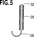
図4、図5、図6を参照すると、フィルタ10の脚は細い管になっており、その一端が開口してハブ12と通じている。脚の材料は管状のプラスチック、ばね金属、或いは熱形状記憶材料とすることができる。各フック28は長いシャフト32の端部に形成され、図4に破線で示されるように、管状脚26を通って延出し、ハブ12の中へ入る。フック28は、ハブ12の内部で引張り棒36の一端においてリング34に接続されている。フックとフック用シャフトはワイヤや熱形状記憶材料で作ることができ、フックの断面は、図4に示すシャフト32を引張り棒36を使って上方向に引いたときフックが直線状となり、図6に示すように管状脚26に入るような大きさである。従って、フィルタの除去手順は、フィルタが血管内の元の場所にある状態で、引張り棒をつかみ、フックを管状脚26の中に引き込む。次いで、除去用チューブをアーム20と26に被せるように動かし、フィルタを畳み込む。
【0024】
シャフト32を利用してフック28を管状脚26に引き込むために、ハブ12に近接する位置に多数のばねデバイスや同様の構造を備えてもよい。図7及び図8に示すように、複数の金属座金40を挿入することでハブ12をスリーブ38から離間させることもできる。スリーブ38は管状脚26の端部、及びアームがある場合にはアーム20の端部を受容し、固定する。
【0025】
従って、スリーブ38は一所に固定され、シャフト32は座金の中央部の開口を通って延出し、ハブ12に接続されている。座金40は熱形状記憶材料で作られ、その材料の温度変態レベルよりも低い温度では、図7に示すようにスリーブ38に対して平らである。しかしながら、座金40の温度が温度変態レベルを上回ると、図8に示すように、座金40はフィルタ10の長手軸に沿って上方向に湾曲し、ハブ12をスリーブ38から離間させる。この結果、ハブはシャフト32を上方向に引き上げ、フック28を管状脚26内に引き込むことになる。
【0026】
脚26、又は脚26とアーム20が熱形状記憶材料でできている場合、この材料の通常の温度変態レベルは、人の体温又は体温よりもわずかに低い、体温に近い温度である。この場合、座金40の温度変態レベルはアーム20や脚26のそれよりも高いので、フィルタが使用されているときには座金40は平らな状態にある。フィルタ10を取り除く際には、加温した食塩水または他の公知の手段を用いて、座金40をその温度変態レベルを上回る温度にまで加温する。
【0027】
管状脚を上記のように設計したので、フック28を直線状にし、引っ張るために支持血管の細胞に負荷を与える必要がない。ここでは、フックを直線状にするために必要な負荷は管状脚26によりもたらされる。
【0028】
図10を参照すると、管状脚26は各脚の外側端から離間された近接位置にある肩42から外方向に角度をなしている。脚がカテーテルや他のチューブ内に圧縮されている状態から身体の血管中に解放されると、このように脚が曲げてあるので、フックが実際上チューブ内でばね負荷を与えられ、チューブ内で展開したときに交差しないことが確実となる。脚は肩42から外方向に角度をつけられているため、フック28は挿入チューブがフィルタ10の後方へ引っ張られたとき、迅速に外方向へ展開する。
【図面の簡単な説明】
【図1】展開状態にある本発明の血餅フィルタの側面図である。
【図2】図1のフィルタの脚のフックの側面図である。
【図3】図1のフィルタの脚のフックの、第2実施形態の側面図である。
【図4】本発明の血餅フィルタの第2実施形態の側面図である。
【図5】図4のフィルタの脚の一部の断面図である。
【図6】フックを引いた状態の、図4のフィルタの脚の一部の断面図である。
【図7】図4の血餅フィルタのフック引張りユニットの側面図である。
【図8】フックを引いた状態の、図7のフック引張りユニットの側面図である。
【図9】血管内のある場所に配置された本発明の血餅フィルタの断面図である。
【図10】フック引張りユニットを有する、フィルタの第3実施形態の側面図である。[0001]
In recent years, many medical devices have been devised that can be compressed small to facilitate introduction into a vascular passage and that can be deployed to contact the wall of the passage after introduction. One of these devices is a clot filter that is deployed in a vein and maintained in place by engaging the inner wall of the vein. It has been found that such a device has significant advantages when made of a shape memory material having a first relatively flexible low temperature state and a second relatively hard high temperature state. When these devices are made of a temperature sensitive material, they can be compressed and fitted to the inner diameter of the delivery catheter when placed under a predetermined transition temperature and in a flexible, low tension state. However, when the temperature is higher than the transition temperature, the tool develops and becomes relatively stiff.
[0002]
Already known self-expanding medical devices are made of Nitinol, an alloy of titanium and nickel that imparts thermal memory to the device. A unique feature of this alloy is that it has a shape memory due to heat sensitivity, so that tools made of this alloy become martensitic when cooled to a temperature below the temperature transformation level, thereby softening. Can be placed into the catheter in a relatively compressed and elongated state, and will return to a memorized shape when heated to a selected temperature, such as the human body temperature, above the level of temperature transformation. Is possible. Since there are two microcrystalline structures that can be exchanged with small temperature changes, two exchangeable shapes are possible. By changing the composition of the alloy, the temperature at which the tool is assumed to be in the first shape can be varied over a wide range. That is, when used for the human body, the transition temperature range of the alloy may be concentrated in the vicinity of 98.6 ° F. However, the alloy can be easily changed when used for other animals having different body temperatures.
[0003]
Simon U.S. Pat. No. 4,425,908 discloses a highly effective clot filter made of a thermal shape memory material. Like many vena cava filters that have already been developed, this filter is a permanent filter that will remain in place once implanted. Such a filter includes a structure for securing the filter in one place in the vena cava. As a structure for fixing, for example, an end portion is a hook shape, and a branch leg or the like that prevents the filter from moving in any direction along the length of the blood vessel when the end portion enters the blood vessel wall. is there. The hooks of this type of filter are stiff and unbent, and after 2 to 6 weeks of implantation of this type of filter, the endothelial layer grows to cover the bifurcated leg and secures the hook in place . Any attempt to remove the filter involves the risk of damaging or breaking the vena cava.
[0004]
For many medical procedures, patients may be at risk for pulmonary embolism for a short period of time, which can be mitigated by implanting a filter. In this case, patients often refuse permanent implantation because pulmonary artery emboli may disappear in weeks or months. However, most of the filters currently in use cannot be removed easily or safely after staying in a location for more than two weeks. Thus, long-term temporary filters have not yet been developed that do not risk damaging the vessel wall when removed.
[0005]
In one attempt to develop a removable filter, two conical filter baskets were formed along the central axis. Each basket consists of spaced struts that radiate outwardly from the central hub of the basket. The central hub is held apart by the compression unit and the arms overlap so that the two baskets face each other. In this type of device, two removal devices inserted at each end of the filter must be used to pull the basket away from each other and to break the compression unit. The end of the arm is substantially parallel to the blood vessel wall, and the tip is bent inward so as not to penetrate the blood vessel wall. If this type of device is withdrawn before the endothelial layer grows over the arm, damage to the vessel wall is minimal. However, after the endothelial layer has grown, there is a possibility that the endothelial layer may be ruptured by moving the filter portions inward or in the longitudinal direction when they are separated from each other. An example of a prior art removable filter of the type requiring two such removal devices is shown in US Pat. No. 5,370,657 to Irie.
[0006]
The main object of the present invention is made of a shape memory material having an austenite state and a martensite state due to temperature sensitivity, and without damaging the blood vessel wall using a single removal device even after a long period of time has elapsed after implantation. It is an object of the present invention to provide a blood vessel implantable filter that can be easily removed.
[0007]
Another object of the present invention is to operate a force applied to the vessel wall by the opposing legs to keep the filter in place in the temperature-sensitive austenitic state, after the filter legs are covered by the endothelial layer. It is an object of the present invention to provide a clot filter made of nitilol that can be easily removed without damaging the vessel wall.
[0008]
Yet another object of the present invention is to provide a novel and improved filter having a set of arms and a set of legs inclined in the same direction relative to the central axis. The ends of the set of arms are oriented in a direction that engages the vessel wall in order to place the filter in the middle of the vessel, and the ends of the set of legs are extended by the filter along the vessel. In order to prevent it from moving in the vertical direction, it is oriented in the direction of engagement with the vessel wall. The end of the leg is hooked to be more flexible than the leg so that it can be pulled out of the endothelial layer without damaging the vessel wall.
[0009]
According to the present invention, an elastic, longitudinally extendable clot filter can take a folded shape by folding radially inward toward the longitudinal axis for insertion into a vein, and In the vein, it self-expands in the radial direction and comes into contact with the inner wall of the vein at two points spaced apart in the longitudinal direction. The filter has a leading edge and a trailing edge and includes a plurality of wires. When the filter is in its normal deployed shape, the wire takes the form of a plurality of elongated arms and legs, and the gap between the wires forms the opening of the filter basket at the front end of the filter. The wire has a peripheral edge for contacting the inner wall of the vein at two longitudinally spaced peripheral positions. The arm operates to center the filter. Further, the end of the leg has a hook shape for fixing the filter. However, in order to facilitate the removal of the filter, when the force is applied, the leg end portion becomes linear.
[0010]
In order to provide a filter that can be folded radially inward from the normal deployed shape toward the longitudinal axis and that can take a folded shape for insertion into a vein, a first cold state and a second It is preferable to form a clot filter with a plurality of wire portions made of a thermal shape memory material having a high temperature state. The material is relatively flexible when in the low temperature state (so that the wire portion can be straight), elastically deformable when in the high temperature state, and is relatively stiff and takes a predetermined functional shape. .
[0011]
When the material is in a hot state, the filter includes coaxial first and second filter baskets. Each filter basket is generally symmetrical about the longitudinal axis of the filter, and both filter baskets are concave with respect to the filter front end.
[0012]
By making the clot filter body with a Nitinol alloy material such as Nitinol wire, the conversion of the material's martensite and austenite states will be above or below the human body temperature or below the transition temperature or transition temperature range, or It can be achieved by a change in temperature due to lowering. This controlled temperature transition has been used to soften and shrink the Nitinol filter body for easy insertion into the catheter and to deploy and harden the body in the blood vessels and other passages after insertion. It had been. The filter of the present invention is preferably made of a temperature sensitive shape memory material such as Nitinol, but can also be made of a compressible spring metal such as stainless steel or a suitable plastic.
[0013]
Referring now to FIG. 1, a
[0014]
When in the normal unfolded shape or the pre-shaped filtering shape, the
[0015]
The second
[0016]
The first
[0017]
The structure of the
[0018]
Referring to FIGS. 1 and 2, each
[0019]
Referring to FIG. 3, it can be seen that the cross-sectional area of the
[0020]
As already mentioned, the filter can be made of a ductile metal alloy such as stainless steel, titanium or Elgiloy, but is most preferably made of nitinol. Since Nitinol is a low modulus material, it is possible to design device arms and legs to have low contact force and low pressure while maintaining sufficient fixation force to resist device movement. . The load required to remove the
[0021]
In addition to temperature sensing, Nitilol is sized to allow the material to undergo a phase transformation from the austenite state to the martensite state when the material temperature is above the transition temperature level when in the austenite state due to temperature sensitivity. It is easy to detect stress. By making part or all of the cross-sectional area of the
[0022]
When the
[0023]
Referring to FIGS. 4, 5, and 6, the leg of the
[0024]
A number of spring devices or similar structures may be provided in close proximity to the
[0025]
Accordingly, the
[0026]
If the
[0027]
Since the tubular leg is designed as described above, it is not necessary to load the cells of the supporting blood vessel in order to make the
[0028]
Referring to FIG. 10,
[Brief description of the drawings]
FIG. 1 is a side view of a blood clot filter of the present invention in a deployed state.
2 is a side view of a leg hook of the filter of FIG. 1. FIG.
3 is a side view of a second embodiment of the hook of the leg of the filter of FIG. 1. FIG.
FIG. 4 is a side view of a second embodiment of the clot filter of the present invention.
5 is a cross-sectional view of a portion of the filter leg of FIG. 4;
6 is a cross-sectional view of a portion of the filter leg of FIG. 4 with a hook pulled. FIG.
7 is a side view of the hook tension unit of the clot filter of FIG. 4. FIG.
8 is a side view of the hook tensioning unit of FIG. 7 with the hook pulled. FIG.
FIG. 9 is a cross-sectional view of a clot filter of the present invention placed at a location within a blood vessel.
FIG. 10 is a side view of a third embodiment of a filter having a hook pull unit.
Claims (18)
第1端と第2端とを有する複数の長尺の離間された脚を含み、前記脚の第1端は前記長手軸に近接する位置に取り付けられ、前記複数の長尺の離間された脚は、前記長手軸から離れて外方向へ、前記フィルタの展開状態において前記長手軸から外方向へ離間された前記脚の第2端へ向けて延びるよう形成されていて、前記複数の長尺の離間された脚の1つ又はそれ以上が、前記フィルタの展開状態において血管の内壁に入って係合するための、第2端の一点で終結し外方向に湾曲したフックを備え、前記フックが、前記フックを血管の内壁から除去するために印加される力に応答して湾曲し、前記脚と平行の直線形状となることを可能とするため、前記フックの少なくとも一部の断面積が、前記脚の断面積に比べて小さくなるよう形成されていて、前記フックの長さ全体に沿った断面積が、脚の断面積と比べて小さくなっていて、前記長尺の脚の形状が管状であり、前記湾曲したフックが前記長尺の脚に入れ子式に受容される長尺のシャフトを有し、前記フックを前記長尺の脚に引き込んで直線状とするため、前記シャフトが前記長尺の脚に対して移動可能であり、前記フィルタに作動手段が取り付けられ、前記作動手段が、前記フックを前記長尺の脚に引き込むために前記シャフトを前記長尺の脚に対して動かすため、前記シャフトに接続されている、
血餅フィルタ。It has a longitudinal axis in the middle and can be folded into the longitudinal axis for insertion into a blood vessel, and can also take the folded shape by contacting it with the wall of the blood vessel. A blood clot filter having a front end and a rear end, which can take a deployment shape by deploying radially outward from
A plurality of elongated spaced legs having a first end and a second end, wherein the first ends of the legs are attached to a position proximate to the longitudinal axis, the plurality of elongated spaced legs; Is formed to extend outward from the longitudinal axis toward the second end of the leg that is spaced outward from the longitudinal axis in the deployed state of the filter. One or more of the spaced legs comprises a hook that terminates at a second end and curves outwardly for entering and engaging the inner wall of the blood vessel in the deployed state of the filter, the hook comprising: In order to be able to bend in response to the force applied to remove the hook from the inner wall of the blood vessel and to have a linear shape parallel to the leg, Formed to be smaller than the cross-sectional area of the leg. The cross-sectional area along the entire length of the hook is smaller than the cross-sectional area of the leg, the shape of the long leg is tubular, and the curved hook is formed on the long leg. It has a long shaft that is telescopically received, and the hook is drawn into the long leg so as to be linear, so that the shaft is movable with respect to the long leg, and the filter Actuating means are attached, and the actuating means is connected to the shaft for moving the shaft relative to the elongated leg to retract the hook into the elongated leg.
Clot filter.
第1端と第2端とを有する複数の長尺の離間された脚を含み、前記脚の第1端は前記長手軸に近接する位置に取り付けられ、前記複数の長尺の離間された脚は、前記長手軸から離れて外方向へ、前記フィルタの展開状態において前記長手軸から外方向へ離間された前記脚の第2端へ向けて延びるよう形成されていて、前記複数の長尺の離間された脚の1つ又はそれ以上が管状とされていて、前記1つ又はそれ以上の脚が、前記フィルタの展開状態において血管の内壁に入って係合するための、第2端の一点で終結し外方向に湾曲したフックを備え、前記湾曲したフックが前記長尺の脚に入れ子式に受容される長尺のシャフトを有し、前記血管の前記内壁から前記フックを取り出すときにかかる力に応答して前記フックが長尺の前記脚と平行となるように変形するため前記フックの長さ全体に沿った断面積が、長尺の前記脚の横断面の面積に比べて小さくなっていて、
第1端と第2端とを有する複数の離間された長尺のアームを含み、前記アームの第1端は前記長手軸に近接する位置に取り付けられ、前記フィルタの展開状態において、前記アームの各々が、長手軸から、前記アームの前記第1端と第2端の間に離間されて配置された肩へ向けて外方向に角度をなして延出し、次いで前記肩から前記アームの第2端へ角度をなして延出し、
前記長尺の脚が前記フィルタの前端に向けて延出して第1フィルタバスケットを形成し、前記長尺のアームの各々が前記フィルタの長手軸から外方向へ前記フィルタの前端へ向けて角度を付けられ、次いで前記肩から前記フィルタの前端へ向けて角度を付けられて第2フィルタバスケットを形成する、
血餅フィルタ。It has a longitudinal axis in the middle and can be folded into the longitudinal axis for insertion into a blood vessel, and can also take the folded shape by contacting it with the wall of the blood vessel. A blood clot filter having a front end and a rear end, which can take a deployment shape by deploying radially outward from
A plurality of elongated spaced legs having a first end and a second end, wherein the first ends of the legs are attached to a position proximate to the longitudinal axis, the plurality of elongated spaced legs; Is formed to extend outward from the longitudinal axis toward the second end of the leg that is spaced outward from the longitudinal axis in the deployed state of the filter. One point of the second end for one or more of the spaced apart legs to be tubular, the one or more legs entering and engaging the inner wall of the blood vessel in the deployed state of the filter And has a long shaft that is telescopically received in the long leg, and is taken when the hook is removed from the inner wall of the blood vessel. In response to force, the hook is parallel to the long leg. Cross-sectional area along the entire length of the hook to deform so that, though smaller than the area of the cross section of the leg of the long,
A plurality of spaced apart elongate arms having a first end and a second end, the first end of the arm being attached at a position proximate to the longitudinal axis, and in the deployed state of the filter, Each extends outwardly at an angle from a longitudinal axis toward a shoulder spaced apart between the first and second ends of the arm, and then from the shoulder a second of the arm. Extend at an angle to the edge,
The elongate legs extend toward the front end of the filter to form a first filter basket, and each elongate arm is angled outwardly from the longitudinal axis of the filter toward the front end of the filter. Applied and then angled from the shoulder toward the front end of the filter to form a second filter basket;
Clot filter.
第1端と第2端とを有する複数の長尺の離間された管状の脚を含み、前記脚の第1端は前記長手軸に近接する位置に取り付けられ、前記複数の長尺の離間された脚は、前記長手軸から離れて外方向へ、前記フィルタの展開状態において前記長手軸から外方向へ前記フィルタの先端に向けて角度をなして延びかつ長尺の離間された前記脚の前記第2端へと角度をなして延びるよう形成されていて、
第1端と第2端とを有する複数の離間された長尺のアームを含み、前記アームの第1端は前記長手軸に近接する位置に取り付けられ、前記フィルタの展開状態において、前記アームの各々が、長手軸から、前記アームの前記第1端と第2端の間に離間されて配置された肩へ向けて外方向に角度をなして延出し、次いで前記肩から前記アームの第2端へ角度をなして延出している、
血餅フィルタ。It has a longitudinal axis in the middle and can be folded into the longitudinal axis for insertion into a blood vessel, and can also take the folded shape by contacting it with the wall of the blood vessel. A blood clot filter having a front end and a rear end, which can take a deployment shape by deploying radially outward from
A plurality of elongated spaced-apart tubular legs having a first end and a second end, the first end of the leg being attached at a position proximate to the longitudinal axis and the plurality of elongated spaced apart legs; The legs extend outwardly away from the longitudinal axis and at an angle toward the tip of the filter outward from the longitudinal axis in the deployed state of the filter, and the legs of the elongated spaced legs Formed to extend at an angle to the second end,
A plurality of spaced apart elongate arms having a first end and a second end, the first end of the arm being attached at a position proximate to the longitudinal axis, and in the deployed state of the filter, Each extends outwardly at an angle from a longitudinal axis toward a shoulder spaced apart between the first and second ends of the arm, and then from the shoulder a second of the arm. Extending at an angle to the edge,
Clot filter.
Applications Claiming Priority (3)
| Application Number | Priority Date | Filing Date | Title |
|---|---|---|---|
| US09/160,384 US6007558A (en) | 1998-09-25 | 1998-09-25 | Removable embolus blood clot filter |
| US09/160,384 | 1998-09-25 | ||
| PCT/US1999/020883 WO2000018467A1 (en) | 1998-09-25 | 1999-09-23 | Removable embolus blood clot filter |
Publications (2)
| Publication Number | Publication Date |
|---|---|
| JP2002525183A JP2002525183A (en) | 2002-08-13 |
| JP3703718B2 true JP3703718B2 (en) | 2005-10-05 |
Family
ID=22576667
Family Applications (1)
| Application Number | Title | Priority Date | Filing Date |
|---|---|---|---|
| JP2000571984A Expired - Fee Related JP3703718B2 (en) | 1998-09-25 | 1999-09-23 | Clot filter |
Country Status (10)
| Country | Link |
|---|---|
| US (2) | US6007558A (en) |
| EP (3) | EP1123125B1 (en) |
| JP (1) | JP3703718B2 (en) |
| AT (1) | ATE295131T1 (en) |
| CA (2) | CA2648325C (en) |
| DE (1) | DE69925298T2 (en) |
| DK (1) | DK1123125T3 (en) |
| ES (3) | ES2242425T3 (en) |
| PT (1) | PT1123125E (en) |
| WO (1) | WO2000018467A1 (en) |
Families Citing this family (222)
| Publication number | Priority date | Publication date | Assignee | Title |
|---|---|---|---|---|
| US6447530B1 (en) * | 1996-11-27 | 2002-09-10 | Scimed Life Systems, Inc. | Atraumatic anchoring and disengagement mechanism for permanent implant device |
| US6342062B1 (en) * | 1998-09-24 | 2002-01-29 | Scimed Life Systems, Inc. | Retrieval devices for vena cava filter |
| US7314477B1 (en) | 1998-09-25 | 2008-01-01 | C.R. Bard Inc. | Removable embolus blood clot filter and filter delivery unit |
| US6080178A (en) * | 1999-04-20 | 2000-06-27 | Meglin; Allen J. | Vena cava filter |
| US6436120B1 (en) | 1999-04-20 | 2002-08-20 | Allen J. Meglin | Vena cava filter |
| US6267776B1 (en) * | 1999-05-03 | 2001-07-31 | O'connell Paul T. | Vena cava filter and method for treating pulmonary embolism |
| US8083766B2 (en) | 1999-09-13 | 2011-12-27 | Rex Medical, Lp | Septal defect closure device |
| DE29916162U1 (en) * | 1999-09-14 | 2000-01-13 | Cormedics Gmbh | Vascular filter system |
| US6939361B1 (en) | 1999-09-22 | 2005-09-06 | Nmt Medical, Inc. | Guidewire for a free standing intervascular device having an integral stop mechanism |
| US6171328B1 (en) * | 1999-11-09 | 2001-01-09 | Embol-X, Inc. | Intravascular catheter filter with interlocking petal design and methods of use |
| US6361546B1 (en) * | 2000-01-13 | 2002-03-26 | Endotex Interventional Systems, Inc. | Deployable recoverable vascular filter and methods for use |
| US6217600B1 (en) * | 2000-01-26 | 2001-04-17 | Scimed Life Systems, Inc. | Thrombus filter with break-away anchor members |
| US6540767B1 (en) | 2000-02-08 | 2003-04-01 | Scimed Life Systems, Inc. | Recoilable thrombosis filtering device and method |
| GB2369575A (en) * | 2000-04-20 | 2002-06-05 | Salviac Ltd | An embolic protection system |
| US7769420B2 (en) * | 2000-05-15 | 2010-08-03 | Silver James H | Sensors for detecting substances indicative of stroke, ischemia, or myocardial infarction |
| US7181261B2 (en) | 2000-05-15 | 2007-02-20 | Silver James H | Implantable, retrievable, thrombus minimizing sensors |
| US6442413B1 (en) * | 2000-05-15 | 2002-08-27 | James H. Silver | Implantable sensor |
| US7006858B2 (en) * | 2000-05-15 | 2006-02-28 | Silver James H | Implantable, retrievable sensors and immunosensors |
| US6468290B1 (en) * | 2000-06-05 | 2002-10-22 | Scimed Life Systems, Inc. | Two-planar vena cava filter with self-centering capabilities |
| US7147649B2 (en) * | 2000-08-04 | 2006-12-12 | Duke University | Temporary vascular filters |
| US6602272B2 (en) * | 2000-11-02 | 2003-08-05 | Advanced Cardiovascular Systems, Inc. | Devices configured from heat shaped, strain hardened nickel-titanium |
| US7976648B1 (en) | 2000-11-02 | 2011-07-12 | Abbott Cardiovascular Systems Inc. | Heat treatment for cold worked nitinol to impart a shape setting capability without eventually developing stress-induced martensite |
| US6855161B2 (en) | 2000-12-27 | 2005-02-15 | Advanced Cardiovascular Systems, Inc. | Radiopaque nitinol alloys for medical devices |
| US6506205B2 (en) * | 2001-02-20 | 2003-01-14 | Mark Goldberg | Blood clot filtering system |
| US6436121B1 (en) | 2001-04-30 | 2002-08-20 | Paul H. Blom | Removable blood filter |
| US6425882B1 (en) * | 2001-05-01 | 2002-07-30 | Interventional Technologies Inc. | Folding spring for a catheter balloon |
| US6623451B2 (en) | 2001-05-01 | 2003-09-23 | Scimed Life Systems, Inc. | Folding spring for a catheter balloon |
| US6783538B2 (en) | 2001-06-18 | 2004-08-31 | Rex Medical, L.P | Removable vein filter |
| WO2002102280A2 (en) | 2001-06-18 | 2002-12-27 | Rex Medical, L.P. | Removable vein filter |
| US6793665B2 (en) | 2001-06-18 | 2004-09-21 | Rex Medical, L.P. | Multiple access vein filter |
| US6623506B2 (en) | 2001-06-18 | 2003-09-23 | Rex Medical, L.P | Vein filter |
| US7179275B2 (en) | 2001-06-18 | 2007-02-20 | Rex Medical, L.P. | Vein filter |
| US8282668B2 (en) | 2001-06-18 | 2012-10-09 | Rex Medical, L.P. | Vein filter |
| US6997939B2 (en) * | 2001-07-02 | 2006-02-14 | Rubicon Medical, Inc. | Methods, systems, and devices for deploying an embolic protection filter |
| US6962598B2 (en) * | 2001-07-02 | 2005-11-08 | Rubicon Medical, Inc. | Methods, systems, and devices for providing embolic protection |
| US6878153B2 (en) * | 2001-07-02 | 2005-04-12 | Rubicon Medical, Inc. | Methods, systems, and devices for providing embolic protection and removing embolic material |
| US20040241539A1 (en) * | 2001-07-11 | 2004-12-02 | Hitoshi Katayama | Battery |
| AU2002323634A1 (en) | 2001-09-06 | 2003-03-24 | Nmt Medical, Inc. | Flexible delivery system |
| JP4373792B2 (en) * | 2002-02-11 | 2009-11-25 | ゴールド−ティー テック インコーポレイテッド | How to prevent thrombus formation |
| US9204956B2 (en) | 2002-02-20 | 2015-12-08 | C. R. Bard, Inc. | IVC filter with translating hooks |
| WO2004024032A1 (en) | 2002-09-12 | 2004-03-25 | Cook Incorporated | Retrievable filter |
| AU2003285248A1 (en) * | 2002-11-29 | 2004-06-23 | Vascular Interventional Technologies Inc. | Embolus blood clot filter |
| US8361103B2 (en) * | 2003-02-07 | 2013-01-29 | Karla Weaver | Low profile IVC filter |
| US7163549B2 (en) | 2003-02-11 | 2007-01-16 | Boston Scientific Scimed Inc. | Filter membrane manufacturing method |
| WO2004071343A2 (en) | 2003-02-11 | 2004-08-26 | Cook, Inc. | Removable vena cava filter |
| US7285109B2 (en) * | 2003-02-13 | 2007-10-23 | Boston Scientific Scimed, Inc. | Device and method for collapsing an angioplasty balloon |
| US7618435B2 (en) * | 2003-03-04 | 2009-11-17 | Nmt Medical, Inc. | Magnetic attachment systems |
| US20040176788A1 (en) * | 2003-03-07 | 2004-09-09 | Nmt Medical, Inc. | Vacuum attachment system |
| US7658747B2 (en) | 2003-03-12 | 2010-02-09 | Nmt Medical, Inc. | Medical device for manipulation of a medical implant |
| US7473266B2 (en) | 2003-03-14 | 2009-01-06 | Nmt Medical, Inc. | Collet-based delivery system |
| US20040186510A1 (en) * | 2003-03-18 | 2004-09-23 | Scimed Life Systems, Inc. | Embolic protection ivc filter |
| US7357818B2 (en) * | 2003-03-26 | 2008-04-15 | Boston Scientific Scimed, Inc. | Self-retaining stent |
| US8435249B2 (en) * | 2003-04-01 | 2013-05-07 | Medron, Inc. | Flexible connection catheter tunneler and methods for using the same |
| US7942892B2 (en) | 2003-05-01 | 2011-05-17 | Abbott Cardiovascular Systems Inc. | Radiopaque nitinol embolic protection frame |
| US7896898B2 (en) * | 2003-07-30 | 2011-03-01 | Boston Scientific Scimed, Inc. | Self-centering blood clot filter |
| US7316692B2 (en) * | 2003-08-12 | 2008-01-08 | Boston Scientific Scimed, Inc. | Laser-cut clot puller |
| US20050055045A1 (en) * | 2003-09-10 | 2005-03-10 | Scimed Life Systems, Inc. | Composite medical devices |
| US7691112B2 (en) | 2003-09-11 | 2010-04-06 | Nmt Medical, Inc. | Devices, systems, and methods for suturing tissue |
| US8535344B2 (en) | 2003-09-12 | 2013-09-17 | Rubicon Medical, Inc. | Methods, systems, and devices for providing embolic protection and removing embolic material |
| WO2005034764A1 (en) * | 2003-09-12 | 2005-04-21 | Nmt Medical, Inc. | Device and methods for preventing formation of thrombi in the left atrial appendage |
| US7699865B2 (en) | 2003-09-12 | 2010-04-20 | Rubicon Medical, Inc. | Actuating constraining mechanism |
| US8292910B2 (en) | 2003-11-06 | 2012-10-23 | Pressure Products Medical Supplies, Inc. | Transseptal puncture apparatus |
| US7666203B2 (en) | 2003-11-06 | 2010-02-23 | Nmt Medical, Inc. | Transseptal puncture apparatus |
| WO2005046783A1 (en) * | 2003-11-12 | 2005-05-26 | Phase One Medical Llc | Medical device anchor and delivery system |
| US7056286B2 (en) * | 2003-11-12 | 2006-06-06 | Adrian Ravenscroft | Medical device anchor and delivery system |
| US6972025B2 (en) * | 2003-11-18 | 2005-12-06 | Scimed Life Systems, Inc. | Intravascular filter with bioabsorbable centering element |
| US20050209632A1 (en) * | 2004-01-14 | 2005-09-22 | Wallace Michael J | Filtering devices |
| US8231649B2 (en) * | 2004-01-20 | 2012-07-31 | Boston Scientific Scimed, Inc. | Retrievable blood clot filter with retractable anchoring members |
| US7976562B2 (en) | 2004-01-22 | 2011-07-12 | Rex Medical, L.P. | Method of removing a vein filter |
| US8062326B2 (en) | 2004-01-22 | 2011-11-22 | Rex Medical, L.P. | Vein filter |
| US7704266B2 (en) | 2004-01-22 | 2010-04-27 | Rex Medical, L.P. | Vein filter |
| US8211140B2 (en) | 2004-01-22 | 2012-07-03 | Rex Medical, L.P. | Vein filter |
| US8500774B2 (en) | 2004-01-22 | 2013-08-06 | Rex Medical, L.P. | Vein filter |
| US8162972B2 (en) | 2004-01-22 | 2012-04-24 | Rex Medical, Lp | Vein filter |
| US20090198270A1 (en) | 2008-01-11 | 2009-08-06 | Mcguckin Jr James F | Vein Filter |
| US9510929B2 (en) | 2004-01-22 | 2016-12-06 | Argon Medical Devices, Inc. | Vein filter |
| US7338512B2 (en) | 2004-01-22 | 2008-03-04 | Rex Medical, L.P. | Vein filter |
| EP1715792A2 (en) | 2004-01-30 | 2006-11-02 | NMT Medical, Inc. | Welding systems for closure of cardiac openings |
| US7867245B2 (en) * | 2004-02-09 | 2011-01-11 | The United States Of America As Represented By The Department Of Health And Human Services | Venous filters |
| US7323003B2 (en) * | 2004-02-13 | 2008-01-29 | Boston Scientific Scimed, Inc. | Centering intravascular filters and devices and methods for deploying and retrieving intravascular filters |
| US20050234540A1 (en) * | 2004-03-12 | 2005-10-20 | Nmt Medical, Inc. | Dilatation systems and methods for left atrial appendage |
| US7806846B2 (en) * | 2004-03-30 | 2010-10-05 | Nmt Medical, Inc. | Restoration of flow in LAA via tubular conduit |
| US20050234543A1 (en) * | 2004-03-30 | 2005-10-20 | Nmt Medical, Inc. | Plug for use in left atrial appendage |
| EP2158874A1 (en) * | 2004-04-16 | 2010-03-03 | Cook Incorporated | Removable vena cava filter having improved centering capabilities |
| US7625390B2 (en) * | 2004-04-16 | 2009-12-01 | Cook Incorporated | Removable vena cava filter |
| WO2005102212A1 (en) * | 2004-04-16 | 2005-11-03 | Cook, Inc. | Removable vena cava filter with anchoring feature for reduced trauma |
| AU2005234753B2 (en) | 2004-04-16 | 2010-12-02 | Cook, Inc. | Removable vena cava filter having inwardly positioned anchoring hooks in collapsed configuration |
| JP2007532268A (en) * | 2004-04-16 | 2007-11-15 | クック インコーポレイテッド | Retrievable vena cava filter |
| ATE390093T1 (en) * | 2004-04-16 | 2008-04-15 | Cook William Europ | SELF-CENTERING VENA CAVA FILTER |
| US7699867B2 (en) | 2004-04-16 | 2010-04-20 | Cook Incorporated | Removable vena cava filter for reduced trauma in collapsed configuration |
| US20050251198A1 (en) * | 2004-05-06 | 2005-11-10 | Scimed Life Systems, Inc. | Intravascular filter membrane and method of forming |
| US8998944B2 (en) * | 2004-06-10 | 2015-04-07 | Lifescreen Sciences Llc | Invertible intravascular filter |
| US7803171B1 (en) * | 2004-06-14 | 2010-09-28 | Uflacker Renan P | Retrievable inferior vena cava filter |
| US8529595B2 (en) | 2004-06-30 | 2013-09-10 | Boston Scientific Scimed, Inc. | Intravascular filter |
| US20060015137A1 (en) * | 2004-07-19 | 2006-01-19 | Wasdyke Joel M | Retrievable intravascular filter with bendable anchoring members |
| US7704267B2 (en) * | 2004-08-04 | 2010-04-27 | C. R. Bard, Inc. | Non-entangling vena cava filter |
| US8403955B2 (en) * | 2004-09-02 | 2013-03-26 | Lifescreen Sciences Llc | Inflatable intravascular filter |
| US8167901B2 (en) | 2004-09-27 | 2012-05-01 | Cook Medical Technologies Llc | Removable vena cava filter comprising struts having axial bends |
| US7749246B2 (en) | 2004-09-27 | 2010-07-06 | Rex Medical, L.P. | Vein filter |
| WO2006042114A1 (en) | 2004-10-06 | 2006-04-20 | Cook, Inc. | Emboli capturing device having a coil and method for capturing emboli |
| US7650186B2 (en) | 2004-10-20 | 2010-01-19 | Boston Scientific Scimed, Inc. | Leadless cardiac stimulation systems |
| US7959645B2 (en) | 2004-11-03 | 2011-06-14 | Boston Scientific Scimed, Inc. | Retrievable vena cava filter |
| CA2586641A1 (en) * | 2004-11-08 | 2006-05-18 | Cook, Inc. | Blood clot filter configured for a wire guide |
| US7794473B2 (en) | 2004-11-12 | 2010-09-14 | C.R. Bard, Inc. | Filter delivery system |
| WO2006074163A2 (en) | 2005-01-03 | 2006-07-13 | Crux Biomedical, Inc. | Retrievable endoluminal filter |
| US8029529B1 (en) * | 2005-01-19 | 2011-10-04 | C. R. Bard, Inc. | Retrievable filter |
| US8267954B2 (en) | 2005-02-04 | 2012-09-18 | C. R. Bard, Inc. | Vascular filter with sensing capability |
| US7993362B2 (en) * | 2005-02-16 | 2011-08-09 | Boston Scientific Scimed, Inc. | Filter with positioning and retrieval devices and methods |
| US20060206138A1 (en) * | 2005-03-09 | 2006-09-14 | Eidenschink Tracee E | Intravascular filter assembly |
| US7998164B2 (en) | 2005-03-11 | 2011-08-16 | Boston Scientific Scimed, Inc. | Intravascular filter with centering member |
| US8945169B2 (en) | 2005-03-15 | 2015-02-03 | Cook Medical Technologies Llc | Embolic protection device |
| US8221446B2 (en) | 2005-03-15 | 2012-07-17 | Cook Medical Technologies | Embolic protection device |
| US20060224175A1 (en) * | 2005-03-29 | 2006-10-05 | Vrba Anthony C | Methods and apparatuses for disposition of a medical device onto an elongate medical device |
| KR20070117705A (en) * | 2005-04-04 | 2007-12-12 | 비. 브라운 메디컬 에스에이에스 | Removable filter head |
| US8025668B2 (en) * | 2005-04-28 | 2011-09-27 | C. R. Bard, Inc. | Medical device removal system |
| US7967747B2 (en) * | 2005-05-10 | 2011-06-28 | Boston Scientific Scimed, Inc. | Filtering apparatus and methods of use |
| US7396366B2 (en) | 2005-05-11 | 2008-07-08 | Boston Scientific Scimed, Inc. | Ureteral stent with conforming retention structure |
| JP5102201B2 (en) * | 2005-05-12 | 2012-12-19 | シー・アール・バード・インコーポレーテッド | Removable embolic clot filter |
| US20060271067A1 (en) * | 2005-05-24 | 2006-11-30 | C.R. Bard, Inc. | Laser-resistant surgical devices |
| US20060282115A1 (en) * | 2005-06-09 | 2006-12-14 | Abrams Robert M | Thin film vessel occlusion device |
| US8109962B2 (en) | 2005-06-20 | 2012-02-07 | Cook Medical Technologies Llc | Retrievable device having a reticulation portion with staggered struts |
| US7850708B2 (en) | 2005-06-20 | 2010-12-14 | Cook Incorporated | Embolic protection device having a reticulated body with staggered struts |
| US7771452B2 (en) | 2005-07-12 | 2010-08-10 | Cook Incorporated | Embolic protection device with a filter bag that disengages from a basket |
| US7766934B2 (en) | 2005-07-12 | 2010-08-03 | Cook Incorporated | Embolic protection device with an integral basket and bag |
| US8187298B2 (en) | 2005-08-04 | 2012-05-29 | Cook Medical Technologies Llc | Embolic protection device having inflatable frame |
| JP4851522B2 (en) | 2005-08-09 | 2012-01-11 | シー・アール・バード・インコーポレーテッド | Insertion type thrombus filter and delivery system |
| US8377092B2 (en) | 2005-09-16 | 2013-02-19 | Cook Medical Technologies Llc | Embolic protection device |
| US8632562B2 (en) | 2005-10-03 | 2014-01-21 | Cook Medical Technologies Llc | Embolic protection device |
| US8182508B2 (en) | 2005-10-04 | 2012-05-22 | Cook Medical Technologies Llc | Embolic protection device |
| US8252017B2 (en) | 2005-10-18 | 2012-08-28 | Cook Medical Technologies Llc | Invertible filter for embolic protection |
| US8292946B2 (en) * | 2005-10-25 | 2012-10-23 | Boston Scientific Scimed, Inc. | Medical implants with limited resistance to migration |
| US8216269B2 (en) | 2005-11-02 | 2012-07-10 | Cook Medical Technologies Llc | Embolic protection device having reduced profile |
| US8052659B2 (en) * | 2005-11-10 | 2011-11-08 | Phase One Medical Llc | Catheter device |
| US8007488B2 (en) | 2005-11-10 | 2011-08-30 | Phase One Medical Llc | Catheter device |
| US9192755B2 (en) | 2005-11-10 | 2015-11-24 | Phase One Medical, Llc | Catheter device |
| US8152831B2 (en) | 2005-11-17 | 2012-04-10 | Cook Medical Technologies Llc | Foam embolic protection device |
| CA2940038C (en) | 2005-11-18 | 2018-08-28 | C.R. Bard, Inc. | Vena cava filter with filament |
| JP2009519049A (en) * | 2005-12-02 | 2009-05-14 | シー・アール・バード・インコーポレイテツド | Spiral vena cava filter |
| CA2630536A1 (en) * | 2005-12-07 | 2007-06-14 | C.R. Bard, Inc. | Vena cava filter with stent |
| CA2633866A1 (en) | 2005-12-30 | 2007-07-12 | C.R. Bard Inc. | Embolus blood clot filter removal system and method |
| EP1965729A2 (en) * | 2005-12-30 | 2008-09-10 | C.R. Bard, Inc. | Removable blood clot filter with edge for cutting through the endothelium |
| EP1965851A2 (en) * | 2005-12-30 | 2008-09-10 | C.R.Bard, Inc. | Embolus blood clot filter delivery system |
| CA2633861A1 (en) * | 2005-12-30 | 2007-07-12 | C.R. Bard Inc. | Embolus blood clot filter with bio-resorbable coated filter members |
| EP1965728A2 (en) | 2005-12-30 | 2008-09-10 | C.R. Bard, Inc. | Embolus blood clot filter with floating filter basket |
| US8092484B2 (en) * | 2005-12-30 | 2012-01-10 | C.R. Bard, Inc. | Embolus blood clot filter with post delivery actuation |
| US9107733B2 (en) | 2006-01-13 | 2015-08-18 | W. L. Gore & Associates, Inc. | Removable blood conduit filter |
| US20070198050A1 (en) * | 2006-02-22 | 2007-08-23 | Phase One Medica, Llc | Medical implant device |
| BRPI0708528A2 (en) * | 2006-03-03 | 2011-05-31 | Vayro Ltd | clamping device, stent, and method for producing a clamping device, and for connecting a first object to a second object |
| WO2007133366A2 (en) | 2006-05-02 | 2007-11-22 | C. R. Bard, Inc. | Vena cava filter formed from a sheet |
| CA2655158A1 (en) * | 2006-06-05 | 2007-12-13 | C.R. Bard Inc. | Embolus blood clot filter utilizable with a single delivery system or a single retrieval system in one of a femoral or jugular access |
| US10076401B2 (en) | 2006-08-29 | 2018-09-18 | Argon Medical Devices, Inc. | Vein filter |
| ES2763938T3 (en) | 2006-08-29 | 2020-06-01 | Argon Medical Devices Inc | Venous filter |
| US20080071307A1 (en) | 2006-09-19 | 2008-03-20 | Cook Incorporated | Apparatus and methods for in situ embolic protection |
| DE102006045545A1 (en) * | 2006-09-25 | 2008-04-03 | Peter Osypka Stiftung Stiftung des bürgerlichen Rechts | Medical device |
| US8092485B2 (en) * | 2006-12-12 | 2012-01-10 | C. R. Bard, Inc. | Recoverable inferior vena cava filter |
| WO2008076970A1 (en) | 2006-12-18 | 2008-06-26 | C.R. Bard Inc. | Jugular femoral vena cava filter system |
| WO2008077067A2 (en) * | 2006-12-19 | 2008-06-26 | C.R. Bard Inc. | Inferior vena cava filter with stability features |
| WO2008089282A2 (en) | 2007-01-16 | 2008-07-24 | Silver James H | Sensors for detecting subtances indicative of stroke, ischemia, infection or inflammation |
| US8961557B2 (en) | 2007-01-31 | 2015-02-24 | Stanley Batiste | Intravenous filter with fluid or medication infusion capability |
| US20150335415A1 (en) | 2007-01-31 | 2015-11-26 | Stanley Batiste | Intravenous filter with guidewire and catheter access guide |
| US9901434B2 (en) * | 2007-02-27 | 2018-02-27 | Cook Medical Technologies Llc | Embolic protection device including a Z-stent waist band |
| US8795351B2 (en) * | 2007-04-13 | 2014-08-05 | C.R. Bard, Inc. | Migration resistant embolic filter |
| WO2008148049A1 (en) * | 2007-05-23 | 2008-12-04 | Interventional & Surgical Innovations Llc | Vein filter |
| US20080300620A1 (en) * | 2007-05-31 | 2008-12-04 | C.R. Bard, Inc. | Embolic filter made from a composite material |
| US20090005803A1 (en) * | 2007-06-27 | 2009-01-01 | Stanley Batiste | Removable vascular filter and method of filter use |
| WO2009032834A1 (en) | 2007-09-07 | 2009-03-12 | Crusader Medical Llc | Percutaneous permanent retrievable vascular filter |
| US8795318B2 (en) | 2007-09-07 | 2014-08-05 | Merit Medical Systems, Inc. | Percutaneous retrievable vascular filter |
| US8419748B2 (en) | 2007-09-14 | 2013-04-16 | Cook Medical Technologies Llc | Helical thrombus removal device |
| US8252018B2 (en) | 2007-09-14 | 2012-08-28 | Cook Medical Technologies Llc | Helical embolic protection device |
| US9138307B2 (en) | 2007-09-14 | 2015-09-22 | Cook Medical Technologies Llc | Expandable device for treatment of a stricture in a body vessel |
| US8246672B2 (en) | 2007-12-27 | 2012-08-21 | Cook Medical Technologies Llc | Endovascular graft with separately positionable and removable frame units |
| US8114116B2 (en) * | 2008-01-18 | 2012-02-14 | Cook Medical Technologies Llc | Introduction catheter set for a self-expandable implant |
| US20090254117A1 (en) * | 2008-04-03 | 2009-10-08 | Pakter Robert L | Venous Filter with Detachable Anchors |
| US8808294B2 (en) * | 2008-09-09 | 2014-08-19 | William Casey Fox | Method and apparatus for a multiple transition temperature implant |
| US8246648B2 (en) | 2008-11-10 | 2012-08-21 | Cook Medical Technologies Llc | Removable vena cava filter with improved leg |
| US8444669B2 (en) | 2008-12-15 | 2013-05-21 | Boston Scientific Scimed, Inc. | Embolic filter delivery system and method |
| US8388644B2 (en) | 2008-12-29 | 2013-03-05 | Cook Medical Technologies Llc | Embolic protection device and method of use |
| FR2945206B1 (en) * | 2009-05-06 | 2011-06-17 | Aln | EXTRACTION KIT FOR FILTER FOR CELLAR VEIN |
| RU2512816C2 (en) | 2009-06-17 | 2014-04-10 | Гор Энтерпрайз Холдингс, Инк. | Medical device retainer applicable for balloon-expandable stents |
| ES2806097T3 (en) | 2009-06-17 | 2021-02-16 | Gore & Ass | Medical device fixation anchor with improved compaction and delivery properties |
| ES2717424T3 (en) | 2009-07-29 | 2019-06-21 | Bard Inc C R | Tubular filter |
| WO2011056981A2 (en) | 2009-11-04 | 2011-05-12 | Nitinol Devices And Components, Inc. | Alternating circumferential bridge stent design and methods for use thereof |
| US9308066B2 (en) * | 2010-01-12 | 2016-04-12 | Cook Medical Technologies Llc | Visual stabilizer on anchor legs of vena cava filter |
| WO2012047308A1 (en) | 2010-10-08 | 2012-04-12 | Nitinol Devices And Components, Inc. | Alternating circumferential bridge stent design and methods for use thereof |
| US10022212B2 (en) * | 2011-01-13 | 2018-07-17 | Cook Medical Technologies Llc | Temporary venous filter with anti-coagulant delivery method |
| US10531942B2 (en) | 2011-02-28 | 2020-01-14 | Adient Medical, Inc. | Absorbable vascular filter |
| US20120221040A1 (en) | 2011-02-28 | 2012-08-30 | Mitchell Donn Eggers | Absorbable Vascular Filter |
| US8740931B2 (en) | 2011-08-05 | 2014-06-03 | Merit Medical Systems, Inc. | Vascular filter |
| US8734480B2 (en) | 2011-08-05 | 2014-05-27 | Merit Medical Systems, Inc. | Vascular filter |
| US10010437B2 (en) | 2011-10-17 | 2018-07-03 | W. L. Gore & Associates, Inc. | Endoluminal device retrieval devices and related systems and methods |
| EP2802289A2 (en) | 2012-01-13 | 2014-11-19 | Volcano Corporation | Endoluminal filter with fixation |
| WO2013126773A1 (en) | 2012-02-23 | 2013-08-29 | Merit Medical Systems, Inc. | Vascular filter |
| US9821145B2 (en) | 2012-03-23 | 2017-11-21 | Pressure Products Medical Supplies Inc. | Transseptal puncture apparatus and method for using the same |
| EP2854700B1 (en) | 2012-05-31 | 2021-07-07 | Javelin Medical Ltd. | Devices for embolic protection |
| US9101449B2 (en) | 2012-07-27 | 2015-08-11 | Cook Medical Technologies Llc | Filter removal device |
| CN105007864B (en) | 2013-01-18 | 2017-03-22 | 标枪医疗有限公司 | Monofilament implants and systems for delivery thereof |
| EP2953578A4 (en) * | 2013-02-08 | 2016-11-02 | Muffin Inc | Peripheral sealing venous check-valve |
| US10219887B2 (en) | 2013-03-14 | 2019-03-05 | Volcano Corporation | Filters with echogenic characteristics |
| US20160030151A1 (en) | 2013-03-14 | 2016-02-04 | Volcano Corporation | Filters with echogenic characteristics |
| US10292677B2 (en) | 2013-03-14 | 2019-05-21 | Volcano Corporation | Endoluminal filter having enhanced echogenic properties |
| US10071243B2 (en) | 2013-07-31 | 2018-09-11 | Medtronic, Inc. | Fixation for implantable medical devices |
| WO2015021296A1 (en) | 2013-08-09 | 2015-02-12 | Merit Medical Systems, Inc. | Vascular filter delivery systems and methods |
| US9592110B1 (en) | 2013-12-06 | 2017-03-14 | Javelin Medical, Ltd. | Systems and methods for implant delivery |
| EP2918244B1 (en) | 2014-03-15 | 2016-11-09 | Argon Medical Devices, Inc. | Vein filter |
| US10123863B2 (en) | 2014-03-28 | 2018-11-13 | Cook Medical Technologies Llc | Mechanism for applying high radial force in less-elastic medical devices |
| US10159556B2 (en) | 2014-05-02 | 2018-12-25 | Argon Medical Devices, Inc. | Method of inserting a vein filter |
| US10117736B2 (en) | 2014-08-06 | 2018-11-06 | Cook Medical Technologies Llc | Low radial force filter |
| US10478620B2 (en) | 2014-08-26 | 2019-11-19 | Medtronic, Inc. | Interventional medical systems, devices, and methods of use |
| JP2017528263A (en) | 2014-09-24 | 2017-09-28 | コーニンクレッカ フィリップス エヌ ヴェKoninklijke Philips N.V. | Intraluminal filter with improved echogenic properties |
| WO2016092423A1 (en) | 2014-12-11 | 2016-06-16 | Koninklijke Philips N.V. | Endoluminal filter design variations |
| WO2016154633A1 (en) * | 2015-03-26 | 2016-09-29 | Boston Scientific Scimed, Inc. | Systems and methods for vascular occlusion |
| JP7222886B2 (en) | 2016-10-21 | 2023-02-15 | ジャベリン メディカル リミテッド | Systems, methods, and devices for embolic protection |
| CN106725996B (en) * | 2016-12-02 | 2019-06-18 | 杭州唯强医疗科技有限公司 | A kind of vena cava filter |
| CN207821947U (en) * | 2017-04-11 | 2018-09-07 | 杭州唯强医疗科技有限公司 | With from central vena cava filter |
| US11426578B2 (en) | 2017-09-15 | 2022-08-30 | Medtronic, Inc. | Electrodes for intra-cardiac pacemaker |
| EP3758791B1 (en) | 2018-03-02 | 2024-04-24 | Medtronic, Inc. | Implantable medical electrode assemblies and devices |
| CN109199632B (en) * | 2018-09-26 | 2024-02-20 | 李雷 | Inferior vena cava embolic filter |
| US11759632B2 (en) | 2019-03-28 | 2023-09-19 | Medtronic, Inc. | Fixation components for implantable medical devices |
| US11541232B2 (en) | 2019-06-18 | 2023-01-03 | Medtronic, Inc. | Electrode configuration for a medical device |
| US11524143B2 (en) | 2019-07-15 | 2022-12-13 | Medtronic, Inc. | Catheter with distal and proximal fixation members |
| US11524139B2 (en) | 2019-07-15 | 2022-12-13 | Medtronic, Inc. | Catheter with active return curve |
| US11684776B2 (en) | 2019-08-13 | 2023-06-27 | Medtronic, Inc. | Fixation component for multi-electrode implantable medical device |
Family Cites Families (17)
| Publication number | Priority date | Publication date | Assignee | Title |
|---|---|---|---|---|
| US4425908A (en) * | 1981-10-22 | 1984-01-17 | Beth Israel Hospital | Blood clot filter |
| US4727873A (en) * | 1984-04-17 | 1988-03-01 | Mobin Uddin Kazi | Embolus trap |
| FR2606641B1 (en) * | 1986-11-17 | 1991-07-12 | Promed | FILTERING DEVICE FOR BLOOD CLOTS |
| US4817600A (en) * | 1987-05-22 | 1989-04-04 | Medi-Tech, Inc. | Implantable filter |
| US5242462A (en) * | 1989-09-07 | 1993-09-07 | Boston Scientific Corp. | Percutaneous anti-migration vena cava filter |
| GB2238485B (en) * | 1989-11-28 | 1993-07-14 | Cook William Europ | A collapsible filter for introduction in a blood vessel of a patient |
| FR2660189B1 (en) * | 1990-03-28 | 1992-07-31 | Lefebvre Jean Marie | DEVICE INTENDED TO BE IMPLANTED IN A VESSEL WITH SIDE LEGS WITH ANTAGONIST TEETH. |
| FR2672487B1 (en) * | 1991-02-12 | 1998-09-11 | Guy Caburol | MODULAR SELF-CENTERING VENOUS FILTER IMPLANTABLE ON THE BLOOD PATH. |
| US5219358A (en) * | 1991-08-29 | 1993-06-15 | Ethicon, Inc. | Shape memory effect surgical needles |
| US5626605A (en) * | 1991-12-30 | 1997-05-06 | Scimed Life Systems, Inc. | Thrombosis filter |
| EP0746236B1 (en) * | 1993-10-01 | 2003-08-20 | Boston Scientific Corporation | Improved vena cava filter |
| US5853420A (en) | 1994-04-21 | 1998-12-29 | B. Braun Celsa | Assembly comprising a blood filter for temporary or definitive use and device for implanting it, corresponding filter and method of implanting such a filter |
| US5601595A (en) * | 1994-10-25 | 1997-02-11 | Scimed Life Systems, Inc. | Remobable thrombus filter |
| US5669933A (en) * | 1996-07-17 | 1997-09-23 | Nitinol Medical Technologies, Inc. | Removable embolus blood clot filter |
| DE942767T1 (en) * | 1996-11-27 | 2000-04-06 | Boston Scient Corp | MECHANISM FOR ANCHORING AND RELEASING A PERMANENT IMPLANT |
| US5776162A (en) * | 1997-01-03 | 1998-07-07 | Nitinol Medical Technologies, Inc. | Vessel implantable shape memory appliance with superelastic hinged joint |
| US5800457A (en) * | 1997-03-05 | 1998-09-01 | Gelbfish; Gary A. | Intravascular filter and associated methodology |
-
1998
- 1998-09-25 US US09/160,384 patent/US6007558A/en not_active Expired - Lifetime
-
1999
- 1999-07-26 US US09/360,654 patent/US6258026B1/en not_active Expired - Lifetime
- 1999-09-23 JP JP2000571984A patent/JP3703718B2/en not_active Expired - Fee Related
- 1999-09-23 EP EP99951426A patent/EP1123125B1/en not_active Expired - Lifetime
- 1999-09-23 CA CA2648325A patent/CA2648325C/en not_active Expired - Lifetime
- 1999-09-23 PT PT99951426T patent/PT1123125E/en unknown
- 1999-09-23 AT AT99951426T patent/ATE295131T1/en active
- 1999-09-23 WO PCT/US1999/020883 patent/WO2000018467A1/en active IP Right Grant
- 1999-09-23 EP EP10183598.1A patent/EP2260789B1/en not_active Expired - Lifetime
- 1999-09-23 DE DE69925298T patent/DE69925298T2/en not_active Expired - Lifetime
- 1999-09-23 ES ES99951426T patent/ES2242425T3/en not_active Expired - Lifetime
- 1999-09-23 ES ES05004911.3T patent/ES2544719T3/en not_active Expired - Lifetime
- 1999-09-23 DK DK99951426T patent/DK1123125T3/en active
- 1999-09-23 CA CA002344375A patent/CA2344375C/en not_active Expired - Lifetime
- 1999-09-23 ES ES10183598.1T patent/ES2603534T3/en not_active Expired - Lifetime
- 1999-09-23 EP EP05004911.3A patent/EP1537835B1/en not_active Expired - Lifetime
Also Published As
| Publication number | Publication date |
|---|---|
| DE69925298D1 (en) | 2005-06-16 |
| DE69925298T2 (en) | 2006-01-26 |
| EP1123125B1 (en) | 2005-05-11 |
| WO2000018467A1 (en) | 2000-04-06 |
| EP1123125A4 (en) | 2003-05-02 |
| ES2242425T3 (en) | 2005-11-01 |
| EP1537835A3 (en) | 2012-06-13 |
| JP2002525183A (en) | 2002-08-13 |
| ATE295131T1 (en) | 2005-05-15 |
| US6258026B1 (en) | 2001-07-10 |
| CA2648325A1 (en) | 2000-04-06 |
| ES2544719T3 (en) | 2015-09-03 |
| EP1537835B1 (en) | 2015-07-29 |
| EP2260789A3 (en) | 2013-04-24 |
| DK1123125T3 (en) | 2005-07-11 |
| EP1537835A2 (en) | 2005-06-08 |
| EP2260789A2 (en) | 2010-12-15 |
| CA2344375A1 (en) | 2000-04-06 |
| ES2603534T3 (en) | 2017-02-28 |
| PT1123125E (en) | 2005-07-29 |
| CA2648325C (en) | 2012-07-24 |
| US6007558A (en) | 1999-12-28 |
| CA2344375C (en) | 2009-02-17 |
| EP2260789B1 (en) | 2016-08-31 |
| EP1123125A1 (en) | 2001-08-16 |
Similar Documents
| Publication | Publication Date | Title |
|---|---|---|
| JP3703718B2 (en) | Clot filter | |
| US9615909B2 (en) | Removable embolus blood clot filter and filter delivery unit | |
| CA2261120C (en) | Removable embolus blood clot filter | |
| US8303616B2 (en) | Internal restraint for delivery of self-expanding stents | |
| US20020077691A1 (en) | Ostial stent and method for deploying same | |
| JP2009523582A (en) | Clot filter that can be taken out | |
| JP2008511342A (en) | Retrievable intravascular filter with a bendable fixation member | |
| JPH09503409A (en) | Improved vena cava filter | |
| JP2008518656A (en) | Retrievable vena cava filter | |
| JP2003135604A (en) | Stent | |
| CA2575865C (en) | Removable embolus blood clot filter |
Legal Events
| Date | Code | Title | Description |
|---|---|---|---|
| A131 | Notification of reasons for refusal |
Free format text: JAPANESE INTERMEDIATE CODE: A131 Effective date: 20040106 |
|
| A601 | Written request for extension of time |
Free format text: JAPANESE INTERMEDIATE CODE: A601 Effective date: 20040405 |
|
| A521 | Request for written amendment filed |
Free format text: JAPANESE INTERMEDIATE CODE: A523 Effective date: 20040514 |
|
| A524 | Written submission of copy of amendment under article 19 pct |
Free format text: JAPANESE INTERMEDIATE CODE: A524 Effective date: 20040514 |
|
| A602 | Written permission of extension of time |
Free format text: JAPANESE INTERMEDIATE CODE: A602 Effective date: 20040526 |
|
| A131 | Notification of reasons for refusal |
Free format text: JAPANESE INTERMEDIATE CODE: A131 Effective date: 20041130 |
|
| A521 | Request for written amendment filed |
Free format text: JAPANESE INTERMEDIATE CODE: A523 Effective date: 20050121 |
|
| TRDD | Decision of grant or rejection written | ||
| A01 | Written decision to grant a patent or to grant a registration (utility model) |
Free format text: JAPANESE INTERMEDIATE CODE: A01 Effective date: 20050621 |
|
| A61 | First payment of annual fees (during grant procedure) |
Free format text: JAPANESE INTERMEDIATE CODE: A61 Effective date: 20050720 |
|
| R150 | Certificate of patent or registration of utility model |
Free format text: JAPANESE INTERMEDIATE CODE: R150 |
|
| FPAY | Renewal fee payment (event date is renewal date of database) |
Free format text: PAYMENT UNTIL: 20080729 Year of fee payment: 3 |
|
| FPAY | Renewal fee payment (event date is renewal date of database) |
Free format text: PAYMENT UNTIL: 20090729 Year of fee payment: 4 |
|
| FPAY | Renewal fee payment (event date is renewal date of database) |
Free format text: PAYMENT UNTIL: 20090729 Year of fee payment: 4 |
|
| FPAY | Renewal fee payment (event date is renewal date of database) |
Free format text: PAYMENT UNTIL: 20100729 Year of fee payment: 5 |
|
| FPAY | Renewal fee payment (event date is renewal date of database) |
Free format text: PAYMENT UNTIL: 20110729 Year of fee payment: 6 |
|
| FPAY | Renewal fee payment (event date is renewal date of database) |
Free format text: PAYMENT UNTIL: 20110729 Year of fee payment: 6 |
|
| FPAY | Renewal fee payment (event date is renewal date of database) |
Free format text: PAYMENT UNTIL: 20120729 Year of fee payment: 7 |
|
| FPAY | Renewal fee payment (event date is renewal date of database) |
Free format text: PAYMENT UNTIL: 20120729 Year of fee payment: 7 |
|
| FPAY | Renewal fee payment (event date is renewal date of database) |
Free format text: PAYMENT UNTIL: 20130729 Year of fee payment: 8 |
|
| LAPS | Cancellation because of no payment of annual fees |