JP3703061B2 - Density unevenness correction method and image recording apparatus using the method - Google Patents
Density unevenness correction method and image recording apparatus using the method Download PDFInfo
- Publication number
- JP3703061B2 JP3703061B2 JP33719097A JP33719097A JP3703061B2 JP 3703061 B2 JP3703061 B2 JP 3703061B2 JP 33719097 A JP33719097 A JP 33719097A JP 33719097 A JP33719097 A JP 33719097A JP 3703061 B2 JP3703061 B2 JP 3703061B2
- Authority
- JP
- Japan
- Prior art keywords
- correction
- value
- gradation
- image
- values
- Prior art date
- Legal status (The legal status is an assumption and is not a legal conclusion. Google has not performed a legal analysis and makes no representation as to the accuracy of the status listed.)
- Expired - Fee Related
Links
Images


Classifications
-
- B—PERFORMING OPERATIONS; TRANSPORTING
- B41—PRINTING; LINING MACHINES; TYPEWRITERS; STAMPS
- B41J—TYPEWRITERS; SELECTIVE PRINTING MECHANISMS, i.e. MECHANISMS PRINTING OTHERWISE THAN FROM A FORME; CORRECTION OF TYPOGRAPHICAL ERRORS
- B41J2/00—Typewriters or selective printing mechanisms characterised by the printing or marking process for which they are designed
- B41J2/315—Typewriters or selective printing mechanisms characterised by the printing or marking process for which they are designed characterised by selective application of heat to a heat sensitive printing or impression-transfer material
- B41J2/32—Typewriters or selective printing mechanisms characterised by the printing or marking process for which they are designed characterised by selective application of heat to a heat sensitive printing or impression-transfer material using thermal heads
- B41J2/35—Typewriters or selective printing mechanisms characterised by the printing or marking process for which they are designed characterised by selective application of heat to a heat sensitive printing or impression-transfer material using thermal heads providing current or voltage to the thermal head
- B41J2/355—Control circuits for heating-element selection
- B41J2/36—Print density control
Landscapes
- Electronic Switches (AREA)
- Facsimile Image Signal Circuits (AREA)
- Record Information Processing For Printing (AREA)
- Fax Reproducing Arrangements (AREA)
- Color, Gradation (AREA)
- Ink Jet (AREA)
Description
【0001】
【発明の属する技術分野】
本発明は、ライン型ヘッドを用いた画像記録における記録濃度ムラを補正する技術に関する。
【0002】
【従来の技術】
カラー原稿から印刷版を作成して多数枚の印刷を行う場合は、まず校正刷りを行い、その仕上がりを確認した上で本刷りを行う。校正刷り工程においては、カラープルーフを作成し、このカラープルーフの画質を確認する。このカラープルーフは、サーマルプリンタにより画像をレシーバーシートに熱転写した後、レシーバーシートに形成された画像を本紙に転写することにより得られるものである。
ここにおいて、周知のように、サーマルプリンタ等の画像記録装置においては、1ラインの画素数に相当する発熱抵抗体を一方向(主走査方向)に配列して形成されるグレーズを、印刷媒体に若干押圧した状態でグレーズと印刷媒体とを発熱抵抗体の配列方向とほぼ直交する副走査方向に相対的に移動しつつ、グレーズの各発熱抵抗体を記録画像の画像データに応じて発熱させることにより、印刷媒体に画像を熱転写して記録画像を形成している。
【0003】
このような記録方式の画像記録装置にあっては、例えば、所定の同一階調値の画像データを用いて記録画像を形成したとき、形成された記録画像の各発熱抵抗体毎に濃度が異なるシェーディング等の記録濃度ムラが発生することがある。これは、ライン型ヘッドのグレーズ形状が必ずしも均一ではないために生じる不可避的なものであり、画像処理装置によっては、濃度ムラによる画質低下を防止するために予め画像データに対して濃度ムラ補正を行っている。
この濃度ムラ補正方法の具体例としては、例えば次のような方法がある。
まず、ライン型ヘッドの主走査方向に均一な階調の画像データにより画像記録を行う。そして記録された画像に対しスキャナ等の濃度計をライン型ヘッドの副走査方向に相対的に走査(移動)することにより印画濃度を検出し、得られた各画素毎の印画濃度を画像データの階調値と比較して、画像データの階調値を補正する。
【0004】
【発明が解決しようとする課題】
しかしながら、このような従来の濃度ムラ補正方法にあっては、スキャナの検出素子の1つ1つが記録画像の異なる位置に対する印画濃度を検出するため、スキャナの個々の検出素子の感度特性によって印画濃度値が変化することがある。一般的に、スキャナの検出素子の感度特性は厳密には均一ではないため、本来同一に検出されるべき印画濃度が異なる濃度値として検出されるようになる。その結果、検出された印画濃度値に基づいて設定される補正値が不正な値となり、適正な濃度ムラ補正を行えないという問題があった。
本発明は、このような従来の問題点に鑑みてなされたもので、スキャナ固有の感度特性に影響されず、精度よく濃度ムラを補正することができる濃度ムラ補正方法及び該方法を用いた画像記録装置を提供するものである。
【0005】
【発明を解決するための手段】
上記目的達成のために、本発明は、ライン型ヘッドを用いた画像記録における濃度ムラ補正方法であって、ライン型ヘッドの主走査方向に所定の階調値で帯状パターンを印画し、ラインセンサの主走査方向を前記ライン型ヘッドの副走査方向に合わせ、ラインセンサをライン型ヘッドの主走査方向に沿って相対的に移動することで前記帯状パターンの印画濃度を検出し、該検出した各印画濃度値と前記所定の階調値に基づいて各画素位置に対する補正条件をそれぞれ求め、該補正条件に応じて画像記録用の画像データを補正するようにした。
【0006】
ここで、前記帯状パターンは、所定の階調値の近傍に選定された少なくとも2つの階調値で印画された複数の帯状パターンを含み、前記補正条件は、前記複数の帯状パターンに対する印画濃度値の平均値をそれぞれ求め、得られた各平均値の各帯状パターンの階調値に対する変化割合に基づいて設定する。例えば、2つの階調値で印画された帯状パターンの場合は、各印画濃度値の平均値の差と各階調値の差との比に基づいて補正条件を設定し、3つ以上の階調値で印画された帯状パターンの場合は、各階調値に対する各印画濃度値の分布を直線近似等を施すことにより変化割合を求め、この変化割合に基づいて補正条件を設定する。
【0007】
また、前記帯状パターンは、前記所定の階調値である第1の階調値とこれに近い第2の階調値とで印画した2つの帯状パターンを含み、前記補正条件は、前記第1及び第2の階調値の帯状パターンに対する印画濃度値の平均値の差と前記第1及び第2の階調値の差との比に基づいて設定することが好ましい。
【0008】
さらに、前記所定の階調値は、最大階調値までの階調範囲を複数段階に等分割したいずれか1つの階調値であり、各段階毎に設定される個々の補正条件を基にして全階調に対する補正条件を内挿して設定することが好ましい。例えば、256階調の画像データの場合は、0〜255までを略4等分して0,64,128,192,255の5つの階調値を設定し、0及び255に対しては補正せず、64,128,192の各階調値に対する補正条件を求め、得られた個々の補正条件を基にして0〜255階調それぞれに対する補正条件を内挿することにより近似的に求めて設定する。
【0009】
また、印画された画像パターンの印画濃度値に基づいて決定された階調値補正用の補正値テーブルが格納される補正値テーブル格納部と、該補正値テーブルにより補正された画像データを記憶する画像メモリと、画像データの補正処理を制御する画像補正制御部と、を備えた画像記録装置において、前記補正値テーブル格納部には、請求項1〜4のいづれか1項記載の方法に基づいて求められた濃度補正データが格納されているものとした。
【0010】
そしてさらに、30〜70重量部の顔料と25〜60重量部の軟化点が40℃〜150℃の非晶質有機高分子重合体を含み、膜厚が0.2μm〜1.0μmの範囲にある実質的に透明な感熱インキ層を有し、該感熱インキ層中の顔料の70%以上の粒径が1.0μm以下であり、かつ転写画像の光学反射濃度が白色支持体上で少なくとも1.0以上ある感熱転写記録材料に対してサーマルヘッドで記録するようにした。
【0011】
【発明の実施の形態】
以下に本発明による実施の形態を図1〜図11に基づいて説明する。図1は本発明の実施の形態に係る画像記録装置の主要な構成を概念的に示したものであり、図2は図1の画像記録装置のプリント動作時の説明図であり、図3は図1の画像記録装置のレシーバーシート排出時の説明図である。
この画像記録装置10(以下、記録装置10とする)は、記録装置のシート搬送経路中に加圧・加熱ローラ対を設けることでラミネータ内蔵の記録装置として構成してある。このラミネータ付の記録装置10は、プラテン601と、このプラテン601に加熱エレメントを対向させたライン型ヘッドとしてのサーマルヘッド61と、プラテン601とサーマルヘッド61との間に挟み入れられプリントと共に送られるインクリボン64と、レシーバーシート632を巻回したレシーバーシート供給ロール6320と、本紙631を収納する本紙給紙カセット6310と、画像の転写された本紙631を排出する排出トレー6314と、本紙631へ画像を転写した後のレシーバーシート632を廃棄する廃棄トレー6326と、加圧・加熱ヒートローラ対603と、剥離ローラ602とを主な構成部材として備えている。
【0012】
本紙給紙カセット6310にはバネ6312により上方に付勢される板金6311を設けてあり、板金6311は本紙631を上方に付勢してピックアップローラ604に押圧している。ピックアップローラ604に押圧された本紙631は、ピックアップローラ604の回転により、上面の一枚が給紙ローラ605によって、加圧・加熱ヒートローラ対603の間に挿入される。
加圧・加熱ヒートローラ対603は、正逆回転可能となっており、かつ相互に接近離反方向に移動自在となっている。加圧・加熱ヒートローラ対603は、接近方向に移動した状態でシート(レシーバーシート632と本紙631)を加圧・加熱しながら搬送し、離反方向に移動した状態でシートへの加圧・加熱を解除するようになっている。
加圧・加熱ヒートローラ対603と廃棄トレー6326との間の廃棄路6324にはレシーバーシートカッター6325を設けてあり、レシーバーシートカッター6325は廃棄路6324に搬送された転写済みレシーバーシート632を切断するようになっている。
【0013】
このように構成されたラミネータ付き記録装置10の動作を説明する。
プリント時には、図2に示すように、レシーバーシート632を供給ロール6320から1枚分送り出した後、再び供給ロール6320に図示矢印方向に巻き取りながら、サーマルヘッド61によって画像をプリントする。この際、加圧・加熱ヒートローラ対603は離反方向に移動した状態で待機し、レシーバーシート632と非接触状態とする。カラープリントの場合、このシーケンスを色数の回数だけ繰り返す。
【0014】
レシーバーシート632へのプリントが完了した後、本紙631への転写を行うには、画像を印刷したレシーバーシート632を再び1枚分送り出し、画像の記録時の先端部分を加圧・加熱ヒートローラ対603の挿入位置近傍に配置する。
次いで、本紙631を本紙給紙カセット6310からピックアップローラ604により引出し、先端が加圧・加熱ヒートローラー対603を通過した時点で、加圧・加熱ヒートローラ対603を接近方向に移動し、レシーバーシート632と本紙631とを同時に加圧・加熱しながら図1中の上方へ搬送する。この際、本紙631の先端が加圧・加熱ヒートローラ対603を通過した時点で、加圧・加熱ヒートローラ対603を接近させることで、本紙631の先端はレシーバーシート632に接着されない状態となる。
【0015】
レシーバーシート632に接着されていない本紙631の先端を、剥離ローラ602によって剥離し、レシーバーシート632と剥離された本紙631を剥離後搬送ローラ606によって排出トレー6314に排出する。尚、本紙631の剥離は、レシーバーシート632と本紙631との間に剥離爪65の先端を挿入することにより、一層確実に行うことができる。
加圧・加熱ヒートローラ対603は、本紙631の後端近傍が通過した時点で、再び離反されて待機位置に戻る。
【0016】
一方、レシーバーシート632は、図3に示すように、本紙631に転写した部分までをレシーバーシートカッター6325の位置まで送り出し、転写済みの部分を切断して廃棄トレー6326に廃棄する。尚、この廃棄のためのレシーバーシート632の送り出し工程は、次のプリントの準備のための送り出し工程を兼ねることになる。
この送り出し工程で、裏面側のヒートローラ(図中左側)を離間しないこともできる。この場合は、次のプリントが行われるべきレシーバーシートが予め加熱されることになり、レシーバーシートの記録面の物質が安定化され、記録感度が安定になるという効果がある。
また、本紙631への転写工程を省略する場合には、プリント後に、レシーバーシート632を送り出し、プリント完了部分を廃棄トレー6326に排出した後、レシーバーシートカッター6325で切断することで、未転写のレシーバーシート632を廃棄トレー6326に排出して得ることもできる。
【0017】
次に、記録装置10の記録部20について図4を用いて説明する。
サーマルヘッド61に対向して設けた円柱型のプラテン601は、例えば反時計回りの回転でレシーバーシート632を搬送すると共に、サーマルヘッド61側へ所定の圧力でサーマルヘッド61とインクリボン64を押圧しており、インクリボン64はガイドローラ643を介して巻取側641に巻き取られる。
サーマルヘッド61の発熱抵抗体によりインクリボン64を介して画像が熱転写されたレシーバーシート632は、プラテン601を通過して1対のロール607,608により搬送駆動される。
このサーマルヘッド61は、例えば最大B4サイズまでの画像記録が可能な、約300dpiの記録(画素)密度の画像記録を行うものであって、レシーバーシート632に1ライン分の画像記録を行う発熱抵抗体が一方向(図4の紙面に垂直な方向)に配列されている。
プラテン601は、レシーバーシート632を所定位置に保持しつつ所定の画像転写速度で回転し、サーマルヘッドのグレーズ61aの延在方向とほぼ直交する方向(図4中の矢印b方向)にレシーバーシート632を搬送する。
【0018】
この記録装置により画像を記録する場合は、レシーバーシート632の所定の転写開始位置を、グレーズ61aに対面する位置に搬送した後、インクリボン64と位置合わせしつつ(カラー画像の場合はYMCKの各色で行う。)、レシーバーシート632をプラテン601によって矢印b方向に搬送する。
この搬送に伴い、記録画像の画像データに応じて、グレーズ61aの各発熱抵抗体を加熱することにより、レシーバーシート632に転写記録が行われる。その結果、レシーバーシート632に記録画像に対応した画像が転写される、また、カラー画像の場合には、レシーバーシート632に、例えばYMCKの順番で、それぞれ単色毎の画像が重なり合って転写されるようになる。
ここにおいて、本実施の形態の記録装置における記録画像の画像データを補正する画像データ補正制御系は、入力された画像データを補正して補正画像データを生成する画像補正制御部1と、画像データ補正用の補正値テーブルを格納する補正値テーブル格納部2と、補正後の画像データを記憶する画像メモリ3と、を有して構成される。
【0019】
次に、このような画像データ補正制御系によって画像データを補正する方法を図5に示すフローチャートに基づいて説明する。本実施の形態の濃度ムラ補正方法は、概略的には、所定の階調値で記録した画像パターンの印画濃度値を検出し、得られた印画濃度値と前記階調値との比に基づいて画像データの階調値の補正値を決定するものである。詳細な処理手順を以下に説明する。
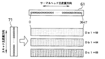
まず、ステップ1(以降、S1とする)において、記録部20により所定の階調値で図6に示す帯状の画像パターンをそれぞれ記録する。例えば256階調の画像データに対しては、0と255の中間である64, 128, 192の3段階をサンプル階調値Di(i=1〜3)として選択する(ただし、D0=0,D4=255)。そして、最小階調値D0と最大階調値D4を除く他の3つのサンプル階調値D1,D2,D3に対し、階調値Diと、階調値Diに所定階調幅(例えば5階調)を加算及び減算した階調値Di±5の合計3つの階調値、即ち、Dai(=Di-5),Dbi(=Di),Dci(=Di+5)を設定する。つまり、1つのサンプル階調値に対して3つの階調値からなる設定階調値を1組設定する。この設定階調値の組を3つのサンプル階調値に対して設定することで、合計3組、即ち9つの階調値を設定する。
【0020】
尚、本実施の形態においては、サンプル階調値を3段階(D1,D2,D3)として設定しているが、これに限定されることなく、計算処理の簡便化のために段階数を減らしたり、補正値の設定精度向上のために増加させてもよい。また、上記所定階調幅は5階調として設定しているが、この値は使用する画像データに応じて適宜変更して設定することが望ましい。さらに、所定階調幅の加算・減算のうちどちらか一方だけを設定し、所定の階調値と加算又は減算した階調値との2つの階調値を1組として以降の処理を行ってもよい。そしてさらに、サンプル階調値を中心とする複数(例えば、所定の階調値±5及び±10の合計5つ)の階調値を設定し、これら複数の階調値を1組として処理してもよい。いずれに対しても補正精度と処理時間との兼ね合いから決定することが望ましい。
【0021】
図6(a)は、サンプル階調値D1に対する3つの設定階調値による記録結果で、記録装置の主走査方向(発熱抵抗体位置H=0〜3647)に亘って記録した結果を示している。同様に図6(b)及び(c)は、それぞれサンプル階調値D2,D3対する記録結果を示している。それぞれの帯状パターン内の印画濃度は、理想的には画像データの階調値である設定階調値に相当する濃度で均一となるが、実際の記録結果は、印画濃度が設定階調値に相当する濃度からずれたり、記録位置によって印画濃度が異なることがあり、主走査方向の濃度ムラを生じる場合がある。
ここでは説明の簡単のため、サンプル階調値が64の場合(D1=64)を例にとり説明することにする。補正基準となる画像パターンの階調値を表す設定階調値をDa1=59(=D1-5)、Db1=64(=D1),Dc1=69(=D1+5)として、図7に示すように、それぞれ帯状にサーマルヘッド61の主走査方向の全面(3648個の発熱抵抗体を有するサーマルヘッドの最大記録幅)に亘って、設定階調値Da1,Db1,Dc1のパターンを順次記録する。
【0022】
次に、S2において、図7に示すラインセンサを有するスキャナ71を、そのスキャナ71の主走査方向がサーマルヘッド61の主走査方向に略直交するように設置して、サーマルヘッド61の主走査方向である矢印方向に走査し、各帯状パターンの印画濃度値La(H),Lb(H),Lc(H)を全画素(スキャナの検出分解能が発熱抵抗体の配列間隔と一致する場合を想定してH=0〜3647画素とする。)に対して検出する。このとき、印画濃度値La(H),Lb(H),Lc(H)は、各帯状パターンの帯幅内の数画素に対する印画濃度値(同一H位置の印画濃度値)を平均化して求めるようにする。これにより、スキャナの各検出素子に対する感度特性のばらつきが平均化されると共に、例えば帯状パターン上に白抜けや黒点、ゴミ等が付着している場合であっても精度良く印画濃度値を検出することができる。
スキャナの検出分解能が発熱抵抗体の配列間隔と一致しない場合は、公知の方法により解像度変換処理を行えばよい。また、厳密に直交する位置に設置することは困難であるため、印画画像中に位置検知用パターンを配しておき、このパターンを基準として画像の回転及び解像度変換処理を行うことが好ましい。
スキャナ71の走査により得られる印画濃度値La(H),Lb(H),Lc(H)は、例えば図8に示すような濃度分布を呈する。図8に示すように、印画濃度値La(H),Lb(H),Lc(H)は、設定階調値Da1,Db1,Dc1からの絶対値のずれが生じており、このずれ量は各画素毎に異なると共に、各設定階調値毎に対しても異なっている。このため、設定した階調値に対応した濃度に均一化するためには、各画素毎、及び各階調毎にそれぞれ補正処理を施す必要がある。
【0023】
S3においては、スキャナの走査により得られた印画濃度値La(H),Lc(H)の、全画素に対する平均値LaAV,LbAV,LcAVをそれぞれ求める。
次いで、S4において補正係数Ri(ここではi=1)を求める。この補正係数Riは、サンプル階調値近傍における階調値と印画濃度値との比であって(1)式により算出する。
Ri=(Dci―Dai)/(LcAV―LaAV) (1)
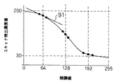
ここで、図9に設定した階調値に対するスキャナ検出濃度値の関係を示す。図9において、補正係数Riは各サンプル階調値近傍のスキャナ検出濃度の変化、即ち、傾き91を表すものである。
【0024】
次に、S5においては、S4で得られたRiを用いて印画濃度値を適正に補正するための階調補正値Xi(H)を(2)式により算出する。
Xi(H)=Di―{LbAV―Lb(H)}Ri (2)
これにより、サンプル階調値D1=64における全画素に対する印画濃度補正値が求まる。
【0025】
以上の階調補正値Xi(H)の算出処理を各サンプル階調値Di(i=1,2,3)全てに対して行う(S6、S7)。このように、スキャナを帯状パターンの長手方向に沿って相対的に走査させて印画濃度を検出し、得られた印画濃度値と階調値をとの比に基づく補正係数を用いて階調補正値を算出することにより、例えば、異なる種類のスキャナを使用した場合や、主走査方向に感度特性のムラがあるスキャナを使用した場合であっても同様にして精度よく階調補正値を決定することができる。
全サンプル階調値Di(i=1,2,3)に対して階調補正値をXi(H)を算出した後は、図10に示すように各サンプル階調値Diに対する階調補正値が全画素に対して求まる。図10にはH=0, 1800, 3647の3点の画素に対してのみ階調補正値を表示している。尚、サンプル階調値D0,D4に対する階調補正値は、それぞれ全画素に亘って0,255に設定している。
【0026】
そして、S8において、S5で得られた各サンプル階調値における離散的な階調補正値Xi(H)を基にして、全階調に対する階調補正値x(H)を近似的に求める。具体的には、同一画素(例えばH=0の画素)の階調補正値X0(0), X1(0), X2(0), X3(0), X4(0)を用いて、各サンプル階調値間の階調補正値を、例えば、線形補間、スプライン補間、あるいは一般的な任意の関数による補間処理を施すことにより内挿して、全階調に対する階調補正値x(H)を求める。このような補間処理により実用上十分な精度で階調補正値を求めることができ、階調補正値の算出処理を簡略化することができる。
【0027】
さらに、S9において、図11に示すような記録装置主走査方向の全画素、即ち、H=0〜3647の各画素に対して、全階調値、即ち、0〜255の全階調に対応する階調補正値x(H)を示す対応テーブルを補正値テーブル格納部2に格納する。 ここにおいて、上記階調補正値は直接的に画像の階調値として設定されるため、階調補正値を整数化しておく必要がある。この整数化の手法として、次に示す2つの方法を一例として揚げておく。
第1の方法は、単純に小数を四捨五入して整数化する方法である。
第2の方法は、確率的手法に基づいて変換する方法で、例えば、小数点以下を含む階調補正値が128.5であった場合、副走査方向のライン位置が偶数ライン位置の場合には補正値を128とし、奇数ライン位置の場合には129になるようにしてもよい。この処理の具体的な方法としては、まず、小数点を含む全ての階調補正値を4倍し、4倍された補正値の小数点以下を切り捨てる。これにより、0〜255の階調補正値の階調範囲を、0〜1020の階調範囲に拡張する。即ち、図12に示す補正値テーブルが作成され、0〜255の階調補正値の印画階調データを、まず0〜1020の階調データに変換する。
次に、印画位置によって決定される0〜3の値を加算値として0〜1020のデータに加算することで、0〜1023の階調範囲の値に変換する。
そして、この値を4で除算して小数点以下を切り捨てる。前記加算値としては、例えば図13に示すマトリクスを用いて決定すればよい。以上の処理により階調補正値が整数化される。
ここにおいて、図13に示すpはヒータ位置Hを4で除算した余りに対応し、qは副走査ライン位置を4で除算した余りに対応している。例えば、ヒータ位置が105番目、副走査ライン位置が63番目の場合はp=1、q=3となり、図13から加算値として1が決定される。
上記のことから、階調補正値が128.3の場合について補正値を整数化することを考えると、まず128.3を4倍して小数点以下を切り捨てることで補正値は513に変換される。次に、図13を参照して印画位置に応じた加算値を加算する。加算後に4で除算し、さらに小数点以下を切り捨てる。
即ち、加算値が0の印画位置では128、1の印画位置では128、2の印画位置では128、3の印画位置では129にそれぞれ変換される。加算値0〜3は等しい確率で出現するため、補正値128.3は3/4の確率で128に、1/4の確率で129に変換されることになる。
尚、上記説明では4で乗算及び除算するという表現を用いたが、実際には、2進法による表示形態においては小数点位置が異なるだけであるため、実際に乗算及び除算演算を行う必要はない。例えば、10bitで表現された0〜1023の値に対して下位2bitを無視し(ハードウェア的に接続せずに)、上位8bitのみを用いれば、「4で除算して小数点以下を切り捨てた」ことと同等になる。このため膨大なデータであっても高速に整数化することができる。
【0028】
次に、入力された画像データの画像形成を行うステップを説明する。
まず、S10において、外部から画像データを画像補正制御部1に入力する。これは、例えば光磁気ディスク、フロッピーディスク等の記憶媒体に保存されている画像データを読み出したり、外部機器との通信により画像データを取り込むことで入力する。
そして、S11において、入力された画像データの各画素値に対して、補正値テーブル格納部2に格納されている補正値テーブルを参照し、画像データの対応する画素、及び対応する階調値に相当する階調補正値を読み込み、この階調補正値を画像メモリ3に出力して画像メモリ3上に補正画像データを構築する。
【0029】
次に、S12において、画像メモリ2に記憶された補正画像データを、画像補正制御部1からの記録指令によりサーマルヘッド61側に出力し、補正画像データを感熱フィルムA上に形成する。
このようにして形成された補正画像データによる記録画像は、サーマルヘッド61の主走査方向に対する濃度ムラが全画素及び全階調値に対して適正に補正されているため、ムラのない高品質の画像として得られるようになる。
【0030】
以上説明したように、本実施の形態においては、所定の階調で記録した印画濃度をサーマルヘッドの主走査方向にスキャナを走査して検出することにより、主走査方向の濃度ムラを同じ条件で測定することができ、精度良く印画濃度を検出することができる。さらに、スキャナの複数の検出素子からの検出濃度を平均化して印画濃度値を求めるため、検出精度をより向上させることができる。このため、スキャナの主走査方向に感度特性のムラがあっても、また、校正されていないスキャナであってもサーマルヘッドの主走査方向に現れる濃度ムラを精度よく補正することができる。
【0031】
【発明の効果】
本発明によれば、それぞれ複数の異なる階調で記録された複数の帯状パターンの印画濃度をライン型ヘッドの主走査方向に沿ってラインセンサを相対的に移動して検出し、補正することで、印画濃度の検出誤差を低減することができると共に、ラインセンサの個体差やラインセンサの検出素子毎に異なる感度特性に影響されることなく、安定して階調補正値を検出することができ、精度良く濃度ムラを補正することができる。また、離散的に設定された階調値に対する補正条件を全階調に対して内挿して求めることにより、全階調分の印画濃度を逐一検出することなく、簡便にして実用上十分な精度で補正条件を設定することができる。
【図面の簡単な説明】
【図1】本実施の形態に係る画像記録装置の構成を示す概念図。
【図2】図1の画像記録装置のプリント動作時の説明図。
【図3】図1の画像記録装置のレシーバーシート排出時の説明図。
【図4】本実施の形態に係る画像記録装置の記録部の構成を示す概念図。
【図5】濃度ムラを補正して画像を形成する手順を示すフローチャート。
【図6】各サンプル階調値の設定階調値で記録した帯状パターンを示す図。
【図7】記録装置の主走査方向とスキャナの主走査方向との関係を示す図。
【図8】各設定階調値の印画濃度の検出値の分布を示す図。
【図9】各設定階調値に対するスキャナの検出濃度値の関係を示す図。
【図10】入力される画像データの階調値に対する階調補正値を示す図。
【図11】補正値テーブルの内容を示す図。
【図12】補正値テーブルの中間処理状態の内容を示す図。
【図13】加算値のマトリクスの内容を示す図。
【符号の説明】
1 画像補正制御部
2 補正値テーブル格納部
3 画像メモリ
61 サーマルヘッド
71 スキャナ[0001]
BACKGROUND OF THE INVENTION
The present invention relates to a technique for correcting recording density unevenness in image recording using a line-type head.
[0002]
[Prior art]
When a printing plate is created from a color document and a large number of sheets are printed, the proof is first printed, and the final printing is performed after confirming the finish. In the proof process, a color proof is created and the image quality of this color proof is confirmed. This color proof is obtained by transferring an image formed on the receiver sheet to a main sheet after thermally transferring the image to the receiver sheet with a thermal printer.
Here, as is well known, in an image recording apparatus such as a thermal printer, a glaze formed by arranging heating resistors corresponding to the number of pixels in one line in one direction (main scanning direction) is used as a printing medium. The glaze and the printing medium are relatively moved in the sub-scanning direction substantially orthogonal to the arrangement direction of the heating resistors in a slightly pressed state, and each of the glaze heating resistors is heated according to the image data of the recorded image. Thus, a recorded image is formed by thermally transferring an image to a print medium.
[0003]
In an image recording apparatus of such a recording method, for example, when a recorded image is formed using image data having a predetermined same gradation value, the density differs for each heating resistor of the formed recorded image. Recording density unevenness such as shading may occur. This is inevitable because the glaze shape of the line-type head is not necessarily uniform. Depending on the image processing apparatus, density unevenness correction is performed on image data in advance in order to prevent image quality deterioration due to density unevenness. Is going.
As a specific example of this density unevenness correction method, for example, there is the following method.
First, image recording is performed with image data of uniform gradation in the main scanning direction of the line type head. Then, the print density is detected by relatively scanning (moving) a densitometer such as a scanner in the sub-scanning direction of the line-type head with respect to the recorded image, and the obtained print density for each pixel is obtained from the image data. Compared with the gradation value, the gradation value of the image data is corrected.
[0004]
[Problems to be solved by the invention]
However, in such a conventional density unevenness correction method, since each of the detection elements of the scanner detects the print density at a different position of the recorded image, the print density depends on the sensitivity characteristics of the individual detection elements of the scanner. The value may change. In general, the sensitivity characteristics of the detection elements of the scanner are not strictly uniform, so that the print densities that should originally be detected are detected as different density values. As a result, there is a problem that the correction value set based on the detected print density value becomes an incorrect value and proper density unevenness correction cannot be performed.
The present invention has been made in view of such conventional problems, and a density unevenness correction method capable of accurately correcting density unevenness without being affected by sensitivity characteristics inherent to the scanner and an image using the method. A recording apparatus is provided.
[0005]
[Means for Solving the Invention]
In order to achieve the above object, the present invention is a density unevenness correction method in image recording using a line type head, which prints a belt-like pattern with a predetermined gradation value in the main scanning direction of the line type head. The main scanning direction of the line-type head is aligned with the sub-scanning direction of the line-type head, and the line sensor is relatively moved along the main-scanning direction of the line-type head to detect the print density of the belt-like pattern, Correction conditions for each pixel position are obtained based on the print density value and the predetermined gradation value, and image data for image recording is corrected according to the correction condition.
[0006]
Here, the band-shaped pattern includes a plurality of band-shaped patterns printed with at least two gradation values selected in the vicinity of a predetermined gradation value, and the correction condition is a print density value for the plurality of band-shaped patterns. The average value of each is obtained, and the average value obtained is based on the rate of change with respect to the gradation value of each strip pattern Set. For example, in the case of a belt-like pattern printed with two gradation values, a correction condition is set based on the ratio of the difference between the average values of the print density values and the difference between the gradation values, and three or more gradations are set. In the case of a belt-like pattern printed with values, a change rate is obtained by performing linear approximation or the like on the distribution of each print density value with respect to each gradation value, and a correction condition is set based on this change rate.
[0007]
The band-shaped pattern includes two band-shaped patterns printed with a first gradation value that is the predetermined gradation value and a second gradation value close to the first gradation value, and the correction condition includes the first gradation value. It is preferable to set based on the ratio of the difference between the average values of the print density values with respect to the belt-like pattern of the second gradation value and the difference between the first and second gradation values.
[0008]
Further, the predetermined gradation value is any one gradation value obtained by equally dividing the gradation range up to the maximum gradation value into a plurality of stages, and is based on individual correction conditions set for each stage. It is preferable to set the correction conditions for all gradations by interpolating. For example, in the case of image data of 256 gradations, five gradation values of 0, 64, 128, 192, and 255 are set by dividing the range from 0 to 255 into four equal parts, and 0 and 255 are not corrected, and each floor of 64, 128, and 192 is corrected. A correction condition for the tone value is obtained, and the correction condition for each of the 0 to 255 gradations is interpolated based on the obtained individual correction conditions to be obtained approximately and set.
[0009]
In addition, a correction value table storage unit that stores a correction value table for gradation value correction determined based on the print density value of the printed image pattern, and image data corrected by the correction value table are stored. An image recording apparatus comprising an image memory and an image correction control unit that controls image data correction processing, wherein the correction value table storage unit is based on the method according to any one of
[0010]
Further, it contains 30 to 70 parts by weight of pigment and 25 to 60 parts by weight of an amorphous organic polymer having a softening point of 40 to 150 ° C., and the film thickness is in the range of 0.2 to 1.0 μm. It has a substantially transparent thermal ink layer, the particle size of 70% or more of the pigment in the thermal ink layer is 1.0 μm or less, and the optical reflection density of the transferred image is at least 1 on the white support. Recording was performed with a thermal head on a thermal transfer recording material of 0 or more.
[0011]
DETAILED DESCRIPTION OF THE INVENTION
Embodiments according to the present invention will be described below with reference to FIGS. FIG. 1 conceptually shows the main configuration of an image recording apparatus according to an embodiment of the present invention, FIG. 2 is an explanatory diagram during the printing operation of the image recording apparatus of FIG. 1, and FIG. FIG. 2 is an explanatory diagram when the receiver sheet is discharged from the image recording apparatus of FIG. 1.
This image recording apparatus 10 (hereinafter referred to as recording apparatus 10) is configured as a recording apparatus with a built-in laminator by providing a pressure / heating roller pair in the sheet conveyance path of the recording apparatus. The
[0012]
The sheet feeding cassette 6310 is provided with a
The pair of pressurizing /
A
[0013]
The operation of the laminator-equipped
At the time of printing, as shown in FIG. 2, after one
[0014]
After the printing on the
Next, the
[0015]
The leading end of the
The pressure / heating
[0016]
On the other hand, as shown in FIG. 3, the
In this delivery step, the heat roller on the back side (left side in the figure) can be kept away. In this case, the receiver sheet to be printed next is heated in advance, so that the substance on the recording surface of the receiver sheet is stabilized, and the recording sensitivity is stabilized.
In addition, when the transfer process to the
[0017]
Next, the
A
The
The
The
[0018]
When recording an image with this recording apparatus, the predetermined transfer start position of the
Along with this conveyance, transfer recording is performed on the
Here, the image data correction control system for correcting the image data of the recorded image in the recording apparatus of the present embodiment corrects the input image data and generates the corrected image data, and the image data The correction value
[0019]
Next, a method for correcting image data by such an image data correction control system will be described with reference to the flowchart shown in FIG. The density unevenness correction method according to the present embodiment is generally based on the ratio between the obtained print density value and the gradation value by detecting the print density value of the image pattern recorded with a predetermined gradation value. Thus, the correction value of the gradation value of the image data is determined. A detailed processing procedure will be described below.
First, in step 1 (hereinafter referred to as S1), the
[0020]
In this embodiment, the sample gradation value is set as three stages (D1, D2, D3). However, the present invention is not limited to this, and the number of stages is reduced to simplify the calculation process. Or may be increased to improve the setting accuracy of the correction value. The predetermined gradation width is set as 5 gradations, but it is desirable to set this value by appropriately changing according to the image data to be used. Further, only one of addition / subtraction of a predetermined gradation width is set, and the subsequent processing is performed with two gradation values of a predetermined gradation value and the gradation value added or subtracted as one set. Good. Further, a plurality of gradation values (for example, a total of five predetermined gradation values ± 5 and ± 10) are set around the sample gradation value, and the plurality of gradation values are processed as one set. May be. In any case, it is desirable to determine the balance between the correction accuracy and the processing time.
[0021]
FIG. 6 (a) shows the result of recording over the main scanning direction (heating resistor position H = 0 to 3647) of the recording apparatus as a result of recording with three set gradation values with respect to the sample gradation value D1. Yes. Similarly, FIGS. 6B and 6C show the recording results for the sample gradation values D2 and D3, respectively. The print density in each band pattern is ideally uniform at a density corresponding to the set gradation value, which is the gradation value of the image data, but the actual recording result is that the print density is the set gradation value. The print density may deviate from the corresponding density, or the print density may vary depending on the recording position, resulting in density unevenness in the main scanning direction.
Here, for simplicity of explanation, a case where the sample gradation value is 64 (D1 = 64) will be described as an example. FIG. 7 shows the set gradation values representing the gradation values of the image pattern serving as the correction reference as Da1 = 59 (= D1-5), Db1 = 64 (= D1), and Dc1 = 69 (= D1 + 5). As described above, the patterns of the set gradation values Da1, Db1, and Dc1 are sequentially recorded over the entire surface of the
[0022]
Next, in S2, the
If the detection resolution of the scanner does not match the arrangement interval of the heating resistors, resolution conversion processing may be performed by a known method. In addition, since it is difficult to install them at positions that are strictly orthogonal, it is preferable to place a position detection pattern in the print image and perform image rotation and resolution conversion processing based on this pattern.
The print density values La (H), Lb (H), and Lc (H) obtained by scanning with the
[0023]
In S3, average values LaAV, LbAV, and LcAV for all the pixels of the print density values La (H) and Lc (H) obtained by scanning with the scanner are obtained.
Next, in S4, a correction coefficient Ri (here i = 1) is obtained. The correction coefficient Ri is a ratio between the gradation value and the print density value in the vicinity of the sample gradation value, and is calculated by the equation (1).
Ri = (Dci-Dai) / (LcAV-LaAV) (1)
Here, the relationship between the scanner detection density value and the gradation value set in FIG. 9 is shown. In FIG. 9, the correction coefficient Ri represents the change in the density detected by the scanner in the vicinity of each sample gradation value, that is, the
[0024]
Next, in S5, a gradation correction value Xi (H) for appropriately correcting the print density value using Ri obtained in S4 is calculated by the equation (2).
Xi (H) = Di- {LbAV-Lb (H)} Ri (2)
As a result, the print density correction value for all the pixels at the sample gradation value D1 = 64 is obtained.
[0025]
The above calculation processing of the gradation correction value Xi (H) is performed for all the sample gradation values Di (i = 1, 2, 3) (S6, S7). As described above, the scanner is relatively scanned along the longitudinal direction of the belt-like pattern to detect the print density, and the gradation correction is performed using the correction coefficient based on the ratio between the obtained print density value and the gradation value. By calculating the value, for example, even when a different type of scanner is used or a scanner having uneven sensitivity characteristics in the main scanning direction is used, the gradation correction value is accurately determined in the same manner. be able to.
After calculating the gradation correction value Xi (H) for all the sample gradation values Di (i = 1, 2, 3), the gradation correction value for each sample gradation value Di as shown in FIG. Is obtained for all pixels. In FIG. 10, gradation correction values are displayed only for three pixels of H = 0, 1800, and 3647. Note that the tone correction values for the sample tone values D0 and D4 are set to 0 and 255 over all the pixels, respectively.
[0026]
In S8, the tone correction value x (H) for all tones is approximately obtained based on the discrete tone correction value Xi (H) in each sample tone value obtained in S5. Specifically, the tone correction values X0 (0), X1 (0), X2 (0), X3 (0), and X4 (0) of the same pixel (for example, pixel with H = 0) are used for each sample. The gradation correction value x (H) for all gradations is interpolated by, for example, interpolating gradation correction values between gradation values by performing interpolation processing using linear interpolation, spline interpolation, or a general arbitrary function. Ask. With such an interpolation process, the gradation correction value can be obtained with practically sufficient accuracy, and the gradation correction value calculation process can be simplified.
[0027]
Further, in S9, all gradation values, that is, all gradations from 0 to 255, are supported for all pixels in the recording apparatus main scanning direction as shown in FIG. A correspondence table indicating the gradation correction value x (H) to be stored is stored in the correction value
The first method is a method of rounding off decimals to make an integer.
The second method is a conversion method based on a probabilistic method. For example, when the gradation correction value including the decimal point is 128.5, the correction value is obtained when the line position in the sub-scanning direction is an even line position. May be 128, and may be 129 in the case of odd line positions. As a specific method of this process, first, all the gradation correction values including the decimal point are quadrupled, and the decimal part of the corrected value that has been quadrupled is rounded down. As a result, the gradation range of the gradation correction value from 0 to 255 is expanded to the gradation range from 0 to 2020. That is, the correction value table shown in FIG. 12 is created, and the print gradation data having gradation correction values of 0 to 255 is first converted to gradation data of 0 to 1,020.
Next, the
Then, this value is divided by 4 and the decimal part is rounded down. The addition value may be determined using, for example, a matrix shown in FIG. The gradation correction value is converted to an integer by the above processing.
Here, p shown in FIG. 13 corresponds to the remainder obtained by dividing the heater position H by 4, and q corresponds to the remainder obtained by dividing the sub-scan line position by 4. For example, when the heater position is 105th and the sub-scanning line position is 63rd, p = 1 and q = 3, and 1 is determined as the addition value from FIG.
From the above, considering that the correction value is converted into an integer when the gradation correction value is 128.3, the correction value is first converted to 513 by multiplying 128.3 by 4 and rounding off the decimal part. Next, an added value corresponding to the print position is added with reference to FIG. After addition, divide by 4 and round down after the decimal point.
That is, 128 is converted at the print position where the addition value is 0, 128 at the print position of 1, 128 at the print position of 2, and 129 at the print position of 3. Since the addition values 0 to 3 appear with equal probability, the correction value 128.3 is converted to 128 with a probability of 3/4 and 129 with a probability of 1/4.
In the above description, the expression “multiply and divide by 4” is used. However, in actuality, only the decimal point position is different in the binary display form, so it is not necessary to actually perform multiplication and division operations. . For example, if the lower 2 bits are ignored (without hardware connection) and only the upper 8 bits are used for the value of 0 to 1023 expressed in 10 bits, "Division by 4 and truncation after the decimal point" It becomes equivalent to that. For this reason, even a huge amount of data can be converted to an integer at high speed.
[0028]
Next, steps for forming an image of input image data will be described.
First, in S10, image data is input to the image
In step S11, the correction value table stored in the correction value
[0029]
Next, in S12, the corrected image data stored in the
In the recorded image based on the corrected image data formed in this way, the density unevenness in the main scanning direction of the
[0030]
As described above, in the present embodiment, density unevenness in the main scanning direction is detected under the same conditions by detecting the print density recorded at a predetermined gradation by scanning the scanner in the main scanning direction of the thermal head. It is possible to measure the print density with high accuracy. Furthermore, the detection density from the plurality of detection elements of the scanner is averaged to obtain the print density value, so that the detection accuracy can be further improved. For this reason, even if the sensitivity characteristic is uneven in the main scanning direction of the scanner, or even if the scanner is not calibrated, the density unevenness appearing in the main scanning direction of the thermal head can be accurately corrected.
[0031]
【The invention's effect】
According to the present invention, Multiple different each Recorded with gradation Multiple strip patterns The print density is detected by relatively moving the line sensor along the main scanning direction of the line head. And correct As a result, the detection error of the print density can be reduced, and the gradation correction value can be detected stably without being affected by the individual characteristics of the line sensors or the sensitivity characteristics that differ for each detection element of the line sensors. Density unevenness can be corrected with high accuracy. In addition, the correction conditions for discretely set gradation values are interpolated and obtained for all gradations, so that the print density for all gradations can be detected easily and practically with sufficient accuracy. The correction conditions can be set with.
[Brief description of the drawings]
FIG. 1 is a conceptual diagram showing a configuration of an image recording apparatus according to an embodiment.
2 is an explanatory diagram of a printing operation of the image recording apparatus of FIG.
FIG. 3 is an explanatory diagram when the receiver sheet is discharged from the image recording apparatus of FIG. 1;
FIG. 4 is a conceptual diagram showing a configuration of a recording unit of the image recording apparatus according to the present embodiment.
FIG. 5 is a flowchart illustrating a procedure for forming an image by correcting density unevenness.
FIG. 6 is a diagram showing a belt-like pattern recorded with a set gradation value of each sample gradation value.
FIG. 7 is a diagram illustrating a relationship between a main scanning direction of the recording apparatus and a main scanning direction of the scanner.
FIG. 8 is a diagram illustrating a distribution of print density detection values for each set gradation value.
FIG. 9 is a diagram showing a relationship of a detected density value of a scanner with respect to each set gradation value.
FIG. 10 is a diagram illustrating a gradation correction value with respect to a gradation value of input image data.
FIG. 11 is a view showing the contents of a correction value table.
FIG. 12 is a diagram showing the contents of an intermediate processing state of a correction value table.
FIG. 13 is a diagram showing the contents of a matrix of added values.
[Explanation of symbols]
1 Image correction controller
2 Correction value table storage
3 Image memory
61 Thermal head
71 scanner
Claims (5)
ライン型ヘッドの主走査方向に所定の階調値で帯状パターンを印画し、ラインセンサの主走査方向を前記ライン型ヘッドの副走査方向に合わせ、ラインセンサをライン型ヘッドの主走査方向に沿って相対的に移動することで前記帯状パターンの印画濃度を検出し、該検出した各印画濃度値と前記所定の階調値に基づいて各画素位置に対する補正条件をそれぞれ求め、該補正条件に応じて画像記録用の画像データを補正するに際し、
前記帯状パターンは、所定の階調値の近傍に選定された少なくとも2つの階調値で印画された複数の帯状パターンを含み、
前記補正条件は、前記複数の帯状パターンに対する印画濃度値の平均値をそれぞれ求め、得られた各平均値の各帯状パターンの階調値に対する変化割合に基づいて設定することを特徴とする濃度ムラ補正方法。 In the density unevenness correction method in image recording using a line type head,
A belt-like pattern is printed with a predetermined gradation value in the main scanning direction of the line type head, the main scanning direction of the line sensor is aligned with the sub-scanning direction of the line type head, and the line sensor is aligned with the main scanning direction of the line type head. The print density of the belt-like pattern is detected by relatively moving the image, and correction conditions for the respective pixel positions are obtained based on the detected print density values and the predetermined gradation values, respectively. When correcting image data for image recording ,
The strip pattern includes a plurality of strip patterns printed with at least two tone values selected in the vicinity of a predetermined tone value;
The correction condition is obtained by determining an average value of the print density values for the plurality of strip patterns, and setting based on a change ratio of each obtained average value to the gradation value of each strip pattern. Correction method.
Priority Applications (4)
| Application Number | Priority Date | Filing Date | Title |
|---|---|---|---|
| JP33719097A JP3703061B2 (en) | 1997-12-08 | 1997-12-08 | Density unevenness correction method and image recording apparatus using the method |
| EP98123282A EP0922585B1 (en) | 1997-12-08 | 1998-12-07 | Method for correcting density irregularity and image recording apparatus using the method |
| US09/206,288 US6313857B1 (en) | 1997-12-08 | 1998-12-07 | Method for correcting density irregularity and image recording apparatus using the method |
| DE69824941T DE69824941T2 (en) | 1997-12-08 | 1998-12-07 | Method of correcting irregularities in density and image recording apparatus by this method |
Applications Claiming Priority (1)
| Application Number | Priority Date | Filing Date | Title |
|---|---|---|---|
| JP33719097A JP3703061B2 (en) | 1997-12-08 | 1997-12-08 | Density unevenness correction method and image recording apparatus using the method |
Publications (2)
| Publication Number | Publication Date |
|---|---|
| JPH11170589A JPH11170589A (en) | 1999-06-29 |
| JP3703061B2 true JP3703061B2 (en) | 2005-10-05 |
Family
ID=18306300
Family Applications (1)
| Application Number | Title | Priority Date | Filing Date |
|---|---|---|---|
| JP33719097A Expired - Fee Related JP3703061B2 (en) | 1997-12-08 | 1997-12-08 | Density unevenness correction method and image recording apparatus using the method |
Country Status (4)
| Country | Link |
|---|---|
| US (1) | US6313857B1 (en) |
| EP (1) | EP0922585B1 (en) |
| JP (1) | JP3703061B2 (en) |
| DE (1) | DE69824941T2 (en) |
Families Citing this family (13)
| Publication number | Priority date | Publication date | Assignee | Title |
|---|---|---|---|---|
| JP2002142113A (en) * | 2000-10-30 | 2002-05-17 | Canon Inc | Image processor, image processing system, image processing method, and recording medium |
| JP2002264412A (en) * | 2001-03-14 | 2002-09-18 | Canon Inc | Method for processing image, program and image processor |
| EP1457345B1 (en) * | 2003-03-12 | 2009-12-30 | Agfa HealthCare NV | Thermal head printer and process for printing substantially light-insensitve recording materials. |
| US7139010B2 (en) | 2003-03-12 | 2006-11-21 | Agfa Gevaert | Thermal head printer and process for printing substantially light-insensitive recording materials |
| WO2004100529A1 (en) * | 2003-05-08 | 2004-11-18 | Seiko Epson Corporation | Image processing for expressing gradation |
| US7661787B2 (en) | 2004-02-13 | 2010-02-16 | Seiko Epson Corporation | Printing method, computer-readable medium, printing apparatus, method of manufacturing printing apparatus, printing system, and correction pattern |
| JP2007151075A (en) * | 2005-10-31 | 2007-06-14 | Seiko Epson Corp | Printer, printing method, image processing apparatus, image processing method, printing program, image processing program, and recording medium |
| JP5996469B2 (en) * | 2013-03-28 | 2016-09-21 | シチズンホールディングス株式会社 | Printer |
| JP6070610B2 (en) * | 2014-03-17 | 2017-02-01 | 株式会社Jvcケンウッド | Gradation data generation apparatus and method |
| EP3202579B1 (en) * | 2014-09-29 | 2019-11-13 | Citizen Watch Co., Ltd. | Thermal transfer printer and printing method using same |
| CN108215516B (en) * | 2016-12-22 | 2021-05-11 | 佳能精技立志凯株式会社 | Image forming apparatus, recording medium, and image forming system |
| DE112019004537T5 (en) | 2018-09-11 | 2021-09-23 | Sony Corporation | DRAWING METHOD, HEAT SENSITIVE RECORDING MEDIUM, AND DRAWING DEVICE |
| CN113344819A (en) * | 2021-06-24 | 2021-09-03 | 浙江汇诚汇捷影像数码科技有限公司 | Method and system for adjusting gray scale curve of thermal sensitive film imaging |
Family Cites Families (10)
| Publication number | Priority date | Publication date | Assignee | Title |
|---|---|---|---|---|
| JP2854318B2 (en) * | 1989-04-28 | 1999-02-03 | キヤノン株式会社 | Image recording device |
| US5202773A (en) * | 1989-12-22 | 1993-04-13 | Fuji Xerox Co., Ltd. | Multiple value image input device with chromatic gradation correction |
| JPH0832462B2 (en) * | 1990-02-27 | 1996-03-29 | 三菱電機株式会社 | Gradation recording printer |
| DE69132839T2 (en) * | 1990-05-11 | 2002-04-25 | Canon Kk | Recording device with test sample reader |
| JP3274200B2 (en) | 1992-12-28 | 2002-04-15 | キヤノン株式会社 | Image forming method and apparatus |
| EP0743195B1 (en) * | 1995-05-15 | 1999-08-11 | Fuji Photo Film Co., Ltd. | Image forming assembly and image receiving sheet |
| JPH09234899A (en) * | 1996-02-29 | 1997-09-09 | Fuji Photo Film Co Ltd | Thermosensitive recording device |
| DE69702362T2 (en) * | 1996-04-01 | 2000-10-26 | Fuji Photo Film Co Ltd | Heat recording method and device |
| JPH1051635A (en) * | 1996-07-31 | 1998-02-20 | Fuji Photo Film Co Ltd | Image recorder |
| JPH10286986A (en) * | 1997-04-14 | 1998-10-27 | Fuji Photo Film Co Ltd | Method for correcting uneven density |
-
1997
- 1997-12-08 JP JP33719097A patent/JP3703061B2/en not_active Expired - Fee Related
-
1998
- 1998-12-07 US US09/206,288 patent/US6313857B1/en not_active Expired - Lifetime
- 1998-12-07 DE DE69824941T patent/DE69824941T2/en not_active Expired - Lifetime
- 1998-12-07 EP EP98123282A patent/EP0922585B1/en not_active Expired - Lifetime
Also Published As
| Publication number | Publication date |
|---|---|
| JPH11170589A (en) | 1999-06-29 |
| DE69824941T2 (en) | 2004-12-16 |
| EP0922585B1 (en) | 2004-07-07 |
| DE69824941D1 (en) | 2004-08-12 |
| EP0922585A2 (en) | 1999-06-16 |
| US6313857B1 (en) | 2001-11-06 |
| EP0922585A3 (en) | 2000-03-15 |
Similar Documents
| Publication | Publication Date | Title |
|---|---|---|
| JP3703061B2 (en) | Density unevenness correction method and image recording apparatus using the method | |
| US10005291B2 (en) | Thermal transfer printer and method for controlling the same | |
| JP5926567B2 (en) | Thermal printer and protective coat printing method | |
| JP3976315B2 (en) | Thermal printer | |
| JPH1044482A (en) | Thermal transfer recording method | |
| US10131157B2 (en) | Image forming apparatus, recording medium and image forming system | |
| JP2004255752A (en) | Ink jet recorder | |
| US8705138B2 (en) | Image forming apparatus including an image calibration system | |
| JPH11129582A (en) | Image forming system | |
| JP3144676B2 (en) | Image forming control device and image forming device | |
| JP3665704B2 (en) | Image forming apparatus | |
| JP2005212344A (en) | Image forming device, and thermal control method for thermal head of the image forming device | |
| JP3359767B2 (en) | Thermal transfer recording device | |
| JP2004009673A (en) | Image formation device | |
| JP3716982B2 (en) | Image forming apparatus | |
| JPH05201108A (en) | Ink sheet and printer apparatus using said ink sheet | |
| JP2000071505A (en) | Thermal printer | |
| EP1980405B1 (en) | Image forming apparatus and method for forming image | |
| JPH08183192A (en) | Thermal transfer recording device | |
| JP3685147B2 (en) | Image forming apparatus | |
| JP2519711Y2 (en) | Printer device | |
| JP3002800B2 (en) | Method and apparatus for correcting recording density of printer | |
| JP2009051150A (en) | Image forming device and method for controlling the same | |
| JPS63251263A (en) | Image recorder | |
| JPS6030266A (en) | Transfer type thermal recording device |
Legal Events
| Date | Code | Title | Description |
|---|---|---|---|
| A977 | Report on retrieval |
Free format text: JAPANESE INTERMEDIATE CODE: A971007 Effective date: 20050414 |
|
| A131 | Notification of reasons for refusal |
Free format text: JAPANESE INTERMEDIATE CODE: A131 Effective date: 20050420 |
|
| A521 | Written amendment |
Free format text: JAPANESE INTERMEDIATE CODE: A523 Effective date: 20050620 |
|
| TRDD | Decision of grant or rejection written | ||
| A01 | Written decision to grant a patent or to grant a registration (utility model) |
Free format text: JAPANESE INTERMEDIATE CODE: A01 Effective date: 20050713 |
|
| A61 | First payment of annual fees (during grant procedure) |
Free format text: JAPANESE INTERMEDIATE CODE: A61 Effective date: 20050714 |
|
| R150 | Certificate of patent or registration of utility model |
Free format text: JAPANESE INTERMEDIATE CODE: R150 |
|
| S111 | Request for change of ownership or part of ownership |
Free format text: JAPANESE INTERMEDIATE CODE: R313111 |
|
| FPAY | Renewal fee payment (event date is renewal date of database) |
Free format text: PAYMENT UNTIL: 20080729 Year of fee payment: 3 |
|
| R350 | Written notification of registration of transfer |
Free format text: JAPANESE INTERMEDIATE CODE: R350 |
|
| FPAY | Renewal fee payment (event date is renewal date of database) |
Free format text: PAYMENT UNTIL: 20080729 Year of fee payment: 3 |
|
| FPAY | Renewal fee payment (event date is renewal date of database) |
Free format text: PAYMENT UNTIL: 20090729 Year of fee payment: 4 |
|
| FPAY | Renewal fee payment (event date is renewal date of database) |
Free format text: PAYMENT UNTIL: 20090729 Year of fee payment: 4 |
|
| FPAY | Renewal fee payment (event date is renewal date of database) |
Free format text: PAYMENT UNTIL: 20100729 Year of fee payment: 5 |
|
| FPAY | Renewal fee payment (event date is renewal date of database) |
Free format text: PAYMENT UNTIL: 20110729 Year of fee payment: 6 |
|
| FPAY | Renewal fee payment (event date is renewal date of database) |
Free format text: PAYMENT UNTIL: 20110729 Year of fee payment: 6 |
|
| FPAY | Renewal fee payment (event date is renewal date of database) |
Free format text: PAYMENT UNTIL: 20120729 Year of fee payment: 7 |
|
| FPAY | Renewal fee payment (event date is renewal date of database) |
Free format text: PAYMENT UNTIL: 20120729 Year of fee payment: 7 |
|
| FPAY | Renewal fee payment (event date is renewal date of database) |
Free format text: PAYMENT UNTIL: 20130729 Year of fee payment: 8 |
|
| R250 | Receipt of annual fees |
Free format text: JAPANESE INTERMEDIATE CODE: R250 |
|
| R250 | Receipt of annual fees |
Free format text: JAPANESE INTERMEDIATE CODE: R250 |
|
| R250 | Receipt of annual fees |
Free format text: JAPANESE INTERMEDIATE CODE: R250 |
|
| R250 | Receipt of annual fees |
Free format text: JAPANESE INTERMEDIATE CODE: R250 |
|
| LAPS | Cancellation because of no payment of annual fees |