JP3702957B2 - Image processing apparatus, image processing method, and medium on which image processing control program is recorded - Google Patents
Image processing apparatus, image processing method, and medium on which image processing control program is recorded Download PDFInfo
- Publication number
- JP3702957B2 JP3702957B2 JP2002186046A JP2002186046A JP3702957B2 JP 3702957 B2 JP3702957 B2 JP 3702957B2 JP 2002186046 A JP2002186046 A JP 2002186046A JP 2002186046 A JP2002186046 A JP 2002186046A JP 3702957 B2 JP3702957 B2 JP 3702957B2
- Authority
- JP
- Japan
- Prior art keywords
- pixel
- color
- image processing
- pixels
- image
- Prior art date
- Legal status (The legal status is an assumption and is not a legal conclusion. Google has not performed a legal analysis and makes no representation as to the accuracy of the status listed.)
- Expired - Fee Related
Links
- 238000012545 processing Methods 0.000 title claims description 154
- 238000003672 processing method Methods 0.000 title claims description 7
- 238000004364 calculation method Methods 0.000 claims description 37
- 239000003086 colorant Substances 0.000 claims description 27
- 238000001514 detection method Methods 0.000 claims description 9
- 238000003384 imaging method Methods 0.000 claims description 9
- 230000000295 complement effect Effects 0.000 claims description 5
- 238000009499 grossing Methods 0.000 description 91
- 238000000034 method Methods 0.000 description 44
- 238000010586 diagram Methods 0.000 description 20
- 239000011159 matrix material Substances 0.000 description 16
- 230000002093 peripheral effect Effects 0.000 description 9
- 230000000740 bleeding effect Effects 0.000 description 8
- 230000014509 gene expression Effects 0.000 description 8
- 238000004088 simulation Methods 0.000 description 8
- 230000000694 effects Effects 0.000 description 4
- 230000001174 ascending effect Effects 0.000 description 3
- 238000006243 chemical reaction Methods 0.000 description 3
- 230000006870 function Effects 0.000 description 3
- 238000004891 communication Methods 0.000 description 2
- 238000007796 conventional method Methods 0.000 description 2
- 230000007423 decrease Effects 0.000 description 2
- 238000004904 shortening Methods 0.000 description 2
- 238000012935 Averaging Methods 0.000 description 1
- 235000003976 Ruta Nutrition 0.000 description 1
- 240000005746 Ruta graveolens Species 0.000 description 1
- 230000002411 adverse Effects 0.000 description 1
- 239000005018 casein Substances 0.000 description 1
- 230000008030 elimination Effects 0.000 description 1
- 238000003379 elimination reaction Methods 0.000 description 1
- 230000002708 enhancing effect Effects 0.000 description 1
- 230000003287 optical effect Effects 0.000 description 1
- 230000000717 retained effect Effects 0.000 description 1
- 235000005806 ruta Nutrition 0.000 description 1
Images


Description
【0001】
【発明の属する技術分野】
単板式の固体撮像素子を利用して撮像された画像データ等に対して画像処理する画像処理装置、画像処理方法および画像処理制御プログラムを記録した媒体に関する。
【0002】
【従来の技術】
固体撮像素子を利用したデジタルスチルカメラ等においては、単板方式が採用されることが多い。この単板方式では、図23(a)に示すように、固体撮像素子の各画素に対応してR,G,B(赤、緑、青)の各色の色フィルタが所定の割合でモザイク状に配設されており、特にGの色フィルタは千鳥状に配設されて成分比が高くなっている。従って、固体撮像素子の各画素においては、R,G,Bのいずれか一色の色信号しか得られず、各色の色信号を得ることができない。そこで、各画素において直接的に得ることができない色信号を隣接する画素の色信号から補間演算してR,G,B全色の色信号を得て階調データに変換して出力し、この階調データに基づいてディスプレイに表示するなどしている。
【0003】
例えば、図23(a)において、矢印(→)で示す中段の色フィルタに着目する。そして、同図(b)に示すように中央から左半分に光が当たっており(白色部分)、同中央から右半分には光が当たっていない(黒色部分)ものとする。ここにおいて、光があたっている状態の各色の色信号レベルを「1」とし、光が当たっていない状態の同色信号レベルを「0」とすると、RおよびGの色信号レベルは、本来、同図(c)に示す値になるはずである。
【0004】
しかし、上述したように、Rの色フィルタからはGの色信号は直接的には得られないし、Gの色フィルタからはRの色信号は直接的に得られないため、Rの色フィルタに対応する画素のGの色信号については、隣接する画素におけるGの色信号を線形補間して得る。他方、Gの色フィルタに対応する画素のRの色信号については、隣接する画素におけるRの色信号を線形補間して得る。すると、各画素におけるGおよびRの色信号レベルは、それぞれ図23(d)および(e)に示す値となる。図からも明らかなように、光が当たる領域と光が当たらない領域との境界付近の画素に偽の色信号が発生し、この偽の色信号により画像上に色にじみ(偽色と呼ぶこともある)が発生する。特に、この色にじみはグレイ・ホワイト間の境界に顕著に現れることが知られている。そこで、このような色にじみを低減するため、画像データを構成する全画素の色差データに対して平滑化フィルタ(ローパスフィルタ)を作用させて色にじみを目立たなくするなどしていた。
【0005】
【発明が解決しようとする課題】
上述した従来の技術においては、次のような課題があった。
平滑化フィルタを作用させるということは、一つの画素の色成分を周辺画素に分散することに相当し、同画素を中心とした5×5画素等のマトリクス演算を行うことになる。例えば5×5画素のマトリクス演算を行う場合、一の画素につき5×5=25回の演算を行うことになる。従って、全画素を対象とした場合、25×画素数という膨大な演算量となってしまって処理時間が多大となることがあった。
一方、上記の平滑化処理を行なうと、画像がぼやけてしまう傾向もある。特に、色にじみ画素が画像の境界部分たるエッジ部分に発生している場合には、当該エッジ部分の画像がぼやけてしまうことがあった。
【0006】
本発明は、上記課題にかんがみてなされたもので、画像データにおける色にじみを低減するにあたり、エッジ部分の画像がぼやけてしまうことを防止し、かつ、処理時間を短縮することが可能な画像処理装置、画像処理方法および画像処理制御プログラムを記録した媒体の提供を目的とする。
【0007】
【課題を解決するための手段】
上記目的を達成するため、請求項1にかかる発明は、複数要素色の色フィルタがモザイク状に配置された単板の固体撮像素子にて撮像して得られた元画像データの各画素に欠乏する要素色の階調値データを演算にて補充して生成された複数の画素からなる画像データに対して画像処理を行う画像処理装置であって、画像データに含まれる色にじみ画素を検出する色にじみ画素検出手段と、この検出された色にじみ画素がエッジ画素であるか否かを判断する手段と、判断結果に応じて演算手法を変化させて色にじみを低減させる画像処理を実行する画像処理手段とを具備する構成としてある。
【0008】
上記のように構成した請求項1にかかる発明においては、色にじみ画素検出手段で画像データに含まれる色にじみ画素を検出すると、この検出された色にじみ画素がエッジ画素であるか否かを判断し、画像処理手段は判断結果に応じて演算手法を変化させて色にじみを低減させる画像処理を実行する。
【0009】
より具体的な構成として、請求項2にかかる発明は、上記請求項1に記載の画像処理装置において、上記画像処理手段は、上記色にじみ画素がエッジ画素である場合には、同色にじみ画素を基準とした所定の近隣範囲の画素を対象とした色差成分の中央値を当該色にじみ画素の色差成分に置換し、エッジ画素ではない場合には、同近隣範囲の画素を対象として色差成分を平滑化処理し、平滑化した色差成分を同色にじみ画素の色差成分に置換する構成としてある。
【0010】
色にじみ画素を基準とした所定範囲の画素を対象として上記の平滑化処理を行い、その後に上記のエッジ強調処理を行えば、平滑化処理によって失われたシャープさを補うことができる。しかし、経験的な見地からすると、色にじみ画素が画像の境界部分たるエッジ部分に発生している場合には、当該エッジ部分の画像がぼやけてしまうことがあった。
【0011】
すなわち、色にじみ画素が検出されると、当該色にじみ画素がエッジ画素であるか否かを判断する。ここにおいて、エッジ画素であると判断された場合には、画像処理手段は上述したようにして色にじみ画素を基準とした所定範囲の画素を対象とした色差成分を検出し、その中で中央の値を有する色差成分を色にじみ画素の色差成分に置き換え、その後に元の要素色成分に戻す。他方、エッジ画素ではないと判断した場合には上述したようにして色にじみ画素を基準とした所定範囲の画素の色差成分を平滑化処理し、その後に元の要素色成分に戻す。
【0012】
例えば、白・黒の境界部分に色にじみ画素が発生していた場合、当該色にじみ画素の色差成分が周辺画素の色差成分に置き換わって純粋に白または黒の画素となるため、色にじみは解消されつつも境界部分がぼやけてしまうことはない。また、エッジ画素であるか否かを判断するにあたっては、エッジ画素において隣接画素間で色差成分の変化度合いが大きくなることから、かかる色差成分の変化度合いと所定のしきい値とを比較し、同色差成分の変化度合いの方が大きい場合にエッジ画素と判断するなどすればよい。むろん、エッジ画素を輝度勾配の大きい画素として捉え、隣接画素間で輝度成分の変化度合いに基づいてエッジ画素を判断するようにしてもよい。
【0013】
なお、所定範囲の画素を対象とした色差成分にて中央の値を選択する具体的な構成としては、所定のメジアンフィルタなどを適用すればよい。
【0014】
一方、色にじみ画素の検出は、各種の手法を採用可能であるが、その一例として、請求項3にかかる発明は、上記請求項1または請求項2のいずれかに記載の画像処理装置において、上記色にじみ画素検出手段は、各画素ごとに異なる要素色間での階調値の差分データを求め、互いに近接する画素間において同差分データの変化度合が所定のしきい値よりも大きいときに色にじみ画素であると検出する構成としてある。
【0015】
上記のように構成した請求項3にかかる発明においては、色にじみ画素検出手段が、各画素ごとに異なる要素色間での階調値の差分データを求め、互いに近接する画素間において同差分データの変化度合が所定のしきい値よりも大きいときに色にじみ画素であると検出する。
【0016】
例えば、画像処理の対象となる画像データが、単板の固体撮像素子にて撮像されたドットマトリクス状の画素からなる場合、単板の固体撮像素子は複数要素色の色フィルタが非均一密度でモザイク状に配置されているため、均一密度となるように演算にて補充されるが、上述したようにこの演算の際に偽の色成分が生成されて色にじみが発生する。色にじみ画素検出手段は、このような色にじみが発生している色にじみ画素を検出し、画像処理手段は、同検出された色にじみ画素を基準とした所定範囲の画素を対象として色にじみを低減するように画像処理する。
【0017】
ある画素について色にじみの有無を検出する際、当該画素についての要素色成分から画一的に色にじみの有無を検出することはできないため、周辺画素と比較して色にじみの有無を検出することになる。また、色にじみの発生は上記のような偽の要素色成分に起因するが、かかる偽の要素色成分は、固体撮像素子において各要素色の色フィルタが非均一密度で配置されていることから低密度の色フィルタに対する要素色成分について発生しやすいと言うことができる。
【0018】
そこで、検出対象の画素と当該画素に近接する画素との間で低密度の色フィルタに対する要素色強度(階調値など)に着目し、この要素色強度の変化度合いに基づいて色にじみ画素を検出することができる。
【0019】
ここにおいて、色にじみ画素を検出する具体的な手法の一例として、請求項4にかかる発明は、上記請求項3に記載の画像処理装置において、上記色にじみ画素検出手段は、各画素ごとに異なる要素色間の階調値の差分データを求めるにあたり上記元画像データにおける低密度の要素色と他の要素色との間の差分データを求める構成としてある。
【0020】
上記のように構成した請求項4にかかる発明においては、上記色にじみ画素検出手段は、上記元画像データにおける低密度の要素色と他の要素色との間の差分データを求め、当該差分データの変化度合いに基づいて色にじみ画素を検出する。
【0021】
例えば、図23(a)の中段ラインのように、RおよびGの色フィルタが交互に配置されていることが予め分かっている場合、低密度の色フィルタはRであるから、基準の要素色成分としてGを採用し、両者の差分ΔRG=|RーG|の変化度合いを隣接する画素間で調べる。すると、このΔRGの値は図23(f)に示すようになり、隣接する画素間でΔRGの変化度合いに着目すると、光が当たる領域と光が当たらない領域との境界付近の画素において「0.5」となり、このような画素を色にじみ画素として検出する。
【0022】
要素色強度の差分の変化度合いに基づいて色にじみ画素を検出する手法としては、上述したものにとらわれる必要はなく、その一例として、請求項5にかかる発明は、請求項4に記載の画像処理装置において、上記色にじみ画素検出手段は、低密度の要素色が複数ある場合、互いに隣接する画素間において低密度の要素色に対する階調値データの差分の変化度合いに基づいて上記色にじみ画素を検出する構成としてある。
【0023】
上記のように構成した請求項5にかかる発明においては、低密度の色フィルタが複数存在するような場合に、上記色にじみ画素検出手段は、互いに隣接する画素間においてそれぞれの低密度の要素色に対する階調値データの差分を求め、同差分の変化度合いに基づいて上記色にじみ画素を検出する。
【0024】
すなわち、上述したように偽の要素色成分は低密度の色フィルタに対する要素色について顕著に現れるため、かかる低密度の色フィルタに対する要素色強度の差分に着目する。例えば、図23(a)に示すように、全体に対してGの色フィルタの密度が高く、RおよびBの色フィルタの密度が低い場合、偽の要素色成分はR、Bで顕著に現れることになる。ここにおいて、同様に中段ラインに着目するものとし、この中段ラインの各画素におけるBの色信号レベルを上段ライン側に隣接するBの色フィルタから線形補間するものとする。すると、中段ラインの各画素におけるBの色信号レベルは同図(d)に示すものと同様になり、RとBの色信号レベルの差分ΔRB=|R−B|=ΔRGとなる。従って、隣接する画素間におけるΔRBの値も同図(f)に示すようになるため、光が当たる領域と光が当たらない領域の境界付近の画素において同ΔRBの変化度合いは「0.5」となり、このような画素を色にじみ画素として検出する。
【0025】
基準の要素色強度と低密度の要素色強度との差分の変化度合いに着目するか、あるいは低密度の要素色強度間の差分の変化度合いに着目するかにかかわらず、いずれの隣接画素間でかかる変化度合いを調べるかについては様々な態様が考えられる。例えば、水平方向、垂直方向および斜め方向の八方向に隣接する画素間で同変化度合いを調べるようにしてもよいし、適宜、比較方向を削減すれば演算量を低減することができる。上述した理由から低密度の色フィルタに対する画素においては、偽の要素色成分が発生している可能性が高いと言えるため、上記変化度合いを調べる場合、低密度の色フィルタに対する画素間で調べる方が好適である。そこで、請求項6にかかる発明は、上記請求項3〜請求項5のいずれかに記載の画像処理装置において、上記色にじみ画素検出手段は、隣接する画素のうち低密度の画素との間における上記変化度合いに基づいて上記色にじみ画素を検出する構成としてある。
【0026】
上記のように構成した請求項6にかかる発明においては、上記色にじみ画素検出手段は、隣接する低密度の要素色に対応する画素との間で同変化度合いを調べて色にじみ画素を検出する。
【0027】
また、平滑化処理によって画像のシャープさが失われることもあるので、上記画像処理手段は、エッジ強調処理する構成としてもよい。
【0028】
上記のように構成した場合、上記画像処理手段は、画像データに対してエッジ強調処理を行い、平滑化処理で失われたシャープさを補う。
【0029】
このように、エッジ強調処理を行うとしても、上記平滑化処理を行わない領域までエッジ強調すると、同平滑化処理される領域の外側が不自然にエッジ強調されてしまうことも観念されるため、上記画像処理手段は、上記平滑化処理を行う範囲内の画素に対してエッジ強調処理する構成としてもよい。
【0030】
上記のように構成した場合、上記画像処理手段は、シャープさが失われがちな上記平滑化処理を行う範囲内の画素に対してエッジ強調処理を行う。
【0031】
ところで、平滑化処理を行うにあたり、すべての画像データにおいて、一律に同一範囲の平滑化処理を行うことは得策ではない。例えば、画像サイズの大きな画像データと画像サイズの小さな画像データの両者に対して同一範囲の平滑化処理を施したものとする。この場合、前者における平滑化処理の範囲が画像に対して占める割合と、後者における割合とは異なるため、前者において良好な結果が得られたとしても後者においては全体がぼやけすぎてしまうこともあり得る。そこで、上記画像処理手段は、上記検出された色にじみ画素を基準とした所定範囲の画素を対象として平滑化処理を行うにあたり、処理対象となる画像のサイズが大きい場合に同平滑化処理する範囲を大きくし、同画像のサイズが小さい場合に同平滑化処理する範囲を小さくする構成としてもよい。
【0032】
上記のように構成した場合、上記画像処理手段は、予め画像処理の対象となる画像データのサイズを検知し、当該画像データのサイズが大きければ平滑化処理する範囲を大きくするし、同画像データのサイズが小さければ平滑化処理する範囲を小さくする。具体的にはサイズの異なる複数の平滑化フィルタを保持しておき、画像サイズに応じて平滑化フィ ルタを使い分けるようにするなどすれば実現可能である。
【0033】
色にじみ画素がエッジ画素であるか否かに応じて演算手法を変える手法は、必ずしも実体のある装置に限られる必要もなく、その一例として、請求項7にかかる発明は、複数要素色の色フィルタがモザイク状に配置された単板の固体撮像素子にて撮像して得られた元画像データの各画素に欠乏する要素色の階調値データを演算にて補充して生成された複数の画素からなる画像データに対して画像処理を行う画像処理方法であって、画像データに含まれる色にじみ画素を検出し、この検出された色にじみ画素がエッジ画素であるか否かを判断し、判断結果に応じて演算手法を変化させて色にじみを低減させる画像処理を実行する構成としてある。
【0034】
すなわち、必ずしも実体のある装置に限らず、その方法としても有効であることに相違はない。
【0035】
ところで、上述したように色にじみ画素を検出して当該色にじみ画素を基準とした所定範囲の画素について色にじみを低減する画像処理装置は単独で存在する場合もあるし、ある機器に組み込まれた状態で利用されることもあるなど、発明の思想としては各種の態様を含むものである。また、ハードウェアで実現されたり、ソフトウェアで実現されるなど、適宜、変更可能である。
【0036】
発明の思想の具現化例として画像処理装置を制御するソフトウェアとなる場合には、かかるソフトウェアを記録した記録媒体上においても当然に存在し、利用されるといわざるをえない。その一例として、請求項8にかかる発明は、複数要素色の色フィルタがモザイク状に配置された単板の固体撮像素子にて撮像して得られた元画像データの各画素に欠乏する要素色の階調値データを演算にて補充して生成された複数の画素からなる画像データに対してコンピュータにて所定の画像処理を行う画像処理制御プログラムを記録した媒体であって、画像データに含まれる色にじみ画素を検出する機能と、この検出された色にじみ画素がエッジ画素であるか否かを判断する機能と、判断結果に応じて演算手法を変化させて色にじみを低減させる画像処理を実行する機能とを実現させる構成としてある。
【0037】
むろん、その記録媒体は、磁気記録媒体であってもよいし光磁気記録媒体であってもよいし、今後開発されるいかなる記録媒体においても全く同様に考えることができる。また、一次複製品、二次複製品などの複製段階については全く問う余地無く同等である。
【0038】
さらに、一部がソフトウェアであって、一部がハードウェアで実現されている場合においても発明の思想において全く異なるものはなく、一部を記録媒体上に記憶しておいて必要に応じて適宜読み込まれるような形態のものとしてあってもよい。
【0039】
【発明の効果】
以上説明したように本発明は、色にじみ画素がエッジ画素であるか否かに応じて演算手法を変えることにより、エッジがぼけてしまうことを防止することが可能となる。
【0040】
その一例として、請求項2にかかる発明によれば、色にじみ画素がエッジ画素である場合に所定範囲の画素の色差成分にて中央の値を色にじみ画素に援用し、エッジ画素ではない場合に平滑化処理を施すようにしたため、画像のエッジ部分がぼやけてしまうことがない。
【0041】
さらに、請求項3にかかる発明によれば、比較的簡易な演算手法によって色にじみ画素を検出し、当該色にじみ画素を基準とした所定範囲の画素を対象として色にじみを低減するようにしたため、演算量を削減して処理時間を短縮することが可能な画像処理装置を提供することができる。
【0042】
さらに、請求項4にかかる発明によれば、低密度の要素色に着目すればよいため、容易に色にじみ画素を検出することができる。
【0043】
すなわち、低密度の要素色と他の要素色との差分の変化度合いを調べればよいため、色にじみ画素の検出演算を容易に行うことができる。
【0044】
さらに、請求項5にかかる発明によれば、低密度の要素色が複数ある場合、一律に低密度の要素色間での差分の変化度合いに着目すればよいため、色にじみ画素の検出演算を容易に行うことができる。
【0045】
さらに、請求項6にかかる発明によれば、低密度の要素色の画素との間で上記差分の変化度合いを調べるようにしたため、より信頼性の高い検出を行うことができる。
【0046】
さらに、平滑化処理により色にじみを低減するについても、色差成分を平滑化処理して元の要素色成分に戻せばよいため、演算を容易に行うことができる。
【0047】
さらに、エッジ強調処理を行うようにすれば、平滑化処理による画像のシャープさの低下を補うことができる。
【0048】
さらに、平滑化処理を行う範囲内の画素に対してエッジ強調処理を行うようにすれば、平滑化処理の範囲外の画素について不自然にシャープさが高まることはない。
さらに、処理対象となる画像のサイズに応じて平滑化処理する範囲を変化させるようにすれば、最適な範囲の平滑化処理を行うことができる。
さらに、所定範囲の画素の色差成分にて中央の値を色にじみ画素に援用するようにし、色にじみを低減することができる。
【0049】
さらに、請求項7にかかる発明によれば、同様にしてエッジがぼけてしまうことのない画像処理方法を提供することができ、請求項8にかかる発明によれば、画像処理制御プログラムを記録した媒体を提供することができる。
【0050】
【発明の実施の形態】
以下、図面にもとづいて本発明の実施形態を説明する。
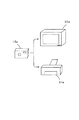
図1は、本発明の一実施形態にかかる画像処理装置を適用した画像処理システムをブロック図により示しており、図2は具体的ハードウェア構成例を概略ブロック図により示している。
図1において、画像入力装置10は単板式のCCDを利用して撮像した実画像などをドットマトリクス状の画素で表した画像データとして画像処理装置20へ出力する。上述した原理から単板式のCCDにて撮像された画像データには色にじみが発生し、画像処理装置20は入力画像データにおいて色にじみ画素を検出して当該色にじみ画素を基準とした所定範囲で色にじみを低減するように画像処理して画像出力装置30へ出力し、画像出力装置30は画像処理された画像データをドットマトリクス状の画素で出力する。
【0051】
画像処理装置20は、色にじみ画素を検出することから色にじみ画素検出手段を備えているし、当該検出された色にじみを基準として色にじみを低減するように画像処理を行うことから画像処理手段をも備えていると言える。
【0052】
画像入力装置10の具体例は図2における単板式のCCDを備えたフィルムスキャナ11やデジタルスチルカメラ12あるいはビデオカメラ14などが該当する。例えば、図3は同デジタルスチルカメラ12の簡単なハードウェア構成例を概略ブロック図により示している。同図において、入射光は光学系12aを介してCCD12bに受光される。このCCD12bはR,G,B各色の色フィルタが各画素に対応して所定の割合で配置されており、駆動回路12cにて各画素における色信号が出力される。出力された色信号はデジタル変換されて補間演算回路12dに入力され、当該補間演算回路12dにて各画素において直接得ることができない要素色成分についての色信号を周辺の画素からの線形補間演算により取得し、RGBの階調データとして画像メモリ12eに保存する。
【0053】
一方、画像処理装置20の具体例はコンピュータ21とハードディスク22とキーボード23とCD−ROMドライブ24とフロッピーディスクドライブ25とモデム26などからなるコンピュータシステムが該当し、画像出力装置30の具体例はプリンタ31やディスプレイ32等が該当する。なお、モデム26については公衆通信回線に接続され、外部のネットワークに同公衆通信回線を介して接続し、ソフトウェアやデータをダウンロードして導入可能となっている。
【0054】
本実施形態においては、画像入力装置10としてのフィルムスキャナ11やデジタルスチルカメラ12が画像データとしてRGBの階調データを出力するとともに、画像出力装置30としてのプリンタ31は階調データとしてCMY(シアン、マゼンダ、イエロー)あるいはこれに黒を加えたCMYKの二値データを入力として必要とするし、ディスプレイ32はRGBの階調データを入力として必要とする。
【0055】
一方、コンピュータ21内ではオペレーティングシステム21aが稼働しており、プリンタ31やディスプレイ32に対応したプリンタドライバ21bやディスプレイドライバ21cが組み込まれている。また、画像処理アプリケーション21dはオペレーティングシステム21aにて処理の実行を制御され、必要に応じてプリンタドライバ21bやディスプレイドライバ21cと連携して所定の画像処理を実行する。従って、画像処理装置20としてのこのコンピュータ21の具体的役割は、RGBの階調データを入力し、色にじみ画素を検出して色にじみを低減するように画像処理を施したRGBの階調データを作成し、ディスプレイドライバ21cを介してディスプレイ32に表示させるとともに、プリンタドライバ21bを介してCMY(あるいはCMYK)の二値データに変換してプリンタ31に印刷させることになる。
【0056】
このように、本実施形態においては、画像の入出力装置の間にコンピュータシステムを組み込んで画像処理を行うようにしているが、必ずしもかかるコンピュータシステムを必要とするわけではなく、単板式のCCDにて撮像されるとともに上述したように補間演算されて色にじみが発生した画像データに対して色にじみを低減するように画像処理を行うシステムに適用可能である。例えば、図4に示すように単板式のCCDを備えたデジタルスチルカメラ13a内に同様に画像処理する画像処理装置を組み込み、色にじみを低減した画像データを用いてディスプレイ32aに表示させたりプリンタ31aに印字させるようなシステムであっても良い。また、図5に示すように、コンピュータシステムを介することなく画像データを入力して印刷するプリンタ31bにおいては、単板式のCCDを有するフィルムスキャナ11bやデジタルスチルカメラ13b等を介して入力される画像データに対して色にじみを低減して画像処理するように構成することも可能である。
【0057】
上述した色にじみ画素の検出と色にじみを低減する画像処理は、具体的には上記コンピュータ21内にて図6などに示すフローチャートに対応した画像処理プログラムで行っている。
本実施形態において採用する色にじみの低減方法は、後述するように平滑化フィルタなどを作用させて行う点については従来と同様であるが、同平滑化フィルタなどを作用させる領域は色にじみ画素の周辺に限られることで従来とは異なる。ここで、処理対象となる画像データについて、図7(a)および(b)に示すように二種類の画像サイズのビットマップを考え、両者に対して図中斜線部分で示す同一サイズの平滑化フィルタを作用させるものとする。画像サイズが異なるとは、画像データの各画素とCCDの各画素が一対一で対応していれば、使用するCCDの画素数に応じて画像サイズも当然に異なるが、同一画素数のCCDを使用した場合であっても適宜伸縮して画像サイズが変更される場合もあり、かかる場合も含むものとする。
【0058】
図からも明らかなように、同一サイズの平滑化フィルタを適用している限りにおいては、画像サイズが異なれば平滑化処理される領域が画像全体に対して占める割合も異なる。従って、あらゆる画像サイズの画像データに対して一律に同一サイズの平滑化フィルタを作用させてしまうと、図7(a)に示すように適当な大きさの領域が平滑化処理されることもあれば、同図(b)に示すように平滑化処理される領域が画像全体に対して占める割合が大きくなってしまうことがある。平滑化処理するということは、画像をぼやけさせることに他ならないから、同図(b)に示すものにおいては画像の大部分がぼやけてしまうことになりかねない。
【0059】
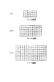
そこで、本実施形態においては、図8に示すようにな3×3、5×5、7×7画素といった複数の異なるサイズの平滑化フィルタを保持しており、画像サイズに応じてこれらの平滑化フィルタを適宜使い分けるようにしている。ここで、ビットマップ画像の画像サイズを判定するにあたっては、画像の(height)×(width)を算出して画素数を求め、この算出された画素数を指標としてもよいが、本実施形態においては、次式で表されるAに従って処理対象画像の画像サイズを判定する。
【0060】
A=min(height,width) …(1)
ここにおいて、min(height,width)はheightとwidthのいずれか小さい方を意味する。そして、ステップS110では、
A<300ならば、
3×3画素の平滑化フィルタ
300≦A≦600ならば、
5×5画素の平滑化フィルタ
A>600ならば、
7×7画素の平滑化フィルタ
というように分岐し、それぞれステップS122〜ステップS126にて用いる平滑化フィルタの種類をワークエリアに保存する。ワークエリアはコンピュータ21内のRAMであってもよいしハードディスク22であってもよい。
【0061】
ここでmin(height,width)を基準としているのは次のような理由による。平滑化フィルタのサイズが適当か否かを判断するにあたっては、本来的には全画素数に対して平滑化処理される画素数の割合で判断すればよい。しかしながら、例えば、同一画素数の画像データであっても図9(a)に示すビットマップ画像のように幅広の画像もあれば、同図(b)に示すビットマップ画像のように高さ方向に比べて幅方向の長さが若干長い標準的な画像もある。仮に、処理対象画像の全画素数に応じて使用する平滑化フィルタを決定するものとすると、両者で同一の平滑化フィルタが選択されることになる。すると、後者においては同平滑化フィルタのサイズが適当であっても、前者においては高さ方向がほぼ全長にわたって平滑化されることがあり、このような場合、視覚的にはぼやけた印象を受ける。従って、heightとwidthのいずれか小さい方を基準とすれば、このような弊害を回避することができる。
【0062】
図6のフローチャートを参照すると、図10に示すようにドットマトリクス状の画素からなる画像データについて処理対象画素を水平方向に主走査しつつ垂直方向に副走査して移動させ、各画素について色にじみ画素であるか否かを判断している。
【0063】
画像データがドットマトリクス状の画素から構成されている場合には、各画素ごとにRGBの階調データ(「0」〜「255」)で表されている。ステップS122〜ステップS126にて使用する平滑化フィルタの種類をワークエリアに保存したら、次なるステップS130においては、対象画素とその周辺画素におけるRおよびBの階調データの差分ΔRBを算出する。このΔRBは、
ΔRB=|R−B| …(2)
と表される。
【0064】
本実施形態におけるCCDは図23(a)に示すように、各画素に対応してR,G,Bの各色の色フィルタがモザイク状に配置されるとともに、Gの色フィルタのみが千鳥状に配置されて密度が高くなっており、RおよびBの色フィルタが低密度となっている。そして、各画素において直接的に得ることができない色信号を隣接する画素の色信号から線形補間演算してR,G,B全色の色信号を得て階調データに変換している。従って、確率からすれば補間演算の結果、ある画素において低密度のR,Bの階調データについて、本来の強度が得られなかったり、本来必要のない色成分が発生するなど偽の要素色成分により色にじみが発生するということができる。
【0065】
また、色にじみは特に白・黒間の境界付近にて顕著に現れることが知られている。例えば、Rの色フィルタに対応する画素において白色を表現する場合、本来のRGBの階調データは(R,G,B)=(255,255,255)となるところ、補間演算の結果(R,G,B)=(255,255,127)となったりする。ここにおいて、Gの色フィルタは高密度であるからG成分については補間演算により偽の要素色成分が発生する確率が小さく、他方、Rの成分は色フィルタから直接的に得ることができるため偽の色成分が発生することはない。本来的にはある画素において白を表現するならばΔRBは「0」となるし、黒を表現する場合もΔRBは「0」となるはずではあるが、色にじみ画素においてはこれに比べてΔRBの値が大きくなる傾向を示す。
【0066】
むろん、画像データによってはもともとRおよびGの成分が高く、Bの成分が低い画素も当然に存在し得る。しかし、このような場合には各要素色成分は隣接画素においても保持され、当該画素から遠ざかるにつれてΔRBの値はなだらかに変化する場合が多い。これに対して、色にじみは原理的に画素単位で発生しつつ、かつ、互いに隣接する画素のいずれか一方が白または黒などの画素であるから、隣接画素間でΔRBの変化度合いが大きい画素を色にじみ画素としてもあながち間違ってはいないといえる。そこで、本実施形態においては、後述するようにして処理対象画素と周辺画素との間でΔRBの値の変化度合いを調べ、同変化度合いが大きい画素を色にじみ画素として検出する。むろん、Gの色フィルタは高密度であるから補間演算により偽の要素色成分が発生する可能性は低いと言えるため、この要素色成分を基準として(2)式を、
ΔGR=|G−R| …(3)
ΔGB=|G−B| …(4)
という式に代替することも可能である。
【0067】
また、このようなΔRBの変化度合いを調べるにあたっては、低密度の色フィルタに対応する画素間で比較する方が好適である。すなわち、高密度の色フィルタに対応する画素と比べて低密度の色フィルタに対応する画素の方が偽の要素色成分が発生しやすいため、低密度の色フィルタに対応する画素間でΔRBの変化度合いを比較する方がより信頼性の高い検出を行うことができる。
【0068】
実際の色にじみ画素の検出はステップS140にて行われ、このステップS140では上記のようにして算出したΔRBの周辺画素間での変化度合いから色にじみ画素か否かの判定を行う。このとき、図11に示すように、処理対象画素を中心とするとともに、水平方向をx、垂直方向をyとしたマトリクスを考え、
E=4ΔRB(x,y)−2ΔRB(x−1,y−1)
−2ΔRB(x+1,y−1) …(5)
で表されるEの値と所定のしきい値Thとの大小関係を比較する。そして、E≧Thの場合に色にじみ画素であると判断する。従って、上述したステップS130においては、判定対象の画素におけるΔRB(x,y)を求めておくとともに、周辺画素のΔRBの値としてΔRB(x−1,y−1)およびΔRB(x+1,y−1)を求めておくことになる。
【0069】
E≧Thの判定基準に従って色にじみ画素を検出する意味は次のようになる。処理対象画素において色にじみが発生していると、当該画素とその周辺画素間のΔRB値の変化度合いが大きくなるため(5)式を参照するとEの値も大きくなり、所定のしきい値Thを越えた場合に色にじみ画素と判断する。また、(5)式および図11を参照すると、判定対象の画素と斜め方向の画素とでΔRBの変化度合いを調べていることが容易に分かる。ここで、図23(a)を参照すれば、判定対象の画素がRに該当すれば斜め方向の画素はBに該当し、判定対象の画素がBに該当すれば斜め方向の画素はRに該当するし、判定対象の画素がGに該当すれば斜め方向の画素はGに該当する。すなわち、判定対象の画素が低密度の要素色に対応する場合は、隣接する低密度の要素色に対応する画素との間でΔRB値の変化度合いを調べ、判定対象の画素が高密度の要素色に対応する場合は、隣接する高密度の要素色に対応する画素との間でΔRBの変化度合いを調べていることになる。
【0070】
従って、ステップS130,S140にて互いに隣接する画素間において低密度の色フィルタに対する要素色強度間の差分の変化度合いに基づいて色にじみ画素を検出しており、これらを実行するハードウェア構成とソフトウェアとによって色にじみ画素検出手段を構成することになる。
【0071】
ステップS140にて色にじみ画素であるものと判断した場合には、ステップS150にて当該画素がエッジ画素か否かを判定する。エッジ画素であるか否かを判断するにあたっては、色差成分に基づいて行う手法が有効であるため、本実施形態においてはRおよびBの階調データから輝度成分Yを減算してそれぞれ色差成分C1,C2を求める。なお、この色差成分C1,C2は、
C1=R−Y …(6)
C2=B−Y …(7)
と表すことができる。
【0072】
しかしながら、RGBの階調データは直接には輝度の値を持っておらず、輝度を求めるためにLuv表色空間に色変換することも可能であるが、演算量などの問題から得策ではない。このため、テレビジョンなどの場合に利用されているRGBから輝度を直に求める次式の変換式を利用する。
Y=0.30R+0.59G+0.11B …(8)
【0073】
エッジ画素は画像の境界部分であるから、隣接する画素間で色差成分C1,C2の変化度合いが大きいといえるため、次の二つの判定基準のうちでいずれか一方を充足する場合にエッジ画素として判断することができる。
|C1(x,y)−C1(x−1,y−1)|≧Th1
…(9)
|C2(x,y)−C2(x−1,y−1)|≧Th2
…(10)
なお、ここにおけるxは水平方向の座標を示しており、yは垂直方向の座標を示している。
【0074】
すなわち、(9)および(10)式の意味するところは、図12に示すように、当該色にじみ画素を中心としたドットマトリクス状の画素からなる画像データにおいて、隣接する斜め方向の画素間で色差成分C1,C2の変化度合いを求め、それぞれしきい値Th1,Th2以上あるか否かを判定していることに他ならない。そして、いずれか一方の判断基準を充足する場合にエッジ画素と判断していることになる。むろん、本来的には画素は図13に示すように縦横に升目状に配置されており、中央の画素に注目すると八つの隣接画素がある。従って、同様にそれぞれの隣接する画素との間で色差成分C1,C2の変化度合いを求めるとともに、それぞれしきい値Th1,Th2との間で比較演算し、いずれか一つの比較演算にて色差成分C1またはC2の変化度合いがしきい値Th1またはTh2以上ある場合に色にじみ画素と判断すればよい。
【0075】
このように色にじみ画素がエッジ画素であるか否かを判断するにあっては、色差成分C1,C2の変化度合いに基づいて行う手法が有効ではあるものの、一つの色にじみ画素について、隣接する八画素のそれぞれにおいて色差成分C1,C2についての比較演算を行わなければならないため、演算量が多大となって処理速度が低下してしまうことになりかねない。そこで、図14に示すように縦横方向の四画素について比較演算を行ったり、あるいは図15に示すように斜め方向の四画素について比較演算を行うようにし、演算量を低減するようにしてもかまわない。
【0076】
また、エッジ画素であるか否かを輝度勾配の大小で判断するようにしてもよく、この場合には上述した(9)および(10)式を次式に代替すればよい。
|Y(x,y)−Y(x−1,y−1)|≧Th3
…(11)
この(11)式をエッジ画素の判断基準として用いれば、(9)および(10)式を用いる場合に比べて演算量が半減されることは容易に分かることである。
【0077】
ステップS150にて当該色にじみ画素がエッジ画素ではないものと判断した場合には、ステップS152で同色にじみ画素に対してステップS122〜ステップS126にて決定した平滑化フィルタを作用させて同色にじみ画素を基準とした所定範囲の画素に対して平滑化処理を行う。むろん、平滑化処理を行うにあたっては、色差成分の平滑化が有効であるため、本実施形態においては上記(6)、(7)式に基づいて算出した色差成分C1,C2に対して平滑化処理を施す。
【0078】
ここで、平滑化フィルタを用いた平滑化処理について説明する。図8に示す各平滑化フィルタにおいて、中央の数値をマトリクス状の画像データにおける処理対象画素の色差成分C1,C2の重み付けとし、その周辺画素に対して同平滑化フィルタの升目における数値に対応した重み付けをして積算するのに利用される。この場合、すべての升目に「1」が立てられているため、平滑後の色差成分C1'は各升目の色差成分C1を合計して全升目数で除算して求め、平滑後の色差成分C2'も同様にして求められる。むろん、各升目に適宜重み付けを持たせるようにしてもかまわない。ただし、平滑化フィルタを作用させるとういことは、上述したようなマトリクス演算を行うことであるから、各升目に重み付けを持たせれば演算量も増加することになる。すなわち、本実施形態においては、平滑化フィルタの各升目に「1」を立てているため、各画素のデータを合計して升目数で除算すればよいが、各升目に重み付けがなされている場合には升目数だけ乗算演算と加算演算が必要になることから演算量が多大となる。
【0079】
従来のように画像データの全画素を対象としてこのようなマトリクス演算を行うと、演算量が膨大となって多大な処理時間がかかってしまうことがある。従って、本実施形態のように色にじみ画素を検出して当該色にじみ画素の周辺について平滑化処理を行うようにすれば、大幅な演算量の削減が期待され、高速な画像処理を実現可能となる。
【0080】
一方、ステップS150で当該色にじみ画素がエッジ画素であると判断した場合には、ステップS154で同色にじみ画素を中心として5×5画素のメジアンフィルタを作用させる。なお、実際に適用するメジアンフィルタのサイズは、必ずしも5×5画素である必要はなく、3×3画素のメジアンフィルタを適用するなど適宜変更可能である。そこで、説明の便宜上、3×3画素のメジアンフィルタを適用する場合について説明する。
【0081】
例えば、図16に示すように、色にじみ画素を中心とした3×3画素のドットマトリクスを考慮する。なお、各升目の値は色差成分C1の値を示しており、図中の斜め線がエッジ方向に相当する。ここで、3×3画素のメジアンフィルタを適用するということは、全九画素の色差成分C1の値を昇順または降順にソートし、中央の値を選択して色にじみ画素の色差成分C1と置き換えることを意味する。すなわち、同図に示すものにおいては、色差成分C1の値が「10」の画素が六画素存在し、「40」の画素が一画素存在し、「100」の画素が三画素存在しているため、これらの値を仮に昇順にソートしたものとすると図17に示すようになる。すると、同図からも明らかなように中央の値は「10」となり、当該色にじみ画素の色差成分C1は「10」となる。
【0082】
一方、ここにおいて3×3画素の平滑化フィルタを作用させたものとすると、升目の合計値「300」を画素数「9」で除算した値である「33」が平滑化処理後の色差成分C1'となる。この平滑処理後の色差成分C1'は色にじみ画素に対して周辺画素の色差成分C1を平均化して加算したものであるから、滑らかな画像データとしていることになる。このようにして滑らかにしたものはいわゆるローパスフィルタをかけたものと同様の意味あいを持ち、画像は滑らかにされて色にじみが目立たなくなるが、エッジ部分もぼやけた印象となってしまうため得策ではない。そこで、エッジ画素に対しては上述したメジアンフィルタを適用すればエッジ部分がぼやけないことは、上記の演算結果からも明らかである。
【0083】
他方、図16を参照すると、色差成分C1の値が「40」の画素にて色にじみが発生していることが分かる。そこで、この色にじみ画素に対して3×3画素のメジアンフィルタを適用すると、隣接する八画素の中で七画素の色差成分の値が「100」であり、一画素のみ色差成分の値が「10」であるため、当該色にじみ画素の色差成分の値も「100」に置き換わることになり、色にじみが低減されることが分かる。このように、メジアンフィルタはエッジ部分をぼやけさせないようにしつつ、色にじみを低減させる効果をも有しており、上記のステップS150にて当該色にじみ画素がエッジ画素であるか否かを判定する意味はかかる事由によるものである。
【0084】
なお、ここで例示したメジアンフィルタは3×3画素であるが、むろん、本実施形態にて採用する5×5画素のメジアンフィルタの場合、全二十五画素の中で中央の値を選択すればよく、3×3画素の場合と全く同様に考えることができる。また、色差成分C1について例示したが、色差成分C2についても同様であることはいうまでもない。
【0085】
ところで、平滑化フィルタとメジアンフィルタの演算速度を比べると、メジアンフィルタの方が比較的遅いため、メジアンフィルタを適用する場面は可能な限り抑えた方が処理速度上からも好適である。エッジ画素の判断基準として(9)および(10)式を採用する場合、色差成分C1,C2のいずれか一方で同式を充足する場合もあれば、色差成分C1,C2の双方で同式を充足する場合もありうる。ここで、前者の場合において、双方の色差成分についてメジアンフィルタを適用する必要性はないし、処理速度の低下を招くことから、同式を充足する色差成分においてのみステップS154でメジアンフィルタを適用し、別の一方の色差成分についてはステップS152で平滑化フィルタを適用すれば処理速度を全体として向上させることができる。むろん、エッジ画素の判断基準として(11)式を採用する場合には、いずれの色差成分の変化度合いが大きいかといったことは判断し得ないため、この場合にはステップS154で色差成分C1,C2の双方に対してメジアンフィルタを適用することになる。
【0086】
上述したように、色にじみを低減するということは、画像を滑らかにして色にじみを目立たなくすることに他ならず、その部分がぼやけた印象となってしまうことも想定しうる。そこで、本実施形態においては、次なるステップS160にてエッジ強調処理を行う。
【0087】
このエッジ強調処理は、強調前の各画素の輝度Yに対して強調後の輝度Y'が
Y'=Y+(Y−Yunsharp) …(12)
として演算される。ここで、Yunsharp は色にじみ画素の画像データに対してアンシャープマスク処理を施したものであり、次にアンシャープマスク処理について説明する。本実施形態においては、図18に示すように3×3、5×5、7×7画素からなる三種類のアンシャープマスクを備えており、それぞれステップS122〜S126で決定した平滑化フィルタのサイズに対応している。例えば、3×3画素の平滑化フィルタを選択したら、3×3画素のアンシャープマスクを選択することになる。これらのアンシャープマスクも上述した平滑化フィルタと同様に、中央の数値を各画素におけるY(x,y)の重み付けとし、その周辺画素に対して同マスクの升目における数値に対応した重み付けをして積算するのに利用される。例えば、3×3画素のアンシャープマスクを使用する場合、
【0088】
【数1】

【0089】
Yunsharp (x,y)は色にじみ画素に対して周辺画素の重み付けを低くして加算したものであるから、この場合も同様にローパスフィルタをかけたものと同じ意味あいを持つ。従って、「Y(x,y)−Yunsharp (x,y)」とは本来の全成分から低周波成分を引いたことになってハイパスフィルタをかけたものと同様の意味あいを持つ。そして、ハイパスフィルタを通過したこの高周波成分を「Y(x,y)」に加えれば高周波成分を増したことになり、エッジが強調される結果となって画像のシャープさが向上する。
【0090】
なお、これらのアンシャープマスクは図18からも明らかなように、中央部にて最も重み付けが大きく、周縁に向かうにつれて徐々に重み付け係数が小さくなっている。従って、周縁側の重み付け係数が升目の合計値に与える影響はわずかであるといえる。一方、(13)式等で示されるマトリクス演算は、処理対象画素の周囲の画素に対して、採用するアンシャープマスクの升目数だけ乗算演算と加算演算が必要になることから演算量が多大となることも観念される。そこで、本実施形態においては、予め周縁側の重み付け係数を省いて構成した3×3、5×5、7×7画素のアンシャープマスクを使用することにより演算量を削減して処理速度を高めるようにしている。
【0091】
ところで、本実施形態においては、平滑化フィルタのサイズとアンシャープマスクのサイズを同一としているが、これは次のような理由による。例えば、図19で示すビットマップ画像に図中斜線部分で示す領域に対して平滑化処理を行い、図中波線部分で示す領域に対してアンシャープマスク処理を行って輝度を強調したものとする。上述したように輝度を強調する意味は、平滑化処理されて失われたシャープさを補償するものであるから、平滑化領域の外側まで輝度を強調してしまうと、この外側の領域において不自然にシャープさが向上してしまうことが発生し得る。このため、本実施形態では平滑化フィルタとアンシャープマスクを同一サイズとしているが、むろん、前者に比べて後者のサイズが小さくなるようにしてもかまわない。
【0092】
ステップS160では上記のようなエッジ強調処理を行うとともに、強調後の輝度Y'と処理後の色差成分を用いつつ(6)〜(8)式に基づいてR',G',B'の階調データを得る。すなわち、ステップS152,S154にて色にじみを低減するとともに、ステップS160にて階調データを生成しており、これらを実行するハードウェア構成とソフトウェアとによって画像処理手段を構成することになる。
【0093】
なお、ステップS160において、強調した輝度Y'を使用することからR',G',B'の階調データが負の値となったり、「255」を越えるような値となることがある。しかし、階調幅としては、「0」〜「255」の範囲であるため、負の階調データは一律に「0」とし、「255」を越える階調データは一律に「255」とする。そして、次のステップS170にて処理対象画素を移動させ、ステップS180にて全画素について終了したと判断するまで同様の処理を繰り返す。
【0094】
ところで、色にじみ画素を中心として平滑化フィルタを適用し、その後にエッジ強調処理を行えば、平滑化処理によって色にじみが低減され、エッジ強調処理によって平滑化処理で失われた画像のシャープさが補償される。従って、本来的には色にじみ画素がエッジ画素であるか否かを問わず、全ての色にじみ画素に対して一律にかかる処理を実行すればよく、このような構成としても効果を得ることができる。しかし、かかる構成においては、経験的な見地からエッジ部分がぼやけてしまうことがあったため、色にじみ画素がエッジ画素である場合にメジアンフィルタを適用したところ良好な結果を得ることができた。
【0095】
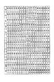
ここで、本実施形態の平滑化処理およびエッジ強調処理の効果について、簡単な一次元のシミュレーションモデルを例示しつつ説明する。
図20は、エッジ強調処理を行わない場合の一次元シミュレーションモデルにおいて各種のパラメータの値を示す表である。同図において、左端のR,G,BのマトリクスはCCDの色フィルタ配列を示している。このマトリクスの右隣に示す「IN」は光の入射状況を示しており、「1(階調データは255)」ならば光があたっている、すなわち「白」を意味し、「0(階調データは0)」ならば「黒」を意味する。そして、CCDの各画素において、直接得ることができない色信号は隣接する画素の色信号から線形補間演算により得ているものとする。
【0096】
ここで、本来二次元の配列で考察するべきではあるが、説明を簡略化するため、上記R,G,Bのマトリクスの中央縦列に着目する。この意味において、一次元のシミュレーションモデルという。すると、上述した原理から白・黒の境界付近にそれぞれG(B)=0.5、R=0.5というように偽の色信号が発生し、この偽の色信号が発生した画素が色にじみ画素として検出される。色にじみ画素が検出されると、(6)〜(8)式に従って色差成分C1およびC2が算出され、この色差成分C1,C2が平滑化処理されて色差成分C1',C2'が得られる。なお、ここでは一次元の平滑化フィルタとして「1,1,1,1,1,1,1」を適用している。すなわち、処理対象画素の前後それぞれの三画素の画素値を合計して「7」で除算する。そして、得られた色差信号C1',C2'を(6)〜(8)式に基づいて元の色信号に戻し、平滑処理後のR',G',B'が得られる。図からも明らかなように白・黒の境界付近の画素における(R',G',B')はそれぞれ(0.75,0.61,0.61)と、(0.25,0.11,0.11)となり、本来の「IN」の値に近づいて色にじみが低減されたことがわかる。
【0097】
また、図21は、平滑化処理を行うとともに、平滑化フィルタと同一サイズのアンシャープマスクを用いてエッジ強調処理を行った場合の一次元シミュレーションモデルを同様に示している。この場合も色差成分C1,C2を求めて平滑化処理を行うことは上述したものと相違はないが、(6)〜(8)式を用いて元の色信号に戻す際に、「1,6,18,25,18,6,1」の重み付けを持たせた一次元のアンシャープマスクを利用して強調処理した輝度信号Y'を使用する。すると、白・黒の境界付近の画素における(R',G',B')はそれぞれ(0.81,0.67,0.67)と、(0.10,−0.04,−0.04)となる。むろん、RGBの信号値としてとり得る値は「0」〜「1」であるからから実際には後者のデータは(0.10,0,0)となり、図20に示すものに比べて色にじみがさらに解消されたことがわかる。
【0098】
さらに、図22は、平滑化フィルタよりも小さいサイズのアンシャープマスクを用いてエッジ強調処理を行った場合の一次元シミュレーションモデルを同様に示している。この場合、一次元の「1,11,25,11,1」という平滑化フィルタのサイズ(7桁)よりも小さい5桁のアンシャープマスクを使用している。そして、上述したものと同様にして演算を行うと、白・黒の境界付近の画素における(R',G',B')はそれぞれ(0.79,0.65,0.65)と、(0.10,−0.04,−0.04)となる。このように、図21に示すものに比べれば、色にじみの解消程度は劣るものの、図20に示すものに比べれば色にじみがさらに解消されていることがわかる。
【0099】
次に、上記構成からなる本実施形態の動作を説明する。
単板式のCCDを有するデジタルスチルカメラ12で撮像した実画像をコンピュータ21に取り込んで、プリンタ31にて印刷する場合を想定する。すると、まず、コンピュータ21にてオペレーティングシステム21aが稼働しているもとで、画像処理アプリケーション21dを起動させ、デジタルスチルカメラ12から画像データを取り込む。画像データが同オペレーティングシステム21aを介して画像処理アプリケーション21dに取り込まれたら、ステップS110にて(1)式に基づいて画像のサイズを判定するための指標値を取得するとともに、この指標値と所定のしきい値とを比較し、ステップS122〜ステップS126にて使用する平滑化フィルタおよびアンシャープマスクのサイズを決定してワークエリアに保存する。
【0100】
そして、ステップS130にて処理対象画素を初期位置に設定し、(2)式に従って当該画素とその周辺画素におけるΔRBの値を算出する。その後、ステップS140にて(5)式に基づいて処理対象画素とその周辺画素との間で同ΔRBの値の変化度合いを調べ、所定のしきい値Thと比較して同変化度合いが大きい場合に色にじみ画素と判断する。
【0101】
色にじみ画素と判断されたら、ステップS150にて(6)〜(8)式に基づいて処理対象画素およびその周辺画素について色差成分C1,C2を算出し、(9)および(10)式、あるいは(11)式などの判定基準に従って当該色にじみ画素がエッジ画素であるか否かを判断する。ここで、エッジ画素ではないものと判断した場合には、ステップS152でステップS122〜ステップS126にてワークエリアに保存しておいたフィルタサイズに等しい平滑化フィルタを作用させる。すなわち、色差成分C1,C2のそれぞれにつき、平滑化フィルタの升目に対応する画素の色差成分を合計して升目数で除算することにより平滑化処理された色差成分C1',C2'を得る。
【0102】
一方、ステップS150にて当該色にじみ画素がエッジ画素であると判断した場合には、ステップS154で同色にじみ画素を中心とした5×5画素のメジアンフィルタを作用させる。すなわち、色にじみ画素を中心とした全二十五画素の色差成分の値を昇順または降順にソートし、中央の値を選択して色にじみ画素の色差成分と置き換える。このとき、ステップS150にて(9)および(10)式の判定基準を採用した場合には、色差成分C1,C2のそれぞれにて同式を充足する色差成分についてステップS154でメジアンフィルタを適用し、同式を充足しない色差成分についてはステップS152で上記の平滑化フィルタを適用する。むろん、ここにおいて双方の色差成分について同式を充足する場合にはステップS154で色差成分C1,C2の双方についてメジアンフィルタを適用する。他方、ステップS150にて(11)式の判定基準を採用する場合には、ステップS154で色差成分C1,C2の双方に対してメジアンフィルタを適用することになる。
【0103】
その後、ステップS160にてステップS122〜S126で決定したサイズのアンシャープマスクを使用して処理対象画素およびその周辺画素について輝度成分Yの低周波成分Yunsharp を求めるとともに、元の輝度成分Yから同低周波成分Yunsharp を減算することにより高周波成分を求め、同元の輝度成分Yに当該高周波成分を加算して強調後の輝度成分Y'を得る。具体的には、(13)式などに基づいて演算を行うことになる。そして、この強調後の輝度成分Y'と処理後の色差成分を用いつつ、(6)〜(8)式に基づいて平滑処理後のR',G',B'の階調データを得る。以上の処理をステップS170にて処理対象画素を移動させながらステップS180にて全画素について実行したと判断するまで繰り返す。
【0104】
全画素について実行し終えたら、画像処理された画像データをディスプレイドライバ21cを介してディスプレイ32に表示し、良好であればプリンタドライバ21bを介してプリンタ31にて印刷させる。すなわち、同プリンタドライバ21bは色にじみが低減されたRGBの階調データを入力し、所定の解像度変換を経てプリンタ31の印字ヘッド領域に対応したラスタライズを行なうとともに、ラスタライズデータをRGBからCMYKへ色変換し、その後でCMYKの階調データから二値データへ変換してプリンタ31へ出力する。
【0105】
以上の処理により、デジタルスチルカメラ12から取り込んだ実画像データは自動的に色にじみが発生している部分のみ色にじみを低減するように画像処理されてディスプレイ32に表示された後、プリンタ31にて印刷される。すなわち、色にじみが発生している部分のみ色にじみを低減するように画像処理するため、演算量を削減して高速な画像処理を実現することができる。
【0106】
このように、画像処理の中枢をなすコンピュータ21はステップS130,S140にて低密度の要素色強度に基づいて処理対象画素が色にじみ画素か否かを判定するとともに、色にじみ画素と判定した場合にステップS150にてエッジ画素であるか否かを判断し、エッジ画素でない場合にはステップS152にて平滑化フィルタを作用させ、他方、エッジ画素である場合にはステップS154にてメジアンフィルタを作用させることにより、色にじみを低減すべく画像処理するようにしたため、演算量を削減して高速な画像処理を実行することができる。
【図面の簡単な説明】
【図1】 本発明の一実施形態にかかる画像処理装置を適用した画像処理システムのブロック図である。
【図2】 同画像処理装置の具体的ハードウェアのブロック図である。
【図3】 デジタルスチルカメラの簡単なハードウェア構成例を示すブロック図である。
【図4】 本発明の画像処理装置の他の適用例を示す概略ブロック図である。
【図5】 本発明の画像処理装置の他の適用例を示す概略ブロック図である。
【図6】 本発明の画像処理装置における色にじみ画素の判定と画像処理部分を示すフローチャートである。
【図7】 画像サイズと平滑化領域との関係を示す図である。
【図8】 3×3、5×5および7×7画素の平滑化フィルタである。
【図9】 同一画素数の画像データにおいてheightとwidthの関係を示す図である。
【図10】 処理対象画素を移動させていく状態を示す図である。
【図11】 要素色成分の変化度合いを斜め方向の隣接画素における差分値で求める場合の説明図である。
【図12】 画像の変化度合いを斜め方向の隣接画素における差分値で求める場合の説明図である。
【図13】 隣接する全画素間で画像の変化度合いを求める場合の説明図である。
【図14】 隣接する画素間で画像の変化度合いを求める変形例の説明図である。
【図15】 隣接する画素間で画像の変化度合いを求める別の変形例の説明図である。
【図16】 色にじみ画素を含むエッジ部分の画像データにおいて各画素の色差成分値の一例を示す図である。
【図17】 メジアンフィルタによる演算処理の一例を説明するための図である。
【図18】 3×3、5×5および7×7画素のアンシャープマスクである。
【図19】 平滑化領域とエッジ強調領域との関係を示す図である。
【図20】 エッジ強調処理を行わない場合の一次元シミュレーションモデルにおける各種パラメータの値を示す表である。
【図21】 平滑化フィルタと同一サイズのアンシャープマスクを用いてエッジ強調処理を行った場合の一次元シミュレーションモデルにおける各種パラメータの値を示す表である。
【図22】 平滑化フィルタよりも小さいサイズのアンシャープマスクを用いてエッジ強調処理を行った場合の一次元シミュレーションモデルにおける各種パラメータの値を示す表である。
【図23】 色にじみの発生原理を説明するための図である。
【符号の説明】
10…画像入力装置
20…画像処理装置
21…コンピュータ
21a…オペレーティングシステム
21b…プリンタドライバ
21c…ディスプレイドライバ
21d…画像処理アプリケーション
22…ハードディスク
23…キーボード
24…CD−ROMドライブ
25…フロッピーディスクドライブ
26…モデム
30…画像出力装置[0001]
BACKGROUND OF THE INVENTION
Image data captured using a single-plate solid-state image sensoretcThe present invention relates to an image processing apparatus, an image processing method, and a medium on which an image processing control program is recorded.
[0002]
[Prior art]
In a digital still camera or the like using a solid-state image sensor, a single plate method is often adopted. In this single-plate method, as shown in FIG. 23A, the color filters of R, G, B (red, green, blue) corresponding to each pixel of the solid-state image sensor have a mosaic shape at a predetermined ratio. In particular, the G color filter is arranged in a staggered manner, and the component ratio is high. Therefore, in each pixel of the solid-state imaging device, only one color signal of R, G, B can be obtained, and a color signal of each color cannot be obtained. Therefore, a color signal that cannot be obtained directly in each pixel is interpolated from the color signals of adjacent pixels to obtain color signals of all R, G, and B colors, converted into gradation data, and output. It is displayed on the display based on the gradation data.
[0003]
For example, in FIG. 23A, attention is focused on the middle color filter indicated by an arrow (→). Then, as shown in FIG. 5B, it is assumed that the left half of the center is exposed to light (white portion) and the right half of the center is not exposed to light (black portion). Here, assuming that the color signal level of each color in a state where light is shining is “1” and the same color signal level in a state where no light is shining is “0”, the color signal levels of R and G are essentially the same. The value should be as shown in FIG.
[0004]
However, as described above, the G color signal cannot be obtained directly from the R color filter, and the R color signal cannot be obtained directly from the G color filter. The G color signal of the corresponding pixel is obtained by linear interpolation of the G color signal in the adjacent pixel. On the other hand, the R color signal of the pixel corresponding to the G color filter is obtained by linear interpolation of the R color signal of the adjacent pixel. Then, the G and R color signal levels in each pixel have values shown in FIGS. 23 (d) and 23 (e), respectively. As is apparent from the figure, a false color signal is generated in the pixel near the boundary between the area that is exposed to light and the area that is not exposed to light, and this false color signal causes color blur on the image.(Sometimes called false color)Will occur. In particular, it is known that this color blur appears prominently at the boundary between gray and white. Therefore, in order to reduce such color blur, a smoothing filter (low-pass filter) is applied to the color difference data of all the pixels constituting the image data to make the color blur inconspicuous.
[0005]
[Problems to be solved by the invention]
The conventional techniques described above have the following problems.
Applying a smoothing filter corresponds to distributing the color component of one pixel to surrounding pixels, and performs a matrix operation such as 5 × 5 pixels around the pixel. For example, when performing a matrix operation of 5 × 5 pixels, 5 × 5 = 25 operations are performed per pixel. Therefore, when all the pixels are targeted, the amount of calculation is 25 × the number of pixels, and the processing time may be long.
On the other hand, when the above smoothing process is performed, the image tends to be blurred. In particular, when a color blur pixel is generated at an edge portion that is a boundary portion of an image, the image of the edge portion may be blurred.
[0006]
The present invention has been made in view of the above problems,In reducing the color blur in the image data, the image of the edge portion is prevented from being blurred, andAn object of the present invention is to provide an image processing apparatus capable of shortening the processing time, an image processing method, and a medium recording an image processing control program.
[0007]
[Means for Solving the Problems]
In order to achieve the above object, the invention according to claim 1Complementary element color gradation value data lacking in each pixel of the original image data obtained by imaging with a single-plate solid-state image sensor in which color filters of multiple element colors are arranged in a mosaic pattern An image processing apparatus that performs image processing on generated image data including a plurality of pixels,Color blur pixel detecting means for detecting a color blur pixel included in image data, means for determining whether or not the detected color blur pixel is an edge pixel, and changing the calculation method according to the determination result Image processing means for executing image processing for reducing color blur.
[0008]
In the invention according to
[0009]
As a more specific configuration, the invention according to
[0010]
The sharpness lost by the smoothing process can be compensated by performing the above-described smoothing process on a predetermined range of pixels based on the color blur pixel and then performing the above-described edge enhancement process. However, from an empirical point of view, when a color blur pixel is generated at an edge portion that is a boundary portion of an image, the image of the edge portion may be blurred.
[0011]
That is, when a color blur pixel is detected, it is determined whether or not the color blur pixel is an edge pixel. Here, when it is determined that the pixel is an edge pixel, the image processing unit detects a color difference component for a predetermined range of pixels with reference to the color blur pixel as described above, and among them, the center of the color difference component is detected. The color difference component having a value is replaced with the color difference component of the pixel that blurs the color, and then returned to the original element color component. On the other hand, if it is determined that the pixel is not an edge pixel, the color difference component of the pixels in a predetermined range based on the color blur pixel is smoothed as described above, and then returned to the original element color component.
[0012]
For example, if a color bleed pixel occurs at the boundary between white and black, the color bleed pixel is eliminated because the chrominance component of the color bleed pixel is replaced with the color difference component of the surrounding pixels to become a pure white or black pixel. However, the boundary is not blurred. Further, in determining whether or not the pixel is an edge pixel, since the degree of change of the color difference component between adjacent pixels in the edge pixel increases, the degree of change of the color difference component is compared with a predetermined threshold value, What is necessary is just to judge that it is an edge pixel, when the change degree of the same color difference component is larger. Of course, the edge pixel may be regarded as a pixel having a large luminance gradient, and the edge pixel may be determined based on the degree of change in the luminance component between adjacent pixels.
[0013]
Note that a specific median filter or the like may be applied as a specific configuration for selecting the central value in the color difference component for a predetermined range of pixels.
[0014]
On the other hand, various methods can be adopted for detecting a color blur pixel. As an example, the invention according to
0015]
0016]
For example, image data subject to image processing isConsists of dot-matrix pixels imaged with a single-plate solid-state image sensorCaseIn a single-chip solid-state imaging device, color filters of a plurality of element colors are arranged in a mosaic pattern with a non-uniform density, so that they are supplemented by calculation so as to obtain a uniform density. In this case, a false color component is generated and color bleeding occurs. The color bleed pixel detecting means detects a color bleed pixel in which such color bleed has occurred, and the image processing means performs color bleed for a predetermined range of pixels based on the detected color bleed pixel. Image processing is performed to reduce the image.
0017]
When detecting the presence or absence of color blur for a certain pixel, it is not possible to detect the presence or absence of color blur from the element color components of that pixel in a uniform manner. become. In addition, the occurrence of color blur is caused by the false element color component as described above, and the false element color component is because the color filters of each element color are arranged at a non-uniform density in the solid-state imaging device. It can be said that the element color components for the low density color filter are likely to occur.
0018]
there,Paying attention to the element color intensity (gradation value, etc.) for the low-density color filter between the pixel to be detected and the pixel adjacent to the pixel, the degree of change in this element color intensityBased on the above, a color blur pixel can be detected.
0019]
Here, as an example of a specific method for detecting a color blur pixel,4The present invention relates to the above-mentioned claim.3In the image processing apparatus described in the above item, the color blur pixel detection unit includes:Configuration for obtaining difference data between low-density element colors and other element colors in the original image data when obtaining difference data of gradation values between different element colors for each pixelIt is as.
0020]
Claims configured as above4In the present invention, the color blur pixel detecting means isFind difference data between the low-density element color and other element colors in the original image data,Degree of change of the difference dataOn the basis of theColor blur pixels are detected.
0021]
For example, when it is known in advance that the R and G color filters are alternately arranged as shown in the middle line of FIG. 23A, the low-density color filter is R. G is adopted as a component, and the degree of change in the difference ΔRG = | RG | between the two is examined between adjacent pixels. Then, the value of ΔRG is as shown in FIG. 23 (f). When attention is paid to the degree of change in ΔRG between adjacent pixels, “0” is obtained in the pixels near the boundary between the area where light is applied and the area where light is not applied. .5 ", and such a pixel is detected as a color blur pixel.
0022]
It is not necessary to be limited to the above-described method for detecting a color blur pixel based on the change degree of the difference in element color intensity.5The invention according to claim4In the image processing apparatus described in the
0023]
Claims configured as above5In the invention according to the present invention, there are a plurality of low density color filters.If you want toThe color blur pixel detecting means isFind the difference in gradation value data for each low density element color between adjacent pixels,The color blur pixel is detected based on the change degree of the difference.
0024]
That is, as described above, since the false element color component appears conspicuously for the element color for the low density color filter, attention is paid to the difference in element color intensity for the low density color filter. For example, as shown in FIG. 23A, when the density of the G color filter is high and the density of the R and B color filters is low as a whole, false element color components appear prominently in R and B. It will be. Here, similarly, it is assumed that the middle line is focused, and the B color signal level in each pixel of the middle line is linearly interpolated from the B color filter adjacent to the upper line side. Then, the B color signal level in each pixel in the middle stage line is the same as that shown in FIG. 4D, and the difference between the R and B color signal levels is ΔRB = | RB− = ΔRG. Accordingly, since the value of ΔRB between adjacent pixels is also as shown in FIG. 5F, the degree of change of the same ΔRB is “0.5” in the pixels near the boundary between the area that is exposed to light and the area that is not exposed to light. Thus, such a pixel is detected as a color blur pixel.
0025]
Regardless of whether the focus is on the degree of change in the difference between the reference element color intensity and the low-density element color intensity or on the degree of change in the difference between the low-density element color intensities, Various modes can be considered for checking the degree of change. For example, the degree of change may be examined between pixels adjacent to the eight directions of the horizontal direction, the vertical direction, and the diagonal direction, and the amount of calculation can be reduced by appropriately reducing the comparison direction. For the reasons described above, it can be said that there is a high possibility that a false element color component is generated in a pixel for a low-density color filter. Is preferred. Therefore, the claim6According to another aspect of the invention, in the image processing device according to any one of
0026]
Claims configured as above6In the invention according to the above aspect, the color bleed pixel detecting means has the adjacent low density.Element colorCorresponding pixelBetweenA color blur pixel is detected by checking the degree of change.
0027]
Further, since the sharpness of the image may be lost due to the smoothing process, the image processing means is configured to perform an edge enhancement process.May be.
0028]
Configured as aboveIfThe image processing means performs edge enhancement processing on the image data to compensate for the sharpness lost in the smoothing processing.
0029]
In this way, even if the edge enhancement process is performed, it is considered that if the edge enhancement is performed to the area where the smoothing process is not performed, the outside of the area subjected to the smoothing process is unnaturally edge enhanced. The image processing means may be configured to perform edge enhancement processing on pixels within a range where the smoothing processing is performed.
0030]
Configured as aboveIn this case, the image processing meansEdge enhancement processing is performed on the pixels within the range where the above-described smoothing processing that tends to lose sharpness is performed.
0031]
By the way, in performing the smoothing process, it is not a good idea to uniformly perform the smoothing process in the same range on all the image data. For example, it is assumed that smoothing processing in the same range is performed on both image data having a large image size and image data having a small image size. In this case, since the ratio of the smoothing process in the former to the image is different from the ratio in the latter, even if good results are obtained in the former, the whole may be too blurry in the latter. obtain. Therefore, the image processing means performs a smoothing process on a predetermined range of pixels based on the detected color blur pixels, and performs the smoothing process when the size of the image to be processed is large. And when the size of the same image is small,May be.
0032]
When configured as described above, the image processing means detects the size of image data to be subjected to image processing in advance, and if the size of the image data is large, the range for smoothing processing is increased. If the size is small, the smoothing range is reduced. Specifically, a plurality of smoothing filters having different sizes are held, and the smoothing filter is changed according to the image size. This can be achieved by using different types of ruta.is there.
[0033]
The method of changing the calculation method depending on whether or not the color blur pixel is an edge pixel is not necessarily limited to a substantial device, and as an example, the invention according to claim 7 includes:Complementary element color gradation value data lacking in each pixel of the original image data obtained by imaging with a single-plate solid-state image sensor in which color filters of multiple element colors are arranged in a mosaic pattern An image processing method for performing image processing on generated image data consisting of a plurality of pixels,Image processing is performed to detect a color blur pixel included in image data, determine whether the detected color blur pixel is an edge pixel, and change the calculation method according to the determination result to reduce color blur. It is configured to execute.
0034]
That is, it is not necessarily limited to a substantial apparatus, and there is no difference that the method is also effective.
0035]
By the way, as described above, there may be an image processing apparatus that detects a color blur pixel and reduces color blur for a predetermined range of pixels based on the color blur pixel, or is incorporated in a certain device. The idea of the invention includes various aspects such as being used in a state. Further, it can be changed as appropriate, for example, by hardware or by software.
[0036]
In the case of software for controlling an image processing apparatus as an embodiment of the idea of the invention, it naturally exists on a recording medium on which such software is recorded, and it must be used. As an example, the invention according to
0037]
Of course, the recording medium may be a magnetic recording medium, a magneto-optical recording medium, or any recording medium that will be developed in the future. In addition, the duplication stages such as the primary duplication product and the secondary duplication product are equivalent without any question.
0038]
Further, even when a part is software and a part is realized by hardware, there is nothing completely different in the idea of the invention, and a part is stored on a recording medium, and it is appropriately changed as necessary. It may be in the form of being read.
[0039]
【The invention's effect】
As described above, according to the present invention, it is possible to prevent the edge from being blurred by changing the calculation method depending on whether or not the color blur pixel is an edge pixel.
[0040]
As an example, according to the invention according to
[0041]
And claimsAccording to the invention according to No. 3, since the color blur pixel is detected by a relatively simple calculation method and the color blur is reduced for a predetermined range of pixels based on the color blur pixel, the calculation amount is reduced. And providing an image processing apparatus capable of shortening the processing timebe able to.
[0042]
And claimsAccording to the invention according to No. 4, since it is only necessary to focus on low-density element colors, it is possible to easily detect a color blur pixel.be able to.
[0043]
In other words, it is only necessary to examine the degree of change in the difference between low-density element colors and other element colors, so that color blur pixels can be detected.Calculation can be performed easily.
[0044]
And claimsAccording to the fifth aspect of the present invention, when there are a plurality of low-density element colors, it is only necessary to pay attention to the degree of change in the difference between the low-density element colors.I can.
[0045]
And claimsAccording to the sixth aspect of the invention, since the change degree of the difference is examined with respect to low density element color pixels, detection with higher reliability can be performed.
[0046]
further,Even if the color blur is reduced by the smoothing process, it is only necessary to smooth the color difference component and return it to the original element color component.It can be carried out.
[0047]
further,If edge enhancement processing is performed, the reduction in image sharpness due to smoothing processing is compensated.be able to.
[0048]
Furthermore, if the edge enhancement processing is performed on the pixels within the range to be smoothed, sharpness does not increase unnaturally for pixels outside the range of the smoothing processing.
Further, if the range to be smoothed is changed according to the size of the image to be processed, the smoothing process in the optimum range can be performed.
In addition, the central value is used for the color blur pixel in the color difference component of the pixel in the predetermined range.Thus, color bleeding can be reduced.
[0049]
And claimsAccording to the seventh aspect of the invention, it is possible to provide an image processing method in which edges are not blurred in the same manner.According to the invention, a medium on which an image processing control program is recorded can be provided.
[0050]
DETAILED DESCRIPTION OF THE INVENTION
Hereinafter, embodiments of the present invention will be described with reference to the drawings.
FIG. 1 is a block diagram illustrating an image processing system to which an image processing apparatus according to an embodiment of the present invention is applied. FIG. 2 is a schematic block diagram illustrating a specific hardware configuration example.
In FIG. 1, an
[0051]
The
[0052]
A specific example of the
[0053]
On the other hand, a specific example of the
[0054]
In this embodiment, the
[0055]
On the other hand, an
[0056]
As described above, in this embodiment, a computer system is incorporated between image input / output devices to perform image processing. However, such a computer system is not necessarily required, and a single-plate CCD is used. As described above, the present invention can be applied to a system that performs image processing so as to reduce color blur for image data that has undergone interpolation calculation as described above and has color blur. For example, as shown in FIG. 4, an image processing device that performs image processing in the same manner is incorporated into a digital
[0057]
The above-described image processing for detecting a color blur pixel and reducing the color blur is specifically performed by the image processing program corresponding to the flowchart shown in FIG.
The color blur reduction method employed in the present embodiment is the same as the conventional method in that a smoothing filter or the like is applied as described later, but the region in which the smoothing filter or the like is applied is the color blur pixel. It is different from the conventional one by being limited to the periphery. Here, regarding the image data to be processed, two types of image size bitmaps are considered as shown in FIGS. 7A and 7B, and smoothing of the same size indicated by the hatched portion in the figure is performed for both. Let the filter act. The image size is different. If each pixel of the image data and each pixel of the CCD have a one-to-one correspondence, the image size naturally varies depending on the number of pixels of the CCD used. Even when used, the image size may be changed by appropriately expanding and contracting, and such a case is also included.
[0058]
As is apparent from the figure, as long as smoothing filters of the same size are applied, the proportion of the area to be smoothed with respect to the entire image varies depending on the image size. Accordingly, if a smoothing filter of the same size is uniformly applied to image data of all image sizes, an area of an appropriate size may be smoothed as shown in FIG. For example, as shown in FIG. 5B, the ratio of the area to be smoothed to the entire image may increase. Since the smoothing process is nothing but blurring of the image, most of the image may be blurred in the case shown in FIG.
[0059]
Therefore, in the present embodiment, a plurality of smoothing filters having different sizes such as 3 × 3, 5 × 5, and 7 × 7 pixels as shown in FIG. 8 are held, and these smoothing filters are retained according to the image size. The appropriate filter is properly used. Here, in determining the image size of the bitmap image, (height) × (width) of the image is calculated to obtain the number of pixels, and the calculated number of pixels may be used as an index. Determines the image size of the processing target image according to A expressed by the following equation.
[0060]
A = min (height, width) (1)
Here, min (height, width) means the smaller of height and width. In step S110,
If A <300,
3 × 3 pixel smoothing filter
If 300 ≦ A ≦ 600,
5 × 5 pixel smoothing filter
If A> 600,
7 × 7 pixel smoothing filter
The type of smoothing filter used in steps S122 to S126 is stored in the work area. The work area may be the RAM in the
[0061]
Here, the reason for using min (height, width) as a reference is as follows. In determining whether or not the size of the smoothing filter is appropriate, it may be determined based on the ratio of the number of pixels to be smoothed with respect to the total number of pixels. However, for example, even if the image data has the same number of pixels, there is a wide image like the bitmap image shown in FIG. 9A, but the height direction like the bitmap image shown in FIG. Some standard images have a slightly longer width in the width direction. If the smoothing filter to be used is determined according to the total number of pixels of the processing target image, the same smoothing filter is selected for both. Then, in the latter case, even if the size of the smoothing filter is appropriate, in the former case, the height direction may be smoothed over almost the entire length. In such a case, a visually blurred impression is received. . Therefore, if the smaller one of height and width is used as a reference, such an adverse effect can be avoided.
[0062]
Referring to the flowchart of FIG. 6, as shown in FIG. 10, the pixel to be processed is moved by sub-scanning in the vertical direction while main-scanning the pixel to be processed in the image data including dot matrix pixels, and each pixel is blurred. It is determined whether or not it is a pixel.
[0063]
When the image data is composed of dot-matrix pixels, each pixel is represented by RGB gradation data (“0” to “255”). After the type of the smoothing filter used in step S122 to step S126 is stored in the work area, in the next step S130, a difference ΔRB between the R and B gradation data in the target pixel and its surrounding pixels is calculated. This ΔRB is
ΔRB = | R−B | (2)
It is expressed.
[0064]
As shown in FIG. 23A, in the CCD according to the present embodiment, R, G, and B color filters are arranged in a mosaic pattern corresponding to each pixel, and only the G color filters are staggered. The density is high due to the arrangement, and the R and B color filters are low density. A color signal that cannot be obtained directly in each pixel is linearly interpolated from the color signals of adjacent pixels to obtain color signals of all the colors R, G, and B, and converted into gradation data. Therefore, from the viewpoint of the probability, the false element color component such as the original intensity cannot be obtained or the color component which is not originally required is generated for the low density R and B gradation data in a certain pixel as a result of the interpolation calculation. It can be said that color blur occurs.
[0065]
In addition, it is known that color blurs appear prominently near the boundary between white and black. For example, when expressing white in the pixel corresponding to the R color filter, the original RGB gradation data is (R, G, B) = (255, 255, 255), and the result of the interpolation operation (R , G, B) = (255, 255, 127). Here, since the G color filter has a high density, the probability that a false element color component is generated by the interpolation operation is small for the G component, while the R component can be obtained directly from the color filter. The color component is never generated. Originally, if white is expressed in a certain pixel, ΔRB will be “0”, and even if black is expressed, ΔRB should be “0”, but in a color-bleeding pixel, ΔRB is compared to this. The value of tends to increase.
[0066]
Of course, depending on the image data, there may naturally be pixels having high R and G components and low B components. However, in such a case, each element color component is held in the adjacent pixel, and the value of ΔRB often changes gently as the distance from the pixel increases. On the other hand, in principle, a color blur is generated in units of pixels, and any one of the adjacent pixels is a pixel such as white or black, and therefore, the degree of change in ΔRB between the adjacent pixels is large. It can be said that there is no mistake as a pixel that blurs the color. Therefore, in the present embodiment, as will be described later, the degree of change in the value of ΔRB between the processing target pixel and the peripheral pixels is examined, and a pixel having a large degree of change is detected as a color blur pixel. Of course, since the G color filter has a high density, it is unlikely that a false element color component will be generated by the interpolation operation.
ΔGR = | G−R | (3)
ΔGB = | GB | (4)
It is also possible to substitute for this formula.
[0067]
Further, in examining such a change degree of ΔRB, it is preferable to compare between pixels corresponding to a low-density color filter. That is, since a false element color component is more likely to occur in a pixel corresponding to a low-density color filter than a pixel corresponding to a high-density color filter, ΔRB between pixels corresponding to a low-density color filter is larger. It is possible to perform detection with higher reliability by comparing the degree of change.
[0068]
The actual color blur pixel is detected in step S140. In step S140, whether or not the pixel is a color blur pixel is determined based on the degree of change in ΔRB calculated as described above between the peripheral pixels. At this time, as shown in FIG. 11, a matrix with the processing target pixel as the center, x in the horizontal direction, and y in the vertical direction is considered.
E = 4ΔRB (x, y) −2ΔRB (x−1, y−1)
-2ΔRB (x + 1, y-1) (5)
The magnitude relationship between the value of E expressed by the above and a predetermined threshold Th is compared. When E ≧ Th, it is determined that the pixel is a color blur pixel. Therefore, in step S130 described above, ΔRB (x, y) in the determination target pixel is obtained, and ΔRB (x−1, y−1) and ΔRB (x + 1, y−) are used as the values of ΔRB in the peripheral pixels. We will ask for 1).
[0069]
The meaning of detecting a color-bleeding pixel according to the judgment criterion of E ≧ Th is as follows. If color blur occurs in the processing target pixel, the degree of change in the ΔRB value between the pixel and its surrounding pixels increases. Therefore, referring to equation (5), the value of E also increases, and a predetermined threshold Th If it exceeds, the pixel is determined to be a color blur pixel. Further, referring to the equation (5) and FIG. 11, it can be easily understood that the degree of change in ΔRB is examined for the determination target pixel and the pixel in the oblique direction. Here, referring to FIG. 23A, if the determination target pixel corresponds to R, the diagonal pixel corresponds to B, and if the determination target pixel corresponds to B, the diagonal pixel corresponds to R. If the target pixel corresponds to G, the diagonal pixel corresponds to G. That is, when the determination target pixel corresponds to a low-density element color, the degree of change in the ΔRB value between the pixels corresponding to the adjacent low-density element color is checked, and the determination target pixel has a high-density element color. In the case of corresponding to the color, the degree of change in ΔRB is examined between the pixels corresponding to the adjacent high-density element colors.
[0070]
Therefore, in steps S130 and S140, a color blur pixel is detected based on the degree of change in the difference between the element color intensities for the low-density color filter between adjacent pixels, and the hardware configuration and software for executing these. Thus, a color blur pixel detecting means is constituted.
[0071]
If it is determined in step S140 that the pixel is a color blur pixel, it is determined in step S150 whether the pixel is an edge pixel. In determining whether the pixel is an edge pixel, a technique based on the color difference component is effective. Therefore, in the present embodiment, the luminance component Y is subtracted from the R and B gradation data, and the color difference component C1 is obtained. , C2. The color difference components C1 and C2 are
C1 = R−Y (6)
C2 = BY (7)
It can be expressed as.
[0072]
However, RGB gradation data does not have a luminance value directly, and it is possible to perform color conversion to the Luv color space in order to obtain the luminance, but this is not a good solution because of problems such as the amount of computation. For this reason, the following conversion formula for directly obtaining the luminance from RGB used in the case of a television or the like is used.
Y = 0.30R + 0.59G + 0.11B (8)
[0073]
Since the edge pixel is a boundary portion of the image, it can be said that the degree of change of the color difference components C1 and C2 is large between adjacent pixels. Therefore, when one of the following two criteria is satisfied, Judgment can be made.
| C1 (x, y) -C1 (x-1, y-1) | ≧ Th1
... (9)
| C2 (x, y) -C2 (x-1, y-1) | ≧ Th2
(10)
Here, x represents horizontal coordinates, and y represents vertical coordinates.
[0074]
In other words, the expressions (9) and (10) mean that, as shown in FIG. 12, in image data composed of pixels in a dot matrix centered on the color-bleeding pixel, between adjacent pixels in the diagonal direction. This is nothing other than determining the degree of change of the color difference components C1 and C2 and determining whether or not they are equal to or greater than the threshold values Th1 and Th2, respectively. When one of the determination criteria is satisfied, it is determined that the pixel is an edge pixel. Of course, the pixels are essentially arranged in a grid pattern vertically and horizontally as shown in FIG. 13, and there are eight adjacent pixels when attention is paid to the center pixel. Accordingly, similarly, the degree of change of the color difference components C1 and C2 is obtained between the adjacent pixels, and the comparison calculation is performed between the threshold values Th1 and Th2, respectively. When the degree of change in C1 or C2 is greater than or equal to the threshold value Th1 or Th2, it may be determined that the pixel is a color blur pixel.
[0075]
In determining whether or not a color blur pixel is an edge pixel in this way, although a method based on the degree of change of the color difference components C1 and C2 is effective, one color blur pixel is adjacent to each other. Since the comparison calculation for the color difference components C1 and C2 must be performed in each of the eight pixels, the amount of calculation becomes large, and the processing speed may decrease. Therefore, a comparison operation may be performed for four pixels in the vertical and horizontal directions as shown in FIG. 14, or a comparison operation may be performed for four pixels in the oblique direction as shown in FIG. Absent.
[0076]
Further, whether or not the pixel is an edge pixel may be determined based on the magnitude of the luminance gradient. In this case, the above equations (9) and (10) may be replaced with the following equations.
| Y (x, y) −Y (x−1, y−1) | ≧ Th3
... (11)
If this equation (11) is used as a criterion for determining edge pixels, it can be easily understood that the amount of calculation is halved compared to the case where equations (9) and (10) are used.
[0077]
If it is determined in step S150 that the color bleeding pixel is not an edge pixel, the smoothing filter determined in step S122 to step S126 is applied to the same color bleeding pixel in step S152 so that the same color bleeding pixel is detected. A smoothing process is performed on a predetermined range of pixels. Of course, since the smoothing of the color difference component is effective in performing the smoothing process, in this embodiment, the color difference components C1 and C2 calculated based on the above formulas (6) and (7) are smoothed. Apply processing.
[0078]
Here, the smoothing process using the smoothing filter will be described. In each of the smoothing filters shown in FIG. 8, the numerical value at the center is used as the weighting of the color difference components C1 and C2 of the pixel to be processed in the matrix-like image data, and the numerical values corresponding to the squares of the smoothing filter for the peripheral pixels Used for weighting and summing. In this case, since “1” is set for all the cells, the color difference component C1 ′ after smoothing is obtained by summing the color difference components C1 of each cell and dividing by the total number of cells to obtain the color difference component C2 after smoothing. 'Is determined in the same way. Of course, each square may be appropriately weighted. However, if the smoothing filter is operated, the matrix operation as described above is performed. Therefore, if each square is weighted, the calculation amount increases. That is, in this embodiment, since “1” is set in each cell of the smoothing filter, the data of each pixel may be summed and divided by the number of cells, but when each cell is weighted Since a multiplication operation and an addition operation are required for the number of cells, the amount of calculation becomes large.
[0079]
If such a matrix calculation is performed on all pixels of image data as in the conventional case, the calculation amount may be enormous and may take a lot of processing time. Therefore, if a color blur pixel is detected and smoothing processing is performed on the periphery of the color blur pixel as in this embodiment, a large reduction in the amount of calculation is expected, and high-speed image processing can be realized. Become.
[0080]
On the other hand, if it is determined in step S150 that the color blur pixel is an edge pixel, a 5 × 5 pixel median filter is applied with the same color blur pixel as the center in step S154. Note that the size of the median filter to be actually applied is not necessarily 5 × 5 pixels, and can be appropriately changed by applying a median filter of 3 × 3 pixels. Therefore, for convenience of explanation, a case where a 3 × 3 pixel median filter is applied will be described.
[0081]
For example, as shown in FIG. 16, a 3 × 3 pixel dot matrix centered on a color blur pixel is considered. In addition, the value of each square has shown the value of the color difference component C1, and the diagonal line in a figure corresponds to an edge direction. Here, applying the median filter of 3 × 3 pixels means that the values of the color difference components C1 of all nine pixels are sorted in ascending or descending order, and the central value is selected to replace the color difference component C1 of the color blur pixel. Means that. That is, in the figure, there are six pixels with a color difference component C1 value of “10”, one “40” pixel, and three “100” pixels. Therefore, if these values are sorted in ascending order, the result is as shown in FIG. Then, as is apparent from the figure, the central value is “10”, and the color difference component C1 of the color-bleeding pixel is “10”.
[0082]
On the other hand, assuming that a smoothing filter of 3 × 3 pixels is applied here, “33”, which is a value obtained by dividing the total value “300” of the cells by the number of pixels “9”, is the color difference component after the smoothing process. C1 ′. Since the smoothed color difference component C1 ′ is obtained by averaging and adding the color difference component C1 of the peripheral pixels to the color blur pixel, the color difference component C1 ′ is smooth image data. The smoothed image has the same meaning as a so-called low-pass filter, and the image is smoothed so that the color blur is not noticeable. Absent. Therefore, it is clear from the calculation result that the edge portion is not blurred if the above-described median filter is applied to the edge pixel.
[0083]
On the other hand, referring to FIG. 16, it can be seen that color blur occurs in a pixel having a color difference component C1 value of “40”. Therefore, when a median filter of 3 × 3 pixels is applied to this color blur pixel, the color difference component value of seven pixels among the adjacent eight pixels is “100”, and the value of the color difference component of only one pixel is “100”. Since it is “10”, the value of the color difference component of the color blur pixel is also replaced with “100”, and it can be seen that the color blur is reduced. As described above, the median filter has an effect of reducing the color blur while preventing the edge portion from being blurred. In step S150, it is determined whether or not the color blur pixel is an edge pixel. The meaning is due to such reasons.
[0084]
The median filter exemplified here is 3 × 3 pixels, but of course, in the case of the 5 × 5 pixel median filter employed in this embodiment, the center value is selected from among all 25 pixels. It can be considered just like the case of 3 × 3 pixels. Further, although the color difference component C1 is exemplified, it goes without saying that the same applies to the color difference component C2.
[0085]
By the way, comparing the calculation speeds of the smoothing filter and the median filter, the median filter is relatively slow. Therefore, it is preferable from the viewpoint of processing speed to suppress the scene where the median filter is applied as much as possible. When the expressions (9) and (10) are adopted as the judgment criterion of the edge pixel, the same expression may be satisfied in either one of the color difference components C1 and C2, or the same expression is satisfied in both the color difference components C1 and C2. It may be satisfied. Here, in the former case, it is not necessary to apply the median filter to both color difference components, and the processing speed is reduced. Therefore, the median filter is applied in step S154 only for the color difference components satisfying the equation, For another color difference component, the processing speed can be improved as a whole by applying a smoothing filter in step S152. Of course, when the equation (11) is adopted as the determination criterion for the edge pixel, it cannot be determined which color difference component has a large degree of change. In this case, the color difference components C1, C2 are determined in step S154. The median filter is applied to both of the above.
[0086]
As described above, reducing the color blur is not only smoothing the image and making the color blur inconspicuous, but it can also be assumed that the image becomes blurred. Therefore, in this embodiment, edge enhancement processing is performed in the next step S160.
[0087]
In this edge enhancement processing, the luminance Y ′ after enhancement is higher than the luminance Y of each pixel before enhancement.
Y ′ = Y + (Y−Yunsharp) (12)
Is calculated as Here, Yunsharp is obtained by performing unsharp mask processing on image data of color-blurred pixels. Next, unsharp mask processing will be described. In this embodiment, as shown in FIG. 18, three types of unsharp masks each including 3 × 3, 5 × 5, and 7 × 7 pixels are provided, and the sizes of the smoothing filters determined in steps S122 to S126, respectively. It corresponds to. For example, if a 3 × 3 pixel smoothing filter is selected, a 3 × 3 pixel unsharp mask is selected. Similar to the smoothing filter described above, these unsharp masks use the central numerical value as the weight of Y (x, y) in each pixel, and the peripheral pixels are weighted corresponding to the numerical values in the squares of the mask. It is used to accumulate. For example, when using a 3 x 3 pixel unsharp mask,
[0088]
[Expression 1]
[0089]
Yunsharp (x, y) is obtained by lowering the weight of the surrounding pixels and adding them to the color blur pixel, and in this case as well, the same meaning as that obtained by applying a low-pass filter. Therefore, “Y (x, y) −Yunsharp (x, y)” has the same meaning as that obtained by applying the high-pass filter by subtracting the low frequency component from the original all components. And high passIIf this high frequency component that has passed through the filter is added to “Y (x, y)”, the high frequency component is increased, and the sharpness of the image is improved as a result of enhancing the edges.
[0090]
As is apparent from FIG. 18, these unsharp masks have the highest weighting at the center, and the weighting coefficient gradually decreases toward the periphery. Therefore, it can be said that the influence of the weighting coefficient on the peripheral side on the total value of the squares is small. On the other hand, the matrix calculation represented by the equation (13) requires a large amount of calculation because multiplication and addition operations are required for the pixels around the processing target pixel by the number of squares of the unsharp mask to be used. It is also envisioned. Therefore, in this embodiment, by using an unsharp mask of 3 × 3, 5 × 5, and 7 × 7 pixels that is configured by omitting the peripheral side weighting coefficient in advance, the amount of calculation is reduced and the processing speed is increased. I am doing so.
[0091]
By the way, in this embodiment, the size of the smoothing filter and the size of the unsharp mask are the same. This is for the following reason. For example, assume that the bitmap image shown in FIG. 19 is subjected to smoothing processing on the area indicated by the hatched portion in the figure, and unsharp mask processing is applied to the area indicated by the wavy line in the drawing to enhance the luminance. . As described above, the meaning of emphasizing the brightness is to compensate for the sharpness lost by the smoothing process. Therefore, if the brightness is emphasized to the outside of the smoothing region, the outer region is unnatural. It may occur that the sharpness is improved. For this reason, in the present embodiment, the smoothing filter and the unsharp mask have the same size, but the latter size may be made smaller than the former.
[0092]
In step S160, the edge enhancement processing as described above is performed, and the levels of R ′, G ′, and B ′ are calculated based on the expressions (6) to (8) using the luminance Y ′ after enhancement and the color difference component after the processing. Obtain key data. That is, color blur is reduced in steps S152 and S154, and gradation data is generated in step S160, and the image processing means is configured by a hardware configuration and software for executing these.
[0093]
In step S160, since the emphasized luminance Y ′ is used, the gradation data of R ′, G ′, and B ′ may be negative values or values that exceed “255”. However, since the gradation width is in the range of “0” to “255”, negative gradation data is uniformly “0”, and gradation data exceeding “255” is uniformly “255”. Then, the processing target pixel is moved in the next step S170, and the same processing is repeated until it is determined in step S180 that all pixels have been completed.
[0094]
By the way, if a smoothing filter is applied centering on the color blur pixel and then the edge enhancement process is performed, the color blur is reduced by the smoothing process, and the sharpness of the image lost in the smoothing process by the edge enhancement process is reduced. Compensated. Therefore, it is only necessary to perform processing uniformly for all color-bleeded pixels regardless of whether or not the color-bleeded pixel is an edge pixel. it can. However, in such a configuration, the edge portion may be blurred from an empirical point of view. Therefore, when the median filter is applied when the color blur pixel is an edge pixel, a satisfactory result can be obtained.
[0095]
Here, the effects of the smoothing process and the edge enhancement process of the present embodiment will be described with reference to a simple one-dimensional simulation model.
FIG. 20 is a table showing values of various parameters in the one-dimensional simulation model when the edge enhancement processing is not performed. In the figure, the leftmost R, G, B matrix shows the CCD color filter array. “IN” shown on the right side of the matrix indicates the incident state of light. If “1 (gradation data is 255)”, it means that the light is hit, that is, “white”. If the key data is 0) ", it means" black ". It is assumed that the color signal that cannot be obtained directly in each pixel of the CCD is obtained by linear interpolation from the color signal of the adjacent pixel.
[0096]
Here, although it should originally be considered in a two-dimensional array, attention is paid to the central column of the R, G, B matrix in order to simplify the description. In this sense, it is called a one-dimensional simulation model. Then, from the above-described principle, false color signals are generated in the vicinity of the white / black boundary such that G (B) = 0.5 and R = 0.5, and the pixel where the false color signal is generated is colored. Detected as a blurred pixel. When a color blur pixel is detected, color difference components C1 and C2 are calculated according to equations (6) to (8), and the color difference components C1 and C2 are smoothed to obtain color difference components C1 ′ and C2 ′. Here, “1,1,1,1,1,1,1” is applied as a one-dimensional smoothing filter. That is, the pixel values of the three pixels before and after the processing target pixel are totaled and divided by “7”. Then, the obtained color difference signals C1 ′ and C2 ′ are returned to the original color signals based on the equations (6) to (8), and R ′, G ′, and B ′ after smoothing processing are obtained. As you can see from the figureWhite·(R ′, G ′, B ′) in the pixels near the black boundary are (0.75, 0.61, 0.61) and (0.25, 0.11, 0.11), respectively, It can be seen that the color blur is reduced by approaching the value of “IN”.
[0097]
FIG. 21 also shows a one-dimensional simulation model in the case where the smoothing process is performed and the edge enhancement process is performed using an unsharp mask having the same size as the smoothing filter. Also in this case, obtaining the color difference components C1 and C2 and performing the smoothing process is not different from the above, but when returning to the original color signal using the equations (6) to (8), “1, The luminance signal Y ′ enhanced using a one-dimensional unsharp mask having a weight of “6, 18, 25, 18, 6, 1” is used. Then, (R ′, G ′, B ′) at pixels near the white / black boundary are (0.81, 0.67, 0.67) and (0.10, −0.04, −0), respectively. .04). Of course, since the possible values of RGB signal values are “0” to “1”, the latter data is actually (0.10, 0, 0), and the color blurs compared to the one shown in FIG. It can be seen that is further resolved.
[0098]
Further, FIG. 22 similarly shows a one-dimensional simulation model when edge enhancement processing is performed using an unsharp mask having a size smaller than that of the smoothing filter. In this case, a 5-digit unsharp mask smaller than the one-dimensional smoothing filter size (1, 11, 25, 11, 1) (7 digits) is used. When the calculation is performed in the same manner as described above, (R ′, G ′, B ′) in the pixels near the white / black boundary are (0.79, 0.65, 0.65) and (0.10, -0.04, -0.04). Thus, it can be seen that although the degree of elimination of color blur is inferior to that shown in FIG. 21, the color blur is further eliminated compared to that shown in FIG.
[0099]
Next, the operation of the present embodiment configured as described above will be described.
Assume that a real image captured by a digital
[0100]
In step S130, the pixel to be processed is set to the initial position, and the value of ΔRB in the pixel and its surrounding pixels is calculated according to equation (2). After that, in step S140, the degree of change in the value of ΔRB between the processing target pixel and its surrounding pixels is checked based on the expression (5), and the degree of change is larger than the predetermined threshold Th. It is determined that the pixel is a color blur.
[0101]
If it is determined that the pixel is a color blur pixel, the color difference components C1 and C2 are calculated for the processing target pixel and its peripheral pixels based on the equations (6) to (8) in step S150, and the equations (9) and (10), or It is determined whether or not the color-bleeding pixel is an edge pixel according to a criterion such as equation (11). If it is determined that the pixel is not an edge pixel, a smoothing filter equal to the filter size stored in the work area in steps S122 to S126 is applied in step S152. That is, for each of the color difference components C1 and C2, the color difference components C1 ′ and C2 ′ that have been smoothed are obtained by summing the color difference components of the pixels corresponding to the cells of the smoothing filter and dividing the sum by the number of cells.
[0102]
On the other hand, if it is determined in step S150 that the color blur pixel is an edge pixel, a 5 × 5 pixel median filter centered on the same color blur pixel is applied in step S154. That is, the color difference component values of all 25 pixels centered on the color blur pixel are sorted in ascending or descending order, and the central value is selected and replaced with the color difference component of the color blur pixel. At this time, when the determination criteria of the equations (9) and (10) are adopted in step S150, the median filter is applied in step S154 to the color difference components satisfying the equation in each of the color difference components C1 and C2. In step S152, the smoothing filter is applied to color difference components that do not satisfy the above equation. Of course, when the same expression is satisfied for both color difference components, the median filter is applied to both color difference components C1 and C2 in step S154. On the other hand, when the criterion (11) is adopted in step S150, the median filter is applied to both color difference components C1 and C2 in step S154.
[0103]
Thereafter, in step S160, the low-frequency component Yunsharp of the luminance component Y is obtained for the pixel to be processed and its surrounding pixels using the unsharp mask of the size determined in steps S122 to S126, and the same low value is obtained from the original luminance component Y. A high frequency component is obtained by subtracting the frequency component Yunsharp, and the enhanced luminance component Y ′ is obtained by adding the high frequency component to the same luminance component Y. Specifically, the calculation is performed based on the equation (13). Then, using the enhanced luminance component Y ′ and the processed color difference component, the gradation data of R ′, G ′, B ′ after smoothing processing is obtained based on the equations (6) to (8). The above process is repeated until it is determined in step S180 that all the pixels have been executed while moving the process target pixel in step S170.
[0104]
When the processing is completed for all pixels, the image processed image data is displayed on the
[0105]
Through the above processing, the actual image data captured from the digital
[0106]
As described above, when the
[Brief description of the drawings]
FIG. 1 is a block diagram of an image processing system to which an image processing apparatus according to an embodiment of the present invention is applied.
FIG. 2 is a block diagram of specific hardware of the image processing apparatus.
FIG. 3 is a block diagram illustrating a simple hardware configuration example of a digital still camera.
FIG. 4 is a schematic block diagram illustrating another application example of the image processing apparatus of the present invention.
FIG. 5 is a schematic block diagram illustrating another application example of the image processing apparatus of the present invention.
FIG. 6 is a flowchart showing a color blur pixel determination and image processing portion in the image processing apparatus of the present invention.
FIG. 7 is a diagram illustrating a relationship between an image size and a smoothed area.
FIG. 8 is a 3 × 3, 5 × 5 and 7 × 7 pixel smoothing filter.
FIG. 9 is a diagram illustrating a relationship between height and width in image data having the same number of pixels.
FIG. 10 is a diagram illustrating a state in which a processing target pixel is moved.
FIG. 11 is an explanatory diagram in a case where the change degree of the element color component is obtained by a difference value between adjacent pixels in an oblique direction.
FIG. 12 is an explanatory diagram in a case where an image change degree is obtained as a difference value between adjacent pixels in an oblique direction.
FIG. 13 is an explanatory diagram for obtaining the degree of change in image between all adjacent pixels.
FIG. 14 is an explanatory diagram of a modified example for obtaining a change degree of an image between adjacent pixels.
FIG. 15 is an explanatory diagram of another modified example for obtaining the degree of change in image between adjacent pixels.
FIG. 16 is a diagram illustrating an example of a color difference component value of each pixel in image data of an edge portion including a color blur pixel.
FIG. 17 is a diagram for explaining an example of arithmetic processing using a median filter;
FIG. 18 is an unsharp mask of 3 × 3, 5 × 5, and 7 × 7 pixels.
FIG. 19 is a diagram illustrating a relationship between a smoothing region and an edge enhancement region.
FIG. 20 is a table showing values of various parameters in a one-dimensional simulation model when edge enhancement processing is not performed.
FIG. 21 is a table showing values of various parameters in a one-dimensional simulation model when edge enhancement processing is performed using an unsharp mask having the same size as a smoothing filter.
FIG. 22 is a table showing values of various parameters in a one-dimensional simulation model when edge enhancement processing is performed using an unsharp mask having a size smaller than that of a smoothing filter.
FIG. 23 is a diagram for explaining the principle of occurrence of color blur.
[Explanation of symbols]
10. Image input device
20 Image processing apparatus
21 ... Computer
21a ... Operating system
21b ... Printer driver
21c ... Display driver
21d: Image processing application
22 ... Hard disk
23 ... Keyboard
24 ... CD-ROM drive
25. Floppy disk drive
26 Modem
30. Image output device
Claims (8)
画像データに含まれる色にじみ画素を検出する色にじみ画素検出手段と、
この検出された色にじみ画素がエッジ画素であるか否かを判断する手段と、
判断結果に応じて演算手法を変化させて色にじみを低減させる画像処理を実行する画像処理手段とを具備することを特徴とする画像処理装置。 Complementary element color gradation value data lacking in each pixel of the original image data obtained by imaging with a single-plate solid-state image sensor in which color filters of multiple element colors are arranged in a mosaic pattern An image processing apparatus that performs image processing on generated image data including a plurality of pixels,
Color blur pixel detecting means for detecting a color blur pixel included in image data;
Means for determining whether the detected color-bleeding pixel is an edge pixel;
An image processing apparatus comprising: an image processing unit that executes image processing for reducing color blur by changing a calculation method according to a determination result.
画像データに含まれる色にじみ画素を検出し、
この検出された色にじみ画素がエッジ画素であるか否かを判断し、
判断結果に応じて演算手法を変化させて色にじみを低減させる画像処理を実行することを特徴とする画像処理方法。 Complementary element color gradation value data lacking in each pixel of the original image data obtained by imaging with a single-plate solid-state image sensor in which color filters of multiple element colors are arranged in a mosaic pattern An image processing method for performing image processing on generated image data consisting of a plurality of pixels,
Detects color blur pixels in image data,
Determine whether this detected color blur pixel is an edge pixel,
An image processing method comprising: executing image processing for reducing color blur by changing a calculation method according to a determination result.
画像データに含まれる色にじみ画素を検出する機能と、
この検出された色にじみ画素がエッジ画素であるか否かを判断する機能と、
判断結果に応じて演算手法を変化させて色にじみを低減させる画像処理を実行する機能とを実現させることを特徴とする画像処理制御プログラムを記録した媒体。 Complementary element color gradation value data lacking in each pixel of the original image data obtained by imaging with a single-plate solid-state image sensor in which color filters of multiple element colors are arranged in a mosaic pattern A medium on which an image processing control program for performing predetermined image processing on a computer with respect to generated image data consisting of a plurality of pixels is recorded,
A function for detecting a color blur pixel included in image data;
A function of determining whether or not the detected color blur pixel is an edge pixel;
A medium having recorded thereon an image processing control program characterized by realizing a function of executing image processing for reducing color blurring by changing a calculation method according to a determination result.
Priority Applications (1)
| Application Number | Priority Date | Filing Date | Title |
|---|---|---|---|
| JP2002186046A JP3702957B2 (en) | 1997-11-25 | 2002-06-26 | Image processing apparatus, image processing method, and medium on which image processing control program is recorded |
Applications Claiming Priority (3)
| Application Number | Priority Date | Filing Date | Title |
|---|---|---|---|
| JP9-323013 | 1997-11-25 | ||
| JP32301397 | 1997-11-25 | ||
| JP2002186046A JP3702957B2 (en) | 1997-11-25 | 2002-06-26 | Image processing apparatus, image processing method, and medium on which image processing control program is recorded |
Related Parent Applications (1)
| Application Number | Title | Priority Date | Filing Date |
|---|---|---|---|
| JP24346198A Division JP3925588B2 (en) | 1997-11-25 | 1998-08-28 | Image processing apparatus, image processing method, and medium on which image processing control program is recorded |
Publications (3)
| Publication Number | Publication Date |
|---|---|
| JP2003102028A JP2003102028A (en) | 2003-04-04 |
| JP2003102028A5 JP2003102028A5 (en) | 2004-12-02 |
| JP3702957B2 true JP3702957B2 (en) | 2005-10-05 |
Family
ID=26571023
Family Applications (1)
| Application Number | Title | Priority Date | Filing Date |
|---|---|---|---|
| JP2002186046A Expired - Fee Related JP3702957B2 (en) | 1997-11-25 | 2002-06-26 | Image processing apparatus, image processing method, and medium on which image processing control program is recorded |
Country Status (1)
| Country | Link |
|---|---|
| JP (1) | JP3702957B2 (en) |
Families Citing this family (2)
| Publication number | Priority date | Publication date | Assignee | Title |
|---|---|---|---|---|
| KR100683060B1 (en) | 2004-12-08 | 2007-02-15 | 한국전자통신연구원 | Device and method for deblocking of video frame |
| JP5486273B2 (en) | 2008-12-26 | 2014-05-07 | キヤノン株式会社 | Image processing apparatus and image processing method |
-
2002
- 2002-06-26 JP JP2002186046A patent/JP3702957B2/en not_active Expired - Fee Related
Also Published As
| Publication number | Publication date |
|---|---|
| JP2003102028A (en) | 2003-04-04 |
Similar Documents
| Publication | Publication Date | Title |
|---|---|---|
| JP3925588B2 (en) | Image processing apparatus, image processing method, and medium on which image processing control program is recorded | |
| JP4492704B2 (en) | Edge enhancement processing device, output device, edge enhancement processing method, and computer-readable recording medium | |
| US6934056B2 (en) | Noise cleaning and interpolating sparsely populated color digital image using a variable noise cleaning kernel | |
| EP1395041A2 (en) | Colour correction of images | |
| JP2007507802A (en) | Text-like edge enhancement in digital images | |
| JP4381360B2 (en) | Image processing method, image processing apparatus, image forming apparatus, computer program, and recording medium | |
| EP1202220A2 (en) | Removing color aliasing artifacts from color digital images | |
| US7623705B2 (en) | Image processing method, image processing apparatus, and semiconductor device using one-dimensional filters | |
| JP6976824B2 (en) | Image processing equipment, image processing methods, and programs | |
| JP4243362B2 (en) | Image processing apparatus, image processing method, and recording medium recording image processing program | |
| US6671401B1 (en) | Removing color moire patterns from digital images having known chromaticities | |
| JP3702956B2 (en) | Image processing apparatus, image processing method, and medium on which image processing control program is recorded | |
| JPH118768A (en) | Image processor, image processing method and medium recording image processing control program | |
| JP3702957B2 (en) | Image processing apparatus, image processing method, and medium on which image processing control program is recorded | |
| JP2003102027A5 (en) | ||
| JP4161141B2 (en) | Edge enhancement processing apparatus, edge enhancement processing method, and computer-readable recording medium recording an edge enhancement processing program | |
| JP3921737B2 (en) | Image processing apparatus, image processing method, and medium on which image processing control program is recorded | |
| JP4404457B2 (en) | Halftoning method, halftoning apparatus, and computer-readable recording medium on which halftoning program is recorded | |
| JP5494249B2 (en) | Image processing apparatus, imaging apparatus, and image processing program | |
| JP2003102028A5 (en) | ||
| JP3985109B2 (en) | Image processing apparatus, image processing method, and medium on which image processing program is recorded | |
| JP3501151B2 (en) | Image processing apparatus, image processing method, medium recording image processing control program | |
| JP3736632B2 (en) | Image processing apparatus, image processing method, and medium on which image processing program is recorded | |
| JP2000357237A (en) | Image processor, image reading device and image forming device mounted with the processor, image processing method, and computer-readable storage medium stored with image processing procedure | |
| JPH10200756A (en) | Image processing unit, image processing method, and medium recording image processing program |
Legal Events
| Date | Code | Title | Description |
|---|---|---|---|
| A521 | Request for written amendment filed |
Free format text: JAPANESE INTERMEDIATE CODE: A523 Effective date: 20031217 |
|
| A621 | Written request for application examination |
Free format text: JAPANESE INTERMEDIATE CODE: A621 Effective date: 20031217 |
|
| A871 | Explanation of circumstances concerning accelerated examination |
Free format text: JAPANESE INTERMEDIATE CODE: A871 Effective date: 20031217 |
|
| A975 | Report on accelerated examination |
Free format text: JAPANESE INTERMEDIATE CODE: A971005 Effective date: 20040315 |
|
| A131 | Notification of reasons for refusal |
Free format text: JAPANESE INTERMEDIATE CODE: A131 Effective date: 20040805 |
|
| A521 | Request for written amendment filed |
Free format text: JAPANESE INTERMEDIATE CODE: A523 Effective date: 20041001 |
|
| TRDD | Decision of grant or rejection written | ||
| A01 | Written decision to grant a patent or to grant a registration (utility model) |
Free format text: JAPANESE INTERMEDIATE CODE: A01 Effective date: 20050629 |
|
| A61 | First payment of annual fees (during grant procedure) |
Free format text: JAPANESE INTERMEDIATE CODE: A61 Effective date: 20050712 |
|
| R150 | Certificate of patent or registration of utility model |
Free format text: JAPANESE INTERMEDIATE CODE: R150 |
|
| FPAY | Renewal fee payment (event date is renewal date of database) |
Free format text: PAYMENT UNTIL: 20080729 Year of fee payment: 3 |
|
| FPAY | Renewal fee payment (event date is renewal date of database) |
Free format text: PAYMENT UNTIL: 20090729 Year of fee payment: 4 |
|
| FPAY | Renewal fee payment (event date is renewal date of database) |
Free format text: PAYMENT UNTIL: 20100729 Year of fee payment: 5 |
|
| FPAY | Renewal fee payment (event date is renewal date of database) |
Free format text: PAYMENT UNTIL: 20110729 Year of fee payment: 6 |
|
| FPAY | Renewal fee payment (event date is renewal date of database) |
Free format text: PAYMENT UNTIL: 20110729 Year of fee payment: 6 |
|
| FPAY | Renewal fee payment (event date is renewal date of database) |
Free format text: PAYMENT UNTIL: 20120729 Year of fee payment: 7 |
|
| FPAY | Renewal fee payment (event date is renewal date of database) |
Free format text: PAYMENT UNTIL: 20120729 Year of fee payment: 7 |
|
| FPAY | Renewal fee payment (event date is renewal date of database) |
Free format text: PAYMENT UNTIL: 20130729 Year of fee payment: 8 |
|
| S531 | Written request for registration of change of domicile |
Free format text: JAPANESE INTERMEDIATE CODE: R313531 |
|
| R350 | Written notification of registration of transfer |
Free format text: JAPANESE INTERMEDIATE CODE: R350 |
|
| LAPS | Cancellation because of no payment of annual fees |