JP3701190B2 - Illumination device for photography - Google Patents
Illumination device for photography Download PDFInfo
- Publication number
- JP3701190B2 JP3701190B2 JP2000345984A JP2000345984A JP3701190B2 JP 3701190 B2 JP3701190 B2 JP 3701190B2 JP 2000345984 A JP2000345984 A JP 2000345984A JP 2000345984 A JP2000345984 A JP 2000345984A JP 3701190 B2 JP3701190 B2 JP 3701190B2
- Authority
- JP
- Japan
- Prior art keywords
- angle
- photographing
- view
- light emitting
- lens
- Prior art date
- Legal status (The legal status is an assumption and is not a legal conclusion. Google has not performed a legal analysis and makes no representation as to the accuracy of the status listed.)
- Expired - Fee Related
Links
Images


Landscapes
- Shutter-Related Mechanisms (AREA)
- Indication In Cameras, And Counting Of Exposures (AREA)
- Automatic Focus Adjustment (AREA)
- Exposure Control For Cameras (AREA)
- Focusing (AREA)
- Diaphragms For Cameras (AREA)
- Studio Devices (AREA)
Description
【0001】
【発明の属する技術分野】
本発明は、銀塩フィルムを用いる銀塩カメラ、ディジタルカメラ等と称される電子カメラ、およびビデオカメラ等による撮影に際し被写体に照明光を照射するための撮影用照光装置の改良に係り、特に、高感度フィルムを用いた撮影や電子カメラを用いた撮影に好適な撮影用照光装置に関する。
【0002】
【従来の技術】
近年、写真フィルム、いわゆる銀塩フィルムの感度が向上し、ISO感度800〜1600等の高感度フィルムが、一般に入手し得るようになった。さらにデジタルスチルカメラ等と称される電子カメラにおいてもCCD(電荷結合素子)撮像素子等のような撮像素子の感度も向上してきており、被写体照明に従来のような大光量が必ずしも必要でなくなってきた。
さらに、発光ダイオード(LED)(以下、「LED」と称する)の輝度の向上も目覚しく、しかも光の3原色である赤色、緑色および青色が入手できるようになり、各種照明に利用されるようになってきた。
最近では、例えば、特開2000−89318号公報、特開2000−235245号公報、および特開平10−21703号公報等において、LEDを光源にした写真用照明装置が提案されている。特開2000−89318号公報には、複数の白色LEDを近接して並べ、これらのLEDの前方に各LEDにそれぞれ対応する複数のレンズを一体成型したものを配置した構成が示されており、ビデオカメラの照明に用いる旨が記載されている。
特開2000−235245号公報には、レンズ付きフィルムの近接撮影用に赤、青および緑のLEDを発光させるようにしたものが示されている。また、特開平10−21703号公報には、外観検査等の近距離の照明用で、LEDにより照射むらを少なくした光源を得る構成が示されている。
【0003】
【発明が解決しようとする課題】
近年、LEDの輝度が高くなってきたとはいえ、複数個使用しなければ、写真撮影に用いるには十分な光量を得ることはできず、しかも、少しでも発光の無駄を少なくする必要がある。
カメラの撮影範囲は、一般に矩形である。ところが、照明に一般に用いられる円筒型LEDの照射範囲は、ほとんどの場合円形である。そのため、LEDの照射角を広げてカメラの撮影範囲を全てカバーしようとすると、図2および図3に示す照射範囲LA0のように、撮影範囲PAの外側に多くの無駄な部分を生じる。
本発明は、上述した事情に鑑みてなされたもので、発光部前面にレンズが形成されてなるディスクリートタイプの白色LEDを複数個用いて、前面に形成されるレンズによる照射角が撮影レンズの画角より狭い白色LEDを組み合わせることにより、撮影視野を効率よく照光し得る撮影用照光装置を提供することを目的としている。
【0004】
本発明の請求項1の目的は、特に、複数の白色LEDによる照射ムラを改善し得る撮影用照光装置を提供することにある。
本発明の請求項2の目的は、特に、個別の白色LEDにより分割照明された撮影範囲の各部の輝度とその他の部分の輝度差が極端に大きくならないようにするとともに、複数の部分照明による光量ムラを改善し、撮影範囲全体に渡ってバランスの良い明るさにすることを可能とし、省電力化を達成し得る撮影用照光装置を提供することにある。
本発明の請求項3の目的は、特に、発光制御の基準輝度を使用感度に合わせて変化させ、より適切な発光基準を設定することを可能とする撮影用照光装置を提供することにある。
本発明の請求項4の目的は、特に、個別の白色LEDにより分割照明された撮影範囲の各部の輝度とその他の部分の輝度差が極端に大きくならないようにするとともに、複数の部分照明による光量ムラを改善し、撮影範囲全体が明るい場合における比較的暗い部分の黒つぶれを改善し得る撮影用照光装置を提供することにある。
本発明の請求項5の目的は、特に、逆光撮影に対応し得る撮影用照光装置を提供することにある。
【0005】
本発明の請求項6の目的は、特に、被写体までの距離とフィルム感度に基づき撮影範囲の各部分に対応する白色LEDの光量の設定を可能とし、より正確な露光量を得ることができる撮影用照光装置を提供することにある。
本発明の請求項7の目的は、特に、被写体を白色発光ダイオードで照明する際に、撮影レンズの絞り開口を開放、すなわち最大開口とし、白色発光ダイオードの光量を無駄なく利用し得る撮影用照光装置を提供することにある。
本発明の請求項8〜請求項10の目的は、特に、照明用の白色発光ダイオードを、例えばセルフタイマー等のような、他の表示に利用することによって、小型化およびローコスト化を実現し得る撮影用照光装置を提供することにある。
【0006】
【課題を解決するための手段】
請求項1に記載した本発明に係る撮影用照光装置は、上述した目的を達成するために、
発光部前面にレンズが形成されてなるディスクリートタイプの白色発光ダイオードを複数個用いて撮影視野の照明を行なう撮影用照光装置において、
撮影レンズの画角と概略同じか若干狭い照射角の発光照射角を有する少なくとも1つの白色発光ダイオードを、その照射野がほぼ撮影視野全域をカバーするように撮影その光軸を撮影レンズの光軸にほぼ平行に配置するとともに、
発光照射角が撮影レンズの画角より狭い2個以上の白色発光ダイオードを、これら2個以上の発光ダイオードの組み合わせにより照射野が撮影視野全域をカバーするように、各々の光軸を撮影レンズの光軸に対して角度を付けて配置したことを特徴としている。
【0007】
また、請求項2に記載した本発明に係る撮影用照光装置は、上述した目的を達成するために、
発光部前面にレンズが形成されてなるディスクリートタイプの白色発光ダイオードを複数個用いて撮影視野の照明を行なう撮影用照光装置において、
撮影レンズの画角と概略同じか若干狭い照射角の発光照射角を有し、その照射野がほぼ前記撮影視野全域をカバーするように少なくとも1つの白色発光ダイオードを、その光軸を撮影レンズの光軸にほぼ平行に配置し、
発光照射角が撮影レンズの画角より狭い2個以上の白色発光ダイオードを、これら2個以上の発光ダイオードの組み合わせによる照射野が撮影視野全域をカバーするように、各々の光軸を撮影レンズの光軸に対して角度を付けて配置してなり、
前記撮影視野全域を、各々が少なくとも1個の前記発光照射角が撮影レンズの画角より狭い白色発光ダイオードの照射野に対応する複数の分割測光領域に分割して測光する分割測光手段と、
基準輝度情報を保持し且つ前記分割測光手段の測光結果と前記基準輝度情報とを比較して前記測光結果が前記基準輝度を超えたか否かを判定する輝度判定手段と、
前記輝度判定手段による前記分割測光領域毎の測光結果と前記基準輝度情報との比較による判定結果に基づいて前記発光照射角が撮影レンズの画角より狭い複数の白色発光ダイオードを選択的に発光させる発光制御手段と
をさらに具備し、且つ
前記発光制御手段は、前記複数の白色発光ダイオードのうちの、前記測光結果が該基準輝度以下と判定された分割測光領域に対応する撮影視野部分を照明する白色発光ダイオードを選択的に発光させ、
さらに、前記撮影レンズの画角より若干狭い照射角以上の発光照射角を有する少なくとも1つの白色発光ダイオードを同時発光させることを特徴としている。
【0008】
請求項3に記載した本発明に係る撮影用照光装置は、フィルム感度の値に応じて前記輝度判定手段に保持される前記基準輝度情報の値を変化させるためのフィルム感度設定手段をさらに具備することを特徴としている。
請求項4に記載した本発明に係る撮影用照光装置は、上述した目的を達成するために、
発光部前面にレンズが形成されてなるディスクリートタイプの白色発光ダイオードを複数個用いて撮影視野の照明を行なう撮影用照光装置において、
撮影レンズの画角と概略同じか若干狭い照射角の発光照射角を有し、その照射野がほぼ前記撮影視野全域をカバーするように少なくとも1つの白色発光ダイオードを、その光軸を撮影レンズの光軸にほぼ平行に配置し、
発光照射角が撮影レンズの画角より狭い2個以上の白色発光ダイオードを、これら2個以上の発光ダイオードの組み合わせによる照射野が撮影視野全域をカバーするように、各々の光軸を撮影レンズの光軸に対して角度を付けて配置してなり、
前記撮影視野全域を、各々が少なくとも1個の前記発光照射角が撮影レンズの画角より狭い白色発光ダイオードの照射野に対応する複数の分割測光領域に分割して測光する分割測光手段と、
前記分割測光手段の各分割測光領域で測光された輝度を、前記測光領域相互間で比較する輝度比較手段と、
前記輝度比較手段の比較結果に基づく輝度差が所定値を超えたか否かを判定する輝度差判定手段と、
前記輝度差判定手段による判定結果に基づいて前記発光照射角が撮影レンズの画角より狭い複数の白色発光ダイオードを選択的に発光させる発光制御手段と
をさらに具備し、且つ
前記発光制御手段は、前記発光照射角が撮影レンズの画角より狭い複数の白色発光ダイオードのうちの、前記輝度差判定手段により前記輝度差が前記所定値を超えたと判定された2つの分割測光領域のうちの低輝度側の前記分割測光領域に対応する撮影視野部分を照明する白色発光ダイオードを選択的に発光させ、
さらに、前記撮影レンズの画角より若干狭い照射角以上の発光照射角を有する少なくとも1つの白色発光ダイオードを同時発光させること
を特徴としている。
【0009】
請求項5に記載した本発明に係る撮影用照光装置は、前記分割測光手段が、前記撮影視野全域を、前記撮影レンズの画角の中央近傍の部分とその周辺の部分の2つの分割測光領域に分割し、且つ前記発光制御手段が、前記輝度差判定手段により前記輝度差が前記所定値を超え、前記撮影レンズの画角の中央近傍の分割測光領域が低輝度側であると判定された場合、前記撮影レンズの画角の中央近傍の分割測光領域を照射野に含む前記白色発光ダイオードの少なくとも1つを発光させることを特徴としている。
請求項6に記載した本発明に係る撮影用照光装置は、
被写体距離を計測する測距手段と、
適用されるフィルム感度を検出するフィルム感度検出手段と、
前記測距手段による測距結果および前記フィルム感度検出手段により検出されたフィルム感度とに基づいて被写体に照射すべき照射光量を求める光量演算手段と
をさらに具備し、且つ
前記発光制御手段が、前記光量演算手段によって求められた照射光量に基づいて前記白色発光ダイオードの発光個数および発光光量の少なくとも一方を可変制御することを特徴としている。
【0010】
請求項7に記載した本発明に係る撮影用照光装置は、
前記撮影レンズの開口を制御する絞り手段と、
被写体照明として前記白色発光ダイオードを発光させる際には、前記絞り手段による絞り開口を絞り開放に制御する絞り制御手段と
をさらに含むことを特徴としている。
請求項8に記載した本発明に係る撮影用照光装置は、前記複数個の白色発光ダイオードが、他の表示、例えばセルフタイマー等、に兼用されることを特徴としている。
【0011】
請求項9に記載した本発明に係る撮影用照光装置は、前記撮影レンズの画角と概略同じか若干狭い照射角の発光照射角を有し、その照射野がほぼ前記撮影視野全域をカバーするようにその光軸を撮影レンズの光軸にほぼ平行に配置した白色発光ダイオードのうちの少なくとも1つは、他の表示、例えばセルフタイマー等、に兼用されることを特徴としている。
請求項10に記載した本発明に係る撮影用照光装置は、前記発光制御手段が、前記白色発光ダイオードの発光光量を可変制御する光量制御手段を含み、且つ前記光量制御手段は、前記他の表示、例えばセルフタイマー等、の際には、被写体照明の場合に比して発光光量を変えることを特徴としている。
【0013】
【作用】
すなわち、本発明の請求項1による撮影用照光装置は、発光部前面にレンズが形成されたディスクリートタイプの白色発光ダイオードを複数個用いて撮影視野の照明を行なうにあたり、撮影レンズの画角と概略同じか若干狭い照射角の発光照射角を有する少なくとも1つの白色発光ダイオードを、その照射野がほぼ撮影視野全域をカバーするようにその光軸を撮影レンズの光軸にほぼ平行に配置するとともに、発光照射角が撮影レンズの画角より狭い2個以上の白色発光ダイオードを、これら2個以上の発光ダイオードの組み合わせにより照射野が撮影視野全域をカバーするように、各々の光軸を撮影レンズの光軸に対して角度を付けて配置する。
このような構成により、特に、複数の白色LEDによる照射ムラを改善することができる。
【0014】
本発明の請求項2による撮影用照光装置は、発光部前面にレンズが形成されたディスクリートタイプの白色発光ダイオードを複数個用いて撮影視野の照明を行なうにあたり、撮影レンズの画角と概略同じか若干狭い照射角の発光照射角を有し、その照射野がほぼ前記撮影視野全域をカバーするように、少なくとも一つの白色発光ダイオードを、その光軸を撮影レンズの光軸にほぼ平行に配置し、発光照射角が撮影レンズの画角より狭い2個以上の白色発光ダイオードを、これら2個以上の発光ダイオードの組み合わせによる照射野が撮影視野全域をカバーするように、各々の光軸を撮影レンズの光軸に対して角度を付けて配置するとともに、分割測光手段により、前記撮影視野全域を、各々が少なくとも1個の前記発光照射角が撮影レンズの画角より狭い白色発光ダイオードの照射野に対応する複数の分割測光領域に分割して測光し、基準輝度情報を保持する輝度判定手段により、前記分割測光手段の測光結果と前記基準輝度情報とを比較して前記測光結果が前記基準輝度を超えたか否かを判定して、前記輝度判定手段による前記分割測光領域毎の測光結果と前記基準輝度情報との比較による判定結果に基づいて発光制御手段により発光照射角が撮影レンズの画角より狭い複数の白色発光ダイオードを選択的に発光させるとともに、前記発光制御手段が、前記複数の白色発光ダイオードのうちの、前記測光結果が該基準輝度以下と判定された分割測光領域に対応する撮影視野部分を照明する白色発光ダイオードを選択的に発光させ、さらに、前記撮影レンズの画角より若干狭い照射角以上の発光照射角を有する少なくとも1つの白色発光ダイオードを同時発光させる。
このような構成により、特に、撮影範囲の各部のうちで暗い部分だけを適切に照明し、撮影範囲全体に渡ってバランスの良い明るさにすることを可能とするとともに、明るい部分を無駄に照明することがなく、省電力化を達成することができるばかりでなく、個別の白色LEDにより分割照明された撮影範囲の各部の輝度とその他の部分の輝度差が極端に大きくならないようにするとともに、複数の部分照明による光量ムラを改善することができる。
【0015】
本発明の請求項3による撮影用照光装置は、フィルム感度の値に応じて前記輝度判定手段に保持される前記基準輝度情報の値を変化させるためのフィルム感度設定手段をさらに具備する。
このような構成により、特に、発光制御の基準輝度を使用感度に合わせて変化させ、より適切な発光基準を設定することが可能となる。
本発明の請求項4による撮影用照光装置は、発光部前面にレンズが形成されたディスクリートタイプの白色発光ダイオードを複数個用いて撮影視野の照明を行なうにあたり、撮影レンズの画角と概略同じか若干狭い照射角の発光照射角を有し、その照射野がほぼ前記撮影視野全域をカバーするように、少なくとも一つの白色発光ダイオードを、その光軸を撮影レンズの光軸にほぼ平行に配置し、発光照射角が撮影レンズの画角より狭い2個以上の白色発光ダイオードを、これら2個以上の発光ダイオードの組み合わせによる照射野が撮影視野全域をカバーするように、各々の光軸を撮影レンズの光軸に対して角度を付けて配置するとともに、分割測光手段により、前記撮影視野全域を、各々が少なくとも1個の前記発光照射角が撮影レンズの画角より狭い白色発光ダイオードの照射野に対応する複数の分割測光領域に分割して測光し、前記分割測光手段の各分割測光領域で測光された輝度を、輝度比較手段が前記測光領域相互間で比較し、輝度差判定手段が、前記輝度比較手段の比較結果に基づく輝度差が所定値を超えたか否かを判定して、発光制御手段により、前記輝度差判定手段による判定結果に基づいて発光照射角が撮影レンズの画角より狭い前記複数の白色発光ダイオードを選択的に発光させるとともに、前記発光制御手段が、前記発光照射角が撮影レンズの画角より狭い複数の白色発光ダイオードのうちの、前記輝度差判定手段により前記輝度差が前記所定値を超えたと判定された2つの分割測光領域のうちの低輝度側の前記分割測光領域に対応する撮影視野部分を照明する白色発光ダイオードを選択的に発光させ、さらに、前記撮影レンズの画角より若干狭い照射角以上の発光照射角を有する少なくとも1つの白色発光ダイオードを同時発光させる。
このような構成により、特に、撮影範囲全体が明るい場合における比較的暗い部分の黒つぶれを改善することができると共に、別個の白色発光ダイオードにより分割照明された撮影範囲の各部の輝度とその他の部分の輝度差が極端に大きくならないようにすると共に、複数の照明による光量ムラを改善することができる。
【0016】
本発明の請求項5による撮影用照光装置は、前記分割測光手段が、前記撮影視野全域を、前記撮影レンズの画角の中央近傍の部分とその周辺の部分の2つの分割測光領域に分割し、且つ前記発光制御手段が、前記輝度差判定手段により前記輝度差が前記所定値を超え、前記撮影レンズの画角の中央近傍の分割測光領域が低輝度側であると判定された場合、前記撮影レンズの画角の中央近傍の分割測光領域を照射野に含む前記白色発光ダイオードの少なくとも1つを発光させる。
このような構成により、特に、逆光撮影に対応し得る撮影用照光装置を提供することにある。
本発明の請求項6による撮影用照光装置は、被写体距離を計測する測距手段、および適用されるフィルム感度を検出するフィルム感度検出手段を具備し、光量演算手段が、前記測距手段による測距結果および前記フィルム感度検出手段により検出されたフォルム感度に基づいて被写体に照射すべき照射光量を求め、且つ前記発光制御手段が、前記光量演算手段によって求められた照射光量に基づいて前記白色発光ダイオードの発光個数および発光光量の少なくとも一方を可変制御する。
このような構成により、特に、被写体までの距離とフィルム感度に基づき撮影範囲の各部分に対応する白色LEDの光量の設定を可能とし、より正確な露光量を得ることができる。
【0017】
本発明の請求項7による撮影用照光装置は、被写体照明として前記白色発光ダイオードを発光させる際には、絞り制御手段により前記撮影レンズの開口を制御する絞り手段による絞り開口を絞り開放に制御する。
このような構成により、特に、被写体を白色LEDで照明する際に、撮影レンズの絞り開口を開放、すなわち最大開口とし、白色LEDの光量を無駄なく利用することができる。
【0018】
本発明の請求項8による撮影用照光装置は、前記複数個の白色発光ダイオードが、他の表示、例えばセルフタイマー等、に兼用される。
本発明の請求項9による撮影用照光装置は、前記撮影レンズの画角と概略同じか若干狭い照射角の発光照射角を有し、その照射野がほぼ撮影視野全域をカバーするように撮影光軸を撮影レンズの光軸にほぼ平行に配置した白色発光ダイオードのうちの少なくとも1つは、他の表示、例えばセルフタイマー等、に兼用される。
本発明の請求項10による撮影用照光装置は、前記発光制御手段が、前記白色発光ダイオードの発光光量を可変制御する光量制御手段を含み、且つ前記光量制御手段が、前記他の表示、例えばセルフタイマー等、の際には、被写体照明の場合に比して発光光量を変える。
以上の請求項8〜請求項10のような構成により、特に、照明用の白色LEDを、例えばセルフタイマー等のような、他の表示に利用することによって、小型化およびローコスト化を実現し得る。
【0019】
【発明の実施の形態】
以下、実施の形態に基づき、図面を参照して本発明の撮影用照光装置を詳細に説明する。
図1は、本発明の第1の実施の形態に係る撮影用照光装置を装備したカメラの概略構成を示している。なお、図1に示す(a)は、図1における撮影用照光装置を構成する白色LEDの上面から見た配置を示す詳細図であり、(b)は、図1における撮影用照光装置を構成する白色LEDの右側面から見た配置を示す詳細図である。
図1に示すカメラは、撮影レンズ系1、レリーズボタン2および撮影用照光装置3を有しており、これらがカメラボディCBに収容・搭載されている。撮影レンズ系1は、対物面保護のための開閉動作するバリア1aを有している。レリーズボタン2は、撮影時に押操作される。
【0020】
撮影用照光装置3は、複数個、この場合6個の白色LED3A、3B、3C、3D、3Eおよび3Fが図示のように近接して配列されている。各白色LED3A〜3Fは、撮影レンズ系1の画角よりも狭い照射角を有している。上下方向に配列される白色LED3Aおよび3Dと、白色LED3Bおよび3Eと、白色LED3Cおよび3Fとは、(b)に示すように被写体側に向かって上下方向に拡がり角が与えられて配列されており、左右方向に配列される白色LED3A〜3Cと、白色LED3D〜3Fとは、(a)に示すようにやはり被写体側に向かって左右方向に拡がり角が与えられて配列されている。
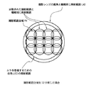
図2に撮影視野と照射野の関係を示す。従来のように、撮影視野範囲PAを単一のLEDでカバーしようとする場合の撮影レンズ系1の画角に相当する照射範囲LA0に対して、撮影視野範囲PAを6個のLED3A〜3Fでカバーしようとする場合の撮影レンズ系1の画角に相当する照射範囲LA11〜LA16には、撮影視野範囲PAを外れる無駄な照射光が非常に少ないことがわかる。
【0021】
すなわち、円筒形LEDの指向特性はLEDの前面に様々な形状の樹脂レンズが設けられたものが市販されている。LEDメーカのカタログには、照射角が10°程度の製品から照射角が80°程度の製品までさまざまな指向特性を有する品種が紹介されており、発光量が同程度ならば、指向特性における照射角が狭い程高い照射輝度を得ることができる。
この第1の実施の形態は、本発明に係る原理的な構成を示している。
今、カメラの撮影レンズ系1の画角を50°から70°とし、画面のアスペクト比を4:3として、図2に示すように、撮影視野範囲を上下に2分割し且つ左右に3分割して、全体で6分割した場合、分割された個々の撮影視野範囲に必要な照射角は、20°から30°となる。また、ちなみに図3に示すように、上下に3分割し、且つ左右に4分割して、全体で12分割した場合の分割された1つの撮影範囲に必要な照射角は、15°から22°となる。これらのように、照射角が15°〜30°近傍であるLEDはもっとも汎用性が高く、入手が容易である。
【0022】
図1は、撮影視野範囲を6分割して、6個の白色LED3A〜3Fで照明する場合の例を示している。図示のように、カメラボディCBの正面から見て右上に6個の白色LED3A〜3Fを配置して、撮影用照光装置3を構成している。先に述べたように、各白色LED3A〜3Fは、それぞれ撮影レンズ系1の光軸に対して上下・左右方向に適宜角度を付けて取り付けられており、全体としての照射野が図2のように撮影範囲全体をカバーする。
図1に示す実施の形態においては、分割された撮影範囲を照射する白色LEDは、各撮影範囲毎に1個として説明したが、もちろん複数個ずつ用いるようにしても良い。また、撮影用照光装置3を構成する各LED3A〜3Fは、図1に示すように1箇所にまとめて近接配置する必要はなく、それぞれ対応する撮影範囲を照射できればカメラボディCBのどの部分に配置しても構わない。
先に述べたように、図2および図3は、それぞれ撮影視野範囲全体を6分割する場合および12分割する場合の各分割範囲に対応する白色LEDの照射範囲を図示したものである。
このようにディスクリートタイプの白色LEDであって、しかも白色LEDの前面にそれぞれ形成されるレンズによる照射角を撮影レンズ系の画角よりも狭い複数個の白色LED3A〜3Fを使用し、各白色LEDの光軸を撮影レンズ系の光軸に対して角度を付けて配置して、撮影用照光装置3を構成し、複数個の白色LED3A〜3Fによる合成照射野で撮影視野範囲全域をカバーするようにしたため、撮影に寄与しない部分の光量を大幅に減らすことができる。
【0023】
次に、請求項1に対応する第2の実施の形態について、図4を参照して説明する。図4に示す第2の実施の形態においても撮影視野範囲を6分割して、照光するようにしている。この場合、分割された個々の範囲をそれぞれ照明する6個の照射角の狭い白色LED4A〜4Fと、撮影視野範囲のほぼ全体を照明する照射角の広い1個の白色LED4Gとによって、撮影用照光装置4を構成している。この照射角の広い1個の白色LED4Gによる照射範囲は、例えば、図2に示す照射範囲LA47のように撮影視野範囲のほぼ全体とする。
もちろん、図1に示した第1の実施の形態の場合と同様に、撮影視野範囲の分割された各部分をそれぞれ照明するのに複数個の白色LEDを用いるようにしてもよいし、撮影範囲全体を照明する白色LEDを複数個設けるようにしても良い。また、撮影用照光装置4を構成する各LED4A〜4Gは、図示のように1個所にまとめて近接配置する必要はなく、それぞれ対応する照射範囲を照射することができるようにさえすれば、カメラボディCBの何処に配置しても構わない。
【0024】
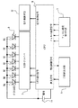
次に、請求項2〜請求項5に対応する本発明の第3の実施の形態による撮影用照光装置を組み込んだカメラの電気系の構成を図5に示すブロック図を参照して説明する。図5に示すカメラは、撮影用照光装置5、CPU(中央制御装置)6、LEDドライバ7、分割測光手段8、フィルム感度検出手段9、絞り制御手段10および電源としての電池11を備えている。
この場合、撮影用照光装置5を構成する白色LED5A〜5Fは、撮影視野範囲の分割された各領域を照明し、白色LED5Gは、照射角が撮影レンズ系の画角と概略同じかそれよりもやや狭い白色LEDである(請求項2)。
これら撮影用照光装置5を構成する白色LED5A〜5Gは、CPU6によりLEDドライバ7を介して選択的に発光制御される。分割測光手段8は、撮影視野範囲を分割し、分割された各分割範囲、すなわち分割測光範囲毎の測光結果をCPU6に送る。
【0025】
CPU6は、内蔵する記憶装置に「基準輝度情報」を格納している。この基準輝度情報は、フィルム感度検出手段9のフィルム感度出力により変化する。CPU6は、各分割範囲毎の測光結果と基準輝度とを比較し、撮影用照光装置5を構成する白色LED5A〜5Fのうち測光結果が基準輝度よりも暗いと判定された分割測光領域に対応する白色LEDを、LED選択信号により選択して、図示していないシャッタが開いている間、発光させる。
なお、撮影視野範囲の分割された各領域の画角に対応する白色LEDの照射角は、対応する分割範囲の画角と同じか、それよりもやや広くしておくことによって撮影範囲内の光量ムラを少なくする。
なお、CPU6は、分割測光手段8からの測光結果同士を比較し、輝度差がCPU6の記憶装置に予め記憶されている基準値を超えた場合に、その暗い方の測光領域に対応する白色LEDをLED選択信号により選択して、シャッタが開いている間発光させるようにしてもよい(これが請求項4に相当する)。
【0026】
また、いわゆる逆光撮影の場合には、例えば撮影視野範囲を、撮影レンズ系の光軸近傍に相当する中央部付近とその周辺部の2つの領域に分割し中央領域の輝度が周辺領域に比して、所定輝度幅以上に暗い場合は、CPU6は中央近傍を照明する白色LED、またはムラを改善するために照射角が撮影レンズ系の画角とほぼ同じかまたはやや狭い白色LED(請求項1〜図5の5Gに相当する)、あるいはそれらの両者を発光させることによって、中央の被写体の露光量を最適にする(これが請求項5に相当する)。
さらに、請求項6に対応する本発明の第4の実施の形態による撮影用照光装置を組み込んだカメラの電気系の構成を図6に示すブロック図を参照して説明する。図6に示すカメラは、撮影用照光装置12、CPU(中央制御装置)13、LEDドライバ14、分割測光手段15、フィルム感度検出手段16、絞り制御手段17、電源電池18および測距手段19を備えている。
【0027】
この場合、撮影用照光装置12を構成する白色LED12A〜12Fは、撮影視野範囲の分割された各領域を照明し、白色LED12Gは、照射角が撮影レンズ系の画角とほぼ同じかそれよりもやや狭い白色LEDである(請求項1)。
これら撮影用照光装置12を構成する白色LED12A〜12Gは、CPU13によりLEDドライバ14を介して選択的に発光制御される。分割測光手段15は、撮影視野範囲を分割し、分割された各分割範囲、すなわち分割測光範囲毎の測光結果をCPU13に送る。
測距手段19は、被写体までの被写体距離を測定し、その結果をCPU13に送る。
CPU13は、撮影視野範囲の分割された各分割測光範囲の測光結果に基づいて、発光させるべき白色LEDをLED選択信号により選択するとともに、測距手段19からの測距結果とフィルム感度検出手段16からのフィルム感度信号とに基づいて発光させるべき白色LEDの発光量を演算し、シャッタが開いている間に該当する白色LEDを発光させる。
【0028】
なお、図5または図6に示す構成において、撮影視野範囲の分割された各分割範囲に対応する白色LED5A〜5Fまたは12A〜12FのいずれかがCPU6または13の制御によって、発光する場合には、照射角が撮影レンズ系の画角とほぼ同じかあるいはやや狭い白色LED5Gまたは12Gも同時に発光するように制御してもよい(これが請求項2および4の一部に相当する)。
また、撮影レンズ系の絞りを最大、つまり絞り開放、にした場合に、白色LEDを用いた撮影用照光装置5または12による光量制御を最大限に生かすことができる。そのため、白色LEDを発光させる場合は、図5または図6に示す絞り制御手段10または17を用いて、CPU6または13からの絞り制御信号によって絞りを最大に制御する。また、シャッタ開閉羽根自体が、開口絞りを兼用している形式のシャッタの場合には、シャッタが全開になるように制御するようにしてもよい(これが請求項7に相当する)。
【0029】
さらに、図5または図6において、図示していない手段によって、セルフタイマーや赤目軽減などの機能が選択された場合には、CPU6または13は、分割された撮影範囲を照明する白色LED5A〜5Fまたは12A〜12Fのうちの複数個を同時にLEDドライバ7または14を介して発光させるようにしてもよい(これが請求項8に相当する)。この場合、白色LEDを複数個同時発光させるのは、該白色LEDの照射範囲が比較的狭いため、セルフタイマー等に使用した場合、撮影範囲の特定の場所では表示が見づらくなるのを防ぐためである。
また、同様に、図5または図6において、図示していない手段によって、セルフタイマーや赤目軽減などの機能が選択された場合に、CPU6または13は、照射角が撮影レンズ系の画角とほぼ同じかまたはやや狭い白色LED5Gまたは12Gを選択してLEDドライバ7または14を介して発光させるようにしてもよい(これが請求項9に相当する)。
【0030】
なお、上述のような表示(請求項8および請求項9に対応する表示)を行う際に、被写体を照明するときほどの白色LEDの発光量は必要でないので、CPU6または13は、LED光量制御信号をLEDドライバ7または14に送って、発光させるためのLED駆動電流を下げるなどして、光量を変化させるようにしてもよい(これが請求項10に相当する)。
上述したように、ディスクリートタイプの白色LEDであって、しかも白色LEDの前面にそれぞれ形成されるレンズによる照射角を撮影レンズ系の画角よりも狭い複数個の白色LEDを使用し、各白色LEDの光軸を撮影レンズ系の光軸に対して角度を付けて配置して、撮影用照光装置を構成し、複数個の白色LEDによる合成照射野で撮影視野範囲全域をカバーするようにしたため、撮影に寄与しない部分の光量を大幅に減らすことができる。
【0031】
さらに、撮影レンズ系の画角と同じかまたはやや狭い照射角を持つ白色LEDを追加することによって撮影視野範囲全体を照射し、発光量のムラを改善することができる。また、撮影視野範囲を分割し、分割した各分割範囲に対応した照明を行うため、従来不可能であった、撮影視野範囲内の局所照明が可能となり、より鮮明な写真撮影ができるようになる。加えて、複数の白色LEDを使用するため、本来の撮影用照明以外に一部の白色LEDを用いてセルフタイマーや、赤目防止等の他の機能にも兼用させることができ、小型化およびローコスト化にさらに貢献させることができる。
【0032】
【発明の効果】
以上述べたように、本発明によれば、発光部前面にレンズが形成されてなるディスクリートタイプの白色LEDを複数個用いて、前面に形成されるレンズによる照射角が撮影レンズの画角より狭い白色LEDを組み合わせることにより、撮影視野を効率よく照光し得る撮影用照光装置を提供することができる。
【0033】
特に、本発明の請求項1の撮影用照光装置によれば、発光部前面にレンズが形成されたディスクリートタイプの白色発光ダイオードを複数個用いて撮影視野の照明を行なうにあたり、撮影レンズの画角と概略同じか若干狭い照射角の発光照射角を有する少なくとも1つの白色発光ダイオードを、その照射野がほぼ撮影視野全域をカバーするようにその光軸を撮影レンズの光軸にほぼ平行に配置するとともに、発光照射角が撮影レンズの画角より狭い2個以上の白色発光ダイオードを、これら2個以上の発光ダイオードの組み合わせにより照射野が撮影視野全域をカバーするように、各々の光軸を撮影レンズの光軸に対して角度を付けて配置することにより、特に、複数の白色LEDによる照射ムラを改善することができる。
【0034】
本発明の請求項2の撮影用照光装置によれば、発光部前面にレンズが形成されたディスクリートタイプの白色発光ダイオードを複数個用いて撮影視野の照明を行なうに当たり、撮影レンズの画角と概略同じか若干狭い照射角の発光照射角を有し、その照射野がほぼ前記撮影視野全域をカバーするように、少なくとも一つの白色発光ダイオードを、その光軸を撮影レンズの光軸にほぼ平行に配置し、発光照射角が撮影レンズの画角より狭い2個以上の白色発光ダイオードを、これら2個以上の発光ダイオードの組み合わせによる照射野が撮影視野全域をカバーするように、各々の光軸を撮影レンズの光軸に対して角度を付けて配置するとともに、分割測光手段により、前記撮影視野全域を、各々が少なくとも1個の前記発光照射角が撮影レンズの画角より狭い白色発光ダイオードの照射野に対応する複数の分割測光領域に分割して測光し、基準輝度情報を保持する輝度判定手段により、前記分割測光手段の測光結果と前記基準輝度情報とを比較して前記測光結果が前記基準輝度を超えたか否かを判定して、前記輝度判定手段による前記分割測光領域毎の測光結果と前記基準輝度情報との比較による判定結果に基づいて発光制御手段により発光照射角が撮影レンズの画角より狭い複数の白色発光ダイオードを選択的に発光させるとともに、前記発光制御手段が、前記複数の白色発光ダイオードのうちの、前記測光結果が該基準輝度以下と判定された分割測光領域に対応する撮影視野部分を照明する白色発光ダイオードを選択的に発光させ、さらに、前記撮影レンズの画角より若干狭い照射角以上の発光照射角を有する少なくとも1つの白色発光ダイオードを同時発光させる。
このような構成により、特に、撮影範囲の各部のうちで暗い部分だけを適切に照明し、撮影範囲全体に渡ってバランスの良い明るさにすることを可能とするとともに、明るい部分を無駄に照明することがなく、省電力化を達成することができ、さらには、別個の白色発光ダイオードにより分割照明された撮影範囲の各部の輝度とその他の部分の輝度差が極端に大きくならないようにすると共に、複数の照明による光量ムラを改善することができる。
【0035】
本発明の請求項3の撮影用照光装置によれば、フィルム感度の値に応じて前記輝度判定手段に保持される前記基準輝度情報の値を変化させるためのフィルム感度設定手段をさらに具備することにより、特に、発光制御の基準輝度を使用感度に合わせて変化させ、より適切な発光基準を設定することが可能となる。
本発明の請求項4の撮影用照光装置によれば、発光部前面にレンズが形成されたディスクリートタイプの白色発光ダイオードを複数個用いて撮影視野の照明を行なうに当たり、撮影レンズの画角と概略同じか若干狭い照射角の発光照射角を有し、その照射野がほぼ撮影視野全域をカバーするように、少なくとも1つの白色発光ダイオードをその光軸を撮影レンズの光軸にほぼ平行に配置し、発光照射角が撮影レンズの画角より狭い2個以上の白色発光ダイオードを、これら2個以上の発光ダイオードの組み合わせによる照射野が撮影視野全域をカバーするように、各々の光軸を撮影レンズの光軸に対して角度を付けて配置するとともに、分割測光手段により、前記撮影視野全域を、各々が少なくとも1個の発光照射角が撮影レンズの画角より狭い前記白色発光ダイオードの照射野に対応する複数の分割測光領域に分割して測光し、前記分割測光手段の各分割測光領域で測光された輝度を、輝度比較手段が前記測光領域相互間で比較し、輝度差判定手段が、前記輝度比較手段の比較結果に基づく輝度差が所定値を超えたか否かを判定して、発光制御手段により、前記輝度差判定手段による判定結果に基づいて発光照射角が撮影レンズの画角より狭い前記複数の白色発光ダイオードを選択的に発光させるとともに、前記発光制御手段が、発光照射角が撮影レンズの画角より狭い前記複数の白色発光ダイオードのうちの、前記輝度差判定手段により前記輝度差が前記所定値を超えたと判定された2つの分割測光領域のうちの低輝度側の前記分割測光領域に対応する撮影視野部分を照明する白色発光ダイオードを選択的に発光させ、さらに前記撮影レンズの画角より若干狭い照射角以上の発光照射角を有する少なくとも1つ以上の白色発光ダイオードを同時発光させることにより、特に、撮影範囲全体が明るい場合における比較的暗い部分の黒つぶれを改善することができると共に、個別の白色LEDにより分割照明された撮影範囲の各部の輝度とその他の部分の輝度差が極端に大きくならないようにするとともに、複数の部分照明による光量ムラを改善することができる。
【0036】
本発明の請求項5の撮影用照光装置によれば、前記分割測光手段が、前記撮影視野全域を、前記撮影レンズの画角の中央近傍の部分とその周辺の部分の2つの分割測光領域に分割し、且つ前記発光制御手段が、前記輝度差判定手段により前記輝度差が前記所定値を超え、前記撮影レンズの画角の中央近傍の分割測光領域が低輝度側であると判定された場合、前記撮影レンズの画角の中央近傍の分割測光領域を照射野に含む前記白色発光ダイオードの少なくとも1つを発光させることにより、特に、逆光撮影に対応し得る撮影用照光装置を提供することにある。
本発明の請求項6の撮影用照光装置によれば、被写体距離を計測する測距手段、および適用されるフィルム感度を検出するフィルム感度検出手段を具備し、光量演算手段が、前記測距手段による測距結果および前記フィルム感度検出手段により検出されたフォルム感度に基づいて被写体に照射すべき照射光量を求め、且つ前記発光制御手段が、前記光量演算手段によって求められた照射光量に基づいて前記白色発光ダイオードの発光個数および発光光量の少なくとも一方を可変制御する構成により、特に、被写体までの距離とフィルム感度に基づき撮影範囲の各部分に対応する白色LEDの光量の設定を可能とし、より正確な露光量を得ることができる。
【0037】
本発明の請求項7の撮影用照光装置によれば、被写体照明として前記白色発光ダイオードを発光させる際には、絞り制御手段により前記撮影レンズの開口を制御する絞り手段による絞り開口を絞り開放に制御する構成により、特に、被写体を白色LEDで照明する際に、撮影レンズの絞り開口を開放、すなわち最大開口とし、白色LEDの光量を無駄なく利用することができる。
【0038】
本発明の請求項8の撮影用照光装置によれば、前記複数個の白色発光ダイオードが、他の表示、例えばセルフタイマー等、に兼用され、本発明の請求項9の撮影用照光装置によれば、前記撮影レンズの画角と概略同じか若干狭い照射角の発光照射角を有し、その照射野がほぼ撮影視野全域をカバーするように撮影光軸を撮影レンズの光軸にほぼ平行に配置した白色発光ダイオードのうちの少なくとも1つは、他の表示、例えばセルフタイマー等、に兼用され、そして本発明の請求項10の撮影用照光装置によれば、前記発光制御手段が、前記白色発光ダイオードの発光光量を可変制御する光量制御手段を含み、且つ前記光量制御手段が、前記他の表示、例えばセルフタイマー等、の際には、被写体照明の場合に比して発光光量を変える。これらの構成により、特に、照明用の白色発光ダイオードを、例えばセルフタイマー等のような、他の表示に利用することによって、小型化およびローコスト化を実現し得る。
【図面の簡単な説明】
【図1】本発明の第1の実施の形態に係る撮影用照光装置を装備したカメラの構成を模式的に示す正面図である。
【図2】図1の撮影用照光装置の6個の白色発光ダイオード(白色LED)による個々の照射野と撮影範囲との関係を模式的に示す図である。
【図3】図1の撮影用照光装置に12個の白色発光ダイオード(白色LED)を用いた場合の個々の照射野と撮影範囲との関係を模式的に示す図である。
【図4】本発明の第2の実施の形態に係る撮影用照光装置を装備したカメラの構成を模式的に示す正面図である。
【図5】本発明の第3の実施の形態に係る撮影用照光装置を装備したカメラの要部の回路構成を模式的に示すブロック図である。
【図6】本発明の第4の実施の形態に係る撮影用照光装置を装備したカメラの要部の回路構成を模式的に示すブロック図である。
【符号の説明】
1 撮影レンズ系
1a レンズバリア
2 レリーズボタン
3,4,5,12 撮影用照光装置
6,13 CPU(中央制御装置)
7,14 LED(発光ダイオード)ドライバ
8,15 分割測光手段
9,16 フィルム感度検出手段
10,17 絞り制御手段
11,18 電源電池
19 測距手段
3A〜3F、4A〜4G、5A〜5G、12A〜12G 白色発光ダイオード(白色LED)[0001]
BACKGROUND OF THE INVENTION
The present invention relates to an improvement in a photographing illumination device for irradiating a subject with illumination light when photographing with a silver salt camera using a silver salt film, an electronic camera called a digital camera, and a video camera. The present invention relates to a photographing illumination device suitable for photographing using a high sensitivity film and photographing using an electronic camera.
[0002]
[Prior art]
In recent years, the sensitivity of photographic films, so-called silver salt films, has improved, and high-sensitivity films such as ISO sensitivity of 800 to 1600 have become generally available. Furthermore, even in an electronic camera called a digital still camera or the like, the sensitivity of an image pickup device such as a CCD (charge coupled device) image pickup device has been improved, and it is not always necessary to use a large amount of light for illuminating a subject. It was.
Furthermore, the luminance of light emitting diodes (LEDs) (hereinafter referred to as “LEDs”) has been remarkably improved, and the three primary colors of light, red, green and blue, can be obtained and used for various types of lighting. It has become.
Recently, for example, JP-A-2000-89318, JP-A-2000-235245, and JP-A-10-21703 have proposed photographic illumination devices using LEDs as light sources. Japanese Patent Application Laid-Open No. 2000-89318 discloses a configuration in which a plurality of white LEDs are arranged close to each other, and in front of these LEDs, a plurality of lenses corresponding to each LED are integrally molded. It is described that it is used for illumination of a video camera.
Japanese Patent Application Laid-Open No. 2000-235245 discloses a red, blue and green LED that emits light for close-up photography of a lens-equipped film. Japanese Patent Application Laid-Open No. 10-21703 discloses a configuration for obtaining a light source with reduced irradiation unevenness by using an LED for short-distance illumination such as appearance inspection.
[0003]
[Problems to be solved by the invention]
In recent years, although the brightness of LEDs has increased, a sufficient amount of light for use in photography cannot be obtained unless a plurality of LEDs are used, and it is necessary to reduce the amount of light emission.
The shooting range of the camera is generally rectangular. However, the irradiation range of a cylindrical LED generally used for illumination is almost circular. For this reason, if the LED illumination angle is widened to cover the entire photographing range of the camera, a lot of useless portions are generated outside the photographing range PA as in the irradiation range LA0 shown in FIGS.
The present invention has been made in view of the above-described circumstances, and uses a plurality of discrete type white LEDs in which a lens is formed on the front surface of the light emitting unit, and the irradiation angle by the lens formed on the front surface is an image of the photographing lens. An object of the present invention is to provide a photographing illumination device that can efficiently illuminate a photographing field of view by combining white LEDs narrower than a corner.
[0004]
An object of claim 1 of the present invention is to provide a photographing illumination device that can improve unevenness of irradiation caused by a plurality of white LEDs.
The object of
An object of claim 3 of the present invention is to provide a photographing illumination device that can set a more appropriate light emission reference by changing the reference luminance of light emission control in accordance with the use sensitivity.
The object of claim 4 of the present invention is in particular:The brightness difference between each part of the shooting range divided and illuminated by individual white LEDs and the brightness of other parts are prevented from becoming extremely large, and the unevenness in the amount of light caused by a plurality of partial illuminations is improved.An object of the present invention is to provide a photographing illumination device capable of improving blackout in a relatively dark portion when the entire photographing range is bright.
An object of claim 5 of the present invention is to provide a photographing illumination device that can cope with backlight photographing in particular.
[0005]
The object of claim 6 of the present invention is to enable the setting of the amount of white LED light corresponding to each part of the shooting range based on the distance to the subject and the film sensitivity, and to obtain a more accurate exposure amount. An object of the present invention is to provide an illumination device.
Claims of the invention7The purpose of, in particular, white subjectsLight emitting diodeWhen illuminating with, the aperture of the taking lens is opened, that is, the maximum aperture is set, and whiteLight emitting diodeAn object of the present invention is to provide a photographing illumination device that can use the light quantity without waste.
Claims of the invention8~ Claim10The purpose of the white, especially for lightingLight emitting diodeIt is an object of the present invention to provide a photographing illumination device that can realize downsizing and low cost by utilizing the above for other displays such as a self-timer.
[0006]
[Means for Solving the Problems]
In order to achieve the above-described object, a photographing illumination device according to the present invention described in claim 1 is provided.
In a photographing illumination device that illuminates a photographing field using a plurality of discrete type white light emitting diodes in which a lens is formed on the front surface of a light emitting unit,
Shoot at least one white light-emitting diode with a light emission angle that is roughly the same as or slightly narrower than the field angle of the photographic lens so that the irradiation field covers almost the entire field of view.ThatWhile arranging the optical axis almost parallel to the optical axis of the photographic lens,
Two or more white light emitting diodes whose emission angles are narrower than the angle of view of the photographic lens, and the combination of these two or more light emitting diodes, each optic axis of the photographic lens is set so that the irradiation field covers the entire field of view. It is characterized by being arranged at an angle with respect to the optical axis.
[0007]
Moreover, in order to achieve the above-described object, a photographing illumination device according to the present invention described in
Illuminates the field of view using a plurality of discrete type white light emitting diodes with a lens formed in front of the light emitting section.In the illumination device for photography,
At least one white light-emitting diode having an emission angle that is substantially the same as or slightly narrower than the angle of view of the photographic lens, and whose irradiating field covers almost the entire field of view, and whose optical axis is the optic lens Placed almost parallel to the optical axis,
Two or more white light emitting diodes whose light emission angle is narrower than the angle of view of the photographic lens, and each optical axis of the photographic lens so that the irradiation field by the combination of these two or more light emitting diodes covers the entire field of view. It should be placed at an angle to the optical axisR,
The entire field of view is at least one eachThe emission angle is narrower than the angle of view of the taking lensSplit photometry means for measuring light by dividing into a plurality of split photometry areas corresponding to the irradiation field of the white light emitting diode;
A luminance determination unit that holds reference luminance information and compares the photometric result of the divided photometric unit with the reference luminance information to determine whether the photometric result exceeds the reference luminance;
Based on a determination result obtained by comparing the photometric result for each of the divided photometric areas by the luminance determination unit with the reference luminance information.The emission angle is narrower than the angle of view of the taking lensLight emission control means for selectively emitting light from a plurality of white light emitting diodes;
And further comprising
The light emission control unit selectively emits a white light emitting diode that illuminates a photographing field portion corresponding to a divided photometric area in which the photometric result is determined to be equal to or lower than the reference luminance among the plurality of white light emitting diodes.Let
And simultaneously emitting at least one white light emitting diode having a light emission angle that is slightly narrower than the angle of view of the photographing lens.It is characterized by.
[0008]
The photographing illumination device according to the third aspect of the present invention further includes a film sensitivity setting unit for changing the value of the reference luminance information held in the luminance determination unit in accordance with the value of the film sensitivity. It is characterized by that.
An illumination device for photographing according to the present invention described in claim 4 is:In order to achieve the above-mentioned purpose,
Illuminates the field of view using a plurality of discrete type white light emitting diodes with a lens formed in front of the light emitting section.In the illumination device for photography,
At least one white light-emitting diode having an emission angle that is substantially the same as or slightly narrower than the angle of view of the photographic lens, and whose irradiating field covers almost the entire field of view, and whose optical axis is the optic lens Placed almost parallel to the optical axis,
Two or more white light emitting diodes whose light emission angle is narrower than the angle of view of the photographic lens, and each optical axis of the photographic lens so that the irradiation field by the combination of these two or more light emitting diodes covers the entire field of view. It should be placed at an angle to the optical axisR,
The entire field of view is at least one eachThe emission angle is narrower than the angle of view of the taking lensSplit photometry means for measuring light by dividing into a plurality of split photometry areas corresponding to the irradiation field of the white light emitting diode;
Luminance comparison means for comparing the brightness measured in each divided photometry area of the divided photometry means between the photometry areas;
A luminance difference determination unit that determines whether or not a luminance difference based on a comparison result of the luminance comparison unit exceeds a predetermined value;
Based on the determination result by the luminance difference determination means,The emission angle is narrower than the angle of view of the taking lensLight emission control means for selectively emitting light from a plurality of white light emitting diodes;
And further comprising
The light emission control means includes theThe emission angle is narrower than the angle of view of the taking lensOf a plurality of white light emitting diodes, a photographing field portion corresponding to the divided photometric area on the low luminance side of the two divided photometric areas determined by the luminance difference determining means that the luminance difference has exceeded the predetermined value Selectively emits white light-emitting diodesLet
And simultaneously emitting at least one white light emitting diode having a light emission angle that is slightly narrower than the angle of view of the photographing lens.
It is characterized by.
[0009]
Claim5In the illuminating device for photographing according to the present invention described in the above, the divided photometric means includes the photographing field of view.Whole areaIs divided into two divided photometric areas, a portion near the center of the angle of view of the photographing lens and a peripheral portion thereof, and the light emission control means causes the luminance difference determination means to cause the luminance difference to exceed the predetermined value. When the divided photometric area near the center of the angle of view of the photographing lens is determined to be on the low luminance side, at least the white light emitting diode including the divided photometric area near the center of the angle of view of the photographing lens in the irradiation field One of them is characterized by emitting light.
Claim6The illumination device for photographing according to the present invention described in 1
Ranging means for measuring the subject distance;
Film sensitivity detection means for detecting the applied film sensitivity;
A light amount calculation means for obtaining an irradiation light amount to be irradiated on the subject based on a distance measurement result by the distance measurement means and a film sensitivity detected by the film sensitivity detection means;
And further comprising
The light emission control means variably controls at least one of the number of light emission and the light emission quantity of the white light emitting diode based on the irradiation light quantity obtained by the light quantity calculation means.
[0010]
Claim7The illumination device for photographing according to the present invention described in 1
A diaphragm means for controlling the aperture of the photographing lens;
When the white light emitting diode emits light as subject illumination, an aperture control means for controlling the aperture opening of the aperture means to open the aperture;
Is further included.
Claim8The illuminating device for photographing according to the present invention described in the above item is characterized in that the plurality of white light emitting diodes are also used for other displays such as a self-timer.
[0011]
Claim9The illuminating device for photographing according to the present invention described in the above has a light emitting irradiation angle that is substantially the same as or slightly narrower than the angle of view of the photographing lens, and the irradiation field covers almost the entire field of view.ThatAt least one of the white light emitting diodes whose optical axis is arranged substantially parallel to the optical axis of the photographing lens is also used as another display such as a self-timer.
Claim10In the illuminating device for photographing according to the present invention, the light emission control unit includes a light amount control unit that variably controls the light emission amount of the white light emitting diode, and the light amount control unit includes the other display, for example, self In the case of a timer or the like, the amount of emitted light is changed as compared with the case of subject illumination.
[0013]
[Action]
That is, in the illumination device for photographing according to claim 1 of the present invention, when illuminating a photographing field using a plurality of discrete type white light emitting diodes having a lens formed on the front surface of the light emitting portion, the angle of view and the outline of the photographing lens are outlined. At least one white light emitting diode with the same or slightly narrower emission angle, so that the irradiation field covers almost the entire field of view.ThatArrange the optical axis almost parallel to the optical axis of the photographic lens and shoot the two or more white light emitting diodes whose emission angle is narrower than the angle of view of the photographic lens. Each optical axis is arranged at an angle with respect to the optical axis of the photographing lens so as to cover the entire field of view.
With such a configuration, it is possible to improve unevenness in irradiation due to a plurality of white LEDs.
[0014]
The illuminating device for photographing according to
With such a configuration, in particular, it is possible to properly illuminate only the dark part of each part of the shooting range, to achieve a well-balanced brightness over the entire shooting range, and to illuminate the bright part wastefully. Power savings can be achieved withoutNot only can the brightness difference between each part of the photographing range divided and illuminated by individual white LEDs and the brightness of other parts not become extremely large, but also unevenness in the amount of light due to a plurality of partial illuminations can be improved..
[0015]
The illumination device for photographing according to claim 3 of the present invention further includes film sensitivity setting means for changing the value of the reference brightness information held in the brightness determination means in accordance with the value of film sensitivity.
With such a configuration, in particular, it is possible to set a more appropriate light emission reference by changing the reference luminance of light emission control in accordance with the use sensitivity.
The illumination device for photographing according to claim 4 of the present invention illuminates the field of view by using a plurality of discrete type white light emitting diodes having a lens formed on the front surface of the light emitting portion.At least one white light-emitting diode and its optical axis so that its irradiation field covers almost the entire field of view, with a light emission angle that is roughly the same as or slightly narrower than the angle of view of the shooting lens Placed almost parallel to the optical axis ofTwo or more white light emitting diodes whose light emission angle is narrower than the angle of view of the photographic lens, and each optical axis of the photographic lens so that the irradiation field by the combination of these two or more light emitting diodes covers the entire field of view. An angle is provided with respect to the optical axis, and the entire field of view is divided into at least one each by the divided photometric means.The emission angle is narrower than the angle of view of the taking lensThe light is divided into a plurality of divided photometry areas corresponding to the irradiation field of the white light emitting diode, and the luminance measured in each divided photometry area of the divided photometry means is compared between the photometry areas by the luminance comparison means. The luminance difference determining means determines whether or not the luminance difference based on the comparison result of the luminance comparing means exceeds a predetermined value, and based on the determination result by the luminance difference determining means by the light emission control means.The emission angle is narrower than the angle of view of the taking lensThe plurality of white light emitting diodes selectively emit light, and the light emission control means includes theThe emission angle is narrower than the angle of view of the taking lensOf a plurality of white light emitting diodes, a photographing field portion corresponding to the divided photometric area on the low luminance side of the two divided photometric areas determined by the luminance difference determining means that the luminance difference has exceeded the predetermined value The white light emitting diode that illuminatesFurthermore, at least one white light-emitting diode having a light emission angle that is slightly narrower than the angle of view of the photographing lens is simultaneously emitted.The
With such a configuration, it is possible to improve blackout in a relatively dark portion, particularly when the entire shooting range is bright.At the same time, it is possible to prevent the luminance difference between each part of the photographing range divided and illuminated by separate white light emitting diodes and the other parts from becoming extremely large, and to improve unevenness in the amount of light due to a plurality of illuminations.
[0016]
Claims of the invention5In the illumination device for photography according to the present invention, the divided photometry means has the photography field of view.Whole areaIs divided into two divided photometric areas, a portion near the center of the angle of view of the photographing lens and a peripheral portion thereof, and the light emission control means causes the luminance difference determination means to cause the luminance difference to exceed the predetermined value. When the divided photometric area near the center of the angle of view of the photographing lens is determined to be on the low luminance side, at least the white light emitting diode including the divided photometric area near the center of the angle of view of the photographing lens in the irradiation field Make one emit light.
With such a configuration, an object is to provide a photographing illumination device that can cope with backlight photographing in particular.
Claims of the invention6The illuminating device for photographing includes a distance measuring means for measuring the subject distance and a film sensitivity detecting means for detecting the applied film sensitivity, and the light amount calculating means includes the distance measurement result obtained by the distance measuring means and the film sensitivity. Based on the form sensitivity detected by the detection means, the amount of light to be irradiated to the subject is obtained, and the light emission control means determines the number of light emission and light emission of the white light emitting diodes based on the amount of light emitted by the light quantity calculation means. At least one of the light amounts is variably controlled.
With such a configuration, in particular, it is possible to set the light quantity of the white LED corresponding to each part of the photographing range based on the distance to the subject and the film sensitivity, and a more accurate exposure amount can be obtained.
[0017]
Claims of the invention7When the white light emitting diode is caused to emit light as subject illumination, the photographing illumination device according to (1) controls the diaphragm opening by the diaphragm means for controlling the opening of the photographing lens by the diaphragm control means to open the diaphragm.
With such a configuration, particularly when the subject is illuminated with a white LED, the aperture of the photographing lens is opened, that is, the maximum aperture is set, and the amount of light of the white LED can be used without waste.
[0018]
Claims of the invention8In the illuminating device for photographing, the plurality of white light emitting diodes are also used for other displays such as a self-timer.
Claims of the invention9The illuminating device for photographing has a light emitting angle of illumination that is approximately the same as or slightly narrower than the angle of view of the photographing lens, and the optical axis of the photographing lens is set so that the irradiation field covers almost the entire field of view. At least one of the white light emitting diodes arranged substantially parallel to the axis is also used for other displays such as a self-timer.
Claims of the invention10In the illuminating device for photographing, the light emission control means includes a light quantity control means for variably controlling the light emission quantity of the white light emitting diode, and the light quantity control means is used for the other display such as a self-timer. Changes the amount of emitted light as compared to subject illumination.
The above claims8~ Claim10With such a configuration, in particular, by using the white LED for illumination for other displays such as a self-timer, it is possible to realize downsizing and cost reduction.
[0019]
DETAILED DESCRIPTION OF THE INVENTION
Hereinafter, based on embodiments, a photographing illumination device of the present invention will be described in detail with reference to the drawings.
FIG. 1 shows a schematic configuration of a camera equipped with a photographing illumination device according to the first embodiment of the present invention. 1A is a detailed view showing the arrangement of the white LEDs constituting the photographing illumination device in FIG. 1 as viewed from above, and FIG. 1B is a detailed view of the photographing illumination device in FIG. It is detail drawing which shows arrangement | positioning seen from the right side surface of white LED to perform.
The camera shown in FIG. 1 has a photographing lens system 1, a
[0020]
In the photographing illumination device 3, a plurality of, in this case, six
FIG. 2 shows the relationship between the field of view and the irradiation field. As in the past, for the irradiation range LA0 corresponding to the angle of view of the photographing lens system 1 when the photographing field range PA is to be covered with a single LED, the photographing field range PA is composed of six
[0021]
That is, the directivity characteristics of cylindrical LEDs are commercially available in which resin lenses of various shapes are provided on the front surface of the LEDs. The LED manufacturer's catalog introduces products with various directional characteristics from products with an irradiation angle of about 10 ° to products with an irradiation angle of about 80 °. Higher illumination brightness can be obtained as the angle is narrower.
This first embodiment is1 shows a basic configuration according to the present invention..
Now, the angle of view of the camera's taking lens system 1 is changed from 50 ° to 70 °, the aspect ratio of the screen is set to 4: 3, and as shown in FIG. And when dividing into 6 in total, the irradiation angle required for each divided field of view is 20 ° to 30 °. In addition, as shown in FIG. 3, the irradiation angle required for one divided imaging range in the case of dividing into three in the vertical direction and four in the horizontal direction and dividing into 12 in total is 15 ° to 22 °. It becomes. As described above, LEDs having an irradiation angle in the vicinity of 15 ° to 30 ° have the highest versatility and are easily available.
[0022]
In FIG. 1, the photographing field of view is divided into six, and six white LEDs 3 </ b> A to 3FThe example in the case of illuminating with is shown. As shown in the drawing, the photographing white light device 3 is configured by arranging six
In the embodiment shown in FIG. 1, the number of white LEDs that irradiate the divided photographing ranges is described as one for each photographing range, but a plurality of white LEDs may be used as a matter of course. Moreover, each LED3A-3 which comprises the illuminating device 3 for imaging | photography.FAs shown in FIG. 1, it is not necessary to arrange them close together in one place, and any part of the camera body CB may be arranged as long as the corresponding shooting range can be irradiated.
As described above, FIG. 2 and FIG. 3 illustrate the irradiation range of the white LED corresponding to each divided range when the entire photographing field range is divided into 6 and 12 respectively.
In this way, a discrete type white LED is used, and a plurality of
[0023]
Next, the claim1A second embodiment corresponding to the above will be described with reference to FIG. Also in the second embodiment shown in FIG. 4, the photographing visual field range is divided into six parts so as to be illuminated. In this case, the illumination light for photographing is obtained by the six
Of course, as in the case of the first embodiment shown in FIG. 1, a plurality of white LEDs may be used to illuminate each of the divided parts of the photographing field of view. You may make it provide multiple white LED which illuminates the whole. Further, the
[0024]
Next, the claim2~ Claim5The configuration of the electrical system of the camera incorporating the photographing illumination device according to the third embodiment of the present invention corresponding to the above will be described with reference to the block diagram shown in FIG. The camera shown in FIG. 5 includes a photographing illumination device 5, a CPU (central control device) 6, an
In this case, the white LEDs 5A to 5F constituting the photographing illumination device 5 illuminate each divided region of the photographing visual field range, and the
The white LEDs 5 </ b> A to 5 </ b> G constituting these photographing illumination devices 5 are selectively controlled to emit light via the
[0025]
The CPU 6 stores “reference luminance information” in a built-in storage device. This reference luminance information changes depending on the film sensitivity output of the film sensitivity detection means 9. The CPU 6 compares the photometric result for each divided range with the reference luminance, and corresponds to the divided photometric area in which the photometric result is determined to be darker than the reference luminance among the white LEDs 5A to 5F constituting the photographing illumination device 5. A white LED is selected by an LED selection signal, and light is emitted while a shutter (not shown) is open.
Note that the illumination angle of the white LED corresponding to the angle of view of each divided area of the field of view is equal to or slightly wider than the angle of view of the corresponding divided range, so Reduce unevenness.
The CPU 6 compares the photometric results from the divided photometric means 8, and when the luminance difference exceeds a reference value stored in advance in the storage device of the CPU 6, the white LED corresponding to the dark photometric area. May be selected by an LED selection signal to emit light while the shutter is open.4Equivalent to
[0026]
In the case of so-called backlight photography, for example, the photographing field of view is divided into two regions, the central portion corresponding to the vicinity of the optical axis of the photographing lens system and the peripheral portion thereof, and the luminance of the central region is compared with the peripheral region. If it is darker than the predetermined brightness width, the CPU 6 illuminates the white LED in the vicinity of the center, or a white LED whose illumination angle is substantially the same as or slightly narrower than the angle of view of the photographing lens system in order to improve unevenness. (Corresponding to 5G in FIG. 5), or by making both emit light, the exposure amount of the central subject is optimized (this corresponds to claim 5).
And claims6The configuration of the electrical system of the camera incorporating the photographing illumination device according to the fourth embodiment of the present invention corresponding to the above will be described with reference to the block diagram shown in FIG. The camera shown in FIG. 6 includes a photographing
[0027]
In this case, the
The
The distance measuring means 19 measures the subject distance to the subject and sends the result to the
The
[0028]
In the configuration shown in FIG. 5 or 6, when any of the white LEDs 5A to 5F or 12A to 12F corresponding to each divided range of the photographing field range emits light under the control of the
Further, when the aperture of the photographic lens system is maximized, that is, when the aperture is opened, the light amount control by the
[0029]
Further, in FIG. 5 or FIG. 6, when a function such as a self-timer or red-eye reduction is selected by means not shown, the
Similarly, when a function such as a self-timer or red-eye reduction is selected by means not shown in FIG. 5 or FIG. 6, the
[0030]
In addition, the display as described above (claims)8And the amount of light emitted by the white LED is not as high as when illuminating the subject, the
As described above, discrete white LEDs are used, and each white LED uses a plurality of white LEDs whose irradiation angles by lenses formed on the front surface of each white LED are narrower than the angle of view of the photographing lens system. The optical axis is arranged at an angle with respect to the optical axis of the photographic lens system, and the illuminating device for photographing is configured to cover the entire photographing visual field range with a composite irradiation field by a plurality of white LEDs. The amount of light that does not contribute to shooting can be greatly reduced.
[0031]
Furthermore, by adding a white LED having an irradiation angle that is the same as or slightly narrower than the angle of view of the photographing lens system, the entire photographing visual field range can be illuminated, and unevenness in the amount of light emission can be improved. In addition, since the photographing field of view is divided and illumination corresponding to each divided range is performed, local illumination within the photographing field of view, which has been impossible in the past, is possible, and clearer photography can be performed. . In addition, since multiple white LEDs are used, some white LEDs can be used for other functions such as self-timer and red-eye prevention in addition to the original illumination for shooting. Can contribute to further development.
[0032]
【The invention's effect】
As described above, according to the present invention, by using a plurality of discrete type white LEDs in which a lens is formed on the front surface of the light emitting unit, the irradiation angle by the lens formed on the front surface is narrower than the angle of view of the photographing lens. By combining the white LED, it is possible to provide a photographing illumination device capable of efficiently illuminating the photographing field of view..
[0033]
In particular, according to the illuminating device for photographing according to claim 1 of the present invention, when the photographing field of view is illuminated using a plurality of discrete type white light emitting diodes having a lens formed on the front surface of the light emitting portion, the angle of view of the photographing lens is set.Is roughly the same asSlightly narrow irradiationHornyAt least one white light-emitting diode with a light emission angle so that its irradiation field covers almost the entire field of viewThatThe optical axis is arranged almost parallel to the optical axis of the photographic lens, and the emission angle is the angle of view of the photographic lens.ThanTwo or more narrow white light emitting diodes are arranged at an angle with respect to the optical axis of the photographing lens so that the irradiation field covers the entire field of view by combining these two or more light emitting diodes. In particular, it is possible to improve unevenness in irradiation due to a plurality of white LEDs.
[0034]
According to the photographing illumination device of the second aspect of the present invention, the photographing field of view is illuminated using a plurality of discrete type white light emitting diodes having a lens formed on the front surface of the light emitting portion.At the same time, at least one white light-emitting diode has an optical axis that has a light emission angle that is approximately the same as or slightly narrower than the angle of view of the photographic lens, and that the irradiation field covers almost the entire field of view. Is placed almost parallel to the optical axis of the photographic lens,Two or more white light emitting diodes whose light emission angle is narrower than the angle of view of the photographic lens, and each optical axis of the photographic lens so that the irradiation field by the combination of these two or more light emitting diodes covers the entire field of view. An angle is provided with respect to the optical axis, and the entire field of view is divided into at least one each by the divided photometric means.The emission angle is narrower than the angle of view of the taking lensThe brightness determination means that divides into a plurality of divided photometry areas corresponding to the irradiation field of the white light emitting diode and holds reference luminance information, and compares the photometry results of the divided photometry means with the reference luminance information. It is determined whether or not the photometric result exceeds the reference luminance, and the light emission control means based on the determination result obtained by comparing the photometric result for each of the divided photometric areas with the reference luminance information by the luminance determining means.Multiple light emission angles are narrower than the angle of view of the taking lensA white light emitting diode is selectively caused to emit light, and the light emission control means illuminates a photographing field portion corresponding to a divided photometric area in which the photometric result is determined to be equal to or lower than the reference luminance among the plurality of white light emitting diodes. Select the white light emitting diodeFurthermore, at least one white light-emitting diode having a light emission angle that is slightly narrower than the angle of view of the photographing lens is simultaneously emitted.The
With such a configuration, in particular, it is possible to properly illuminate only the dark part of each part of the shooting range, to achieve a well-balanced brightness over the entire shooting range, and to illuminate the bright part wastefully. Power savings can be achieved withoutFurthermore, it is possible to prevent the luminance difference between each part of the photographing range divided by the separate white light emitting diodes and the other parts from becoming extremely large, and to improve unevenness in the amount of light due to a plurality of illuminations..
[0035]
According to the photographing illumination device of the third aspect of the present invention, it further comprises film sensitivity setting means for changing the value of the reference luminance information held in the luminance determining means in accordance with the film sensitivity value. Thus, in particular, it becomes possible to set a more appropriate light emission reference by changing the reference luminance of light emission control in accordance with the use sensitivity.
According to the photographing illumination device of the fourth aspect of the present invention, the photographing visual field is illuminated by using a plurality of discrete type white light emitting diodes having a lens formed on the front surface of the light emitting portion.At the time of shooting, at least one white light emitting diode is photographed on its optical axis so that it has a light emission angle that is approximately the same as or slightly narrower than the angle of view of the photographic lens, and that the irradiation field covers almost the entire field of view. Place it almost parallel to the optical axis of the lens,Two or more white light emitting diodes whose light emission angle is narrower than the angle of view of the photographic lens, and each optical axis of the photographic lens so that the irradiation field by the combination of these two or more light emitting diodes covers the entire field of view. An angle with respect to the optical axis is arranged, and the entire field of view is divided into at least one by the divided photometric means.The emission angle is narrower than the angle of view of the taking lensThe light is divided into a plurality of divided photometric areas corresponding to the irradiation field of the white light emitting diode, and the luminance measured by each divided photometric area of the divided photometric means is compared between the photometric areas by the luminance comparison means. The brightness difference determining means determines whether or not the brightness difference based on the comparison result of the brightness comparing means exceeds a predetermined value, and the light emission control means is based on the determination result by the brightness difference determining means.The emission angle is narrower than the angle of view of the taking lensWhile selectively causing the plurality of white light emitting diodes to emit light, the light emission control means,The emission angle is narrower than the angle of view of the taking lensOf the plurality of white light emitting diodes, the field of view corresponding to the divided photometric area on the low luminance side of the two divided photometric areas determined by the luminance difference determining means to have exceeded the predetermined value. Select the white light emitting diode that illuminates the partIn addition, at least one white light emitting diode having a light emission angle that is slightly narrower than the angle of view of the photographing lens is simultaneously emitted.By doing so, it is possible to improve blackout in a relatively dark portion, particularly when the entire shooting range is bright.At the same time, it is possible to prevent the luminance difference between each part of the photographing range divided and illuminated by the individual white LEDs and the other parts from becoming extremely large, and to improve unevenness in the amount of light due to the plurality of partial illuminations..
[0036]
Claims of the invention5According to the photographing illumination device, the divided photometric means includes the photographing field of view.Whole areaIs divided into two divided photometric areas, a portion near the center of the angle of view of the photographing lens and a peripheral portion thereof, and the light emission control means causes the luminance difference determination means to cause the luminance difference to exceed the predetermined value. When the divided photometric area near the center of the angle of view of the photographing lens is determined to be on the low luminance side, at least the white light emitting diode including the divided photometric area near the center of the angle of view of the photographing lens in the irradiation field An object of the present invention is to provide a photographing illumination device that can cope with backlight photographing by emitting one light.
Claims of the invention6According to the illuminating device for photographing, the distance measuring means for measuring the subject distance and the film sensitivity detecting means for detecting the applied film sensitivity are provided, and the light amount calculating means includes the distance measurement result by the distance measuring means and the distance measurement means. Based on the form sensitivity detected by the film sensitivity detection means, the amount of light to be irradiated to the subject is obtained, and the light emission control means determines the number of light emission of the white light emitting diodes based on the amount of irradiation light obtained by the light quantity calculation means. In addition, the configuration that variably controls at least one of the emitted light amount enables the setting of the light amount of the white LED corresponding to each part of the shooting range based on the distance to the subject and the film sensitivity, and obtains a more accurate exposure amount. Can do.
[0037]
BookClaims of the invention7When the white light-emitting diode is caused to emit light as subject illumination, the aperture control unit controls the aperture of the imaging lens to control the aperture of the imaging lens. When the subject is illuminated with the white LED, the aperture of the photographing lens is opened, that is, the maximum aperture is set, so that the light quantity of the white LED can be used without waste.
[0038]
Claims of the invention8According to the photographing illumination device, the plurality of white light emitting diodes are also used for other displays, for example, a self-timer, and the like.9According to the photographing illumination apparatus, the photographing optical axis has a photographing light axis so that the field of view has a light emitting irradiation angle that is substantially the same as or slightly narrower than the angle of view of the photographing lens, and the irradiation field covers almost the entire photographing field. At least one of the white light emitting diodes arranged substantially parallel to the optical axis of the other is used for another display, such as a self-timer, and is claimed in the present invention.10According to the photographing illumination device, the light emission control unit includes a light amount control unit that variably controls the light emission amount of the white light emitting diode, and the light amount control unit includes the other display, such as a self-timer. In this case, the amount of emitted light is changed as compared with the case of subject illumination. With these configurations, especially white for lightingLight emitting diodeBy using this for other displays such as a self-timer, it is possible to achieve downsizing and cost reduction.
[Brief description of the drawings]
FIG. 1 is a front view schematically showing a configuration of a camera equipped with a photographing illumination device according to a first embodiment of the present invention.
2 is a diagram schematically showing a relationship between individual irradiation fields and photographing ranges by six white light emitting diodes (white LEDs) of the photographing illumination device of FIG. 1. FIG.
3 is a diagram schematically showing a relationship between individual irradiation fields and photographing ranges when twelve white light emitting diodes (white LEDs) are used in the photographing illumination device of FIG. 1. FIG.
FIG. 4 is a front view schematically showing a configuration of a camera equipped with a photographing illumination device according to a second embodiment of the present invention.
FIG. 5 is a block diagram schematically showing a circuit configuration of a main part of a camera equipped with a photographing illumination device according to a third embodiment of the present invention.
FIG. 6 is a block diagram schematically showing a circuit configuration of a main part of a camera equipped with a photographing illumination device according to a fourth embodiment of the present invention.
[Explanation of symbols]
1 Shooting lens system
1a Lens barrier
2 Release button
3, 4, 5, 12 Illumination device for photographing
6,13 CPU (Central Control Unit)
7,14 LED (light emitting diode) driver
8,15 Split photometry
9,16 Film sensitivity detection means
10, 17 Aperture control means
11, 18 Power battery
19 Ranging means
3A-3F, 4A-4G, 5A-5G, 12A-12G White light-emitting diode (white LED)
Claims (10)
撮影レンズの画角と概略同じか若干狭い照射角の発光照射角を有する少なくとも1つの白色発光ダイオードを、その照射野がほぼ撮影視野全域をカバーするようにその光軸を撮影レンズの光軸にほぼ平行に配置するとともに、
発光照射角が撮影レンズの画角より狭い2個以上の白色発光ダイオードを、これら2個以上の発光ダイオードの組み合わせにより照射野が撮影視野全域をカバーするように、各々の光軸を撮影レンズの光軸に対して角度を付けて配置したことを特徴とする撮影用照光装置。In a photographing illumination device that illuminates a photographing field using a plurality of discrete type white light emitting diodes in which a lens is formed on the front surface of a light emitting unit,
At least one white light-emitting diode having a light emission angle that is approximately the same as or slightly narrower than the angle of view of the photographic lens, with its optical axis as the optical axis of the photographic lens so that the irradiation field covers almost the entire field of view. Arrange them almost in parallel,
Two or more white light-emitting diodes whose emission angles are narrower than the angle of view of the photographic lens, and the combination of these two or more light-emitting diodes, each optical axis of the photographic lens is set so that the irradiation field covers the entire field of view. An illumination device for photographing, wherein the illumination device is arranged at an angle with respect to the optical axis.
撮影レンズの画角と概略同じか若干狭い照射角の発光照射角を有し、その照射野がほぼ前記撮影視野全域をカバーするように少なくとも1つの白色発光ダイオードを、その光軸を撮影レンズの光軸にほぼ平行に配置し、
発光照射角が撮影レンズの画角より狭い2個以上の白色発光ダイオードを、これら2個以上の発光ダイオードの組み合わせによる照射野が撮影視野全域をカバーするように、各々の光軸を撮影レンズの光軸に対して角度を付けて配置してなり、
前記撮影視野全域を、各々が少なくとも1個の前記発光照射角が撮影レンズの画角より狭い白色発光ダイオードの照射野に対応する複数の分割測光領域に分割して測光する分割測光手段と、
基準輝度情報を保持し且つ前記分割測光手段の測光結果と前記基準輝度情報とを比較して前記測光結果が前記基準輝度を超えたか否かを判定する輝度判定手段と、
前記輝度判定手段による前記分割測光領域毎の測光結果と前記基準輝度情報との比較による判定結果に基づいて前記発光照射角が撮影レンズの画角より狭い複数の白色発光ダイオードを選択的に発光させる発光制御手段と
をさらに具備し、且つ
前記発光制御手段は、前記複数の白色発光ダイオードのうちの、前記測光結果が該基準輝度以下と判定された分割測光領域に対応する撮影視野部分を照明する白色発光ダイオードを選択的に発光させ、
さらに、前記撮影レンズの画角より若干狭い照射角以上の発光照射角を有する少なくとも1つの白色発光ダイオードを同時発光させること
を特徴とする撮影用照光装置。In a photographing illumination device that illuminates a photographing field using a plurality of discrete type white light emitting diodes in which a lens is formed on the front surface of a light emitting unit,
At least one white light-emitting diode having an emission angle that is substantially the same as or slightly narrower than the angle of view of the photographic lens, and whose irradiating field covers almost the entire field of view, and whose optical axis is the optic lens Placed almost parallel to the optical axis,
Two or more white light emitting diodes whose light emission angle is narrower than the angle of view of the photographic lens, and each optical axis of the photographic lens so that the irradiation field by the combination of these two or more light emitting diodes covers the entire field of view. Ri Na arranged at an angle with respect to the optical axis,
Split photometry means for measuring the entire field of view by dividing into a plurality of split photometry areas each corresponding to an irradiation field of a white light emitting diode whose at least one light emission angle is smaller than the field angle of the taking lens ;
A luminance determination unit that holds reference luminance information and compares the photometric result of the divided photometric unit with the reference luminance information to determine whether the photometric result exceeds the reference luminance;
A plurality of white light emitting diodes whose light emission angle is narrower than the field angle of the photographing lens are selectively caused to emit light based on a determination result obtained by comparing the photometric result for each of the divided photometric areas by the luminance determination unit and the reference luminance information. A light emission control unit, and the light emission control unit illuminates a photographing field portion corresponding to a divided photometric region in which the photometric result is determined to be equal to or lower than the reference luminance among the plurality of white light emitting diodes. The white light emitting diode is selectively emitted ,
Furthermore, at least one white light emitting diode shadow for illuminating apparatus Taking the <br/> characterized thereby simultaneously emitting a having a slightly narrower irradiation angle or more luminescence irradiation angle than the angle of view of the imaging lens.
撮影レンズの画角と概略同じか若干狭い照射角の発光照射角を有し、その照射野がほぼ前記撮影視野全域をカバーするように少なくとも1つの白色発光ダイオードを、その光軸を撮影レンズの光軸にほぼ平行に配置し、
発光照射角が撮影レンズの画角より狭い2個以上の白色発光ダイオードを、これら2個以上の発光ダイオードの組み合わせによる照射野が撮影視野全域をカバーするように、各々の光軸を撮影レンズの光軸に対して角度を付けて配置してなり、
前記撮影視野全域を、各々が少なくとも1個の前記発光照射角が撮影レンズの画角より狭い白色発光ダイオードの照射野に対応する複数の分割測光領域に分割して測光する分割測光手段と、
前記分割測光手段の各分割測光領域で測光された輝度を、前記測光領域相互間で比較する輝度比較手段と、
前記輝度比較手段の比較結果に基づく輝度差が所定値を超えたか否かを判定する輝度差判定手段と、
前記輝度差判定手段による判定結果に基づいて前記発光照射角が撮影レンズの画角より狭い複数の白色発光ダイオードを選択的に発光させる発光制御手段と
をさらに具備し、且つ
前記発光制御手段は、前記発光照射角が撮影レンズの画角より狭い複数の白色発光ダイオードのうちの、前記輝度差判定手段により前記輝度差が前記所定値を超えたと判定された2つの分割測光領域のうちの低輝度側の前記分割測光領域に対応する撮影視野部分を照明する白色発光ダイオードを選択的に発光させ、
さらに、前記撮影レンズの画角より若干狭い照射角以上の発光照射角を有する少なくとも1つの白色発光ダイオードを同時発光させること
を特徴とする撮影用照光装置。In a photographing illumination device that illuminates a photographing field using a plurality of discrete type white light emitting diodes in which a lens is formed on the front surface of a light emitting unit,
At least one white light-emitting diode having an emission angle that is substantially the same as or slightly narrower than the angle of view of the photographic lens, and whose irradiating field covers almost the entire field of view, and whose optical axis is the optic lens Placed almost parallel to the optical axis,
Two or more white light emitting diodes whose light emission angle is narrower than the angle of view of the photographic lens, and each optical axis of the photographic lens so that the irradiation field by the combination of these two or more light emitting diodes covers the entire field of view. Ri Na arranged at an angle with respect to the optical axis,
Split photometry means for measuring the entire field of view by dividing into a plurality of split photometry areas each corresponding to an irradiation field of a white light emitting diode whose at least one light emission angle is smaller than the field angle of the taking lens ;
Luminance comparison means for comparing the brightness measured in each divided photometry area of the divided photometry means between the photometry areas;
A luminance difference determination unit that determines whether or not a luminance difference based on a comparison result of the luminance comparison unit exceeds a predetermined value;
A light emission control unit that selectively emits a plurality of white light emitting diodes whose light emission angle is narrower than the angle of view of the photographic lens based on a determination result by the luminance difference determination unit, and the light emission control unit comprises: Of the plurality of white light emitting diodes whose light emission angle is narrower than the angle of view of the photographing lens, the low luminance of the two divided photometric areas determined by the luminance difference determination means that the luminance difference exceeds the predetermined value The white light-emitting diode that illuminates the photographing field portion corresponding to the divided photometric area on the side is selectively emitted ;
Furthermore, at least one white light emitting diode having a light emission angle that is slightly narrower than the angle of view of the photographing lens is caused to emit light at the same time .
適用されるフィルム感度を検出するフィルム感度検出手段と、
前記測距手段による測距結果および前記フィルム感度検出手段により検出されたフィルム感度に基づいて被写体に照射すべき照射光量を求める光量演算手段と
をさらに具備し、且つ
前記発光制御手段は、前記光量演算手段によって求められた照射光量に基づいて前記白色発光ダイオードの発光個数および発光光量の少なくとも一方を可変制御することを特徴とする請求項2〜請求項5のうちのいずれか1項に記載の撮影用照光装置。Ranging means for measuring the subject distance;
Film sensitivity detection means for detecting the applied film sensitivity;
A light amount calculating means for obtaining an irradiation light amount to be irradiated on the subject based on a distance measurement result by the distance measuring means and a film sensitivity detected by the film sensitivity detection means; and the light emission control means comprises the light amount control means. 6. The control unit according to claim 2, wherein at least one of the number of emitted light and the amount of emitted light of the white light emitting diode is variably controlled based on the amount of emitted light obtained by the calculation means. Illumination device for photography.
被写体照明として前記白色発光ダイオードを発光させる際には、前記絞り手段による絞り開口を絞り開放に制御する絞り制御手段と
をさらに含むことを特徴とする請求項2〜請求項6のうちのいずれか1項に記載の撮影用照光装置。A diaphragm means for controlling the aperture of the photographing lens;
7. A diaphragm control means for controlling the diaphragm opening by the diaphragm means to open the diaphragm when the white light emitting diode emits light as subject illumination. The illumination device for photographing according to item 1.
Priority Applications (1)
| Application Number | Priority Date | Filing Date | Title |
|---|---|---|---|
| JP2000345984A JP3701190B2 (en) | 2000-11-13 | 2000-11-13 | Illumination device for photography |
Applications Claiming Priority (1)
| Application Number | Priority Date | Filing Date | Title |
|---|---|---|---|
| JP2000345984A JP3701190B2 (en) | 2000-11-13 | 2000-11-13 | Illumination device for photography |
Publications (2)
| Publication Number | Publication Date |
|---|---|
| JP2002148686A JP2002148686A (en) | 2002-05-22 |
| JP3701190B2 true JP3701190B2 (en) | 2005-09-28 |
Family
ID=18819930
Family Applications (1)
| Application Number | Title | Priority Date | Filing Date |
|---|---|---|---|
| JP2000345984A Expired - Fee Related JP3701190B2 (en) | 2000-11-13 | 2000-11-13 | Illumination device for photography |
Country Status (1)
| Country | Link |
|---|---|
| JP (1) | JP3701190B2 (en) |
Families Citing this family (15)
| Publication number | Priority date | Publication date | Assignee | Title |
|---|---|---|---|---|
| JP4040358B2 (en) | 2002-03-15 | 2008-01-30 | シャープ株式会社 | Mobile phone with shooting function |
| US7198384B2 (en) | 2003-10-02 | 2007-04-03 | Pentax Corporation | Light emitting device |
| JP2005114924A (en) | 2003-10-06 | 2005-04-28 | Pentax Corp | Illuminator for photography |
| JP2005148200A (en) | 2003-11-12 | 2005-06-09 | Pentax Corp | Light quantity controller for photography |
| JP5051965B2 (en) * | 2003-12-05 | 2012-10-17 | 株式会社ニコン | Illumination device for photographing, camera system and camera |
| JP2005301217A (en) * | 2004-03-19 | 2005-10-27 | Ricoh Co Ltd | Image photographic apparatus |
| JP4540382B2 (en) * | 2004-04-05 | 2010-09-08 | Hoya株式会社 | Lighting device for photography |
| US7509043B2 (en) * | 2004-05-25 | 2009-03-24 | Nikon Corporation | Illuminating device for photographing and camera |
| JP2005338280A (en) * | 2004-05-25 | 2005-12-08 | Nikon Corp | Illuminating device for photography and camera |
| JP2006171951A (en) * | 2004-12-14 | 2006-06-29 | Sogo Kanzai Kk | Intruder monitoring device and intruder monitoring system |
| JP2006278889A (en) * | 2005-03-30 | 2006-10-12 | Sharp Corp | Semiconductor lamp and electronic apparatus |
| JP2006323282A (en) * | 2005-05-20 | 2006-11-30 | Fujifilm Holdings Corp | Photographic apparatus |
| JP4115467B2 (en) | 2005-06-01 | 2008-07-09 | 富士フイルム株式会社 | Imaging device |
| JP4551295B2 (en) * | 2005-08-11 | 2010-09-22 | 富士フイルム株式会社 | Imaging device |
| CN113973163A (en) | 2020-07-23 | 2022-01-25 | 北京小米移动软件有限公司 | Image acquisition module, electronic device, image acquisition method and storage medium |
-
2000
- 2000-11-13 JP JP2000345984A patent/JP3701190B2/en not_active Expired - Fee Related
Also Published As
| Publication number | Publication date |
|---|---|
| JP2002148686A (en) | 2002-05-22 |
Similar Documents
| Publication | Publication Date | Title |
|---|---|---|
| JP3584355B2 (en) | Lighting equipment for photography | |
| JP3701190B2 (en) | Illumination device for photography | |
| US8385735B2 (en) | Illumination device and method, and apparatus for image taking | |
| US6369899B1 (en) | Camera with projector for selectively projecting pattern lights | |
| KR101786953B1 (en) | Light emitting device and camera system including the same | |
| US20140340573A1 (en) | Light Emitting Mobile Device Case | |
| US7859193B2 (en) | Illumination apparatus | |
| JP2005073227A (en) | Image pickup device | |
| US6930704B1 (en) | Camera for getting information upon three-dimensional shape | |
| US7663690B2 (en) | Camera executing strobe photographing using filters | |
| JP4500229B2 (en) | Imaging device | |
| JP2005114924A (en) | Illuminator for photography | |
| JP2009071404A (en) | Subject illumination control device and program thereof | |
| JP2007086178A (en) | Electronic flash unit and imaging apparatus for camera | |
| JP2009284079A (en) | Camera system and image generating method thereof | |
| KR20060045494A (en) | Illuminating device for photoshooting | |
| JP2013057927A (en) | Finder unit, imaging device and display control program | |
| JP2007110435A (en) | Photographic apparatus | |
| US20070052814A1 (en) | Method and Apparatus for white-balancing an image | |
| JP2009284078A (en) | Camera system and image generating method thereof | |
| JP2000241800A (en) | Display device of camera | |
| JP2006162717A (en) | Camera equipped with illuminator | |
| JPH0470179A (en) | Electronic still camera device | |
| JP3241868B2 (en) | Illumination device for focus detection | |
| JP2003102019A (en) | White balance adjustment device and camera system |
Legal Events
| Date | Code | Title | Description |
|---|---|---|---|
| A621 | Written request for application examination |
Free format text: JAPANESE INTERMEDIATE CODE: A621 Effective date: 20031226 |
|
| A871 | Explanation of circumstances concerning accelerated examination |
Free format text: JAPANESE INTERMEDIATE CODE: A871 Effective date: 20040305 |
|
| A975 | Report on accelerated examination |
Free format text: JAPANESE INTERMEDIATE CODE: A971005 Effective date: 20040401 |
|
| A131 | Notification of reasons for refusal |
Free format text: JAPANESE INTERMEDIATE CODE: A131 Effective date: 20040413 |
|
| A02 | Decision of refusal |
Free format text: JAPANESE INTERMEDIATE CODE: A02 Effective date: 20040713 |
|
| A521 | Request for written amendment filed |
Free format text: JAPANESE INTERMEDIATE CODE: A523 Effective date: 20040913 |
|
| A911 | Transfer to examiner for re-examination before appeal (zenchi) |
Free format text: JAPANESE INTERMEDIATE CODE: A911 Effective date: 20040930 |
|
| A912 | Re-examination (zenchi) completed and case transferred to appeal board |
Free format text: JAPANESE INTERMEDIATE CODE: A912 Effective date: 20041112 |
|
| A521 | Request for written amendment filed |
Free format text: JAPANESE INTERMEDIATE CODE: A523 Effective date: 20050314 |
|
| A61 | First payment of annual fees (during grant procedure) |
Free format text: JAPANESE INTERMEDIATE CODE: A61 Effective date: 20050712 |
|
| R150 | Certificate of patent or registration of utility model |
Free format text: JAPANESE INTERMEDIATE CODE: R150 |
|
| FPAY | Renewal fee payment (event date is renewal date of database) |
Free format text: PAYMENT UNTIL: 20090722 Year of fee payment: 4 |
|
| FPAY | Renewal fee payment (event date is renewal date of database) |
Free format text: PAYMENT UNTIL: 20090722 Year of fee payment: 4 |
|
| FPAY | Renewal fee payment (event date is renewal date of database) |
Free format text: PAYMENT UNTIL: 20100722 Year of fee payment: 5 |
|
| FPAY | Renewal fee payment (event date is renewal date of database) |
Free format text: PAYMENT UNTIL: 20110722 Year of fee payment: 6 |
|
| FPAY | Renewal fee payment (event date is renewal date of database) |
Free format text: PAYMENT UNTIL: 20120722 Year of fee payment: 7 |
|
| FPAY | Renewal fee payment (event date is renewal date of database) |
Free format text: PAYMENT UNTIL: 20120722 Year of fee payment: 7 |
|
| FPAY | Renewal fee payment (event date is renewal date of database) |
Free format text: PAYMENT UNTIL: 20130722 Year of fee payment: 8 |
|
| LAPS | Cancellation because of no payment of annual fees |