JP3700372B2 - Glass antenna device for vehicle - Google Patents
Glass antenna device for vehicle Download PDFInfo
- Publication number
- JP3700372B2 JP3700372B2 JP01976198A JP1976198A JP3700372B2 JP 3700372 B2 JP3700372 B2 JP 3700372B2 JP 01976198 A JP01976198 A JP 01976198A JP 1976198 A JP1976198 A JP 1976198A JP 3700372 B2 JP3700372 B2 JP 3700372B2
- Authority
- JP
- Japan
- Prior art keywords
- resonance
- frequency band
- coil
- band
- frequency
- Prior art date
- Legal status (The legal status is an assumption and is not a legal conclusion. Google has not performed a legal analysis and makes no representation as to the accuracy of the status listed.)
- Expired - Fee Related
Links
Images


Description
【0001】
【発明の属する技術分野】
本発明は、長波放送帯(LW帯)(150〜280kHz)、中波放送帯(530〜1630kHz)、短波放送帯(SW帯)(2.3〜26.1MHz)、FM放送帯(76〜90MHz(日本))、FM放送帯(88〜108MHz(米国))、テレビVHF帯(90〜108MHz、170〜222MHz)及びテレビUHF帯(470〜770MHz)等の受信に適し、高受信感度、低ノイズであり、かつ、生産性に富む車両用ガラスアンテナ装置に関する。
【0002】
【従来の技術】
従来、共振を利用して受信感度を向上させる車両用ガラスアンテナ装置として図7の車両用ガラスアンテナ装置が提案されている(実公平4−53070)。この従来例では、車両の後部窓ガラス板1にヒータ線2とバスバ15a、15b、15cからなるデフォッガ90を設けてバスバ15a、15bとデフォッガ90用の直流電源10との間にチョークコイル9を接続し、高周波帯域にてチョークコイル9のインピーダンスを大きくすることによって、直流電源10からデフォッガ90への直流電流は流すが放送周波数帯域等の高周波帯域の電流は遮断するようにし、デフォッガ90をアンテナとして利用している。
【0003】
また、中波放送帯においてデフォッガ90の対接地浮遊容量(以下、単に浮遊容量という)とコイル71とで並列共振させ、さらに、コイル72、コンデンサ73及び抵抗74とで中波放送帯の受信信号を通過させるようにしている。なお11はノイズカット用のコンデンサである。
図7の従来例では、このような構成を採ることにより、受信感度向上と低ノイズ化を図っている。
【0004】
しかし、この従来例では、デフォッガ90と受信機とを結線しているケーブルの浮遊容量が並列共振を生じさせる要素となっており、かつ、中波放送帯内に並列共振周波数が存在するため、S/N比が悪く、共振が1つであるため受信感度が充分でなかった。
【0005】
さらに、デフォッガ90を中波放送帯とFM放送帯との兼用アンテナとする場合、デフォッガ90の形状を中波放送受信に最適な形状としても、中波放送受信の際には、FM放送の受信感度や指向性が不充分である問題があった。
【0006】
【発明が解決しようとする課題】
本発明は従来技術の前述の欠点の解消を目的とし、高受信感度、低ノイズ及び良生産性の車両用ガラスアンテナ装置を新規に提供する。
【0007】
【課題を解決するための手段】
本発明は、ヒータ線と該ヒータ線に給電するバスバとを有する通電加熱式のデフォッガと、アンテナ導体とが車両の後部窓ガラス板に設けられており、バスバと直流電源との間、及び、バスバと車体アースとの間、の少なくとも一方にチョークコイルが接続されている車両用ガラスアンテナ装置において、
第1のコイルと第2のコイルとを備え、
アンテナ導体のインピーダンスと第1のコイルのインダクタンスとを共振要素として含む第1の共振を生じさせており、第1の共振が直列共振であり、
第2のコイルとチョークコイルとの並列接続回路のインダクタンスと、デフォッガのインピーダンスとが第2の共振の主な共振要素となり、第2の共振が並列共振であり、
第1の受信周波数帯の受信信号と第1の受信周波数帯より高周波数の第2の受信周波数帯の受信信号とがアンテナ導体より受信機に送られており、
アンテナ導体と受信機との間に第1のコイルが電気的に接続されており、デフォッガと車体アースとの間に第2のコイルが電気的に接続されており、
第1の受信周波数帯の最高周波数をf H とした場合、f H の1.5倍の周波数と第1の受信周波数帯の略中心周波数との間に第1の共振の共振周波数を存在させ、かつ、第1の受信周波数帯の最低周波数をf L とした場合、f L の0.6倍の周波数と第1の受信周波数帯の略中心周波数との間に第2の共振の共振周波数を存在させており、
アンテナ導体とデフォッガとの間に、第2の受信周波数帯の受信信号を遮断又は減衰させるフィルタ回路が電気的に接続されていることを特徴とする車両用ガラスアンテナ装置を提供する。
【0008】
【0009】
【0010】
【0011】
【0012】
【0013】
【発明の実施の形態】
図1は自動車の後部窓ガラス板1を使用した本発明の車両用ガラスアンテナ装置の基本的構成図である。図1において、2はヒータ線、3aはアンテナ導体、4aは給電点、5a、5bはバスバ、6は共振回路、7は受信機、31は第1のコイル、32は第2のコイル、90はデフォッガ、91はデフォッガ90に接続された引き出し線条の先端に設けられた給電点である。
【0014】
アンテナ導体3aとデフォッガ90とが容量結合されるための両者間の距離は、通常0.1〜50mm程度である。容量結合されたアンテナ導体3aとデフォガ90との間では直流電流の送受は行われないが受信信号の高周波電流の送受は行われる。
【0015】
【0016】
【0017】
アンテナ導体3aとデフォッガ90とを近接させて容量結合させてもよい。
【0018】
チョークコイル9を設けず、デフォッガ90と直流電源10とを直接接続した場合には、放送周波数帯域にてデフォッガ90を車体アースから遮断しないこととなり、容量結合された容量が大きすぎると、かえってアンテナ導体3aに誘起された受信信号がデフォッガ90を通して車体アースに漏れてしまい、受信感度が減少する。
【0019】
また、容量結合された容量が大きすぎると、デフォッガ90に存在するエンジンノイズがアンテナ導体3aに流れ、S/N比も悪くなる。チョークコイル9を設けない場合には、アンテナ導体3aとデフォッガ90との結合容量は通常100pF以下が好ましい。100pF以下の場合には、100pF超の場合と比較して通常0.5dB以上受信感度が向上する。
【0020】
同様に、S/N比の観点から、通常アンテナ導体3aとデフォッガ90との結合容量は50pF以下が好ましい。50pF以下の場合には、50pF超の場合と比較して通常2.0dB以上S/N比が向上する。より好ましい範囲は25pF以下である。25pF以下の場合には、25pF超の場合と比較して通常3.0dB以上S/N比が向上する。
【0021】
図1に示すように後部窓のガラス板1に設けられている複数本のヒータ線2のバスバ以外の部分を短絡線により短絡してもよい。ヒータ線2をバスバ以外の部分で短絡する短絡線21は必要に応じて設けられ、デフォッガ90をアンテナとして利用する場合に、デフォッガ90のインピーダンスを安定させる機能を有する。また、短絡線21は高帯域化機能をも有する。
【0022】
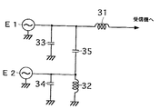
図2は図1の装置においてアンテナ導体3aとデフォガ90とを容量結合させた場合の等価回路図である。図2において、E1はアンテナ導体3aの電圧電源、E2はデフォガ90の電圧電源、33はアンテナ導体3aの浮遊容量、34はデフォガ90の浮遊容量、35はアンテナ導体3aとデフォガ90の近接容量である。
【0023】
デフォガ90は主に第1の受信周波数帯(以下、低域周波数帯という)の受信用とすることが好ましく、低域周波数帯で好適な受信性能が得られるように導体長及び導体形状を設定することが好ましい。アンテナ導体3aは低域周波数帯より高周波数の第2の受信周波数帯(以下、高域周波数帯という)の受信用とすることが好ましく、高域周波数帯で好適な受信性能が得られるように導体長及び導体形状を設定することが好ましい。
【0024】
例えば、高域周波数帯をFM放送帯、テレビVHF帯又はテレビUHF帯とする場合、アンテナ導体3aを構成する各エレメントの横幅の寸法は、ガラス短縮率をK、高域周波数帯の最高周波数の波長をλH 、高域周波数帯の最低周波数の波長をλL としたとき、(λH /4)×K〜λL ×Kの範囲が好ましい。なお、ガラス短縮率Kは0.64である。
【0025】
低域周波数帯を中波放送帯とする場合、デフォガ90の導体長は使用できるエリアを最大限に使い、できるだけ長くすることが好ましい。
【0026】
アンテナ導体3a、デフォガ90は、中波放送帯、FM放送帯、短波放送帯、長波放送帯、テレビVHF帯、テレビUHF帯及び電話受信用等とできる。例えば、一般的には、低域周波数帯を中波放送帯とし、高域周波数帯をFM放送帯、テレビVHF帯及びテレビUHF帯の1以上とする。
【0027】
本発明においては、2つの共振を起こして受信感度を向上させる。第1の共振については、アンテナ導体のインピーダンスと第1のコイルのインダクタンスとが共振要素として含まれる。
【0028】
アンテナ導体3aのインピーダンスは主に浮遊容量33からなり、アンテナ導体3aのインピーダンスとは給電点4aからアンテナ導体3a側を見たときのインピーダンスをいう。また、浮遊容量33と車体アースとの間に並列に容量成分を接続して第1の共振の共振周波数を調整してもよい。この容量成分も第1の共振の共振要素となりうる。
【0029】
また、第1の共振には、第1のコイル31周辺の配線の浮遊容量、ガラスアンテナと受信機との間に接続されているケーブルの浮遊容量及び近接容量35も影響し、これらも第1の共振の共振要素となりうる。
【0030】
また、共振回路6内部に新たに回路素子を設けてアンテナ導体3aと受信機側とのインピーダンスマッチングを行ってもよい。第1のコイル31には通常10μH〜1mH程度のものが使用される。
【0031】
第2の共振については、デフォガ90のインピーダンスと第2のコイルのインダクタンスとが共振要素として含まれる。デフォガ90のインピーダンスは主に浮遊容量34からなり、デフォガ90のインピーダンスとは給電点4bからデフォガ90側を見たときのインピーダンスをいう。また、浮遊容量34と車体アースとの間に並列に容量成分を接続して第2の共振の共振周波数を調整してもよい。この容量成分も第2の共振の共振要素となりうる。
【0032】
第2のコイル32には通常10μH〜1mH程度のものが使用される。また、第2の共振には、第2のコイル32周辺の配線の浮遊容量及び近接容量35も、第2の共振の共振要素となりうる。共振回路6と受信機との間に接続されているケーブルの浮遊容量も第2の共振に影響を与える。
【0033】
なお、第2のコイル32が、放送周波数のうちでもFM放送周波数のような高い周波数帯でインダクタンスを失う(すなわち、容量性の性質となる)場合には、受信信号が車体アースに漏れ、受信感度が落ちる。これを防ぐために、第2のコイル32に高周波チョークコイル(不図示)を直列に接続してもよい。この高周波チョークコイルには通常0.1〜100μH程度が使用される。
【0034】
アンテナ導体3aとデフォガ90とを容量結合させた場合、デフォガ90の受信信号は近接容量35を介して受信機側に伝達される。共振回路6内部に新たに回路素子を設けてデフォガ90と受信機側とのインピーダンスマッチングを行ってもよい。図1では、第1の共振は直列共振であり、第2の共振は並列共振である。
【0035】
本発明において2つの共振を生じさせるのは、1つの共振のみでは幅広い受信周波数帯域をカバーしきれないからである。したがって本発明では低域周波数帯域を略中心周波数で2つに分けて、それぞれを2つの共振で分担させ受信感度の平坦化を図ることが望ましい。ここで、受信感度の平坦化とは、低域周波数帯等の帯域内で最高受信感度と最低受信感度との差を小さくすることをいう。
【0036】
また、第1の共振の共振周波数及び第2の共振の共振周波数は、低域周波数帯の感度が向上するような周波数とする。しかし、低域周波数帯の最高周波数をfH とした場合、fH の1.5倍の周波数と低域周波数帯の略中心周波数との間に第1の共振の共振周波数を存在させ、かつ、低域周波数帯の最低周波数をfL とした場合、fL の0.6倍の周波数と低域周波数帯の略中心周波数との間に第2の共振の共振周波数を存在させる。受信感度の平坦化の面で好ましいからである。この範囲外であると、低域周波数帯域内で最高受信感度と最低受信感度との差が通常10dB程度以下とすることが困難となり、低域周波数帯で受信感度の平坦化が劣る。
【0037】
また、第1の共振の共振周波数は、低域周波数帯域内に存在することが受信感度向上の面で好ましい。低域周波数帯域内に存在する場合には、存在しない場合と比較して低域周波数帯全域の受信感度が通常10dB程度向上する。
【0038】
したがって、平坦化及び受信感度の両面を向上させるため、fH と低域周波数帯の略中心周波数との間に第1の共振の共振周波数を存在させ、かつ、fL の0.6倍の周波数と低域周波数帯の略中心周波数との間に第2の共振の共振周波数を存在させることが好ましい。
【0039】
第1の共振が直列共振である場合、第1の共振の共振周波数は、低域周波数帯域の略中心周波数より高いことが好ましい。第2の共振が並列共振である場合、第2の共振の共振周波数は、低域周波数帯域の略中心周波数より低いことが好ましい。第2の共振が並列共振である場合には並列共振の共振周波数より低い範囲の受信感度の低下が著しい。
【0040】
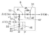
図3は共振回路6の変更例の回路図である。図3において、41、44、50、51は直流カット用のコンデンサ、42はバイパスコンデンサ、43は結合用のコンデンサ、45、46、48、49はダンピング用の抵抗、47はエンジンノイズ等の車両ノイズの軽減用の抵抗である。
【0041】
図3の共振回路では、デフォガ90の受信信号はコンデンサ51、抵抗47、コンデンサ43を介して受信機側に伝達される。ただし、アンテナ導体3aとデフォガ90とが容量結合されている場合には、デフォガ90の受信信号は近接容量35を介しても受信機側に伝達される。
【0042】
バイパスコンデンサ42は必要に応じて設けられ、高域周波数帯を通過させて、受信機側に送る機能を有する。例えば、低域周波数帯を中波放送帯とするとき、FM放送受信をも行う場合には、FM放送帯をバイパスコンデンサ42によって通過させる。
【0043】
コンデンサ43はアンテナ導体3aとデフォガ90との容量結合を強化するためのものであり、必要に応じて設けられる。アンテナ導体3aとデフォガ90との接続については、図3の場合ではコンデンサ43で行っている。しかし、抵抗等他の部品で接続させてもよい。また、受信感度の平坦化を調整するものとして、抵抗45、46、48、49は必要に応じて設けられる。この他に共振調整用のコンデンサ等を設けてもよい。
【0044】
コンデンサ41、44、50、51は必要に応じて設けられ、通常100pF〜50μFが使用される。バイパスコンデンサ42には通常1〜1000pFが使用される。コンデンサ43には通常5〜500pFが使用される。抵抗45、46、49には通常50Ω〜100kΩが使用される。
【0045】
共振回路6と受信機7とを接続するケーブルの浮遊容量が第2の共振に影響を与えてエンジンノイズ等の車両ノイズによるS/N比の悪化を招く。抵抗47は必要に応じて設けられ、このS/N比悪化を防止する機能を有する。特に中波放送帯の低域のS/N比悪化を防止する機能を有する。すなわち、抵抗47はエンジンノイズ等の車両ノイズの軽減する機能を有する。
【0046】
抵抗47の抵抗値は10Ω〜1kΩが好ましく、50〜500Ωが好ましい。低域周波数帯を中波放送帯とするとき、抵抗47の抵抗値を10Ω〜1kΩとする場合には、10Ω〜1kΩの範囲外の場合と比較して、中波放送帯のS/N比が1dB以上向上する。抵抗47の抵抗値を50〜500Ωとする場合には、50〜500Ωの範囲外の場合と比較して、中波放送帯のS/N比が1dB以上向上する。
【0047】
前述した通り、図3において、コンデンサ41、42、43、44、50、51、抵抗45、46、47、48、49は必要に応じて設けられ、省略でき、ここで、コンデンサ42の省略、抵抗45、46、49の省略とは開放とすることであり、コンデンサ41、43、44、50、51の省略、抵抗47、48の省略とは短絡とすることである。
【0048】
図6は図3とは別タイプの共振回路の回路図を示す。図6において、52は高周波チョークコイルである。高周波チョークコイル52は必要に応じて設けられる。高周波チョークコイル52の省略とは短絡とすることである。
【0049】
高周波チョークコイル52は、アンテナ導体3aとデフォガ90とを通常高域周波数帯で高周波的に分離し、アンテナ導体3aの導体の実効長を変化させず、高域周波数帯で受信感度を向上させる機能を有する。高周波チョークコイル52は、0.1〜1000μH程度が通常使用される。
【0050】
また、第2のコイル32が高域周波数帯で自己共振周波数が低く、インダクタンスを失う場合には、アンテナ導体3aに励起される高域周波数帯の受信信号が第2のコイル32を介して車体アースに漏れ受信感度が落ちるため、高域周波数帯でインダクタンスを失わない(すなわち、容量性の性質とならない)高周波チョークコイル52により高域周波数帯の受信信号が第2のコイル32を介して車体アースに漏れるのを防止できる。
【0051】
換言すると、高周波チョークコイル52は、低域周波数帯の周波数を通過させ、高域周波数帯の周波数を遮断又は減衰するフィルタ機能を有する。高周波チョークコイル52を設ける場合には、設けない場合と比較して、高域周波数帯受信感度が通常1dB以上向上する。
【0052】
図6において、アンテナ導体3aに励起した高域周波数帯の受信信号が車体アースに漏れることを防止するため、アンテナ導体3aとデフォガ90との間に高周波チョークコイル52を接続している。しかし、これに限定されず、アンテナ導体3aとデフォガ90との間に接続するものは高域周波数帯の受信信号を遮断又は減衰させるフィルタ回路であればどのようなものであってもよい。
【0053】
【0054】
【0055】
【0056】
受信感度向上のために、デフォッガ90と、アンテナ導体3aを近接させて容量結合させてもよい。完全に容量結合させた場合には、図1に示すように、デフォッガ90とデフォッガ90用の直流電源10との間にチョークコイル9を接続し、デフォッガ90を車体アースから絶縁することが好ましい。このようにして容量結合させる場合には、容量結合させない場合と比較して、受信感度が数dB以上向上する。容量結合されるための両者間の距離は、通常0.1〜50mm程度である。チョークコイル9は通常0.1〜10mH程度が使用される。
【0057】
図1においては、バスバ5a、5bとデフォッガ90用の直流電源10との間にチョークコイル9及び高周波チョークコイル12a、12bを挿入し、放送周波数帯域にてチョークコイル9及び高周波チョークコイル12a、12bのインピーダンスを大きくすることによって、直流電源10からデフォッガ90への直流電流は流すが放送周波数帯域の電流は遮断するようにしている。
【0058】
このようにして、チョークコイル9及び高周波チョークコイル12a、12bによりデフォッガ90のヒータ線2とバスバ5a、5bとを車体アースから高周波的に絶縁でき、デフォッガ90に誘起された放送周波数帯の受信電流が車体アースへ流れるのを防止できて、この受信電流を漏れなく受信機に送れる。
【0059】
高周波チョークコイル12a、12bは、放送周波数帯のうちでもFM放送周波数帯のような高い周波数帯において、高インピーダンスとなるもので、通常はソレノイド又は磁気コアを使用する。これらはFM放送周波数帯のような高い周波数帯及びその周波数帯の近傍では誘導性のインダクタンスを有する。チョークコイル9はFM放送周波数帯のような高い周波数帯では自己共振周波数が低く、インダクタンスを失う場合があるので、高周波チョークコイル12a、12bがこれを代行する。高周波チョークコイル12a、12bは0.1〜100μH程度が通常使用される。
【0060】
チョークコイル9がFM放送周波数帯のような高い周波数帯でインダクタンスを失う場合には、高周波チョークコイル12a、12bは不要である。要するに、AM放送周波数帯のような低い周波数帯のみを受信する場合であれば、高周波チョークコイル12a、12bは通常不要であり、チョークコイル9のみでよく、FM放送周波数帯のような高い周波数帯のみを受信する場合であれば、高周波チョークコイル12a、12bのみでよい。低い周波数帯及び高い周波数帯両方を受信する場合であっても、チョークコイル9、高周波チョークコイル12a、12b両方の機能を満足するコイルがあれば、かかるコイルのみでよい。
【0061】
【0062】
【0063】
図1において、コンデンサ51が設けられてなく、コンデンサ51の箇所が短絡されているならば、デフォッガ90に流れる直流電流が第2のコイル32に流れ込むため、第2のコイル32の電流容量を大きくしなければならず、生産性が悪くなり、さらに、デフォッガ90に流れる直流電流がコイル32を介して車体アースに流れ込むため、電流が無駄になる。したがって、コンデンサ51を設けることが好ましい。
【0064】
図1ではコンデンサ51は、給電点91と第2のコイル32との間に接続されており、給電点91がバスバ5bに接続されているので、バスバ5bと第2のコイル32との間に接続されている。しかし、これに限定されず、コンデンサ51は、バスバ5aと第2のコイル32との間に接続されていてもよく、ヒータ線2と第2のコイル32との間に接続されていてもよい。換言すれば、第2のコイル32が接続されるデフォッガ90の箇所は限定されない。
【0065】
【0066】
前述したとおり、浮遊容量33と車体アースとの間に並列に容量成分を接続して第1の共振の共振周波数を調整してもよい。この容量成分も第1の共振の共振要素となりうる。
また、アンテナ導体3aとデフォッガ90とが電気的に接続されているため、第1の共振にはデフォッガ90のインピーダンスも影響し、第1の共振の共振要素となりうる。
【0067】
デフォッガ90のインピーダンスは主に浮遊容量34からなり、デフォッガ90のインピーダンスとは給電点91からデフォッガ90側を見たときのインピーダンスをいう。さらに、第1の共振には、第1のコイル31周辺の配線の浮遊容量、ガラスアンテナと受信機との間に接続されているケーブルの浮遊容量及び近接容量35も影響し、第1の共振の共振要素となりうる。第1の共振は図1においては直列共振である。
【0068】
共振回路6内部に新たに回路素子を設けてアンテナ導体3aと受信機側とのインピーダンスマッチングを行ってもよい。第1のコイル31には通常10μH〜1mH程度のものが使用される。
【0069】
第2の共振については、第2のコイル32のインダクタンス及びチョークコイル9のインダクタンスの少なくとも一方とデフォッガ90のインピーダンスとが共振要素として含まれる。
【0070】
また、アンテナ導体3aとデフォッガ90とが電気的に接続されているため、第2の共振にはアンテナ導体3aのインピーダンスも影響し、第2の共振の共振要素となりうる。
さらに、第2の共振には、アンテナ導体3a周辺の配線の浮遊容量、デフォッガ90周辺の配線の浮遊容量、第2のコイル32周辺の配線の浮遊容量及び近接容量35も影響し、第2の共振の共振要素となりうる。共振回路6の出力と受信機との間に接続されているケーブルの浮遊容量も第2の共振に影響を与える。また、図1における第2の共振は並列共振である。
【0071】
【0072】
【0073】
図1において、第1の共振の共振周波数及び第2の共振の共振周波数は、低域周波数帯の感度が向上するような周波数とする。低域周波数帯を中波放送帯とするとき、S/N比向上の観点より、並列共振の共振周波数は350〜530kHzが好ましく、450〜500kHzがより好ましい。
【0074】
また、浮遊容量34と車体アースとの間に並列に容量成分を接続して第2の共振の共振周波数を調整してもよい。この容量成分も第2の共振の共振要素となりうる。第2のコイル32には通常10μH〜1mH程度のものが使用される。
【0075】
図1において、インダクタンス素子である高周波チョークコイル52は必要に応じて設けられ、高周波チョークコイル52は、アンテナ導体3aとデフォッガ90とを通常高域周波数帯で高周波的に分離し、アンテナ導体3aの導体の実効長を変化させず、高域周波数帯で受信感度を向上させる機能を有する。
【0076】
また、高周波チョークコイル52が設けられていない場合であって、チョークコイル9又は第2のコイル32が高域周波数帯では自己共振周波数が低く、容量性の性質が強くなる場合には、アンテナ導体3aに励起した高域周波数帯の受信信号が車体アースの漏れるため、高周波チョークコイル52を設けてこれを防ぐようにする。図1における高周波チョークコイル52は、0.1〜1000μH程度が通常使用され、高周波チョークコイル52を設けることにより、高域周波数帯の感度が0.3dB以上向上するように高周波チョークコイル52のインダクタンス値を設定することが好ましい。
【0077】
また、低域周波数帯を中波放送帯とし、高域周波数帯をFM放送帯、テレビVHF帯及びテレビUHF帯の1以上とする場合には、高周波チョークコイル52は、0.5〜10μHが通常使用される。高周波チョークコイル52は、0.5〜10μHの範囲内の場合には0.5〜10μHの範囲外の場合と比較して、2dB以上感度が向上する。
【0078】
図1において、アンテナ導体3aに励起した高域周波数帯の受信信号が車体アースの漏れることを防止するため、アンテナ導体3aとデフォッガ90との間に高周波チョークコイル52を接続した。しかし、これに限定されず、アンテナ導体3aとデフォッガ90との間に接続するものは高域周波数帯の受信信号を遮断又は減衰させるフィルタ回路であればどのようなものであってもよい。
【0079】
また、図1において、アンテナ導体3aとデフォッガ90とは容量結合していない方が好ましい。容量結合させる場合には、アンテナ導体3aに励起した高域周波数帯の受信信号がデフォッガ90、チョークコイル9を介して車体アースに漏れやすくなる。
【0080】
図4は、図1の車両用ガラスアンテナ装置を発展させてダイバーシティ受信を行うようにしたものである。図4において、53はコンデンサ、t1 は受信機7の第1の入力、t2 は受信機7の第2の入力である。受信機7では、第1の入力t1 と第2の入力t2 との間の、高域周波数帯の受信信号のうち、強い方を選択する。
【0081】
コンデンサ53は必要に応じて設けられ、低域周波数帯の受信信号を遮断又は減衰させる機能を有する。コンデンサ53の容量値は10〜150pFが好ましく、20〜70pFがより好ましい。低域周波数帯が中波放送帯の場合、コンデンサ53の容量値を10〜150pFとする場合には、10〜150pFの範囲外の場合と比較して、中波放送帯の感度が1dB以上向上する。コンデンサ53の容量値を20〜70pFとする場合には、20〜70pFの範囲外の場合と比較して、中波放送帯の感度が1dB以上向上する。
【0082】
図4の車両用ガラスアンテナ装置では、高周波チョークコイル12a、12bをバスバとチョークコイル9との間に接続することが好ましい。図1の装置では使用しない、デフォッガ90に励起された高域周波数帯の受信信号を第2の入力t2 で使用するため、高周波チョークコイル12a、12bにてデフォッガ90に励起された高域周波数帯の受信信号の車体アースへの漏れを防止するためである。なお、図4の共振回路6は図1の車両用ガラスアンテナ装置にも応用できる。
【0083】
【0084】
図1、4に示したデフォッガ90は、いわゆる略ハの字状であるが、本発明にかかるデフォッガ90はこれに限定されず、図7に示すようないわゆる略コの字状デフォッガ90であっても、本発明に利用できる。
アンテナ導体3a及びデフォガ90は、窓ガラス板1のデフォッガ90よりも上、下、左、又は右の余白部のどこに設けてもよく、図1に示す位置に限定されない。また、窓ガラス板1に設けられるアンテナ導体の数は2以上であれば限定されない。
【0085】
本発明においては、アンテナ導体3a及びデフォガ90以外に車両に設けられるアンテナ導体の数は限定されない。また、本発明のガラスアンテナ装置、ポールアンテナ等の他のアンテナ装置又は他のガラスアンテナ装置との間でダイバーシティ受信を行ってもよい。
【0086】
給電点4a、4bは図1では窓ガラス板1の右周縁部に配設されているが、これに限定されず、窓ガラス板1のどの位置に配設されていてもよく、例えば、窓ガラス板1の左右中央の上下周縁部に配設されていてもよい。
【0087】
図1に示すアンテナ導体3a及びデフォガ90には補助アンテナ導体は付設されていない。しかし、位相調整及び指向性調整のために、これらのアンテナ導体の導体パターン又は給電点に、略T字状、略L字状等の補助アンテナ導体が付設されていてもよい。
【0088】
また、本発明において、アンテナ導体3a及びデフォガ90が設けられる窓ガラス板は後部窓ガラス板に限定されず、サイド窓ガラス板、前部窓ガラス板、ルーフ窓ガラス板等であってもよく、アンテナ導体が設けられる窓ガラス板にデフォッガ90が設けられていなくともよい。
【0089】
【実施例】
【0090】
【0091】
【0092】
【0093】
【0094】
【0095】
【0096】
「例1(比較例)」
図7に示すような従来の車両用ガラスアンテナ装置を製作した。コイル71は680μH、コイル72は100μH、コンデンサ73は30pF、抵抗74は5kΩとした。窓ガラス板と、窓ガラス板に設けられるデフォッガ90とは例1と同様のものを使用した。
【0097】
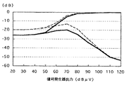
図5は600kHzにおけるS/N特性図である。シールドルーム内で信号発生器に接続した送信用アンテナから電波を放射して測定した。図5の横軸は信号発生器の出力電圧、縦軸は受信機最終段の低周波増幅回路の出力電圧をdBで表示したものである。信号発生器の出力を120dBμVとして、S/Nが飽和状態にさせるために受信機に入力を充分に入れた(飽和状態)。このとき、信号発生器の変調については400Hzの変調周波数を採用し30%の変調度とした。また、このときの状態を縦軸の0(ゼロ)dBとして基準とした。
【0098】
図5において、実線が例1の、波線が例2の、S/N特性である。50〜120dBμVにおいて、実線、波線ともに上下に分枝している。分枝の上の線は変調させた場合の状態であり(音声信号(S)+ノイズ(N))、分枝の下の線は送信用アンテナからの電波に変調を全く加えていない状態である(無変調状態、ノイズ(N)のみ)。
【0099】
図5における上の線と下の線のdBの差異が大きいほどS/N比が大きく、良好な受信ができる。なお、図5のS/N特性はエンジンノイズ等の車両ノイズは無関係であり、エンジンの作動又は停止に影響されない。
【0100】
【0101】
【0102】
【0103】
【0104】
【0105】
【0106】
「例2(実施例)」
自動車の後部窓ガラス板を使用し、図1に示すようなガラスアンテナ装置を製作した。各回路定数は以下のとおりである。
第1のコイル31 =150μH、
第2のコイル32 =560μH、
高周波チョークコイル52 =2.2μH、
バイパスコンデンサ42 =22pF、
抵抗45 =15kΩ、
抵抗47 =270Ω、
抵抗48 =220Ω、
コンデンサ50、51 =1000pF、
チョークコイル9 =1.6mH、
デフォッガ90の浮遊容量 =100pF。
【0107】
アンテナ導体3aは中波放送帯及びFM放送帯を受信できるように導体長、導体形状を調整した。アンテナ導体3aの下部とヒータ線2の最上線との間隔を15mmと長くした。この場合、アンテナ導体3aとデフォッガ90とは、わずかに容量結合していた。
【0108】
図8は中波放送帯の感度の特性図である。図8では910mmの長さのポールアンテナとの感度を比較しており、ポールアンテナの感度は0dBである。第1の共振(直列共振)の共振周波数は1450kHz、第2の共振(並列共振)の共振周波数は480kHzであった。図9はFM放送帯の感度の特性図である。
【0109】
【発明の効果】
本発明では、アンテナ導体のインピーダンスと第1のコイルのインダクタンスとを共振要素として含む第1の共振を生じさせ、デフォガのインピーダンス第2のコイルのインダクタンスとを共振要素として含む第2の共振を生じさせており、2共振を利用するため感度に優れる。さらに、ガラスアンテナと受信機との間に接続されているケーブルの浮遊容量については第2の共振に与える影響が少ないため、S/N比が飛躍的に向上する。
【0110】
本発明では、低域周波数帯、高域周波数帯の2つの異なる周波数帯を受信する場合であっても、アンテナ導体を高域周波数帯受信に適するように設計し、デフォガを低域周波数帯受信に適するように設計することによって、両周波数帯とも良好に受信できる。さらには、両周波数帯受信のための調整を別々に行えるため、調整が容易となり、生産性向上に寄与できる。
【0111】
【0112】
低域周波数帯受信の際には、アンテナ導体とデフォッガの両方を利用できるため低域周波数帯の感度に優れ、高域周波数帯受信の際には、アンテナ導体のみの実効長を利用できるため高域周波数帯の感度に優れる。
【図面の簡単な説明】
【図1】本発明の車両用ガラスアンテナ装置の基本的構成図
【図2】図1の装置においてアンテナ導体3aとデフォガ90とを容量結合させた場合の等価回路図
【図3】共振回路6の変更例の回路図
【図4】図1とは別のタイプの本発明の車両用ガラスアンテナ装置の構成図
【図5】例1及び従来例のS/N特性図
【図6】図3とは別のタイプの共振回路6の回路図
【図7】従来技術のアンテナ装置の構成図
【図8】例6の中波放送帯の感度の特性図
【図9】例6のFM放送帯の感度の特性図
【符号の説明】
1:車両の後部窓ガラス板
2:ヒータ線
3a:アンテナ導体
4a:給電点
5a、5b:バスバ
6:共振回路
7:受信機
10:直流電源
31:第1のコイル
32:第2のコイル
33:アンテナ導体3aの浮遊容量
34:デフォガ90の浮遊容量
35:近接容量
41、44:直流カット用コンデンサ
42:バイパスコンデンサ
43:結合コンデンサ
45、46:ダンピング用の抵抗
47:抵抗
52:高周波チョークコイル
90:デフォッガ
E1:アンテナ導体3aの電圧電源
E2:デフォガ90の電圧電源[0001]
BACKGROUND OF THE INVENTION
The present invention includes a long wave broadcasting band (LW band) (150 to 280 kHz), a medium wave broadcasting band (530 to 1630 kHz), a short wave broadcasting band (SW band) (2.3 to 26.1 MHz), an FM broadcasting band (76 to 90MHz (Japan)), FM broadcast band (88-108MHz (US)), TV VHF band (90-108MHz, 170-222MHz), TV UHF band (470-770MHz), etc., high reception sensitivity, low The present invention relates to a glass antenna device for a vehicle that is noise and has high productivity.
[0002]
[Prior art]
Conventionally, the glass antenna device for a vehicle of FIG. 7 has been proposed as a glass antenna device for a vehicle that improves the reception sensitivity by using resonance (Actual 4-53070). In this conventional example, a
[0003]
Further, in the medium wave broadcast band, the grounded floating capacitance (hereinafter simply referred to as the floating capacitance) of the
In the conventional example of FIG. 7, such a configuration is adopted to improve reception sensitivity and reduce noise.
[0004]
However, in this conventional example, the stray capacitance of the cable connecting the
[0005]
Further, when the
[0006]
[Problems to be solved by the invention]
The present invention aims to eliminate the above-mentioned drawbacks of the prior art, and provides a glass antenna device for a vehicle having high receiving sensitivity, low noise, and good productivity.
[0007]
[Means for Solving the Problems]
The present inventionAn electric heating type defogger having a heater wire and a bus bar for supplying power to the heater wire, and an antenna conductor are provided on the rear window glass plate of the vehicle, between the bus bar and the DC power source, and between the bus bar and the vehicle body ground. In the vehicle glass antenna device in which the choke coil is connected to at least one of the
A first coil and a second coil;
Causing a first resonance including the impedance of the antenna conductor and the inductance of the first coil as a resonance element;The first resonance is a series resonance;
The inductance of the parallel connection circuit of the second coil and the choke coil and the impedance of the defogger are the main resonance elements of the second resonance, and the second resonance is the parallel resonance.
The reception signal in the first reception frequency band and the reception signal in the second reception frequency band higher than the first reception frequency band are sent from the antenna conductor to the receiver,
A first coil is electrically connected between the antenna conductor and the receiver, and a second coil is electrically connected between the defogger and the vehicle body ground;
The maximum frequency of the first reception frequency band is f H F H A resonance frequency of the first resonance exists between a frequency 1.5 times the first resonance frequency and a substantially center frequency of the first reception frequency band, and the lowest frequency of the first reception frequency band is f L F L A resonance frequency of the second resonance exists between a frequency 0.6 times of the first resonance frequency and a substantially center frequency of the first reception frequency band,
A filter circuit for blocking or attenuating a reception signal in the second reception frequency band between the antenna conductor and the defogger;Provided is a glass antenna device for a vehicle which is electrically connected.
0008]
0009]
0010]
0011]
[0012]]
[0013]
DETAILED DESCRIPTION OF THE INVENTION
FIG. 1 is a basic configuration diagram of a vehicle glass antenna device of the present invention using a rear
[0014]
Antenna conductor 3a andDefogga 90The distance between the two is generally about 0.1 to 50 mm. Capacitively coupledTheAntenna conductor 3a andDefog 90The direct current is not transmitted / received between them, but the high frequency current of the received signal is transmitted / received.
0015]
0016]
[0017]
Antenna
[0018]
HWithout providing the
[0019]
If the capacity coupled capacity is too large, the engine noise present in the defogger 90IsAntenna conductor 3aThe flow and S / N ratio also deteriorate. When the
[0020]
Similarly, from the viewpoint of the S / N ratio,AlwaysAntenna conductor 3a andThe coupling capacitance with the
[0021]
As shown in FIG. 1, you may short-circuit the part other than the bus bar of the
[0022]
FIG. 2 shows the device of FIG.TThe antenna conductor 3a andDefog 90FIG. In FIG. 2, E1Is aThe voltage power supply for the antenna conductor 3a, E2 isDefog 90Voltage power supply, 33Is aThe stray capacitance of the
[0023]
Defog 90Is mainly intended for reception in the first reception frequency band (hereinafter referred to as the low frequency band), and the conductor length and conductor shape should be set so as to obtain suitable reception performance in the low frequency band Is preferred. AThe antenna conductor 3a is preferably used for reception in a second reception frequency band (hereinafter referred to as a high frequency band) having a frequency higher than that in the low frequency band so that suitable reception performance can be obtained in the high frequency band. It is preferable to set the conductor length and the conductor shape.
[0024]
For example, when the high frequency band is FM broadcast band, TV VHF band or TV UHF bandAThe width of each element constituting the antenna conductor 3a is such that the glass shortening rate is K and the wavelength of the highest frequency in the high frequency band is λ.H , The wavelength of the lowest frequency in the high frequency band λL (ΛH / 4) × K to λL A range of × K is preferred. The glass shortening rate K is 0.64.
[0025]
When the low frequency band is the medium wave broadcasting band,Defog 90It is preferable to use as long a conductor length as possible to maximize the usable area..
[0026]
AAntenna conductor 3a,Defog 90Can be used for medium wave broadcast band, FM broadcast band, short wave broadcast band, long wave broadcast band, TV VHF band, TV UHF band, telephone reception and the like. For example, generally, the low frequency band is a medium wave broadcasting band, and the high frequency band is one or more of an FM broadcasting band, a television VHF band, and a television UHF band.
[0027]
In the present invention, two resonances are caused to improve reception sensitivity. For the first resonanceAThe impedance of the antenna conductor and the inductance of the first coil are included as resonance elements.
[0028]
AThe impedance of the antenna conductor 3a is mainly composed of stray capacitance 33.AIs the impedance of the antenna conductor 3a the feed point 4a?RThe impedance when the antenna conductor 3a side is seen. Further, the resonance frequency of the first resonance may be adjusted by connecting a capacitance component in parallel between the
[0029]
The first resonance is also affected by the stray capacitance of the wiring around the
[0030]
In addition, a new circuit element is provided inside the resonance circuit 6.TImpedance matching between the antenna conductor 3a and the receiver side may be performed. The
[0031]
For the second resonance,Defog 90And the inductance of the second coil are included as resonance elements.Defog 90Impedance mainly consists of
[0032]
The
[0033]
Note that when the
[0034]
Antenna conductor 3a andDefog 90And are capacitively coupled,Defog 90The received signal is transmitted to the receiver side via the
[0035]
In the present invention, two resonances are generated because one resonance alone cannot cover a wide reception frequency band. Therefore, in the present invention, it is desirable to divide the low frequency band into two at substantially the center frequency, and share each of them by two resonances to flatten the reception sensitivity. Here, the flattening of the reception sensitivity means to reduce the difference between the maximum reception sensitivity and the minimum reception sensitivity in a band such as a low frequency band.
[0036]
The resonance frequency of the first resonance and the resonance frequency of the second resonance are frequencies that improve the sensitivity in the low frequency band. However, the maximum frequency of the low frequency band is fH FH The resonance frequency of the first resonance is present between a frequency 1.5 times higher than the center frequency of the low frequency band and the lowest frequency of the low frequency band is fL FL The resonance frequency of the second resonance is present between a frequency 0.6 times as high as approximately the center frequency of the low frequency band. This is because it is preferable in terms of flattening the reception sensitivity. If it is out of this range, it becomes difficult for the difference between the highest reception sensitivity and the lowest reception sensitivity in the low frequency band to be generally about 10 dB or less, and the flattening of the reception sensitivity is inferior in the low frequency band.
[0037]
Further, the resonance frequency of the first resonance is preferably in the low frequency band from the viewpoint of improving reception sensitivity. When it exists in the low frequency band, the reception sensitivity of the entire low frequency band is generally improved by about 10 dB compared to the case where it does not exist.
[0038]
Therefore, in order to improve both flatness and reception sensitivity, fH And the resonance frequency of the first resonance between the center frequency of the low-frequency band and fL A resonance frequency of the second resonance exists between a frequency 0.6 times the frequency and a substantially center frequency in the low frequency band.PreferGood.
[0039]
When the first resonance is series resonance, the resonance frequency of the first resonance is preferably higher than the substantially center frequency in the low frequency band. When the second resonance is parallel resonance, the resonance frequency of the second resonance is preferably lower than the substantially center frequency in the low frequency band. When the second resonance is a parallel resonance, the reception sensitivity is significantly lowered in a range lower than the resonance frequency of the parallel resonance.
[0040]
FIG. 3 is a circuit diagram of a modified example of the
[0041]
In the resonant circuit of FIG.Defog 90The received signal is transmitted to the receiver side through the
[0042]
The
[0043]
Capacitor 43Is aThe antenna conductor 3a andDefog 90For strengthening the capacitive coupling with and provided as necessary. AThe antenna conductor 3a andDefog 90The connection to is made by the capacitor 43 in the case of FIG. However, other components such as resistors may be connected. Further,
[0044]
[0045]
The stray capacitance of the cable connecting the
[0046]
The resistance value of the
[0047]
As described above, in FIG. 3,
[0048]
FIG. 6 shows a circuit diagram of a resonance circuit of a different type from FIG. In FIG. 6, 52 is a high frequency choke coil. The high
[0049]
The high
[0050]
When the
[0051]
In other words, the high-
[0052]
In FIG.AIn order to prevent the received signal in the high frequency band excited by the antenna conductor 3a from leaking to the vehicle body ground.AThe antenna conductor 3a andDefog 90A high
[0053]]
[0054]]
0055]
[0056]
ReceivingIn order to improve the sensitivity,AAntenna conductor 3aIt may be close and capacitively coupled. When fully capacitively coupled,1As shown, it is preferable to connect the
[0057]
Figure1, The
[0058]
In this manner, the
[0059]
The high-frequency choke coils 12a and 12b have high impedance in a high frequency band such as the FM broadcast frequency band in the broadcast frequency band, and normally use a solenoid or a magnetic core. These have inductive inductance in a high frequency band such as the FM broadcast frequency band and in the vicinity of the frequency band. Since the
[0060]
When the
0061]
[0062]]
[0063]
FigureIn 1If the
[0064]
[0065]]
[0066]
As mentioned aboveThe resonance frequency of the first resonance may be adjusted by connecting a capacitance component in parallel between the
AlsoASince the antenna conductor 3a and the
[0067]
The impedance of the
[0068]
A new circuit element is provided inside the resonance circuit 6.TImpedance matching between the antenna conductor 3a and the receiver side may be performed. The
[0069]
Regarding the second resonance, at least one of the inductance of the
[0070]
AlsoASince the antenna conductor 3a and the
Furthermore, the second resonanceAThe stray capacitance of the wiring around the antenna conductor 3a, the stray capacitance of the wiring around the
[0071]]
[0072]]
[0073]
Figure1The resonance frequency of the first resonance and the resonance frequency of the second resonance are frequencies that improve the sensitivity in the low frequency band. When the low frequency band is a medium wave broadcasting band, the resonance frequency of the parallel resonance is preferably 350 to 530 kHz, and more preferably 450 to 500 kHz, from the viewpoint of improving the S / N ratio.
[0074]
Further, the resonance frequency of the second resonance may be adjusted by connecting a capacitance component in parallel between the
[0075]
Figure1The high
[0076]
In the case where the high-
[0077]
When the low frequency band is a medium wave broadcasting band and the high frequency band is one or more of an FM broadcasting band, a television VHF band, and a television UHF band, the high
[0078]
Figure1LeaveAIn order to prevent the reception signal in the high frequency band excited by the antenna conductor 3a from leaking from the vehicle body ground.AA high-
[0079]
Also figure1LeaveAThe antenna conductor 3a and the
[0080]
Figure4The figure1'sA glass antenna device for vehicles is developed to receive diversity. Figure4, 53 is a capacitor, t1 Is the first input of the
[0081]
The capacitor 53 is provided as necessary, and has a function of blocking or attenuating a received signal in a low frequency band. The capacitance value of the capacitor 53 is preferably 10 to 150 pF, and more preferably 20 to 70 pF. When the low frequency band is a medium wave broadcast band, when the capacitance value of the capacitor 53 is set to 10 to 150 pF, the sensitivity of the medium wave broadcast band is improved by 1 dB or more as compared with the case outside the range of 10 to 150 pF. To do. When the capacitance value of the capacitor 53 is set to 20 to 70 pF, the sensitivity of the medium wave broadcast band is improved by 1 dB or more as compared with a case where the capacitance value is outside the range of 20 to 70 pF.
[0082]
Figure4In the vehicle glass antenna deviceHighThe frequency choke coils 12a and 12b are preferably connected between the bus bar and the
[0083]]
[0084]
AAntenna conductor 3a andDefog 90May be provided anywhere above, below, left, or right margins of the
[0085]
In the present inventionAAntenna conductor 3a andDefog 90Besides, the number of antenna conductors provided in the vehicle is not limited. Moreover, you may perform diversity reception between other antenna apparatuses, such as the glass antenna apparatus of this invention, a pole antenna, or another glass antenna apparatus.
[0086]
Although the feeding points 4a and 4b are arranged at the right peripheral edge of the
[0087]
Shown in Figure 1SuaAntenna conductor 3a andDefog 90There is no auxiliary antenna conductor attached. However, for the purpose of phase adjustment and directivity adjustment, auxiliary antenna conductors such as a substantially T shape and a substantially L shape may be attached to the conductor patterns or feeding points of these antenna conductors.
[0088]
In the present invention,AAntenna conductor 3a andDefog 90The window glass plate provided with is not limited to the rear window glass plate, and may be a side window glass plate, a front window glass plate, a roof window glass plate, etc., and the
[0089]
【Example】
0090]
0091]
[0092]]
[0093]]
[0094]]
[0095]]
[0096]
"Example1(Comparative example) "
A conventional glass antenna device for a vehicle as shown in FIG. 7 was manufactured. The
[0097]
FIG. 5 is an S / N characteristic diagram at 600 kHz. Measurement was performed by radiating radio waves from a transmitting antenna connected to a signal generator in a shield room. In FIG. 5, the horizontal axis represents the output voltage of the signal generator, and the vertical axis represents the output voltage of the low-frequency amplifier circuit at the final stage of the receiver in dB. The output of the signal generator was set to 120 dBμV, and the input was sufficiently input to the receiver to saturate the S / N (saturated state). At this time, a modulation frequency of 400 Hz was adopted for the modulation of the signal generator, and the modulation factor was 30%. The state at this time was defined as 0 (zero) dB on the vertical axis.
[0098]
In FIG. 5, the solid line is the S / N characteristic of Example 1 and the wavy line is Example 2. At 50 to 120 dBμV, both the solid line and the wavy line branch up and down. The line above the branch is the state when modulated (audio signal (S) + noise (N)), and the line below the branch is in a state where no modulation is applied to the radio wave from the transmitting antenna. Yes (no modulation, noise (N) only).
[0099]
The greater the difference in dB between the upper line and the lower line in FIG. 5, the greater the S / N ratio and the better the reception. Note that the S / N characteristics in FIG. 5 are irrelevant to vehicle noise such as engine noise and are not affected by the operation or stop of the engine.
0100]
[0101]]
[0102]]
[0103]]
[0104]]
[0105]]
[0106]
"Example2 (Example)"
Use car rear window glass plate, figure1A glass antenna device as shown was manufactured. Each circuit constant is as follows.
High-
The stray capacitance of the
[0107]
AThe antenna conductor 3a is adjusted in conductor length and conductor shape so that it can receive the medium wave broadcast band and the FM broadcast band.. AThe distance between the lower part of the antenna conductor 3a and the uppermost line of the
[0108]
Figure8Is a characteristic diagram of the sensitivity of the medium wave broadcasting band. Figure8Then, the sensitivity of a pole antenna having a length of 910 mm is compared, and the sensitivity of the pole antenna is 0 dB. The resonance frequency of the first resonance (series resonance) was 1450 kHz, and the resonance frequency of the second resonance (parallel resonance) was 480 kHz. FIG. 9 is a characteristic diagram of the sensitivity of the FM broadcast band.
[0109]
【The invention's effect】
In the present inventionACausing a first resonance including the impedance of the antenna conductor and the inductance of the first coil as a resonance element;DefogahThe second resonance including the impedance of the second coil as a resonance element is generated, and the two resonances are used, so that the sensitivity is excellent. Furthermore, since the stray capacitance of the cable connected between the glass antenna and the receiver has little influence on the second resonance, the S / N ratio is dramatically improved.
[0110]
In the present invention, even when two different frequency bands, a low frequency band and a high frequency band, are received.AThe antenna conductor is designed to be suitable for high frequency band reception,DefogahIs designed to be suitable for low frequency band reception, so that both frequency bands can be received well. Furthermore, since the adjustment for receiving both frequency bands can be performed separately, the adjustment becomes easy, which can contribute to the improvement of productivity.
[0111]]
[0112]
LowWhen receiving the frequency bandASince both the antenna conductor and the defogger can be used, it has excellent sensitivity in the low frequency band.ASince the effective length of only the antenna conductor can be used, the sensitivity in the high frequency band is excellent..
[Brief description of the drawings]
FIG. 1 is a basic configuration diagram of a glass antenna device for a vehicle according to the present invention.
FIG. 2 shows the smell of the apparatus of FIG.TThe antenna conductor 3a andDefog 90Equivalent circuit diagram
FIG. 3 is a circuit diagram of a modified example of the
FIG. 4Configuration of a glass antenna device for a vehicle according to the present invention of a type different from the above
FIG. 5 is an S / N characteristic diagram of Example 1 and a conventional example.
6 is a circuit diagram of a
[Fig. 7]Prior artConfiguration diagram of antenna device
[Fig. 8]Example 6 Sensitivity characteristics of medium wave broadcasting band
FIG. 9Sensitivity characteristics chart of FM broadcast band in Example 6
[Explanation of symbols]
1: Rear window glass plate of vehicle
2: Heater wire
3a:AAntennabody
4a:Feeding point
5a, 5b: Bus bar
6: Resonant circuit
7: Receiver
10: DC power supply
31: First coil
32: Second coil
33: AStray capacitance of antenna conductor 3a
34:Defog 90Stray capacitance
35: Proximity capacity
41, 44: DC cut capacitors
42: Bypass capacitor
43: Coupling capacitor
45, 46: Damping resistance
47: Resistance
52: High frequency choke coil
90: Defogga
E1: AVoltage power supply for antenna conductor 3a
E2:Defog 90Voltage power supply
Claims (6)
第1のコイルと第2のコイルとを備え、
アンテナ導体のインピーダンスと第1のコイルのインダクタンスとを共振要素として含む第1の共振を生じさせており、第1の共振が直列共振であり、
第2のコイルとチョークコイルとの並列接続回路のインダクタンスと、デフォッガのインピーダンスとが第2の共振の主な共振要素となり、第2の共振が並列共振であり、
第1の受信周波数帯の受信信号と第1の受信周波数帯より高周波数の第2の受信周波数帯の受信信号とがアンテナ導体より受信機に送られており、
アンテナ導体と受信機との間に第1のコイルが電気的に接続されており、デフォッガと車体アースとの間に第2のコイルが電気的に接続されており、
第1の受信周波数帯の最高周波数をf H とした場合、f H の1.5倍の周波数と第1の受信周波数帯の略中心周波数との間に第1の共振の共振周波数を存在させ、かつ、第1の受信周波数帯の最低周波数をf L とした場合、f L の0.6倍の周波数と第1の受信周波数帯の略中心周波数との間に第2の共振の共振周波数を存在させており、
アンテナ導体とデフォッガとの間に、第2の受信周波数帯の受信信号を遮断又は減衰させるフィルタ回路が電気的に接続されていることを特徴とする車両用ガラスアンテナ装置。 An electric heating type defogger having a heater wire and a bus bar for supplying power to the heater wire, and an antenna conductor are provided on the rear window glass plate of the vehicle, between the bus bar and the DC power source, and between the bus bar and the vehicle body ground. In the vehicle glass antenna device in which the choke coil is connected to at least one of the
A first coil and a second coil;
A first resonance including the impedance of the antenna conductor and the inductance of the first coil as a resonance element is generated, and the first resonance is a series resonance;
The inductance of the parallel connection circuit of the second coil and the choke coil and the impedance of the defogger are the main resonance elements of the second resonance, and the second resonance is the parallel resonance.
The reception signal in the first reception frequency band and the reception signal in the second reception frequency band higher than the first reception frequency band are sent from the antenna conductor to the receiver,
A first coil is electrically connected between the antenna conductor and the receiver, and a second coil is electrically connected between the defogger and the vehicle body ground;
The highest frequency of the first reception frequency band is f H Where f H The resonance frequency of the first resonance exists between the frequency 1.5 times the first frequency and the substantially center frequency of the first reception frequency band, and the lowest frequency of the first reception frequency band is set to f L F L A resonance frequency of the second resonance exists between a frequency 0.6 times of the first resonance frequency and a substantially center frequency of the first reception frequency band,
A glass antenna device for a vehicle, wherein a filter circuit for blocking or attenuating a reception signal in the second reception frequency band is electrically connected between the antenna conductor and the defogger .
第2の共振の共振周波数が350〜530kHzである請求項1に記載の車両用ガラスアンテナ装置。 When the first reception frequency band is a medium wave broadcasting band,
Resonance frequency of the second resonance is a vehicle glass antenna device according to claim 1 Ru 350~530kHz der.
該抵抗の抵抗値が10Ω〜1kΩである請求項1又は2記載の車両用ガラスアンテナ装置。 The filter circuit includes a resistor, and the resistor is electrically connected between the antenna conductor and the defogger;
The glass antenna device for a vehicle according to claim 1, wherein the resistance value of the resistor is 10Ω to 1 kΩ .
前記第2のコイルのインダクタンス値が10μH〜1mHである請求項1〜5のいずれかに記載の車両用ガラスアンテナ装置。 The inductance value of the first coil is 10 μH to 1 mH,
The glass antenna device for a vehicle according to claim 1, wherein an inductance value of the second coil is 10 μH to 1 mH .
Priority Applications (1)
| Application Number | Priority Date | Filing Date | Title |
|---|---|---|---|
| JP01976198A JP3700372B2 (en) | 1997-01-31 | 1998-01-30 | Glass antenna device for vehicle |
Applications Claiming Priority (7)
| Application Number | Priority Date | Filing Date | Title |
|---|---|---|---|
| JP1916897 | 1997-01-31 | ||
| JP9-19168 | 1997-01-31 | ||
| JP19608697 | 1997-07-22 | ||
| JP9-196086 | 1997-07-22 | ||
| JP9-310909 | 1997-11-12 | ||
| JP31090997 | 1997-11-12 | ||
| JP01976198A JP3700372B2 (en) | 1997-01-31 | 1998-01-30 | Glass antenna device for vehicle |
Publications (2)
| Publication Number | Publication Date |
|---|---|
| JPH11205023A JPH11205023A (en) | 1999-07-30 |
| JP3700372B2 true JP3700372B2 (en) | 2005-09-28 |
Family
ID=27457131
Family Applications (1)
| Application Number | Title | Priority Date | Filing Date |
|---|---|---|---|
| JP01976198A Expired - Fee Related JP3700372B2 (en) | 1997-01-31 | 1998-01-30 | Glass antenna device for vehicle |
Country Status (1)
| Country | Link |
|---|---|
| JP (1) | JP3700372B2 (en) |
Families Citing this family (7)
| Publication number | Priority date | Publication date | Assignee | Title |
|---|---|---|---|---|
| US8884836B2 (en) | 2008-01-08 | 2014-11-11 | Ace Technologies Corporation | Multi-band internal antenna |
| US8330663B2 (en) | 2008-09-16 | 2012-12-11 | Central Glass Company, Limited | Glass antenna for vehicle |
| EP2343773B1 (en) | 2008-10-02 | 2018-03-07 | Central Glass Company, Limited | Vehicular glass antenna |
| JP5493728B2 (en) * | 2009-11-05 | 2014-05-14 | 旭硝子株式会社 | Glass antenna for vehicle and window glass for vehicle |
| JP5493727B2 (en) * | 2009-11-05 | 2014-05-14 | 旭硝子株式会社 | Filter device for glass antenna and window glass for vehicle |
| KR101174699B1 (en) * | 2010-11-18 | 2012-08-16 | 주식회사 이엠따블유 | Film Antenna Apparatus For Using In Car |
| US20180123219A1 (en) * | 2015-04-28 | 2018-05-03 | Nippon Sheet Glass Company, Limited | Glass antenna |
-
1998
- 1998-01-30 JP JP01976198A patent/JP3700372B2/en not_active Expired - Fee Related
Also Published As
| Publication number | Publication date |
|---|---|
| JPH11205023A (en) | 1999-07-30 |
Similar Documents
| Publication | Publication Date | Title |
|---|---|---|
| KR100386994B1 (en) | Automotive glass antenna device | |
| JP3054368B2 (en) | Backlight antenna for AM / FM vehicle radio with broadband FM reception | |
| JP3562980B2 (en) | Glass antenna device for vehicles | |
| JP3700372B2 (en) | Glass antenna device for vehicle | |
| EP1177596A1 (en) | Glass antenna device for vehicle and radio receiver apparatus using the same | |
| KR20000022838A (en) | Glass antenna device for an automobile | |
| JP3168556B2 (en) | Automotive glass antenna device | |
| JP3744214B2 (en) | Glass antenna device for automobile | |
| JP3508217B2 (en) | Automotive glass antenna device | |
| JP3630031B2 (en) | Glass antenna device for automobile | |
| JP3648910B2 (en) | Vehicle antenna | |
| JPH0831730B2 (en) | Glass antenna device for automobile | |
| JP3791237B2 (en) | Glass antenna device for automobile | |
| JPH11191712A (en) | Glass antenna system for automobile | |
| JPH09181513A (en) | Glass antenna system for automobile | |
| JP3536368B2 (en) | Automotive glass antenna device | |
| JP3726472B2 (en) | Glass antenna device for automobile | |
| JPH09312511A (en) | Glass antenna system for vehicle | |
| JP2001156521A (en) | Glass antenna system for automobile | |
| JPH1168604A (en) | Glass antenna device for automobile and receiving method | |
| JP2000174530A (en) | Vehicle-use glass antenna system | |
| JP2001094324A (en) | Glass antenna device for automobile | |
| JPH098528A (en) | Glass antenna system for automobile | |
| JP2001057504A (en) | Glass antenna device for automobile | |
| JPH1084211A (en) | Glass antenna device for automobile |
Legal Events
| Date | Code | Title | Description |
|---|---|---|---|
| A977 | Report on retrieval |
Free format text: JAPANESE INTERMEDIATE CODE: A971007 Effective date: 20050127 |
|
| A131 | Notification of reasons for refusal |
Free format text: JAPANESE INTERMEDIATE CODE: A131 Effective date: 20050201 |
|
| A521 | Written amendment |
Free format text: JAPANESE INTERMEDIATE CODE: A523 Effective date: 20050329 |
|
| TRDD | Decision of grant or rejection written | ||
| A01 | Written decision to grant a patent or to grant a registration (utility model) |
Free format text: JAPANESE INTERMEDIATE CODE: A01 Effective date: 20050621 |
|
| A61 | First payment of annual fees (during grant procedure) |
Free format text: JAPANESE INTERMEDIATE CODE: A61 Effective date: 20050704 |
|
| R150 | Certificate of patent or registration of utility model |
Free format text: JAPANESE INTERMEDIATE CODE: R150 |
|
| FPAY | Renewal fee payment (event date is renewal date of database) |
Free format text: PAYMENT UNTIL: 20080722 Year of fee payment: 3 |
|
| FPAY | Renewal fee payment (event date is renewal date of database) |
Free format text: PAYMENT UNTIL: 20090722 Year of fee payment: 4 |
|
| FPAY | Renewal fee payment (event date is renewal date of database) |
Free format text: PAYMENT UNTIL: 20090722 Year of fee payment: 4 |
|
| FPAY | Renewal fee payment (event date is renewal date of database) |
Free format text: PAYMENT UNTIL: 20100722 Year of fee payment: 5 |
|
| FPAY | Renewal fee payment (event date is renewal date of database) |
Free format text: PAYMENT UNTIL: 20100722 Year of fee payment: 5 |
|
| FPAY | Renewal fee payment (event date is renewal date of database) |
Free format text: PAYMENT UNTIL: 20110722 Year of fee payment: 6 |
|
| LAPS | Cancellation because of no payment of annual fees |