JP3700111B2 - Vending machine product passage width adjustment device - Google Patents
Vending machine product passage width adjustment device Download PDFInfo
- Publication number
- JP3700111B2 JP3700111B2 JP14444199A JP14444199A JP3700111B2 JP 3700111 B2 JP3700111 B2 JP 3700111B2 JP 14444199 A JP14444199 A JP 14444199A JP 14444199 A JP14444199 A JP 14444199A JP 3700111 B2 JP3700111 B2 JP 3700111B2
- Authority
- JP
- Japan
- Prior art keywords
- product
- plate
- adjustment
- slot
- adjustment plate
- Prior art date
- Legal status (The legal status is an assumption and is not a legal conclusion. Google has not performed a legal analysis and makes no representation as to the accuracy of the status listed.)
- Expired - Lifetime
Links
Images


Landscapes
- Vending Machines For Individual Products (AREA)
Description
【0001】
【発明の属する技術分野】
この発明は、缶飲料や瓶飲料などの円筒状の商品を横倒し姿勢で積み重ねて収納する商品収納室を備えた自動販売機に関し、特にその商品搬出通路の前後幅を調整する装置に関する。
【0002】
【従来の技術】
上記調整装置として商品搬出通路に配置した調整板を前後に進退させるものが従来より知られている。以下、この従来装置について説明する。まず、図5はそのような商品通路幅調整装置を備えた自動販売機の前面扉を開いた状態の斜視図である。図5において、自動販売機本体1内には商品収納棚2が左右に並べて複数列設置され、本体前面の開口は内扉3及び外扉4により閉塞されるようになっている。図6は図5における商品収納棚2の1列分を取り出して示した斜視図である。図示の場合、商品収納棚2は前後2つのユニット2Aと2Bとからなり、前方のユニット2Aには蛇行状の垂直な商品収納室5が円弧状のセグメントの組み合わせにより前後に2重に形成され、また後方のユニット2Bには同様の商品収納室5が前後に3重に形成されていて、各商品収納室5の両側はユニット2A,2B別に側板6により囲われている。
【0003】
商品収納室5は下端部に垂直な商品搬出通路7を有し、商品収納室5内に横倒し姿勢で積み重ねて多数収納された図示しない円筒状の商品(缶飲料など)は、販売指令により下から1個ずつ落下搬出される。商品取出通路7は向かい合わせに垂直配置された固定板8と調整壁9との間に形成され、固定板8には図示しない商品搬出機構が組み込まれる一方、これと対向する調整板9は、後述するように前後方向に進退し、商品の径寸法に応じて商品搬出通路7の前後通路幅が変えられるように構成されている。
【0004】
図7は図6の商品収納棚2の内部を示す要部側面図である。図7の左側が自動販売機の前面側で、ユニット2Aの前後2重の商品搬出通路7の各々の固定板8は背中合わせに設置され、それらと対向するようにそれぞれの調整板9が設置されている。また、ユニット2Bは前から1番目と2番目の商品搬出通路7についてはユニット2Aと同様の配置で固定板8及び調整板9が設置されているが、3番目の商品搬出通路7の調整板9はその前方、つまり2番目の商品搬出通路7の調整板9と背中合わせに設置され、それと対向する固定板8は単独で設置されている。
【0005】
ここで、各商品収納室5には缶飲料やビン飲料などの円筒状の商品10が横倒し姿勢で重ねられて多数収納され、この商品列の下端部は商品搬出通路7内にあって固定板8及び調整板9にガイドされている。一方、固定板8に組み込まれた商品搬出機構は販売待機状態で突出するフラッパ11を有し、このフラッパ11により一番下の商品10を係止してその落下を阻止している。そして、販売指令があるとフラッパ11を後退させて一番下の商品10をシュータ12上に落下させ、同時に図示しない別のフラッパが突出して下から2番目の商品10を係止するが、このような商品搬出機構はよく知られているので、その詳細な構成の説明は省略する。
【0006】
図8は2つの調整板9が背中合わせに設置された図7のP部を拡大して示す側面図、図9は図8における2つの調整板9を分離して示す斜視図、図10は図9の2つの調整板9を近接させた状態の斜視図である。図9において、高さが例えば約170mm 、幅が例えば約150mm の方形の調整板9は、例えば厚さが1mmの亜鉛めっき鋼板からなり、左右両側に高さが例えば7mmの側壁9aが背面側(反商品側)に折れ曲がるように一体形成され、上端部は商品10を導入するために僅かにへ字状に背面側に屈曲されている。また、後述する調整板9の移動時に把持される下端部はカールされている。更に、側壁9aの上下端部には、直径が例えば 3.5mmの支持ピン13が例えば125mm の上下間隔で、その両端が側壁9aから突出するように側壁9aにあけられた穴に挿通されて取り付けられている。
【0007】
一方、図8に示すように、商品収納棚2の側板6には、各調整板9の上下の支持ピン13に対応して、上下各一対の溝穴14及び15が打ち抜き形成されていて、調整板9は上下の支持ピン13の左右の突出端が溝穴14及び15に掛けられて吊り下げ支持される。図示の通り、上部の溝穴14はS字状で14aと14bの2つの位置で支持ピン13を位置決めし、また下部の溝穴15はC字状で15aと15bの2つの位置で支持ピン13を位置決めする。そこで、調整板9は支持ピン13が一方の位置14a,15aに掛けられたときには後退して商品搬出通路7の通路幅Tを広げ、大径の商品10(図7)に対応する。また、他方の位置14b,15bに掛けられたときには前進して通路幅Tを狭め、小径の商品10に対応する。なお、図7に示すように、シュータ12は自動販売機の図示しない商品取出口に向かって図7の左下がりに傾斜していて、一番奥の商品搬出通路7はその前方の商品搬出通路より高い位置にあるため、図8において一番奥(右側)の商品調整板9はその前方(左側)の商品調整板9よりも高く位置している。
【0008】
【発明が解決しようとする課題】
ところで、商品収納棚2においては、所要スペースの縮小を図るために、多重の商品収納室5はできるだけ前後に密接させて配置することが望ましく、従って図8において、背中合わせに配置される2組の調整板9はそれぞれの後退位置において限界まで接近させ、側壁9a間の隙間Sは例えば0.5mm にしている。図10はそのような接近状態を示している。
【0009】
しかしながら、上述したように背中合わせの2組の調整板9同士をできるだけ近接配置しても、従来は側壁9a同士が互いに突き合わせ状態にあるため、この側壁9aに隔てられて前後の調整板9間の間隔D(図8)は、側壁9aの高さの2倍に、その間の隙間Sを加えた寸法、図示例では14.5(7×2+0.5)mm以下には縮小することができず、背中合わせの2組の調整板9の背面間には無駄なスペースが生じていた。
そこで、この発明は、背中合わせに配置される2組の調整板間の間隔を従来よりも縮小できるようにして省スペース化を図り、ひいては自動販売機のコンパクト化を図ることを課題とするものである。
【0010】
【課題を解決するための手段】
上記課題を解決するために、この発明は、円筒状の商品を横倒し姿勢で積み重ねて収納する商品収納室の商品搬出通路に調整板を有し、この調整板は背面側に折れ曲がる左右の側壁に両端がこの側壁から突出するように取り付けられた上下一対の支持ピンが前記商品収納室側板に形成された溝穴に掛けられて吊り下げ支持されるとともに、前記溝穴内で前記支持ピンの位置が掛け変えられることにより前後に進退し、前記商品搬出通路の前後通路幅を前記商品の径寸法に応じて調整する自動販売機の商品通路幅調整装置において、前記調整板の側壁を前記支持ピンの周辺を除いて切り欠き、前後に隣接する前記商品収納室の各々の前記調整板を背中合わせに配置した際に、前記各調整板の前記側壁同士が互い違いに抱き合うように構成し、かつ上下の前記支持ピンの間に位置させて、前記調整板の側壁に両端がこの側壁から突出するバックアップピンを取り付けるとともに、このバックアップピンに対応させて前記側板に、前記支持ピンが掛けられる前記溝穴よりも溝幅の広い溝穴を形成し、この溝幅の広い溝穴の縁部に前後に進退させた前記調整板の前記バックアップピンの両端を当接させて前記調整板を背面から支えるようにするものである。これにより、各調整板の側壁は互いに相手の側壁の切り欠き部に進入できるので、側壁同士を互いに突き合わせ状態にある従来構成に比べて調整板の前後間隔を縮小することができる。
【0011】
一方、調整板の側壁は、支持ピンの保持の他、調整板の前後方向の曲げ剛性を高める役目をしている。そこで、側壁を切り欠くことによる上記剛性の低下に対応するために、上下の前記支持ピンの間に位置させて、前記調整板の側壁に両端がこの側壁から突出するバックアップピンを取り付けるとともに、このバックアップピンに対応させて商品収納棚の側板に、前記支持ピンが掛けられる前記溝穴よりも溝幅の広い溝穴を形成し、この溝幅の広い溝穴の縁部に前後に進退させた前記調整板の前記バックアップピンの両端を当接させて前記調整板を背面から支えるようにするものである。これにより、バックアップピンを介して調整板の中央部分を背面から支え、調整板の剛性の低下を補うことができる。
【0012】
【発明の実施の形態】
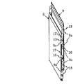
以下、図1〜図4に基づいて、この発明の実施の形態を説明する。なお、従来例と対応する部分には同一の符号を用い、実質的に同一構成部分については説明を省略するものとする。まず、図3は背中合わせに配置される2組の調整板9を互いに分離させて示した斜視図である。図3において、従来と相違するのは、上下の支持ピン13の中間に位置して、調整板9の側壁に両端がこの側壁9aから突出するバックアップピン16が支持ピン13と同じ構成で取り付けられるとともに、側壁9aは支持ピン13及びバックアップピン16の周辺を除いて切り欠かれている点である。
【0013】
調整板9の各部の寸法を従来例と同じとして、支持ピン13及びバックアップピン16の周辺に残された側壁9a部分の上下寸法は、例えば上から20mm,16mm,28mmとされ、切り欠かれた部分17の上下寸法は例えば上から45mm,40mm とされている。このような2組の調整板9は、互いに上下に位置ずれさせて背中合わせに接近配置した場合において、図4に示すように、各調整板9の側壁9a同士が相手の切り欠き部17に進入し、互い違いに抱き合うようになる。
【0014】
図1及び図2は上記した調整板9を装着した商品収納棚2の要部側面図で、図1は前後の調整板9が後退して互いに最も接近した状態を示し、図2は同じく前進した状態を示している。図1において、前後2組の調整板9は側壁9a同士が互い違いに抱き合い、この状態で一方の調整板9の側壁9aと他方の調整板9の背面との隙間を例えば0.5mm とすれば、前後の調整板9間の間隔Dは一方の側壁9aの高さに、上記隙間と他方の調整板9の板厚を加えた寸法、図示例では 8.5(7+0.5 +1 )mmとなり、従来例の14.5mmに比べて6mm(約40%)の縮小が可能になる。
【0015】
また、図1及び図2において、商品収納棚2の側板6にはバックアップピン16に対応して、溝穴14 , 15よりも溝幅の広い溝穴18が打ち抜き形成され、図1の調整板後退位置及び図2の調整板前進位置で、バックアップピン16の両端はいずれも溝穴18の垂直な縁部に当接している。これにより、調整板9は中央部分がバックアップピン16を介して商品収納棚2の側板6により背面から支えられ、商品ガイド面9bに作用する図示しない商品からの押圧力に対抗し、側壁9aが切り欠かれたことによる剛性の低下が補われる。
【0016】
なお、実施の形態では同一の2組の調整板9を互いに上下に位置ずれさせて抱き合わせる例を示したが、前後の調整板を同一の高さ位置に設置する場合には、各調整板の側壁の高さ位置を互いにずらして抱き合わせるようにする。また、実施の形態では調整板を前後2段に進退させる例を示したが、前後3段あるいはそれ以上の段数で進退させる場合にもこの発明は同様に適用することができる。更に、調整板の側壁は調整板本体から一体に折り曲げ形成する例を示したが、別体として溶接などで固着することも可能である。
【0017】
【発明の効果】
以上の通り、この発明によれば、調整板の側壁を支持ピンの周辺を除いて切り欠き、前後に隣接する商品収納室の各々の調整板を背中合わせに配置した際に、各調整板の側壁同士が互い違いに抱き合うように構成したことにより、前後の調整板の間隔を最小限に抑え、その分、商品収納棚の前後寸法を縮小して自動販売機のコンパクト化を図ることができる。また、その際、上下の支持ピンの間に位置させてバックアップピンを取り付け、このバックアップピンを商品収納棚側板の溝穴縁部に当接させることにより、側壁を切り欠いたことによる調整板の剛性の低下を補うことができる。
【図面の簡単な説明】
【図1】この発明の実施の形態を示す装置の前後2組の調整板を互いに抱き合わせた状態を示す側面図である。
【図2】図1における調整板を前進させた状態の側面図である。
【図3】図1における2組の調整板を互いに分離させた状態の斜視図である。
【図4】図3の2組の調整板を互いに抱き合わせた状態の斜視図である。
【図5】この発明が適用される自動販売機の前面扉を開放した状態の斜視図である。
【図6】図5における商品収納棚の1列分を示す斜視図である。
【図7】図6の商品収納棚における従来の商品通路幅調整装置を示すの側面図である。
【図8】図7におけるP部の拡大図である。
【図9】図8における2組の調整板を互いに分離させた状態の斜視図である。
【図10】図9の2組の調整板の互いに接近させた状態の斜視図である。
【符号の説明】
2 商品収納棚
5 商品収納室
6 側板
7 商品搬出通路
8 固定板
9 調整板
9a 側壁
10 商品
13 支持ピン
14 溝穴
15 溝穴
16 バックアップピン
17 切り欠き部
18 溝穴
T 通路幅[0001]
BACKGROUND OF THE INVENTION
The present invention relates to a vending machine provided with a product storage chamber for storing cylindrical products such as can beverages and bottled beverages in a lying position and storing them, and more particularly to an apparatus for adjusting the longitudinal width of the product delivery passage.
[0002]
[Prior art]
As the adjusting device, a device for moving the adjusting plate arranged in the product carry-out passage back and forth is conventionally known. Hereinafter, this conventional apparatus will be described. First, FIG. 5 is a perspective view showing a state in which a front door of a vending machine provided with such a product passage width adjusting device is opened. In FIG. 5, in the vending machine main body 1,
[0003]
The
[0004]
FIG. 7 is a side view of the main part showing the inside of the
[0005]
Here, a large number of
[0006]
8 is an enlarged side view showing a portion P of FIG. 7 in which two
[0007]
On the other hand, as shown in FIG. 8, a pair of upper and
[0008]
[Problems to be solved by the invention]
By the way, in the
[0009]
However, even if the two back-to-
Therefore, the present invention aims to save space by reducing the distance between the two sets of adjusting plates arranged back to back as compared with the prior art, and thus to make the vending machine more compact. is there.
[0010]
[Means for Solving the Problems]
In order to solve the above-mentioned problems, the present invention has an adjustment plate in a product carry-out passage of a product storage chamber for storing cylindrical products stacked in a horizontal position, and the adjustment plates are formed on left and right side walls that are bent to the back side. A pair of upper and lower support pins attached so that both ends protrude from the side wall are hung and supported by a slot formed in the product storage chamber side plate, and the position of the support pin in the slot is In a product passage width adjusting device of a vending machine that moves forward and backward by being turned over and adjusts the front and rear passage width of the product carry-out passage according to the diameter of the product, the side wall of the adjustment plate is attached to the side wall of the support pin. Notch except for the periphery, when the adjustment plates of the product storage chambers adjacent to each other in the front and back are arranged back to back, the side walls of the adjustment plates are configured to alternately hug each other. A backup pin that is positioned between the upper and lower support pins and that has both ends projecting from the side wall is attached to the side wall of the adjustment plate, and the groove on which the support pin is hung on the side plate corresponding to the backup pin A slot having a width wider than the hole is formed, and both ends of the backup pin of the adjustment plate abutted forward and backward are brought into contact with the edge of the slot having the wide width to support the adjustment plate from the back side. It is what you want to do. Thereby, since the side wall of each adjustment plate can enter the notch part of the other side wall, the front-rear space | interval of an adjustment plate can be reduced compared with the conventional structure which has a side wall mutually abutted.
[0011]
On the other hand , the side wall of the adjustment plate serves to increase the bending rigidity in the front-rear direction of the adjustment plate, in addition to holding the support pins. Therefore, in order to address the reduction of the rigidity that by the cutting away the side walls and is positioned between and below the support pin, both ends on the side wall of the adjusting plate is attached to the backup pins projecting from the side wall Corresponding to the backup pin, a groove having a groove width wider than the groove on which the support pin is hung is formed on the side plate of the product storage shelf, and the groove is widened forward and backward at the edge of the groove. and it is to support the adjustment plate from the back surface is brought into contact with both ends of the backup pins of the adjusting plate having. Thereby, the center part of an adjustment board can be supported from a back surface via a backup pin, and the fall of the rigidity of an adjustment board can be compensated.
[0012]
DETAILED DESCRIPTION OF THE INVENTION
Embodiments of the present invention will be described below with reference to FIGS. In addition, the same code | symbol is used for the part corresponding to a prior art example, and description is abbreviate | omitted about the substantially same component. First, FIG. 3 is a perspective view showing two sets of adjusting
[0013]
The dimension of each part of the adjusting
[0014]
FIGS. 1 and 2 are side views of the main part of the
[0015]
1 and 2, the
[0016]
In the embodiment, an example in which the same two sets of
[0017]
【The invention's effect】
As described above, according to the present invention, when the adjustment plate side walls are cut back except for the periphery of the support pins, and the adjustment plates of the product storage chambers adjacent to each other are arranged back to back, the side walls of the adjustment plates By constructing them so as to embrac each other, the distance between the front and rear adjustment plates can be minimized, and the size of the vending machine can be reduced by reducing the front and rear dimensions of the product storage shelf accordingly. At this time, a backup pin is attached between the upper and lower support pins, and the backup pin is brought into contact with the groove edge of the product storage shelf side plate so that the side wall is cut out. The decrease in rigidity can be compensated.
[Brief description of the drawings]
FIG. 1 is a side view showing a state in which two sets of front and rear adjustment plates of an apparatus showing an embodiment of the present invention are held together.
FIG. 2 is a side view of a state in which the adjustment plate in FIG. 1 is advanced.
FIG. 3 is a perspective view showing a state where two sets of adjusting plates in FIG. 1 are separated from each other.
4 is a perspective view of a state in which the two sets of adjustment plates of FIG.
FIG. 5 is a perspective view of a vending machine to which the present invention is applied with the front door opened.
6 is a perspective view showing one row of product storage shelves in FIG. 5. FIG.
7 is a side view showing a conventional product passage width adjusting device in the product storage shelf of FIG. 6. FIG.
8 is an enlarged view of a portion P in FIG.
9 is a perspective view showing a state in which the two sets of adjustment plates in FIG. 8 are separated from each other. FIG.
10 is a perspective view showing a state where the two sets of adjusting plates in FIG. 9 are brought close to each other. FIG.
[Explanation of symbols]
2
Claims (1)
前記調整板の側壁を前記支持ピンの周辺を除いて切り欠き、前後に隣接する前記商品収納室の各々の前記調整板を背中合わせに配置した際に、前記各調整板の前記側壁同士が互い違いに抱き合うように構成し、かつ上下の前記支持ピンの間に位置させて、前記調整板の側壁に両端がこの側壁から突出するバックアップピンを取り付けるとともに、このバックアップピンに対応させて前記側板に、前記支持ピンが掛けられる前記溝穴よりも溝幅の広い溝穴を形成し、この溝幅の広い溝穴の縁部に前後に進退させた前記調整板の前記バックアップピンの両端を当接させて前記調整板を背面から支えるようにしたことを特徴とする請求項1記載の自動販売機の商品通路幅調整装置。There is an adjustment plate in the product carry-out passage of the product storage room that stores cylindrical products stacked in a lying position, and this adjustment plate is attached to the left and right side walls that bend to the back side so that both ends protrude from this side wall A pair of upper and lower support pins are suspended and supported by a slot formed in the product storage chamber side plate, and the product moves forward and backward by changing the position of the support pin in the slot. In the product passage width adjusting device of the vending machine that adjusts the front and rear passage width of the carry-out passage according to the diameter size of the product,
The side walls of the adjustment plates are cut out except for the periphery of the support pins, and when the adjustment plates of the product storage chambers adjacent to each other are arranged back to back, the side walls of the adjustment plates are staggered. It is constructed so as to hold each other and is positioned between the upper and lower support pins, and attached to the side wall of the adjustment plate are backup pins whose both ends protrude from the side wall, and the side plate corresponding to the backup pin, A slot having a width wider than that of the slot on which the support pin is hung is formed, and both ends of the backup pin of the adjustment plate abutted forward and backward are brought into contact with the edge of the slot having the wide slot. 2. A product passage width adjusting device for a vending machine according to claim 1, wherein the adjusting plate is supported from the back side .
Priority Applications (1)
| Application Number | Priority Date | Filing Date | Title |
|---|---|---|---|
| JP14444199A JP3700111B2 (en) | 1999-05-25 | 1999-05-25 | Vending machine product passage width adjustment device |
Applications Claiming Priority (1)
| Application Number | Priority Date | Filing Date | Title |
|---|---|---|---|
| JP14444199A JP3700111B2 (en) | 1999-05-25 | 1999-05-25 | Vending machine product passage width adjustment device |
Publications (2)
| Publication Number | Publication Date |
|---|---|
| JP2000331235A JP2000331235A (en) | 2000-11-30 |
| JP3700111B2 true JP3700111B2 (en) | 2005-09-28 |
Family
ID=15362298
Family Applications (1)
| Application Number | Title | Priority Date | Filing Date |
|---|---|---|---|
| JP14444199A Expired - Lifetime JP3700111B2 (en) | 1999-05-25 | 1999-05-25 | Vending machine product passage width adjustment device |
Country Status (1)
| Country | Link |
|---|---|
| JP (1) | JP3700111B2 (en) |
-
1999
- 1999-05-25 JP JP14444199A patent/JP3700111B2/en not_active Expired - Lifetime
Also Published As
| Publication number | Publication date |
|---|---|
| JP2000331235A (en) | 2000-11-30 |
Similar Documents
| Publication | Publication Date | Title |
|---|---|---|
| JP4121099B2 (en) | Product display unit | |
| US7922010B2 (en) | Product management display system | |
| US7497342B2 (en) | Product management display system | |
| EP1174060A1 (en) | Product carrier tray with support member | |
| CN107103689B (en) | Automatic vending machine | |
| WO1991017939A1 (en) | Structure and method of making an article dispensing apparatus | |
| JP3700111B2 (en) | Vending machine product passage width adjustment device | |
| US4944414A (en) | Shelf assembly for vending tubular products | |
| JP4042930B2 (en) | Product display unit | |
| US3026002A (en) | Vending machine for cylindrical objects having jam preventing means | |
| JP2006252026A (en) | Commodity storage rack | |
| JP2000004998A (en) | Article display unit | |
| JPH0877445A (en) | Article storage rack device of automatic vending machine | |
| JP3826254B2 (en) | vending machine | |
| US20160343193A1 (en) | Rotary Dispensing Mechanism For Vending Machines | |
| JPS6327256Y2 (en) | ||
| JPH09154644A (en) | Small articles storage shelf | |
| EP0067242A1 (en) | Goods storage and discharge system of an automatic vending machine | |
| JP2017131393A (en) | cartridge | |
| JP3548056B2 (en) | Pusher adapter for vending machine product dispensing device | |
| US20140319089A1 (en) | Shelf and merchandise display system having stowable lane dividers | |
| KR970006654B1 (en) | Commodity storing rack for atomatic vending machine | |
| JP3921919B2 (en) | Serpentine product storage rack for vending machines | |
| JP3292812B2 (en) | Vending machine product storage device | |
| JP2598867Y2 (en) | vending machine |
Legal Events
| Date | Code | Title | Description |
|---|---|---|---|
| A977 | Report on retrieval |
Free format text: JAPANESE INTERMEDIATE CODE: A971007 Effective date: 20040827 |
|
| A131 | Notification of reasons for refusal |
Free format text: JAPANESE INTERMEDIATE CODE: A131 Effective date: 20040902 |
|
| A521 | Written amendment |
Free format text: JAPANESE INTERMEDIATE CODE: A523 Effective date: 20041025 |
|
| TRDD | Decision of grant or rejection written | ||
| A01 | Written decision to grant a patent or to grant a registration (utility model) |
Free format text: JAPANESE INTERMEDIATE CODE: A01 Effective date: 20050616 |
|
| A61 | First payment of annual fees (during grant procedure) |
Free format text: JAPANESE INTERMEDIATE CODE: A61 Effective date: 20050629 |
|
| R150 | Certificate of patent or registration of utility model |
Free format text: JAPANESE INTERMEDIATE CODE: R150 |
|
| FPAY | Renewal fee payment (event date is renewal date of database) |
Free format text: PAYMENT UNTIL: 20080722 Year of fee payment: 3 |
|
| FPAY | Renewal fee payment (event date is renewal date of database) |
Free format text: PAYMENT UNTIL: 20090722 Year of fee payment: 4 |
|
| FPAY | Renewal fee payment (event date is renewal date of database) |
Free format text: PAYMENT UNTIL: 20090722 Year of fee payment: 4 |
|
| FPAY | Renewal fee payment (event date is renewal date of database) |
Free format text: PAYMENT UNTIL: 20100722 Year of fee payment: 5 |