JP3696151B2 - Hot water heater - Google Patents
Hot water heater Download PDFInfo
- Publication number
- JP3696151B2 JP3696151B2 JP2001355965A JP2001355965A JP3696151B2 JP 3696151 B2 JP3696151 B2 JP 3696151B2 JP 2001355965 A JP2001355965 A JP 2001355965A JP 2001355965 A JP2001355965 A JP 2001355965A JP 3696151 B2 JP3696151 B2 JP 3696151B2
- Authority
- JP
- Japan
- Prior art keywords
- water
- hot water
- pipe
- heating
- pressure
- Prior art date
- Legal status (The legal status is an assumption and is not a legal conclusion. Google has not performed a legal analysis and makes no representation as to the accuracy of the status listed.)
- Expired - Fee Related
Links
Images


Description
【0001】
【発明の属する技術分野】
本発明は、熱源機とこの熱源機から温水が循環供給される放熱器を備えた温水暖房装置に関し、特に、設置後に温水回路内に給水を行う所謂水張り作業の改善を図った温水暖房装置に関するものである。
【0002】
【従来の技術】
この種の温水暖房装置に関しては、先に出願人は、特開2000−97444にて提案している。即ち出願人が先に提案した特開2000−97444では、暖房戻り継手、戻り管、プレッシャータンク、温水循環ポンプ、熱交換器、往き管、暖房往き継手及び放熱器が順次環状に接続された主回路と、前記戻り管と往き管とに跨るように設けられたバイパス回路とから成る温水回路、及び、前記熱交換器を加熱するバーナを備えた温水暖房装置において、前記プレッシャータンクに補給水ポンプを介して接続されたリザーブタンクと、このリザーブタンクに取り付けられたオーバーフロー管と、前記リザーブタンクに接続された給水管と、前記バイパス回路の上流側において前記戻り管と前記リザーブタンクとを連通する連通管と、前記バイパス回路の上流側にて前記戻り管の流路を開き、前記連通管の流路を閉じた第1の状態と、前記バイパス回路の上流側にて前記戻り管の流路を閉じ、前記連通管の流路を開いた第2の状態とに選択的に切り換える流路切換装置とを設けた構成で、温水回路全体に給水を行う水張り作業の改善を図っていた。
【0003】
【発明が解決しようとする課題】
ところで、前記特開2000−97444の温水暖房装置では、電磁弁を複数使用したり、又は、三方電磁弁を使用したりしているため、温水を生成する熱源機内部の温水回路も複雑になり、コストが高く、組立に非常に時間が掛かり、また、制御も複雑であった。
【0004】
本発明は、上述のような従来の問題点を解消したものであり、熱源機と放熱手段との間の高低差が大きくても、コストが安く、簡単な構造で、円滑に水張りを行うことができる温水暖房装置を提供することを目的とする。
【0006】
【課題を解決するための手段】
上記目的を達成するために、請求項1に記載の発明は、暖房戻り管、プレッシャーキャップを有するプレッシャータンク、温水循環ポンプ、熱交換器及び暖房往き管が順次環状に接続された機内主回路と、前記暖房戻り管と前記暖房往き管とに跨るように設けられたバイパス回路と、前記プレッシャータンクに補給水ポンプを介して接続されたリザーブタンクと、途中に補給水弁を有し、前記リザーブタンクに給水する給水管と、前記プレッシャータンク内の頂部とリザーブタンクとをプレッシャーキャップを介して連通させるプレッシャーホースと、制御手段とを有する熱源機を備え、この熱源機の暖房戻り管と暖房往き管に温水配管を介して放熱手段が接続される温水暖房装置において、前記バイパス回路の途中にはこのバイパス回路を開閉するバイパス開閉手段が設けられ、前記制御手段は、前記機内主回路の水張りが行なわれるまでは前記バイパス開閉手段を開放し、機内主回路内の水張りが完了して前記放熱手段への水張りを行なうときには前記バイパス開閉手段を閉塞し、かつ、前記補給水ポンプを停止させるように制御することを特徴とする。
【0007】
【発明の実施の形態】
以下、本発明の一実施形態を図面に基づいて説明する。
図1は本発明の一実施形態における構成を示す回路説明図、図2は制御手段の概略構成を示すブロック図、図3は温水暖房装置の動作を説明するフローチャート図である。
【0008】
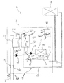
図1において、温水暖房装置Aは、熱源機1と床暖房パネル等の放熱器2(放熱手段)と外部からの給水管3と、それらを接続する配管により構成されている。
【0009】
熱源機1は、給水管3の途中に介設されて給水される水を止めたり流したりする補給水弁10と、給水管3からの水を一時貯溜し、温水温度の変化に伴う水圧変化を吸収するためのリザーブタンク11と、リザーブタンク11に貯溜された水を抜く水抜弁19(常には閉じている)を有した水抜管19Aと、リザーブタンク11内の水を水抜管19Aから分岐して送水する補給水ポンプHPと、補給水ポンプHPから送水された水を貯溜するプレッシャータンク12と、プレッシャータンク12の頂部とリザーブタンク11を接続するプレッシャーホースPHと、プレッシャータンク12に貯溜された湯水を循環する温水循環ポンプJPと、温水循環ポンプJPにより循環する湯水を加熱する熱交換器13と、この熱交換器13を温めるガスバーナなどのバーナ14と、熱交換器13から出て外部の放熱器2の温水配管OHと接続される暖房往き管15と、一端が放熱器2の温水配管OHと接続される暖房戻り管16と、暖房往き管15と暖房戻り管16の間を跨るように連通するバイパス回路17と、このバイパス回路17の途中に設けられた熱動弁17V(バイパス開閉手段)等を内蔵している。
【0010】
前記プレッシャータンク12は、それの頂部にプレッシャーキャップ12Aを設けており、このプレッシャーキャップ12Aは、温水回路O内の温水温度が低下し、暖房用温水が収縮して温水回路O内の所要水量が少なくなって、プレッシャータンク12内の圧力が−0.05〜−0.1kg/cm2まで下がると、リザーブタンク11内の水を吸引し、また、プレッシャータンク12内の水圧が温度上昇により約0.9kg/cm2まで高まると、プレッシャータンク12内の水をリザーブタンク11内に排出するように作用する。
【0011】
暖房戻り管16、プレッシャーキャップを有するプレッシャータンク12、温水循環ポンプJP、熱交換器13、暖房往き管15は熱源機1内部で順次環状に接続され機内主回路Kを構成している。そして、前記バイパス回路17の途中に設けられた熱動弁17Vが開放のときには、暖房往き管15の湯水がバイパス回路17を流れて暖房戻り管16に流入する。
【0012】
また、リザーブタンク11には水の水位を検知するためリザーブタンク水位電極SRが設けられ、プレッシャータンク12にも同様に、プレッシャータンク水位電極SPが設けられている。さらに、暖房戻り管16の他端はプレッシャータンク12内で逆J字状に成形されており、プレッシャータンク12のプレッシャータンク水位電極SPは、この逆J字状に成形された他端より上方に位置している。
【0013】
さらにまた、熱源機1には、この熱源機1の制御のすべてを司る制御器18が内蔵されている。
【0014】
放熱器2は、例えば、家屋の二階や三階の床などの熱源機1よりも高所に設置され、暖房往き管15、戻り管16と温水配管OHを介して接続することにより熱源機1と連通される。
【0015】
給水管3は、外部の水道などに直接接続され減圧弁(図示せず)などにより減圧され途中に補給水弁10を介して熱源機1と接続される。
【0016】
次に図2に示すブロック図について説明する。この制御器18には制御手段18Aであるマイクロコンピュータ(以下マイコンと記す)が搭載されており、この熱源機1の制御のすべてを司っている。このマイコン18Aの入力側には、運転スイッチSW(図1では図示せず)、リザーブタンク水位電極SR、プレッシャータンク水位電極SP等が接続されている。
【0017】
一方、マイコン18Aの出力側には、バーナ14の点火手段IG、燃料供給手段NS、空気供給手段KS(いずれも図1では図示せず)、補給水ポンプHP、温水循環ポンプJP、熱動弁17V、補給水弁10、その他種々の弁が接続されている。また、放熱器2は、マイコン18Aと放熱器制御手段HSとの間の通信により制御される。
【0018】
上述のように構成された熱源機1に水張りを行う時の温水暖房装置Aの動作を図3のフローチャート図に基づいて説明する。
【0019】
まず、熱源機1の運転スイッチSWを入れる(S1)。すると、マイコン18Aは、リザーブタンク水位電極SRによりリザーブタンク11内の水の有無を確認し(S2)、水が有ることを検知すればステップS3に移行し、水が無いことを検知すればステップS9に移行して補給水弁10が開放して、水がリザーブタンク11に給水される。ステップS3にて補給水ポンプHPが運転を開始し、リザーブタンク11に給水された水を補給水ポンプHPにより、プレッシャータンク12に送水しステップ4に移行する。また、リザーブタンク水位電極SRにて水位を検知したあと数十秒後に補給水弁10が閉塞しリザーブタンク11への給水を停止する。
【0020】
ステップS4にてマイコン18Aは、プレッシャータンク水位電極SPによりプレッシャータンク12内の水の有無を確認し、水が有ることを検知すればステップS5に移行し、水が無いことを検知すればステップS3に戻って補給水ポンプHPが運転を継続して、水をプレッシャータンク12に給水する。
【0021】
ステップS5にて温水循環ポンプJPが運転を開始し、プレッシャータンク12に給水された水を温水循環ポンプJPにより、温水回路O内に水が注入され水張りが行われる。この時、暖房往き管15と暖房戻り管16との間に設けられているバイパス回路17の熱動弁17Vは開放されている(S6)。このため、放熱器2が熱源機1よりも高所に位置していると、図1の矢印K1に示すように機内主回路K内でバイパス回路17を通って水が短絡して循環するため、熱源機1内に水張りをすばやく行うことができる。しかし、この時点では、温水循環ポンプJPの揚程性能を最大限に利用できず、放熱器2までの温水配管OH内には水が充満せずに空気が滞って、リザーブタンク11の水面も一定になり安定してしまう。
【0022】
このことは、補給水ポンプHPの性能が、温水循環ポンプJPの性能よりも圧力はあるものの流量は少なく、また、温水循環ポンプJPの性能が、補給水ポンプHPの性能よりも流量はあるものの圧力が少ないために発生する現象である。
【0023】
即ち、リザーブタンク11に給水された水を補給水ポンプHPがプレッシャータンク12に給水し、さらに温水循環ポンプJPで温水回路O内に注水する。この時、プレッシャータンク12内にある逆J字状に成形された暖房戻り管16の他端は、補給水ポンプHPの水圧Pを受けており、この水圧Pが約1.1kg/cm2まで到達する。このため、暖房戻り管16の他端からは温水配管OH内に滞っている水や空気がプレッシャータンク12内に排出されず、水は循環しない。
【0024】
さらにプレッシャーキャップ12Aが開放され、プレッシャータンク12、プレッシャーキャップ12A、プレッシャーホースPH、リザーブタンク11、補給水ポンプHPという循環回路K2にてリザーブタンク11の水面も一定になり安定してしまうのである。そして、熱動弁17Vが開放され、機内主回路K内に水が充満して循環回路K2を形成するまでの時間Tは約1〜2分間である。
【0025】
このような状態、即ち、リザーブタンク11のリザーブタンク水位電極SRが水を検知し、補給水ポンプHPが運転を開始してからT分後(S7)にマイコン18Aは、バイパス回路17の熱動弁17Vを閉塞し、且つ、補給水ポンプHPを停止する(S8)。すると、補給水ポンプHPにより、プレッシャータンク12内にある逆J字状に成形された暖房戻り管16の他端にかかっていた水圧はなくなり、プレッシャーキャップ12Aは閉じる。そして、温水循環ポンプJPの圧力により、水や滞っていた空気が暖房往き管15から温水配管OHを通り放熱器2を経て温水配管OHを通り暖房戻り管16を経て、プレッシャータンク12に排出され水が温水回路O内に充満されるのである。
【0027】
上述の構成によれば、暖房戻り管16、プレッシャーキャップ12Aを有するプレッシャータンク12、温水循環ポンプJP、熱交換器13及び暖房往き管15が順次環状に接続された機内主回路Kと、前記暖房戻り管16と前記暖房往き管15とに跨るように設けられたバイパス回路17と、前記プレッシャータンク12に補給水ポンプHPを介して接続されたリザーブタンク11と、途中に補給水弁10を有し、前記リザーブタンク11に給水する給水管3と、前記プレッシャータンク12内の頂部とリザーブタンク11とをプレッシャーキャップ12Aを介して連通させるプレッシャーホースPHと、制御手段18Aとを有する熱源機1を備え、この熱源機1の暖房戻り管16と暖房往き管15に温水配管OHを介して放熱手段2が接続される温水暖房装置Aにおいて、前記バイパス回路17の途中にはこのバイパス回路17を開閉するバイパス開閉手段17Vが設けられ、前記制御手段18Aは、前記機内主回路Kの水張りが行なわれるまでは前記バイパス開閉手段17Vを開放し、機内主回路K内の水張りが完了して前記放熱手段2への水張りを行なうときには前記バイパス開閉手段17Vを閉塞し、かつ、前記補給水ポンプHPを停止させるように制御する構成であるから、温水循環ポンプJPの揚程性能を最大限に引き出すことが可能であるのは勿論のこと、温水暖房装置Aの温水回路O内に滞っている空気を簡単な構造で早く抜くことができ、空気抜きに要する所要時間は従来に比較して大幅に短縮することができ、且つ、温水循環ポンプJPの性能を最大限に引き出して温水を循環させることができる。
【0028】
以上、実施形態に基づいて本発明を説明したが、本発明はこれに限定されるものではない。
【0030】
【発明の効果】
以上説明したように、本発明によれば、暖房戻り管、プレッシャーキャップを有するプレッシャータンク、温水循環ポンプ、熱交換器及び暖房往き管が順次環状に接続された機内主回路と、前記暖房戻り管と前記暖房往き管とに跨るように設けられたバイパス回路と、前記プレッシャータンクに補給水ポンプを介して接続されたリザーブタンクと、途中に補給水弁を有し、前記リザーブタンクに給水する給水管と、前記プレッシャータンク内の頂部とリザーブタンクとをプレッシャーキャップを介して連通させるプレッシャーホースと、制御手段とを有する熱源機を備え、この熱源機の暖房戻り管と暖房往き管に温水配管を介して放熱手段が接続される温水暖房装置において、前記バイパス回路の途中にはこのバイパス回路を開閉するバイパス開閉手段が設けられ、前記制御手段は、前記機内主回路の水張りが行なわれるまでは前記バイパス開閉手段を開放し、機内主回路内の水張りが完了して前記放熱手段への水張りを行なうときには前記バイパス開閉手段を閉塞し、かつ、前記補給水ポンプを停止させるように制御する構成であるから、温水循環ポンプの揚程性能を最大限に引き出すことが可能である上、温水暖房装置の循環回路内に滞っている空気を一層早く抜くことができ、しかも、空気抜きに要する所要時間を従来に比較して大幅に短縮することが可能になり、更に、温水循環ポンプの性能を最大限に引き出して温水を循環させることができる。
【図面の簡単な説明】
【図1】この発明の一実施の形態を示す温水暖房装置の構成図である。
【図2】この発明の一実施の形態を示す温水暖房装置のブロック図である。
【図3】この発明の一実施の形態を示す温水暖房装置のフローチャート図である。
【符号の説明】
A 温水暖房装置
1 熱源機
2 放熱器(放熱手段)
3 給水管
10 補給水弁
11 リザーブタンク
12 プレッシャータンク
12A プレッシャーキャップ
13 熱交換器
15 暖房往き管
16 暖房戻り管
17 バイパス回路
17V 熱動弁(バイパス開閉手段)
18A マイコン(制御手段)
JP 温水循環ポンプ
HP 補給水ポンプ
PH プレッシャーホース
K 機内主回路
OH 温水配管[0001]
BACKGROUND OF THE INVENTION
The present invention relates to a hot water heating apparatus including a heat source device and a radiator to which hot water is circulated and supplied from the heat source device, and more particularly to a hot water heating apparatus that improves so-called water filling work for supplying water into a hot water circuit after installation. Is.
[0002]
[Prior art]
With regard to this type of hot water heater, the applicant previously proposed in Japanese Patent Application Laid-Open No. 2000-97444. That is, in Japanese Patent Application Laid-Open No. 2000-97444 previously proposed by the applicant, a heating return joint, a return pipe, a pressure tank, a hot water circulation pump, a heat exchanger, a forward pipe, a heating forward joint, and a radiator are sequentially connected in a ring shape. A hot water circuit comprising a circuit and a bypass circuit provided so as to straddle the return pipe and the forward pipe, and a hot water heating apparatus comprising a burner for heating the heat exchanger, wherein a replenishment water pump is provided in the pressure tank. A reserve tank connected to the reserve tank, an overflow pipe attached to the reserve tank , a water supply pipe connected to the reserve tank , and the return pipe and the reserve tank on the upstream side of the bypass circuit. A first state in which the flow path of the return pipe is opened on the upstream side of the communication pipe and the bypass circuit, and the flow path of the communication pipe is closed; In a configuration provided with a flow path switching device for selectively switching to the second state in which the flow path of the return pipe is closed on the upstream side of the bypass circuit and the flow path of the communication pipe is opened, The water filling work for supplying water was improved.
[0003]
[Problems to be solved by the invention]
Meanwhile, the Japanese Unexamined water heating device of 2000-97444 is or use multiple solenoid valve, or, because of or using a three-way solenoid valve, the hot water circuit of the internal heat source apparatus for generating a hot water becomes complicated The cost is high, the assembly time is very long, and the control is complicated.
[0004]
The present invention solves the above-described conventional problems, and even if the height difference between the heat source device and the heat radiating means is large, the cost is low, and the water filling is smoothly performed with a simple structure. An object of the present invention is to provide a hot water heating apparatus capable of performing the above.
[0006]
[Means for Solving the Problems]
In order to achieve the above object, the invention described in
[0007]
DETAILED DESCRIPTION OF THE INVENTION
Hereinafter, an embodiment of the present invention will be described with reference to the drawings.
FIG. 1 is a circuit explanatory diagram showing a configuration in one embodiment of the present invention, FIG. 2 is a block diagram showing a schematic configuration of a control means, and FIG. 3 is a flowchart for explaining the operation of a hot water heater.
[0008]
In FIG. 1, the hot water heating apparatus A is comprised by the
[0009]
The
[0010]
The
[0011]
The
[0012]
The reserve tank 11 is provided with a reserve tank water level electrode SR for detecting the water level, and the
[0013]
Furthermore, the
[0014]
The
[0015]
The
[0016]
Next, the block diagram shown in FIG. 2 will be described. The
[0017]
On the other hand, on the output side of the
[0018]
The operation of the hot water heating apparatus A when performing water filling on the
[0019]
First, the operation switch SW of the
[0020]
In step S4, the
[0021]
In step S5, the hot water circulation pump JP starts operation, and water supplied to the
[0022]
This is because the performance of the makeup water pump HP is less pressure than the performance of the hot water circulation pump JP, but the flow rate is small, and the performance of the warm water circulation pump JP is greater than the performance of the makeup water pump HP. This is a phenomenon that occurs because the pressure is low.
[0023]
That is, the water supplied to the reserve tank 11 is supplied to the
[0024]
Further, the
[0025]
In such a state, that is, T minutes after the reserve tank water level electrode SR of the reserve tank 11 detects water and the makeup water pump HP starts operation (S7), the
[0027]
According to the above-described configuration, the main circuit K in which the
[0028]
As mentioned above, although this invention was demonstrated based on embodiment, this invention is not limited to this.
[0030]
【The invention's effect】
As described above, according to the present invention, a heating return pipe, a pressure tank having a pressure cap, a hot water circulation pump, a heat exchanger, and a heating forward pipe are sequentially connected in an annular manner, and the heating return pipe And a bypass circuit provided so as to straddle the heating forward pipe, a reserve tank connected to the pressure tank via a makeup water pump, and a makeup water valve in the middle of the supply tank for supplying water to the reserve tank A heat source having a pipe, a pressure hose connecting the top of the pressure tank and the reserve tank via a pressure cap, and a control means, and a hot water pipe is provided in the heating return pipe and the heating outgoing pipe of the heat source machine. In the hot water heating apparatus to which the heat dissipating means is connected via, a bypass that opens and closes the bypass circuit in the middle of the bypass circuit Opening / closing means is provided, and the control means opens the bypass opening / closing means until the main circuit in the machine is filled with water, and when the filling in the main circuit in the machine is completed and the heat radiating means is filled with water, the control means Since the bypass opening and closing means is closed and the makeup water pump is controlled to stop , it is possible to maximize the head performance of the hot water circulation pump, and in the circulation circuit of the hot water heating device. In addition, it is possible to extract the air remaining in the air more quickly, and it is possible to significantly reduce the time required for air removal compared to the conventional method. Can be circulated.
[Brief description of the drawings]
FIG. 1 is a configuration diagram of a hot water heater showing an embodiment of the present invention.
FIG. 2 is a block diagram of a hot water heating apparatus showing an embodiment of the present invention.
FIG. 3 is a flowchart of a hot water heating apparatus showing an embodiment of the present invention.
[Explanation of symbols]
A
3
18A Microcomputer (control means)
JP Hot water circulation pump HP Replenishment water pump PH Pressure hose K In-machine main circuit OH Hot water piping
Claims (1)
前記バイパス回路の途中にはこのバイパス回路を開閉するバイパス開閉手段が設けられ、前記制御手段は、前記機内主回路の水張りが行なわれるまでは前記バイパス開閉手段を開放し、機内主回路内の水張りが完了して前記放熱手段への水張りを行なうときには前記バイパス開閉手段を閉塞し、かつ、前記補給水ポンプを停止させるように制御することを特徴とする温水暖房装置。A heating return pipe, a pressure tank having a pressure cap, a hot water circulation pump, a heat exchanger, and a heating forward pipe are provided so as to straddle the in-machine main circuit, and the heating return pipe and the heating forward pipe. A bypass circuit, a reserve tank connected to the pressure tank via a makeup water pump, a supplementary water valve in the middle, a water supply pipe for supplying water to the reserve tank, a top portion in the pressure tank, and a reserve tank In a hot water heating apparatus, comprising a heat source device having a pressure hose that communicates with a pressure cap through a pressure cap, and a control means, and a heat radiating means connected to a heating return pipe and a heating forward pipe of the heat source machine via a hot water pipe ,
A bypass opening / closing means for opening and closing the bypass circuit is provided in the middle of the bypass circuit, and the control means opens the bypass opening / closing means until the main circuit in the machine is filled with water. The hot water heating apparatus is controlled to close the bypass opening / closing means and stop the make-up water pump when the heat radiation means is filled with water.
Priority Applications (1)
| Application Number | Priority Date | Filing Date | Title |
|---|---|---|---|
| JP2001355965A JP3696151B2 (en) | 2001-11-21 | 2001-11-21 | Hot water heater |
Applications Claiming Priority (1)
| Application Number | Priority Date | Filing Date | Title |
|---|---|---|---|
| JP2001355965A JP3696151B2 (en) | 2001-11-21 | 2001-11-21 | Hot water heater |
Publications (2)
| Publication Number | Publication Date |
|---|---|
| JP2003161452A JP2003161452A (en) | 2003-06-06 |
| JP3696151B2 true JP3696151B2 (en) | 2005-09-14 |
Family
ID=19167576
Family Applications (1)
| Application Number | Title | Priority Date | Filing Date |
|---|---|---|---|
| JP2001355965A Expired - Fee Related JP3696151B2 (en) | 2001-11-21 | 2001-11-21 | Hot water heater |
Country Status (1)
| Country | Link |
|---|---|
| JP (1) | JP3696151B2 (en) |
-
2001
- 2001-11-21 JP JP2001355965A patent/JP3696151B2/en not_active Expired - Fee Related
Also Published As
| Publication number | Publication date |
|---|---|
| JP2003161452A (en) | 2003-06-06 |
Similar Documents
| Publication | Publication Date | Title |
|---|---|---|
| JP4893070B2 (en) | Return hot water recovery method and hot water supply system | |
| JP4023139B2 (en) | Hybrid water heater | |
| JP2005061711A (en) | Exhaust heat recovering water heater | |
| AU784554B2 (en) | Engine cooling system with two thermostats | |
| JP5793450B2 (en) | Heat pump heat source system | |
| KR20130061987A (en) | A expansion tank equipped a warm-up function of a boiler and a boiler-system using the same | |
| JP3696151B2 (en) | Hot water heater | |
| JP3869804B2 (en) | Heat pump water heater / heater | |
| JP5567863B2 (en) | Heat supply equipment | |
| US20220205682A1 (en) | Smart circulation control instantaneous-heating storage heat exchanger | |
| JP2001248913A (en) | Storage type hot water supply apparatus | |
| JP4550009B2 (en) | Hot water supply system with reheating function | |
| JP2000097444A (en) | Hot water heater | |
| JP2000097443A (en) | Hot water heater | |
| JP6152659B2 (en) | Water heater | |
| JP3702055B2 (en) | Heat source machine for hot water heater | |
| JP2019117005A (en) | Hot water supply heating system | |
| JP7064694B2 (en) | Hot water storage and hot water supply device | |
| JP3810161B2 (en) | Combustion device | |
| JP3763900B2 (en) | Combustion device | |
| JP2512694B2 (en) | Bathroom heating drying system | |
| KR980009069U (en) | Automatic heating water refilling device for hot water boiler | |
| JP4099085B2 (en) | Cogeneration system | |
| JP4059602B2 (en) | Heat medium supply system | |
| JP2008045850A (en) | Hot water supply device |
Legal Events
| Date | Code | Title | Description |
|---|---|---|---|
| A621 | Written request for application examination |
Free format text: JAPANESE INTERMEDIATE CODE: A621 Effective date: 20040405 |
|
| A711 | Notification of change in applicant |
Free format text: JAPANESE INTERMEDIATE CODE: A712 Effective date: 20040422 |
|
| A521 | Written amendment |
Free format text: JAPANESE INTERMEDIATE CODE: A821 Effective date: 20040422 |
|
| A977 | Report on retrieval |
Free format text: JAPANESE INTERMEDIATE CODE: A971007 Effective date: 20050413 |
|
| A131 | Notification of reasons for refusal |
Free format text: JAPANESE INTERMEDIATE CODE: A131 Effective date: 20050510 |
|
| A521 | Written amendment |
Free format text: JAPANESE INTERMEDIATE CODE: A523 Effective date: 20050517 |
|
| TRDD | Decision of grant or rejection written | ||
| A01 | Written decision to grant a patent or to grant a registration (utility model) |
Free format text: JAPANESE INTERMEDIATE CODE: A01 Effective date: 20050614 |
|
| A61 | First payment of annual fees (during grant procedure) |
Free format text: JAPANESE INTERMEDIATE CODE: A61 Effective date: 20050628 |
|
| FPAY | Renewal fee payment (event date is renewal date of database) |
Free format text: PAYMENT UNTIL: 20080708 Year of fee payment: 3 |
|
| FPAY | Renewal fee payment (event date is renewal date of database) |
Free format text: PAYMENT UNTIL: 20090708 Year of fee payment: 4 |
|
| FPAY | Renewal fee payment (event date is renewal date of database) |
Free format text: PAYMENT UNTIL: 20090708 Year of fee payment: 4 |
|
| FPAY | Renewal fee payment (event date is renewal date of database) |
Free format text: PAYMENT UNTIL: 20100708 Year of fee payment: 5 |
|
| FPAY | Renewal fee payment (event date is renewal date of database) |
Free format text: PAYMENT UNTIL: 20110708 Year of fee payment: 6 |
|
| FPAY | Renewal fee payment (event date is renewal date of database) |
Free format text: PAYMENT UNTIL: 20120708 Year of fee payment: 7 |
|
| FPAY | Renewal fee payment (event date is renewal date of database) |
Free format text: PAYMENT UNTIL: 20120708 Year of fee payment: 7 |
|
| S111 | Request for change of ownership or part of ownership |
Free format text: JAPANESE INTERMEDIATE CODE: R313115 |
|
| FPAY | Renewal fee payment (event date is renewal date of database) |
Free format text: PAYMENT UNTIL: 20120708 Year of fee payment: 7 |
|
| R350 | Written notification of registration of transfer |
Free format text: JAPANESE INTERMEDIATE CODE: R350 |
|
| FPAY | Renewal fee payment (event date is renewal date of database) |
Free format text: PAYMENT UNTIL: 20130708 Year of fee payment: 8 |
|
| LAPS | Cancellation because of no payment of annual fees |