JP3692251B2 - Engine with fuel injection nozzle - Google Patents
Engine with fuel injection nozzle Download PDFInfo
- Publication number
- JP3692251B2 JP3692251B2 JP05814999A JP5814999A JP3692251B2 JP 3692251 B2 JP3692251 B2 JP 3692251B2 JP 05814999 A JP05814999 A JP 05814999A JP 5814999 A JP5814999 A JP 5814999A JP 3692251 B2 JP3692251 B2 JP 3692251B2
- Authority
- JP
- Japan
- Prior art keywords
- fuel injection
- injection nozzle
- fuel
- hole
- head cover
- Prior art date
- Legal status (The legal status is an assumption and is not a legal conclusion. Google has not performed a legal analysis and makes no representation as to the accuracy of the status listed.)
- Expired - Fee Related
Links
Images


Description
【0001】
【発明の属する技術分野】
本発明は、燃料噴射ノズルをヘッドカバー内に配置したエンジンに関するものである。
【0002】
【従来の技術】
上記エンジンは、例えば次のように構成してある。
即ち、図8に示すように、燃料噴射ノズル(13)の高圧燃料受入部(14)に対向させてヘッドカバー(5)に貫通孔(19)を設け、燃料噴射ポンプに接続した高圧燃料管(12)の先端の接続具(80)を、上記貫通孔(19)からヘッドカバー(5)内へ挿入して、上記高圧燃料受入部(14)に螺着してある。また、上記貫通孔(19)と上記高圧燃料受入部(14)との間を気密に封止するため、貫通孔(19)の内周面と高圧燃料受入部(14)の外周面との間にシール部材(81)を設けてある。
そして、燃料噴射ポンプで加圧した燃料を、上記高圧燃料管(12)を介して燃料噴射ノズル(13)へ圧送し、その燃料噴射ノズル(13)から燃焼室内に噴射するようにしてある。
【0003】
【発明が解決しようとする課題】
上記燃料噴射型エンジンにおいて、ヘッドカバー(5)内の動弁装置のメンテナンスなどを行う場合には、上記高圧燃料管(12)を上記高圧燃料受入部(14)から取り外したのち、ヘッドカバー(5)をシリンダヘッドから取り外すことになる。
ところが、上記シール部材(81)が、上記貫通孔(19)に内嵌した状態でヘッドカバー(5)内の上記高圧燃料受入部(14)の外周面まで延びているため、ヘッドカバー(5)の取り外しの際にシール部材(81)が上記高圧燃料受入部(14)に引っ掛ってしまう。このため、シール部材(81)を上記貫通孔(19)から取り外さなければならず、その分だけ、ヘッドカバー(5)の着脱操作の際に手間がかかっていた。
【0004】
本発明は、ヘッドカバーの気密性を維持できながら、ヘッドカバーを着脱する際の手間を低減できる燃料噴射ノズルを備えたエンジンを提供することを目的とする。また、本発明は、燃料噴射ノズルの高圧燃料受入部をヘッドカバーの貫通孔に対して適正な位置に設定できて、シール部材の封止作用を確実に得られるようにすることを目的とする。
【0005】
【課題を解決するための手段】
[請求項1の発明]
請求項1の発明は、上記の目的を達成するために、例えば図1と図2とに示すように、次のように構成したものである。
燃料噴射ノズル(13)をヘッドカバー(5)内に配置し、ヘッドカバー(5)に貫通孔(19)を設けて、貫通孔(19)を燃料噴射ノズル(13)に凸設した高圧燃料受入部(14)に対向させ、高圧燃料管(12)の先端に設けた接続具(20)を貫通孔(19)からヘッドカバー(5)内へ挿入して、接続具(20)を高圧燃料受入部(14)に外嵌固定した燃料噴射ノズルを備えたエンジンにおいて、
【0006】
貫通孔(19)の内周面と接続具(20)の外周面との間を気密状に封止するカバー側シール部材(21)を設け、カバー側シール部材(21)の燃料噴射ノズル(13)側の先端部(21a)が高圧燃料受入部(14)の先端よりもヘッドカバー(5)側へ位置するように構成し、接続具(20)の内周面と高圧燃料受入部(14)の外周面との間を気密状に封止する噴射器側シール部材(22)を設け、例えば図1から図5に示すように、支点部 (51) 、力点部 (53) 、作用点部 (52) を備えた梃子(46)と押さえボルト(47)とを有するノズル押さえ具(48)を設け、その梃子(46)を受け止めるストッパ(49)を設けることにより、押さえボルト(47)に設けた押圧部(54)で梃子(46)の力点部(53)を押圧して、支点部 (51) を中心として揺動する梃子(46)の作用点部(52)で燃料噴射ノズル(13)を、シリンダヘッド(3)に設けたノズル挿入孔(33)に押し込んだ際には、支点部 (51) を中心として揺動する梃子(46)がストッパ(49)で受け止められるように構成し、押さえボルト(47)の締め込み作業時に、燃料噴射ノズル(13)の押し込み力が強くなり過ぎることが防止されるようにしたものである。
【0008】
[請求項2の発明]
請求項2の発明は、上記請求項1の発明の構成において、さらに次のように構成したものである。
ストッパ(49)で梃子(46)の力点部(53)を受け止めるように構成したものである。
【0009】
[請求項3の発明]
請求項3の発明は、上記請求項1又は2の発明の構成において、さらに次のように構成したものである。
梃子(46)の作用点部(52)によって燃料噴射ノズル(13)を廻り止めした状態で、その作用点部(52)で燃料噴射ノズル(13)を押圧するように構成したものである。
【0010】
【発明の作用及び効果】
[請求項1]
上記請求項1の発明は、次の作用・効果を奏する。
高圧燃料管(12)の先端側を貫通孔(19)からヘッドカバー(5)内へ挿入し、高圧燃料管(12)の先端の接続具(20)を燃料噴射ノズル(13)の高圧燃料受入部(14)に外嵌固定することにより、燃料噴射ノズル(13)からシリンダ(30)内へ燃料噴射が可能になる。
【0011】
そして、上記接続具(20)をヘッドカバー(5)内へ挿入したときには、カバー側シール部材(21)が、貫通孔(19)の内周面と接続具(20)の外周面との間を気密状に封止するので、ヘッドカバー(5)内に飛散しているオイルミストが貫通孔(19)を通ってヘッドカバー(5)外へ漏洩することが防止される。そのうえ、噴射器側シール部材(22)によって、上記ヘッドカバー(5)内のオイルミストが接続具(20)と高圧燃料受入部(14)との隙間を通ってヘッドカバー(5)外へ漏洩することが防止される。これにより、ヘッドカバー(5)内に飛散しているオイルミストがヘッドカバー(5)外へ漏洩することが確実に防止される。さらに、噴射器側シール部材(22)によって、燃料が接続具(20)と上記高圧燃料受入部(14)との隙間を通ってヘッドカバー(5)内へ漏洩することが防止される。
【0012】
かかる効果を奏する構成であるうえ、カバー側シール部材(21)は、燃料噴射ノズル(13)側の先端部(21a)が上記高圧燃料受入部(14)の先端よりもヘッドカバー(5)側へ位置するので、メンテナンスなどの際でのヘッドカバー(5)の着脱に先立ってカバー側シール部材(21)を貫通孔(19)から取り外さなくても、上記ヘッドカバー(5)の着脱の際にカバー側シール部材(21)が上記高圧燃料受入部(14)に引っ掛かることがない。つまり、ヘッドカバー(5)の着脱の際にカバー側シール部材(21)を貫通孔(19)から取り外さなくても済む分だけ、ヘッドカバー(5)の着脱の際の手間が低減される。
【0013】
上記請求項1の発明は、さらに次の作用・効果を奏する。
押さえボルト(47)の締め込みによる梃子(46)の動きは、その梃子(46)がストッパ(49)に受け止められることにより停止する。このため、燃料噴射ノズル(13)と梃子(46)とストッパ(49)の寸法精度がある程度確保されれば、押さえボルト(47)の締め込み作業時に、燃料噴射ノズル(13)の押し込み力が強くなり過ぎることが防止され、その押し込み力によって生じる燃料噴射ノズル(13)の変形を防止できる。
【0014】
そして、上記押さえボルト(47)の締め込み作業によって燃料噴射ノズル(13)が変形しない分だけ、燃料噴射ノズル(13)の高圧燃料受入部(14)を貫通孔(19)に対して正確な位置で対向させることができる。これにより、上記高圧燃料受入部(14)に固定した接続具(20)が貫通孔(19)に対する適正な位置からずれて、カバー側シール部材(21)の封止作用が低減することを防止できる。
【0015】
[請求項2]
上記請求項2の発明は、上記請求項1の発明の作用・効果に加え、さらに次の作用・効果を奏する。
ストッパ(49)で梃子(46)の力点部(53)以外の部分が受け止められることによる、梃子(46)の歪みを防止でき、その分だけ、燃料噴射ノズル(13)への梃子(46)の押し込み力を適正にすることができる。従って、押さえボルト(47)の締め込み作業による燃料噴射ノズル(13)の変形を確実に防止できて、燃料噴射ノズル(13)の高圧燃料受入部(14)を貫通孔(19)に対してより正確な位置で対向させることができる。これにより、上記接続具(20)が貫通孔(19)に対する適正な位置からずれることを低減でき、カバー側シール部材(21)の封止作用を確実に確保できる。
【0016】
[請求項3]
上記請求項3の発明は、上記請求項1又は2の発明の作用・効果に加え、さらに次の作用・効果を奏する。
梃子(46)の作用点部(52)によって燃料噴射ノズル(13)を廻り止めしたことにより、燃料噴射ノズル(13)の高圧燃料受入部(14)を貫通孔(19)に対してより正確な位置で対向させることができ、これによって上記接続具(20)が貫通孔(19)に対する適正な位置から横方向へずれることを低減できて、カバー側シール部材(21)の封止作用をより確実に確保できる。
【0017】
【発明の実施の形態】
以下、本発明にかかる燃料噴射型エンジンの実施の一形態について図1から図6を用いて説明する。
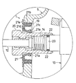
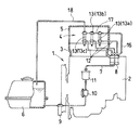
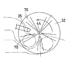
図1は上記燃料噴射型エンジンのシリンダヘッド部分の要部を示す縦断面図、図2は図1中のII部拡大図、図3は上記燃料噴射型エンジンの燃料供給系を示す概略構成図である。図4(A)は図1中のA−A線矢視断面図、図4(B)は図1中のB−B線矢視断面図、図4(C)は図1中のC−C線矢視断面図、図4(D)は図1中のD−D線矢視断面図である。図5は上記エンジンにかかるヘッドカバーを取り外した状態の要部を示す平面図、図6は上記エンジンにかかるグロープラグと燃料噴射軸線の向きとを説明する模式図である。
【0018】
上記エンジン(1)のシリンダブッロック(2)の上側にはシリンダヘッド(3)を組み付けてあり、上記シリンダブッロック(2)内のシリンダ(30)にはピストン(31)を上下動可能に内嵌してある。上記ピストン(31)の頂面にはキャビティ(32)を形成してある。
上記シリンダヘッド(3)の上側にはヘッドカバー(5)を取り付けてあり、そのヘッドカバー(5)内に動弁装置(4)と吸排気弁(26)(27)[図5参照]と燃料噴射ノズル(13)とを配置してある。そして、燃料噴射ノズル(13)を、シリンダヘッド(3)に設けたノズル挿入孔(33)に挿入した状態で、燃料噴射ノズル(13)の先端部をシリンダ(30)内へ突入させてある。なお、この実施の形態では、3気筒の燃料噴射型エンジンを例示してあり、気筒毎に燃料噴射ノズル(13a)(13b)(13c)をそれぞれ配置してある[図3参照]。
【0019】
また、上記シリンダヘッド(3)にはプラグ挿入孔(34)を設けてあり、そのプラグ挿入孔(34)にグロープラグ(35)を螺着させた状態で、グロープラグ(35)の先端部をシリンダ(30)内へ突入させてある。なお、燃料噴射ノズル(13)は、シリンダ中心軸線(44)と平行な向きに設定されており、グロープラグ(35)は、上記シリンダ中心軸線(44)に対して傾斜させてある[図6参照]。
【0020】
上記燃料噴射ノズル(13)の側面部分には高圧燃料受入部(14)を凸設してあり、その高圧燃料受入部(14)には高圧燃料管(12)の一端側を接続してある。その高圧燃料管(12)の他端側には、図3に示すように、燃料噴射ポンプ(8)を接続してあり、その燃料噴射ポンプ(8)と燃料タンク(6)とを燃料供給路(7)で連通してある。その燃料供給路(7)には燃料タンク(6)側から順に燃料フィルタ(9)、フィードポンプ(10)及び補助フィルタ(11)を設けてある。
また、上記ヘッドカバー(5)には貫通孔(19)を設けてあり、その貫通孔(19)を上記燃料噴射ノズル(13)の高圧燃料受入部(14)に対向させてある。そして、上記高圧燃料管(12)の先端部に取り付けた接続具(20)を上記貫通孔(19)からヘッドカバー(5)内へ挿入して、上記接続具(20)を上記高圧燃料受入部(14)に螺着してある[図2参照]。
【0021】
そして、上記燃料タンク(6)の燃料は、上記燃料フィルタ(9)及び補助フィルタ(11)で濾過されて上記燃料内の塵芥が除去されたのち、フィードポンプ(10)で燃料噴射ポンプ(8)に送られる。その燃料は、燃料噴射ポンプ(8)によって加圧された状態で上記高圧燃料管(12)を介して燃料噴射ノズル(13)に圧送され、その燃料噴射ノズル(13)から燃焼室内に向けて噴射される。
【0022】
上記貫通孔(19)と上記接続具(20)との間、及び接続具(20)と上記高圧燃料受入部(14)との間は、図2に示すように、次の構成により気密に封止されている。
即ち、上記貫通孔(19)の内周面と上記接続具(20)の外周面との間にはカバー側シール部材(21)を設けてあり、そのカバー側シール部材(21)の燃料噴射ノズル(13)側の先端部(21a)が、上記高圧燃料受入部(14)の先端よりもヘッドカバー(5)側へ位置するように構成してある。
上記カバー側シール部材(21)は、上記貫通孔(19)の内周面に圧接する貫通孔側封止部(21b)と、上記接続具(20)の外周面に圧接する接続具側封止部(21c)とを有しており、さらに、それらの貫通孔側封止部(21b)と接続具側封止部(21c)との間に弾性変形可能な弾性部(21d)を介在させてある。なお、上記カバー側シール部材(21)は心材(21e)によって保形されている。
【0023】
また、上記接続具(20)の内周面と上記高圧燃料受入部(14)の外周面との間には噴射器側シール部材(22)を設けてある。つまり、高圧燃料受入部(14)の外周面には溝(23)を周設してあり、その溝(23)内に上記噴射器側シール部材(22)を配置してある。なお、例えば図7に示すように、接続具(20)の内周面に周設した溝(24)に上記噴射器側シール部材(22)を配置してもよい。
【0024】
そして、上記カバー側シール部材(21)によって、ヘッドカバー(5)内に飛散しているオイルミストが上記貫通孔(19)を通ってヘッドカバー(5)外へ漏洩することが防止される。また、上記噴射器側シール部材(22)によって、ヘッドカバー(5)内に飛散しているオイルミストが接続具(20)と高圧燃料受入部(14)との隙間を通ってヘッドカバー(5)外へ漏洩することが防止されるとともに、燃料が上記接続具(20)と高圧燃料受入部(14)との隙間を通ってヘッドカバー(5)内へ漏洩することが防止される。
なお、各燃料噴射ノズル(13)の上端部分には、オーバーフロー燃料出口(15)を形成してあり、そのオーバーフロー燃料出口(15)には、図3に示すように、オーバーフロー燃料返送路(18)を介して燃料タンク(6)を連通してある。また、燃料噴射ポンプ(8)と各燃料噴射ノズル(13a)(13b)(13c)とをオーバーフロー燃料通路(16)(17)で連通してある。
【0025】
次に、上記動弁装置(4)の詳細な構成について説明する。
即ち、上記シリンダヘッド(3)にはロッカアームブラケット(37)を載置してあり、そのロッカアームブラケット(37)に固定ボルト(38)を貫通させた状態で、その固定ボルト(38)をシリンダヘッド(3)に螺着してある。そして、上記固定ボルト(38)のボルト頭部でロッカアームブラケット(37)を押さえ込むことで、ロッカアームブラケット(37)をシリンダヘッド(3)に固定してある。
【0026】
また、ロッカアームブラケット(37)にはロッカアーム枢軸(39)を貫通した状態で固定してあり、そのロッカアーム枢軸(39)にはロッカアーム(40)を揺動自在に取り付けてある。そのロッカアーム(40)の入力部(40a)を、動弁カム[図示せず]に連動するプッシュロッド(41)に接当させ、ロッカアーム(40)の出力部(40b)をバルブブリッジ(42)に接当させてある[図5参照]。そして、上記動弁カムでプッシュロッド(41)とロッカアーム(40)とを順に介して吸排気弁(26)(27)を開閉するようになっている。
なお、図5に示すように、シリンダ毎に一対の吸気弁(26)(26)と一対の排気弁(27)(27)とを配置してあり、その一対の吸気弁(26)(26)の弁軸頭部間に1本のバルブブリッジ(42)を架設し、上記の一対の排気弁(27)(27)の弁軸頭部間に1本のバルブブリッジ(42)を架設してある。
【0027】
上記燃料噴射ノズル(13)は、次の構成によりノズル挿入孔(33)内に押し込まれて、シリンダヘッド(3)に固定される。
即ち、梃子(46)と押さえボルト(47)とを有するノズル押さえ具(48)をロッカアームブラケット(37)に設けてある。その梃子(46)は、板状に形成されており、その一端[図1中では右側]で支点部(51)を、他端[図1中では左側]で作用点部(52)を、中間部で力点部(53)を構成してある。また、上記押さえボルト(47)の下端部をシリンダヘッド(3)に螺着してあり、その押さえボルト(47)の上端部にナット(54)を螺着してある。
【0028】
なお、ロッカアームブラケット(37)には、図4(D)に示すように、係止溝(50)を設けてあり、その係止溝(50)に押さえボルト(47)の周面の一部を係合することで、押さえボルト(47)と固定ボルト(38)とによってロッカアームブラケット(37)を廻り止めしている。つまり、押さえボルト(47)でロッカアームブラケット(37)の廻り止めが強化され、これに起因する吸排気弁(26)(27)の開閉タイミングの狂いが抑制され、これによって適正な吸排気タイミングを正確に設定することができ、良好な燃焼を実現できる。
【0029】
また、ロッカアームブラケット(37)の上部には、図4(A)(C)に示すように、ストッパ(49)を設けてある。そのストッパ(49)は、ロッカアームブラケット(37)の燃料噴射ノズル(13)側の端部[図4(A)中では左側]から押さえボルト(47)の両側[図4(C)中では左右両側]に沿って立ち上げられており、そのストッパ(49)で上記梃子(46)の力点部(53)を受け止めるようにしてある。
一方、燃料噴射ノズル(13)の軸部(28)の両側位置[図4(B)中では左右位置]には受圧面(58)(58)を設けてあり、その受圧面(58)(58)に上記梃子(46)の作用点部(52)が接当するようにしてある。
【0030】
そして、上記押さえボルト(47)に対するナット(54)の締結力で、上記梃子(46)の力点部(53)が押圧されることで、上記梃子(46)の作用点部(52)で燃料噴射ノズル(13)の受圧面(58)(58)が押圧され、これによって燃料噴射ノズル(13)がノズル挿入孔(33)内に押し込まれる。また、図1に示すように、上記作用点部(52)は上記受圧面(58)に向けて凸状の円弧面に形成されており、上記作用点部(52)の昇降によって、上記受圧面(58)の受圧点がずれるのを抑制している。なお、燃料噴射ノズル(13)は、ノズル挿入孔(33)の奥端部に銅パッキン(61)を介して受け止められる。
【0031】
また、上記梃子(46)の作用点部(52)側[図4(A)中では左側]には長孔(60)を設けてあり、その長孔(60)に、上記燃料噴射ノズル(13)の偏平な軸部(28)を挿通してある。この長孔(60)と上記軸部(28)との嵌合によって、燃料噴射ノズル(13)が廻り止めされ、図6に示すように、上記シリンダ中心軸線(44)と平行な向きに見て燃料噴射ノズル(13)の隣合う一対の燃料噴射軸線(70)(70)が、グロープラグ(35)の両脇を通過する状態を確実に維持できる。これにより、グロープラグ(35)への噴射燃料の直撃が起こりにくくなって、これに起因するグロープラグ(35)の焼損を抑制できる。なお、上記長孔(60)を設けることに代えて、上記梃子(46)の作用点部(52)側を、例えば二股状に形成し、その二股の作用点部(52)側の間に上記燃料噴射ノズル(13)の軸部(28)を嵌合して、燃料噴射ノズル(13)を廻り止めしてもよい。
【0032】
上記ノズル押さえ具(48)は、燃料噴射ノズル(13)をシリンダヘッド(3)に固定する機能に加え、さらに次のような機能を備えている。
即ち、上記梃子(46)の支点部(51)をロッカアームブラケット(37)の上端部に載置して接当してあり、その支点部(51)でロッカアームブラケット(37)を押さえ込んでいる。また、上記ロッカアームブラケット(37)の上端部にはノックピン(63)を固定してあり、そのノックピン(63)を、上記梃子(46)の支点部(51)側に設けた嵌合孔(64)に嵌合することで、上記梃子(46)の支点部(51)側が廻り止めされて、梃子(46)の姿勢がずれないようにしてある。そして、支点部(51)でロッカアームブラケット(37)を押さえ込むことにより、ロッカアーム(40)の作動時にロッカアームブラケット(37)が浮き上がって、吸排気弁(26)(27)の開閉タイミングが狂うことを防止でき、適正な吸排気タイミングを正確に設定することができて、良好な燃焼を実現できる。
なお、梃子(46)は、上記固定ボルト(38)の上方で、燃料噴射ノズル(13)と直交する向きに設定されている。また、シリンダヘッド(3)内からロッカアームブラケット(37)内へかけてロッカアーム(40)への潤滑油通路(69)を設けてある。
【0033】
そして、上述の固定ボルト(38)によるロッカアームブラケット(37)の押さえ込み力と、梃子(46)を介して加わるナット(54)によるロッカアームブラケット(37)の押さえ込み力とが、上記ロッカアーム枢軸(39)を間に挟んだロッカアームブラケット(37)の相互反対個所(67)(68)[図1中では左右個所]に作用する。つまり、上記固定ボルト(38)及びナット(54)によるロッカアームブラケット(37)の押さえ込み力により、ロッカアームブラケット(37)がシリンダヘッド(3)へ確りと密着する。これにより、上記潤滑油通路(69)を流れる潤滑油が、シリンダヘッド(3)とロッカアームブラケット(37)との境界から漏れ出すことを防止できる。また、ロッカアーム(40)の作動時の相互反対個所(67)(68)の浮き上がりが抑制され、これに起因する吸排気弁(26)(27)の開閉タイミングの狂いが抑制され、適正な吸排気タイミングを正確に設定することができ、良好な燃焼を実現できる。
【0034】
なお、上記の実施の態様では、3気筒エンジンを例にして説明したが、本発明は、単気筒エンジンにも適用でき、あるいは2気筒エンジンや4気筒以上の多気筒エンジンにも適用することができる。
【図面の簡単な説明】
【図1】本発明にかかる燃料噴射ノズルを備えたエンジンの実施の一形態を示すものであり、上記エンジンのシリンダヘッド部分の要部を示す縦断面図である。
【図2】図1中のII部拡大図である。
【図3】上記エンジンの燃料供給系を示す概略構成図である。
【図4】図4(A)は図1中のA−A線矢視断面図、図4(B)は図1中のB−B線矢視断面図、図4(C)は図1中のC−C線矢視断面図、図4(D)は図1中のD−D線矢視断面図である。
【図5】上記エンジンにかかるヘッドカバーを取り外した状態の要部を示す平面図である。
【図6】上記エンジンにかかるグロープラグと燃料噴射軸線の向きとを説明する模式図である。
【図7】本発明にかかる燃料噴射ノズルを備えたエンジンの実施の他の形態を示す要部縦断面図である。
【図8】従来の燃料噴射ノズルを備えたエンジンを示す図2相当図である。
【符号の説明】
5…ヘッドカバー、12…高圧燃料管、13…燃料噴射ノズル、14…高圧燃料受入部、19…貫通孔、20…接続具、21…カバー側シール部材、21a…カバー側シール部材の先端部、22…噴射器側シール部材、33…ノズル挿入孔、46…梃子、47…押さえボルト、48…ノズル押さえ具、49…ストッパ、52…梃子の作用点部、53…梃子の力点部、54…ナット[押圧部]。[0001]
BACKGROUND OF THE INVENTION
The present invention relates to an engine in which a fuel injection nozzle is disposed in a head cover.
[0002]
[Prior art]
The engine is configured as follows, for example.
That is, as shown in FIG. 8, a high-pressure fuel pipe (19) is provided in the head cover (5) so as to face the high-pressure fuel receiving portion (14) of the fuel injection nozzle (13) and connected to the fuel injection pump. The connector (80) at the tip of 12) is inserted into the head cover (5) from the through hole (19) and screwed into the high-pressure fuel receiving part (14). Further, in order to hermetically seal between the through hole (19) and the high pressure fuel receiving portion (14), the inner peripheral surface of the through hole (19) and the outer peripheral surface of the high pressure fuel receiving portion (14) A seal member (81) is provided between them.
The fuel pressurized by the fuel injection pump is pumped to the fuel injection nozzle (13) via the high-pressure fuel pipe (12), and is injected from the fuel injection nozzle (13) into the combustion chamber.
[0003]
[Problems to be solved by the invention]
In the fuel injection type engine, when performing maintenance of the valve operating device in the head cover (5), the high pressure fuel pipe (12) is removed from the high pressure fuel receiving part (14), and then the head cover (5). Will be removed from the cylinder head.
However, since the seal member (81) extends to the outer peripheral surface of the high-pressure fuel receiving part (14) in the head cover (5) in a state of being fitted into the through hole (19), During removal, the seal member (81) is caught by the high-pressure fuel receiving portion (14). For this reason, the seal member (81) has to be removed from the through hole (19), and accordingly, it takes time and effort to attach and detach the head cover (5).
[0004]
An object of the present invention is to provide an engine provided with a fuel injection nozzle that can reduce the trouble in attaching and detaching the head cover while maintaining the airtightness of the head cover. Another object of the present invention is to enable the high pressure fuel receiving portion of the fuel injection nozzle to be set at an appropriate position with respect to the through hole of the head cover so that the sealing action of the seal member can be reliably obtained.
[0005]
[Means for Solving the Problems]
[Invention of Claim 1]
In order to achieve the above object, the invention of
The fuel injection nozzle (13) is disposed in the head cover (5), the head cover (5) is provided with a through hole (19), and the through hole (19) is protruded from the fuel injection nozzle (13). The connector (20) provided at the tip of the high pressure fuel pipe (12) is inserted into the head cover (5) through the through hole (19) so as to face the (14), and the connector (20) is inserted into the high pressure fuel receiving portion. In an engine equipped with a fuel injection nozzle externally fitted and fixed to (14),
[0006]
A cover-side seal member (21) that seals between the inner peripheral surface of the through hole (19) and the outer peripheral surface of the connector (20) in an airtight manner is provided, and a fuel injection nozzle ( The tip portion (21a) on the 13) side is configured to be located closer to the head cover (5) side than the tip of the high pressure fuel receiving portion (14), and the inner peripheral surface of the connector (20) and the high pressure fuel receiving portion (14 ) Is provided with an injector-side seal member (22) that hermetically seals between the outer peripheral surface and the fulcrum portion (51) , the force point portion (53) , the action point , for example, as shown in FIGS. By providing a nozzle pressing tool (48) having a lever (46) provided with a portion (52) and a holding bolt (47), and providing a stopper (49) for receiving the lever (46), a holding bolt (47) The force injection point (53) of the insulator (46) is pressed by the pressing part (54) provided on the fuel injection nozzle at the action point (52) of the insulator (46) that swings around the fulcrum part (51). (13) is inserted into the nozzle insertion hole (3 3) When pushed in, the lever (46) swinging around the fulcrum (51) is received by the stopper (49). The pushing force of the nozzle (13) is prevented from becoming too strong.
[0008]
[Invention of Claim 2 ]
The invention of
The stopper (49) is configured to receive the force point portion (53) of the insulator (46).
[0009]
[Invention of claim 3 ]
According to a third aspect of the present invention, in the structure of the first or second aspect of the present invention, the following structure is further provided.
The fuel injection nozzle (13) is pressed by the action point portion (52) while the fuel injection nozzle (13) is prevented from rotating by the action point portion (52) of the insulator (46).
[0010]
[Action and effect of the invention]
[Claim 1]
The invention of
Insert the tip of the high-pressure fuel pipe (12) into the head cover (5) through the through hole (19), and connect the connector (20) at the tip of the high-pressure fuel pipe (12) to the fuel injection nozzle (13). By being externally fitted and fixed to the portion (14), fuel can be injected from the fuel injection nozzle (13) into the cylinder (30).
[0011]
When the connector (20) is inserted into the head cover (5), the cover-side seal member (21) is located between the inner peripheral surface of the through hole (19) and the outer peripheral surface of the connector (20). Sealing in an airtight manner prevents oil mist scattered in the head cover (5) from leaking out of the head cover (5) through the through hole (19). In addition, the oil mist in the head cover (5) leaks out of the head cover (5) through the gap between the connector (20) and the high-pressure fuel receiving part (14) by the injector-side seal member (22). Is prevented. This reliably prevents the oil mist scattered in the head cover (5) from leaking out of the head cover (5). Further, the injector side seal member (22) prevents the fuel from leaking into the head cover (5) through the gap between the connector (20) and the high pressure fuel receiving portion (14).
[0012]
The cover side seal member (21) has such a configuration that the front end portion (21a) on the fuel injection nozzle (13) side is closer to the head cover (5) side than the front end of the high pressure fuel receiving portion (14). Because of this position, the cover side can be removed when the head cover (5) is attached / detached without removing the cover side seal member (21) from the through hole (19) prior to the attachment / detachment of the head cover (5) during maintenance. The seal member (21) is not caught by the high-pressure fuel receiving part (14). That is, the time and effort required for attaching and detaching the head cover (5) is reduced to the extent that it is not necessary to remove the cover side seal member (21) from the through hole (19) when the head cover (5) is attached and detached.
[0013]
The invention of
The movement of the lever (46) due to the tightening of the holding bolt (47) is stopped when the lever (46) is received by the stopper (49). Therefore, if the dimensional accuracy of the fuel injection nozzle (13), insulator (46), and stopper (49) is secured to some extent, the pushing force of the fuel injection nozzle (13) will be reduced during the tightening operation of the holding bolt (47). It is prevented from becoming too strong, and deformation of the fuel injection nozzle (13) caused by the pushing force can be prevented.
[0014]
Then, the high pressure fuel receiving portion (14) of the fuel injection nozzle (13) is accurately positioned with respect to the through hole (19) by the amount that the fuel injection nozzle (13) is not deformed by the tightening operation of the holding bolt (47). It can be made to oppose in position. This prevents the connector (20) fixed to the high-pressure fuel receiving part (14) from being displaced from an appropriate position with respect to the through hole (19) and reducing the sealing action of the cover side seal member (21). it can.
[0015]
[Claim 2 ]
The invention of
The stopper (49) can prevent the insulator (46) from being distorted by receiving the parts other than the force point (53) of the insulator (46), and the insulator (46) to the fuel injection nozzle (13) can be prevented accordingly. The pushing force can be made appropriate. Therefore, the fuel injection nozzle (13) can be reliably prevented from being deformed due to the tightening operation of the holding bolt (47), and the high pressure fuel receiving portion (14) of the fuel injection nozzle (13) can be connected to the through hole (19). It can be made to oppose in a more exact position. This can reduce the displacement of the connector (20) from the proper position with respect to the through hole (19), and can reliably ensure the sealing action of the cover side seal member (21).
[0016]
[Claim 3 ]
The invention of
By blocking the fuel injection nozzle (13) by the action point (52) of the insulator (46), the high-pressure fuel receiving part (14) of the fuel injection nozzle (13) is more accurately located with respect to the through hole (19). Therefore, it is possible to reduce the displacement of the connector (20) from the proper position with respect to the through hole (19) in the lateral direction, and the sealing action of the cover side seal member (21) can be reduced. It can be secured more reliably.
[0017]
DETAILED DESCRIPTION OF THE INVENTION
An embodiment of a fuel injection engine according to the present invention will be described below with reference to FIGS.
1 is a longitudinal sectional view showing a main part of a cylinder head portion of the fuel injection type engine, FIG. 2 is an enlarged view of a portion II in FIG. 1, and FIG. 3 is a schematic configuration diagram showing a fuel supply system of the fuel injection type engine. It is. 4A is a cross-sectional view taken along the line AA in FIG. 1, FIG. 4B is a cross-sectional view taken along the line BB in FIG. 1, and FIG. 4C is a cross-sectional view taken along the line C- in FIG. A sectional view taken along line C, and FIG. 4D is a sectional view taken along line DD in FIG. FIG. 5 is a plan view showing a main part with the head cover applied to the engine removed, and FIG. 6 is a schematic diagram for explaining the glow plug and the direction of the fuel injection axis applied to the engine.
[0018]
A cylinder head (3) is assembled to the upper side of the cylinder block (2) of the engine (1), and a piston (31) can be moved up and down in the cylinder (30) in the cylinder block (2). It is fitted. A cavity (32) is formed on the top surface of the piston (31).
A head cover (5) is attached to the upper side of the cylinder head (3), and a valve operating device (4), intake / exhaust valves (26) and (27) [see FIG. 5] and fuel injection are provided in the head cover (5). A nozzle (13) is arranged. The tip of the fuel injection nozzle (13) is inserted into the cylinder (30) with the fuel injection nozzle (13) inserted into the nozzle insertion hole (33) provided in the cylinder head (3). . In this embodiment, a three-cylinder fuel injection type engine is illustrated, and fuel injection nozzles (13a), (13b), and (13c) are arranged for each cylinder [see FIG. 3].
[0019]
Further, the cylinder head (3) is provided with a plug insertion hole (34), and a glow plug (35) is screwed into the plug insertion hole (34) and the tip of the glow plug (35) is inserted. Is rushed into the cylinder (30). The fuel injection nozzle (13) is set in a direction parallel to the cylinder center axis (44), and the glow plug (35) is inclined with respect to the cylinder center axis (44) [FIG. reference].
[0020]
A high-pressure fuel receiving part (14) is projected on the side surface of the fuel injection nozzle (13), and one end side of the high-pressure fuel pipe (12) is connected to the high-pressure fuel receiving part (14). . As shown in FIG. 3, a fuel injection pump (8) is connected to the other end of the high-pressure fuel pipe (12), and the fuel injection pump (8) and the fuel tank (6) are supplied with fuel. It communicates with the road (7). The fuel supply path (7) is provided with a fuel filter (9), a feed pump (10) and an auxiliary filter (11) in order from the fuel tank (6) side.
The head cover (5) is provided with a through hole (19), and the through hole (19) is opposed to the high pressure fuel receiving portion (14) of the fuel injection nozzle (13). Then, the connection tool (20) attached to the tip of the high-pressure fuel pipe (12) is inserted into the head cover (5) from the through hole (19), and the connection tool (20) is inserted into the high-pressure fuel receiving part. It is screwed to (14) [see FIG. 2].
[0021]
The fuel in the fuel tank (6) is filtered by the fuel filter (9) and the auxiliary filter (11) to remove dust in the fuel, and then the fuel injection pump (8) by the feed pump (10). ). The fuel is pumped to the fuel injection nozzle (13) through the high-pressure fuel pipe (12) while being pressurized by the fuel injection pump (8), and the fuel injection nozzle (13) is directed into the combustion chamber. Be injected.
[0022]
Between the through hole (19) and the connector (20) and between the connector (20) and the high-pressure fuel receiving part (14), as shown in FIG. It is sealed.
That is, a cover-side seal member (21) is provided between the inner peripheral surface of the through hole (19) and the outer peripheral surface of the connector (20), and the fuel injection of the cover-side seal member (21) The tip (21a) on the nozzle (13) side is configured to be positioned closer to the head cover (5) than the tip of the high-pressure fuel receiving part (14).
The cover-side seal member (21) includes a through-hole side sealing portion (21b) that is in pressure contact with the inner peripheral surface of the through-hole (19), and a connector-side seal that is in pressure contact with the outer peripheral surface of the connector (20). And an elastic part (21d) that can be elastically deformed between the through hole side sealing part (21b) and the connector side sealing part (21c). I'm allowed. The cover-side seal member (21) is retained by a core material (21e).
[0023]
An injector-side seal member (22) is provided between the inner peripheral surface of the connector (20) and the outer peripheral surface of the high-pressure fuel receiving portion (14). That is, a groove (23) is provided around the outer peripheral surface of the high-pressure fuel receiving portion (14), and the injector-side seal member (22) is disposed in the groove (23). For example, as shown in FIG. 7, the injector-side seal member (22) may be disposed in a groove (24) provided around the inner peripheral surface of the connector (20).
[0024]
The cover-side seal member (21) prevents oil mist scattered in the head cover (5) from leaking out of the head cover (5) through the through hole (19). Also, by the injector-side seal member (22), oil mist scattered in the head cover (5) passes through the gap between the connector (20) and the high-pressure fuel receiving part (14) and is outside the head cover (5). And the fuel is prevented from leaking into the head cover (5) through the gap between the connector (20) and the high-pressure fuel receiving part (14).
An overflow fuel outlet (15) is formed at the upper end of each fuel injection nozzle (13), and the overflow fuel outlet (15) has an overflow fuel return path (18) as shown in FIG. ) Through the fuel tank (6). Further, the fuel injection pump (8) and each fuel injection nozzle (13a) (13b) (13c) are communicated with each other through an overflow fuel passage (16) (17).
[0025]
Next, the detailed configuration of the valve gear (4) will be described.
That is, the rocker arm bracket (37) is placed on the cylinder head (3), and the fixing bolt (38) is inserted into the cylinder head with the fixing bolt (38) passing through the rocker arm bracket (37). Screwed onto (3). The rocker arm bracket (37) is fixed to the cylinder head (3) by pressing the rocker arm bracket (37) with the bolt head of the fixing bolt (38).
[0026]
The rocker arm bracket (37) is fixed in a state of penetrating the rocker arm pivot (39), and the rocker arm (40) is swingably attached to the rocker arm pivot (39). The input part (40a) of the rocker arm (40) is brought into contact with a push rod (41) interlocked with a valve cam (not shown), and the output part (40b) of the rocker arm (40) is connected to a valve bridge (42). [See Fig. 5]. The intake / exhaust valves (26) and (27) are opened and closed by the valve cam through the push rod (41) and the rocker arm (40) in this order.
As shown in FIG. 5, a pair of intake valves (26) (26) and a pair of exhaust valves (27) (27) are arranged for each cylinder, and the pair of intake valves (26) (26) ) One valve bridge (42) is installed between the valve shaft heads, and one valve bridge (42) is installed between the valve shaft heads of the pair of exhaust valves (27) and (27). It is.
[0027]
The fuel injection nozzle (13) is pushed into the nozzle insertion hole (33) by the following configuration and fixed to the cylinder head (3).
That is, a nozzle pressing tool (48) having a lever (46) and a pressing bolt (47) is provided on the rocker arm bracket (37). The insulator (46) is formed in a plate shape, with one end (right side in FIG. 1) having a fulcrum part (51) and the other end (left side in FIG. 1) having an action point part (52). A power point portion (53) is formed in the middle portion. The lower end of the holding bolt (47) is screwed to the cylinder head (3), and the nut (54) is screwed to the upper end of the holding bolt (47).
[0028]
As shown in FIG. 4D, the rocker arm bracket (37) is provided with a locking groove (50), and a part of the circumferential surface of the holding bolt (47) is provided in the locking groove (50). The rocker arm bracket (37) is prevented from rotating by the holding bolt (47) and the fixing bolt (38). In other words, the retainer bolt (47) strengthens the locking of the rocker arm bracket (37), and this prevents the intake / exhaust valves (26) and (27) from being misaligned, thereby ensuring proper intake and exhaust timing. It can be set accurately and good combustion can be realized.
[0029]
Further, a stopper (49) is provided on the top of the rocker arm bracket (37) as shown in FIGS. The stopper (49) extends from the end of the rocker arm bracket (37) on the fuel injection nozzle (13) side [left side in FIG. 4 (A)] to both sides of the holding bolt (47) [left and right in FIG. 4 (C)]. It is set up along both sides], and the stopper (49) receives the force point portion (53) of the insulator (46).
On the other hand, pressure receiving surfaces (58) and (58) are provided at both side positions (left and right positions in FIG. 4B) of the shaft portion (28) of the fuel injection nozzle (13), and the pressure receiving surfaces (58) ( 58) is in contact with the action point (52) of the insulator (46).
[0030]
Then, the force point portion (53) of the lever (46) is pressed by the fastening force of the nut (54) with respect to the holding bolt (47), so that fuel is applied at the action point portion (52) of the lever (46). The pressure receiving surfaces (58) and (58) of the injection nozzle (13) are pressed, whereby the fuel injection nozzle (13) is pushed into the nozzle insertion hole (33). Further, as shown in FIG. 1, the action point portion (52) is formed in a circular arc surface convex toward the pressure receiving surface (58), and the pressure receiving force is raised and lowered by the elevation of the action point portion (52). The pressure receiving point of the surface (58) is prevented from shifting. The fuel injection nozzle (13) is received through the copper packing (61) at the inner end of the nozzle insertion hole (33).
[0031]
Further, a long hole (60) is provided on the side of the point of action (52) of the insulator (46) (left side in FIG. 4A), and the fuel injection nozzle (60) is provided in the long hole (60). The flat shaft portion (28) of 13) is inserted. The fuel injection nozzle (13) is prevented from rotating by the fitting of the elongated hole (60) and the shaft portion (28), and is viewed in a direction parallel to the cylinder center axis (44) as shown in FIG. Thus, it is possible to reliably maintain a state in which the pair of fuel injection axes (70) and (70) adjacent to the fuel injection nozzle (13) pass through both sides of the glow plug (35). As a result, the direct hit of the injected fuel to the glow plug (35) is less likely to occur, and burning of the glow plug (35) due to this can be suppressed. Instead of providing the elongated hole (60), the action point portion (52) side of the insulator (46) is formed in, for example, a bifurcated shape, and between the bifurcated action point portion (52) side. The shaft part (28) of the fuel injection nozzle (13) may be fitted to stop the fuel injection nozzle (13) from rotating.
[0032]
The nozzle pressing tool (48) has the following functions in addition to the function of fixing the fuel injection nozzle (13) to the cylinder head (3).
That is, the fulcrum part (51) of the insulator (46) is placed on and contacted with the upper end part of the rocker arm bracket (37), and the rocker arm bracket (37) is pressed by the fulcrum part (51). Further, a knock pin (63) is fixed to the upper end portion of the rocker arm bracket (37), and the knock pin (63) is fitted into a fitting hole (64) provided on the fulcrum portion (51) side of the lever (46). ), The fulcrum (51) side of the insulator (46) is prevented from rotating, so that the attitude of the insulator (46) does not shift. Then, by pressing the rocker arm bracket (37) at the fulcrum part (51), the rocker arm bracket (37) is lifted when the rocker arm (40) is operated, and the opening / closing timing of the intake / exhaust valves (26) (27) is incorrect. Therefore, it is possible to accurately set the proper intake / exhaust timing, and to realize good combustion.
The insulator (46) is set in a direction perpendicular to the fuel injection nozzle (13) above the fixing bolt (38). A lubricating oil passage (69) to the rocker arm (40) is provided from the cylinder head (3) to the rocker arm bracket (37).
[0033]
And the pressing force of the rocker arm bracket (37) by the fixing bolt (38) and the pressing force of the rocker arm bracket (37) by the nut (54) applied via the lever (46) are the above-mentioned rocker arm pivot (39). Acts on mutually opposite locations (67) and (68) [left and right locations in FIG. 1] of the rocker arm bracket (37). That is, the rocker arm bracket (37) is firmly attached to the cylinder head (3) by the pressing force of the rocker arm bracket (37) by the fixing bolt (38) and the nut (54). Thereby, it is possible to prevent the lubricating oil flowing through the lubricating oil passage (69) from leaking from the boundary between the cylinder head (3) and the rocker arm bracket (37). In addition, the floating of the mutually opposite locations (67) (68) during the operation of the rocker arm (40) is suppressed, and fluctuations in the opening / closing timing of the intake / exhaust valves (26) (27) due to this are suppressed, so Exhaust timing can be set accurately and good combustion can be realized.
[0034]
In the above embodiment, a three-cylinder engine has been described as an example. However, the present invention can be applied to a single-cylinder engine, or can be applied to a two-cylinder engine or a multi-cylinder engine having four or more cylinders. it can.
[Brief description of the drawings]
FIG. 1 shows an embodiment of an engine provided with a fuel injection nozzle according to the present invention, and is a longitudinal sectional view showing a main part of a cylinder head portion of the engine.
FIG. 2 is an enlarged view of a portion II in FIG.
FIG. 3 is a schematic configuration diagram showing a fuel supply system of the engine.
4A is a cross-sectional view taken along line AA in FIG. 1, FIG. 4B is a cross-sectional view taken along line BB in FIG. 1, and FIG. 4C is FIG. FIG. 4D is a cross-sectional view taken along line D-D in FIG. 1.
FIG. 5 is a plan view showing the main part with the head cover applied to the engine removed.
FIG. 6 is a schematic diagram illustrating a glow plug and a fuel injection axis direction according to the engine.
FIG. 7 is a longitudinal sectional view of a main part showing another embodiment of an engine provided with a fuel injection nozzle according to the present invention.
FIG. 8 is a view corresponding to FIG. 2 showing an engine equipped with a conventional fuel injection nozzle.
[Explanation of symbols]
DESCRIPTION OF
Claims (3)
高圧燃料管(12)の先端に設けた接続具(20)を上記貫通孔(19)から上記ヘッドカバー(5)内へ挿入して、上記接続具(20)を上記高圧燃料受入部(14)に外嵌固定した燃料噴射ノズルを備えたエンジンにおいて、
上記貫通孔(19)の内周面と上記接続具(20)の外周面との間を気密状に封止するカバー側シール部材(21)を設け、そのカバー側シール部材(21)の上記燃料噴射ノズル(13)側の先端部(21a)が上記高圧燃料受入部(14)の先端よりも上記ヘッドカバー(5)側へ位置するように構成し、
上記接続具(20)の内周面と上記高圧燃料受入部(14)の外周面との間を気密状に封止する噴射器側シール部材(22)を設け、
支点部 (51) 、力点部 (53) 、作用点部 (52) を備えた梃子(46)と押さえボルト(47)とを有するノズル押さえ具(48)を設け、その梃子(46)を受け止めるストッパ(49)を設けることにより、
上記押さえボルト(47)に設けた押圧部(54)で上記梃子(46)の力点部(53)を押圧して、支点部 (51) を中心として揺動する梃子(46)の作用点部(52)で前記燃料噴射ノズル(13)を、シリンダヘッド(3)に設けたノズル挿入孔(33)に押し込んだ際には、支点部 (51) を中心として揺動する梃子(46)が上記ストッパ(49)で受け止められるように構成し、押さえボルト(47)の締め込み作業時に、燃料噴射ノズル(13)の押し込み力が強くなり過ぎることが防止されるようにした、ことを特徴とする燃料噴射ノズルを備えたエンジン。The fuel injection nozzle (13) is disposed in the head cover (5), the head cover (5) is provided with a through hole (19), and the through hole (19) is protruded from the fuel injection nozzle (13). Facing the fuel receiving part (14),
A connecting tool (20) provided at the tip of the high-pressure fuel pipe (12) is inserted into the head cover (5) from the through hole (19), and the connecting tool (20) is inserted into the high-pressure fuel receiving section (14). In an engine equipped with a fuel injection nozzle fitted and fixed to
Provided is a cover-side seal member (21) that hermetically seals between the inner peripheral surface of the through-hole (19) and the outer peripheral surface of the connector (20), the cover-side seal member (21) of the above A tip part (21a) on the fuel injection nozzle (13) side is located closer to the head cover (5) side than the tip of the high-pressure fuel receiving part (14);
An injector-side seal member (22) that seals the inner peripheral surface of the connector (20) and the outer peripheral surface of the high-pressure fuel receiving portion (14) in an airtight manner;
A nozzle pressing tool (48) having a lever (46) having a fulcrum part (51) , a force point part (53) , and an action point part (52 ) and a holding bolt (47) is provided, and the lever (46) is received. By providing a stopper (49),
The point of action of the lever (46) that swings around the fulcrum (51) by pressing the force point (53) of the lever (46) with the pressing portion (54) provided on the holding bolt (47) When the fuel injection nozzle (13) is pushed into the nozzle insertion hole (33) provided in the cylinder head (3) in (52) , the lever (46) swinging around the fulcrum (51 ) is formed. It is configured to be received by the stopper (49), so that the pressing force of the fuel injection nozzle (13) is prevented from becoming too strong during the tightening operation of the holding bolt (47). An engine equipped with a fuel injection nozzle.
前記ストッパ(49)で前記梃子(46)の力点部(53)を受け止めるように構成した、
ことを特徴とする燃料噴射ノズルを備えたエンジン。An engine comprising the fuel injection nozzle according to claim 1 .
The stopper (49) is configured to receive the force point (53) of the insulator (46).
An engine equipped with a fuel injection nozzle.
前記梃子(46)の作用点部(52)によって前記燃料噴射ノズル(13)を廻り止めした状態で、その作用点部(52)で上記燃料噴射ノズル(13)を押圧するように構成した、
ことを特徴とする燃料噴射ノズルを備えたエンジン。In the engine provided with the fuel injection nozzle according to claim 1 or 2 ,
The fuel injection nozzle (13) is configured to press the fuel injection nozzle (13) at the action point portion (52) in a state where the fuel injection nozzle (13) is prevented from rotating by the action point portion (52) of the lever (46).
An engine equipped with a fuel injection nozzle.
Priority Applications (1)
| Application Number | Priority Date | Filing Date | Title |
|---|---|---|---|
| JP05814999A JP3692251B2 (en) | 1999-03-05 | 1999-03-05 | Engine with fuel injection nozzle |
Applications Claiming Priority (1)
| Application Number | Priority Date | Filing Date | Title |
|---|---|---|---|
| JP05814999A JP3692251B2 (en) | 1999-03-05 | 1999-03-05 | Engine with fuel injection nozzle |
Publications (2)
| Publication Number | Publication Date |
|---|---|
| JP2000257528A JP2000257528A (en) | 2000-09-19 |
| JP3692251B2 true JP3692251B2 (en) | 2005-09-07 |
Family
ID=13075946
Family Applications (1)
| Application Number | Title | Priority Date | Filing Date |
|---|---|---|---|
| JP05814999A Expired - Fee Related JP3692251B2 (en) | 1999-03-05 | 1999-03-05 | Engine with fuel injection nozzle |
Country Status (1)
| Country | Link |
|---|---|
| JP (1) | JP3692251B2 (en) |
Families Citing this family (3)
| Publication number | Priority date | Publication date | Assignee | Title |
|---|---|---|---|---|
| CN103573777A (en) * | 2012-07-30 | 2014-02-12 | 广西玉柴机器股份有限公司 | Injector high-pressure oil pipe union nut and sealing structure comprising same |
| ES2743956T3 (en) * | 2015-04-13 | 2020-02-21 | Fpt Ind Spa | Sealing system of a head of an internal combustion engine with common rail external to the head |
| CN110360042B (en) * | 2019-05-27 | 2023-08-29 | 无锡动力工程股份有限公司 | Wiring structure of electric control fuel injector |
-
1999
- 1999-03-05 JP JP05814999A patent/JP3692251B2/en not_active Expired - Fee Related
Also Published As
| Publication number | Publication date |
|---|---|
| JP2000257528A (en) | 2000-09-19 |
Similar Documents
| Publication | Publication Date | Title |
|---|---|---|
| JP3692251B2 (en) | Engine with fuel injection nozzle | |
| KR100323948B1 (en) | Fuel injector fixing device for direct injection engine | |
| EP1777403A1 (en) | Direct injection engine | |
| JP4471933B2 (en) | Cylinder head structure of direct injection diesel engine | |
| KR100847057B1 (en) | Fuel injection nozzle of engine | |
| JP5682498B2 (en) | Direct injection internal combustion engine | |
| US5950602A (en) | Fuel supply piping structure of direct-injection type diesel engine | |
| EP0775820A1 (en) | Injectors fixing structure for engines | |
| JP3708723B2 (en) | Engine with fuel injection nozzle | |
| JP2002310040A (en) | Injection nozzle installing structure | |
| JP4456282B2 (en) | Engine valve arm case | |
| JPH08261114A (en) | Fuel injection nozzle supporting device for internal combustion engine | |
| KR100527700B1 (en) | Clamp Assembly for Engaging Injector of Automobile | |
| JP2589793Y2 (en) | Fuel injection nozzle clamping device | |
| GB2149024A (en) | Multi-cylinder fuel injection pump for an internal combustion engine | |
| KR100411041B1 (en) | Injector insulation plug | |
| JP2584975B2 (en) | Cylinder head of internal combustion engine | |
| JPH102266A (en) | Mounting structure for nozzle clamp | |
| JP6528811B2 (en) | Engine chain cover structure | |
| JPS626288Y2 (en) | ||
| JPH06146822A (en) | Cylinder head structure for engine | |
| JPH11270436A (en) | Fuel injection type engine | |
| JPH11223169A (en) | Diesel engine | |
| JPH11270437A (en) | Fuel injection type engine | |
| JP2001248522A (en) | Engine provided with fuel injection nozzle |
Legal Events
| Date | Code | Title | Description |
|---|---|---|---|
| A131 | Notification of reasons for refusal |
Free format text: JAPANESE INTERMEDIATE CODE: A131 Effective date: 20040406 |
|
| A521 | Written amendment |
Free format text: JAPANESE INTERMEDIATE CODE: A523 Effective date: 20040604 |
|
| TRDD | Decision of grant or rejection written | ||
| A01 | Written decision to grant a patent or to grant a registration (utility model) |
Free format text: JAPANESE INTERMEDIATE CODE: A01 Effective date: 20050614 |
|
| A61 | First payment of annual fees (during grant procedure) |
Free format text: JAPANESE INTERMEDIATE CODE: A61 Effective date: 20050620 |
|
| R150 | Certificate of patent or registration of utility model |
Free format text: JAPANESE INTERMEDIATE CODE: R150 |
|
| FPAY | Renewal fee payment (event date is renewal date of database) |
Free format text: PAYMENT UNTIL: 20090624 Year of fee payment: 4 |
|
| FPAY | Renewal fee payment (event date is renewal date of database) |
Free format text: PAYMENT UNTIL: 20090624 Year of fee payment: 4 |
|
| FPAY | Renewal fee payment (event date is renewal date of database) |
Free format text: PAYMENT UNTIL: 20100624 Year of fee payment: 5 |
|
| FPAY | Renewal fee payment (event date is renewal date of database) |
Free format text: PAYMENT UNTIL: 20110624 Year of fee payment: 6 |
|
| FPAY | Renewal fee payment (event date is renewal date of database) |
Free format text: PAYMENT UNTIL: 20120624 Year of fee payment: 7 |
|
| FPAY | Renewal fee payment (event date is renewal date of database) |
Free format text: PAYMENT UNTIL: 20120624 Year of fee payment: 7 |
|
| FPAY | Renewal fee payment (event date is renewal date of database) |
Free format text: PAYMENT UNTIL: 20130624 Year of fee payment: 8 |
|
| FPAY | Renewal fee payment (event date is renewal date of database) |
Free format text: PAYMENT UNTIL: 20130624 Year of fee payment: 8 |
|
| FPAY | Renewal fee payment (event date is renewal date of database) |
Free format text: PAYMENT UNTIL: 20140624 Year of fee payment: 9 |
|
| LAPS | Cancellation because of no payment of annual fees |