JP3691237B2 - Pickup feeder - Google Patents
Pickup feeder Download PDFInfo
- Publication number
- JP3691237B2 JP3691237B2 JP03613998A JP3613998A JP3691237B2 JP 3691237 B2 JP3691237 B2 JP 3691237B2 JP 03613998 A JP03613998 A JP 03613998A JP 3613998 A JP3613998 A JP 3613998A JP 3691237 B2 JP3691237 B2 JP 3691237B2
- Authority
- JP
- Japan
- Prior art keywords
- pickup
- guide shaft
- support arm
- disk
- support member
- Prior art date
- Legal status (The legal status is an assumption and is not a legal conclusion. Google has not performed a legal analysis and makes no representation as to the accuracy of the status listed.)
- Expired - Fee Related
Links
- 239000000758 substrate Substances 0.000 claims description 9
- 230000005540 biological transmission Effects 0.000 description 4
- 238000000034 method Methods 0.000 description 4
- 238000006073 displacement reaction Methods 0.000 description 3
- 230000000694 effects Effects 0.000 description 1
- 230000003287 optical effect Effects 0.000 description 1
- 230000005236 sound signal Effects 0.000 description 1
Images
Landscapes
- Moving Of Heads (AREA)
Description
【0001】
【発明の属する技術分野】
本発明は、ディスクに記録されている信号を読み取るピックアップの送り装置に関するものである。
【0002】
【従来の技術】
光学式ピックアップを用いてディスクに記録されている信号の読み取り動作を行うディスクプレーヤーが普及しているが、斯かるピックアップはディスクの径方向へピックアップ送り用モーターによって移動されるように構成されている。
【0003】
斯かるピックアップを移動させる装置としては、種々あるが外周に送り溝が設けられている軸を回転させることによって移動させるようにした技術が、実開平2−72470号公報に記載されている。
【0004】
【発明が解決しようとする課題】
ディスクプレーヤーの代表的なものとしては、CDプレーヤーが良く知られているが、最近では、パーソナル型のコンピューターと組み合わせて使用するCD−ROMプレーヤーが一般に普及している。斯かるCD−ROMプレーヤーは、音声信号を再生するCDプレーヤーと異なり、信号の高速読み出し動作が要求されるため、ピックアップの移動動作を高速にて行うことが要求されている。
【0005】
前述した公報に開示されている技術は、外周に送り溝が設けられている軸を高速にて回転させることが困難であるため、ピックアップを高速移動させることが出来ないという問題がある。斯かる問題を解決した技術としては、例えば特開平9−198811号公報に開示されているようにピックアップを支持する支持体にラック歯を形成し、そのラック歯と噛み合う歯車の回転力によってピックアップを移動させるものがある。斯かる技術によれば、高速にてピックアップを移動させることは出来るもののピックアップの移動距離は、ラック歯の長さによって決定されるため、移動距離を長くするためにはラック歯を長くする必要があり、その結果ピックアップの支持体が重くなり、ピックアップの移動動作を行うためのモーターの大型化や消費電流が大きくなるという問題がある。
【0006】
本発明は、斯かる問題を解決したピックアップ送り装置を提供しようとするものである。
【0007】
【課題を解決するための手段】
本発明のピックアップ送り装置は、固定基板に取付固定されている第1ガイドシャフトと、該第1ガイドシャフトに平行になるように前記固定基板に取付固定されているとともに第1ガイドシャフトと対向する面又は反対面にラック歯が形成されている第2ガイドシャフトと、前記第1及び第2ガイドシャフトによりディスクの径方向への変位を可能に支持されているとともにディスクに記録されている信号の読み取り動作を行うピックアップが搭載されているピックアップ支持部材と、該ピックアップ支持部材に搭載されているとともにピックアップの移動動作時回転駆動されるピックアップ送り用モーターと、該ピックアップ支持部材上に回転可能に搭載されているとともに前記ピックアップ送り用モーターによって回転駆動され、且つ前記第2ガイドシャフトに形成されているラック歯と噛み合った状態にある駆動歯車とより構成されている。
【0008】
【実施例】
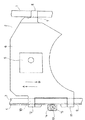
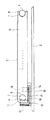
図1は本発明のピックアップ送り装置を示す要部の平面図、図2は本発明のピックアップ送り装置を示す要部の正面図である。
【0009】
図において、1は固定基板2に取付固定されている円柱状の第1ガイドシャフト、3は前記第1ガイドシャフト3に平行になるように前記固定基板2に取付固定されている円柱状の第2ガイドシャフトであり、前記第1ガイドシャフト1と対向する面の反対側の面にラック歯4が形成されている。
【0010】
5はディスクに記録されている信号の読み取り動作を行うピックアップ、6は前記ピックアップ5が搭載されているピックアップ支持部材であり、前記第1ガイドシャフト1と係合する溝7が形成されている第1支持アーム8、前記第2ガイドシャフト3が挿通する孔9及び10が形成されている第2支持アーム11及び第3支持アーム12が形成されている。
【0011】
13は前記第2ガイドシャフト3に形成されているラック歯4と噛み合った状態にある駆動歯車であり、前記ピックアップ支持部材6の下面に固定されている支持基板14に軸15によって回転可能に取付られている。16は前記支持基板14上に軸17によって回転可能に取付られている伝達歯車であり、前記駆動歯車13と噛み合った状態にある。
【0012】
18は前記ピックアップ支持部材6上に搭載されているとともにピックアップ5の移動動作時回転駆動されるピックアップ送り用モーター、19は前記ピックアップ送り用モーター18の回転軸に取付固定されているモーター用歯車であり、前記伝達歯車16と常時噛み合った状態にある。
【0013】
斯かる構成において、ピックアップ支持部材6に形成されている第2支持アーム11及び第3支持アーム12と第2ガイドシャフト3との係合動作は、ラック歯4が形成されている部分を除く円形状部にて行われるように設定されている。
【0014】
以上に説明したように本発明のピックアップ送り装置は構成されており、斯かる構成において、ピックアップ送り用モーター18が回転すると、その回転力がモーター用歯車19及び伝達歯車16を介して駆動歯車13に伝達される。前記駆動歯車13が回転すると、該駆動歯車13は第2ガイドシャフト3に形成されているラック歯4に噛み合った状態にあるため、ピックアップ支持部材6は第2ガイドシャフト3の軸方向、即ち矢印AまたはB方向への変位力を受けることになる。その結果、前記ピックアップ支持部材6は、第1ガイドシャフト1及び第2ガイドシャフト3によって案内且つ支持されながら矢印AまたはB方向へ移動せしめられる。従って、矢印A及びB方向をディスクの径方向に設定することによってピックアップ5をディスクの径方向に移動させることが出来、ディスクからの信号の読み取り動作を行うことが出来る。
【0016】
【発明の効果】
本発明のピックアップ送り装置は、ピックアップが搭載されているピックアップ支持部材をディスクの径方向へ案内するガイドシャフトにラック歯を形成するとともに該ラック歯に噛み合う駆動歯車を回転駆動するピックアップ送り用モーターを該ピックアップ支持部材上に搭載させるようにしたので、ガイドシャフトの長さを長くすることによって1つのピックアップを兼用して第1及び第2のディスク駆動部により回転駆動される各々のディスクに記録されている信号の読み取り動作等を行うように簡単に構成することが出来る。また、本発明は、第2ガイドシャフトのラック歯が形成される面を第1ガイドシャフトと対向する面の反対側にしたので、ラック歯に噛み合う駆動歯車の位置が第2ガイドシャフトの外側に配置されるので、ピックアップ送り装置の組立を容易に行うことが出来る。また、本発明は、ピックアップ支持部材を支持するべく設けられている第2支持アーム及び第3支持アームと第2ガイドシャフトとの係合動作をラック歯が形成されている部分を除く円形状部にて行うようにしたので、ピックアップ支持部材の変位動作をラック歯による影響を受けることなく円滑に行うことが出来、その結果ピックアップのディスクからの信号の読み取り特性を向上させることが出来るという利点を有している。
【図面の簡単な説明】
【図1】本発明のピックアップ送り装置を示す要部の平面図である。
【図2】本発明のピックアップ送り装置を示す要部の正面図である。
【符号の説明】
1 第1ガイドシャフト
2 固定基板
3 第2ガイドシャフト
4 ラック歯
5 ピックアップ
6 ピックアップ支持部材
13 駆動歯車
14 支持基板
16 伝達歯車
18 ピックアップ送り用モーター
19 モーター用歯車[0001]
BACKGROUND OF THE INVENTION
The present invention relates to a pickup feeding device that reads a signal recorded on a disk.
[0002]
[Prior art]
A disk player that performs an operation of reading a signal recorded on a disk by using an optical pickup is widely used. Such a pickup is configured to be moved by a pickup feeding motor in the radial direction of the disk. .
[0003]
Japanese Laid-Open Utility Model Publication No. 2-72470 discloses a technique for moving such a pickup by rotating a shaft provided with a feed groove on the outer periphery.
[0004]
[Problems to be solved by the invention]
As a typical disc player, a CD player is well known, but recently, a CD-ROM player used in combination with a personal computer has become widespread. Such a CD-ROM player, unlike a CD player that reproduces an audio signal, requires a high-speed signal reading operation, so that it is required to move the pickup at a high speed.
[0005]
The technique disclosed in the above-mentioned publication has a problem that it is difficult to move the pickup at a high speed because it is difficult to rotate the shaft having the feed groove on the outer periphery at a high speed. As a technique for solving such a problem, for example, as disclosed in Japanese Patent Laid-Open No. 9-198811, rack teeth are formed on a support that supports the pickup, and the pickup is driven by the rotational force of a gear meshing with the rack teeth. There is something to move. According to such a technique, although the pickup can be moved at a high speed, the movement distance of the pickup is determined by the length of the rack tooth. Therefore, in order to increase the movement distance, it is necessary to lengthen the rack tooth. As a result, there is a problem that the support for the pickup becomes heavy and the motor for carrying out the movement operation of the pickup becomes large and the current consumption increases.
[0006]
The present invention seeks to provide a pickup feeding apparatus that solves such problems.
[0007]
[Means for Solving the Problems]
The pickup feeding device according to the present invention is mounted on and fixed to the fixed substrate so as to be parallel to the first guide shaft, and is opposed to the first guide shaft. A second guide shaft having rack teeth formed on the surface or the opposite surface, and the first and second guide shafts are supported by the first and second guide shafts so as to be capable of displacement in the radial direction of the disk, and signals recorded on the disk A pickup support member on which a pickup for performing a reading operation is mounted, a pickup feed motor that is mounted on the pickup support member and is driven to rotate when the pickup is moved, and is rotatably mounted on the pickup support member And is rotationally driven by the pickup feeding motor, and It is more configuration and the drive gear in a state engaged with the rack teeth formed on the serial second guide shaft.
[0008]
【Example】
FIG. 1 is a plan view of a main part showing a pickup feeding apparatus of the present invention, and FIG. 2 is a front view of the main part showing a pickup feeding apparatus of the present invention.
[0009]
In the figure, reference numeral 1 denotes a cylindrical first guide shaft attached and fixed to the fixed substrate 2, and 3 denotes a cylindrical first guide shaft attached and fixed to the fixed substrate 2 so as to be parallel to the first guide shaft 3. A rack tooth 4 is formed on the surface opposite to the surface facing the first guide shaft 1.
[0010]
[0011]
A
[0012]
[0013]
In such a configuration, the engagement operation of the
[0014]
As described above, the pickup feeding device of the present invention is configured. In such a configuration, when the
[0016]
【The invention's effect】
A pickup feeding device according to the present invention includes a pickup feeding motor that forms rack teeth on a guide shaft that guides a pickup supporting member on which a pickup is mounted in a radial direction of a disk and that rotationally drives a drive gear that meshes with the rack teeth. Since it is mounted on the pickup support member, the length of the guide shaft is increased, so that it is recorded on each of the disks that are rotated by the first and second disk drive units as one pickup. It can be easily configured to perform a signal reading operation or the like. In the present invention, the surface of the second guide shaft on which the rack teeth are formed is on the opposite side of the surface facing the first guide shaft, so that the position of the drive gear meshing with the rack teeth is outside the second guide shaft. As a result, the pickup feeding device can be easily assembled. In addition, the present invention provides a second support arm provided to support the pickup support member, and a circular portion excluding a portion where rack teeth are formed in the engagement operation between the third support arm and the second guide shaft. Therefore, it is possible to smoothly perform the displacement operation of the pickup support member without being affected by the rack teeth, and as a result, it is possible to improve the signal reading characteristics from the disk of the pickup. Have.
[Brief description of the drawings]
FIG. 1 is a plan view of a main part showing a pickup feeding device of the present invention.
FIG. 2 is a front view of a main part showing a pickup feeding device of the present invention.
[Explanation of symbols]
DESCRIPTION OF SYMBOLS 1 1st guide shaft 2 Fixed substrate 3 2nd guide shaft 4
Claims (1)
Priority Applications (1)
| Application Number | Priority Date | Filing Date | Title |
|---|---|---|---|
| JP03613998A JP3691237B2 (en) | 1998-02-18 | 1998-02-18 | Pickup feeder |
Applications Claiming Priority (1)
| Application Number | Priority Date | Filing Date | Title |
|---|---|---|---|
| JP03613998A JP3691237B2 (en) | 1998-02-18 | 1998-02-18 | Pickup feeder |
Publications (2)
| Publication Number | Publication Date |
|---|---|
| JPH11232807A JPH11232807A (en) | 1999-08-27 |
| JP3691237B2 true JP3691237B2 (en) | 2005-09-07 |
Family
ID=12461465
Family Applications (1)
| Application Number | Title | Priority Date | Filing Date |
|---|---|---|---|
| JP03613998A Expired - Fee Related JP3691237B2 (en) | 1998-02-18 | 1998-02-18 | Pickup feeder |
Country Status (1)
| Country | Link |
|---|---|
| JP (1) | JP3691237B2 (en) |
-
1998
- 1998-02-18 JP JP03613998A patent/JP3691237B2/en not_active Expired - Fee Related
Also Published As
| Publication number | Publication date |
|---|---|
| JPH11232807A (en) | 1999-08-27 |
Similar Documents
| Publication | Publication Date | Title |
|---|---|---|
| JPH05205376A (en) | Disk clamping device | |
| JP3686539B2 (en) | Pickup feed mechanism | |
| JP3691237B2 (en) | Pickup feeder | |
| JP2718182B2 (en) | Disc player | |
| JP3037117B2 (en) | Pickup feeder | |
| JP2002334450A (en) | Pickup transfer device of optical disk unit | |
| JPH09297974A (en) | Pickup feeding device | |
| JPH0255871B2 (en) | ||
| JP3568416B2 (en) | Guide shaft fixing device for optical pickup | |
| KR100249549B1 (en) | A roulette turning device of cd changer | |
| JPH08212727A (en) | Pickup feeding device | |
| KR100249550B1 (en) | A roulette turning device of cd changer | |
| JP3639458B2 (en) | Guide shaft fixing device | |
| JPH063659B2 (en) | Magnetic recording / reproducing device | |
| JP3091591B2 (en) | Pickup feeder | |
| JP2004348782A (en) | Disk loading device | |
| KR940006127B1 (en) | Double side player for multi-disk | |
| JP2590777Y2 (en) | Pickup transfer structure of disc player | |
| JPS61227280A (en) | Disk player | |
| JP3219603B2 (en) | Pickup feeder | |
| JP3316395B2 (en) | Pickup feeder | |
| KR20040090823A (en) | Optical pick up apparatus for optical disc drive | |
| JP2001229631A (en) | Pickup feeder | |
| JP2600034Y2 (en) | Loading mechanism of optical disk player | |
| CN1277436A (en) | High-speed optical disc reading device and method thereof |
Legal Events
| Date | Code | Title | Description |
|---|---|---|---|
| A977 | Report on retrieval |
Free format text: JAPANESE INTERMEDIATE CODE: A971007 Effective date: 20040921 |
|
| A131 | Notification of reasons for refusal |
Free format text: JAPANESE INTERMEDIATE CODE: A131 Effective date: 20040928 |
|
| A521 | Written amendment |
Free format text: JAPANESE INTERMEDIATE CODE: A523 Effective date: 20041104 |
|
| TRDD | Decision of grant or rejection written | ||
| A01 | Written decision to grant a patent or to grant a registration (utility model) |
Free format text: JAPANESE INTERMEDIATE CODE: A01 Effective date: 20050531 |
|
| A61 | First payment of annual fees (during grant procedure) |
Free format text: JAPANESE INTERMEDIATE CODE: A61 Effective date: 20050615 |
|
| LAPS | Cancellation because of no payment of annual fees |