JP3689712B2 - Luggage platform - Google Patents
Luggage platform Download PDFInfo
- Publication number
- JP3689712B2 JP3689712B2 JP2003398559A JP2003398559A JP3689712B2 JP 3689712 B2 JP3689712 B2 JP 3689712B2 JP 2003398559 A JP2003398559 A JP 2003398559A JP 2003398559 A JP2003398559 A JP 2003398559A JP 3689712 B2 JP3689712 B2 JP 3689712B2
- Authority
- JP
- Japan
- Prior art keywords
- leg
- hole
- key member
- engaging
- table body
- Prior art date
- Legal status (The legal status is an assumption and is not a legal conclusion. Google has not performed a legal analysis and makes no representation as to the accuracy of the status listed.)
- Expired - Lifetime
Links
- 230000002787 reinforcement Effects 0.000 description 2
- 230000003014 reinforcing effect Effects 0.000 description 2
- 238000000638 solvent extraction Methods 0.000 description 2
- 238000000034 method Methods 0.000 description 1
- 238000005192 partition Methods 0.000 description 1
- 125000006850 spacer group Chemical group 0.000 description 1
- 239000002023 wood Substances 0.000 description 1
Images


Classifications
-
- B—PERFORMING OPERATIONS; TRANSPORTING
- B65—CONVEYING; PACKING; STORING; HANDLING THIN OR FILAMENTARY MATERIAL
- B65D—CONTAINERS FOR STORAGE OR TRANSPORT OF ARTICLES OR MATERIALS, e.g. BAGS, BARRELS, BOTTLES, BOXES, CANS, CARTONS, CRATES, DRUMS, JARS, TANKS, HOPPERS, FORWARDING CONTAINERS; ACCESSORIES, CLOSURES, OR FITTINGS THEREFOR; PACKAGING ELEMENTS; PACKAGES
- B65D90/00—Component parts, details or accessories for large containers
- B65D90/12—Supports
- B65D90/14—Legs, e.g. detachable
-
- B—PERFORMING OPERATIONS; TRANSPORTING
- B65—CONVEYING; PACKING; STORING; HANDLING THIN OR FILAMENTARY MATERIAL
- B65D—CONTAINERS FOR STORAGE OR TRANSPORT OF ARTICLES OR MATERIALS, e.g. BAGS, BARRELS, BOTTLES, BOXES, CANS, CARTONS, CRATES, DRUMS, JARS, TANKS, HOPPERS, FORWARDING CONTAINERS; ACCESSORIES, CLOSURES, OR FITTINGS THEREFOR; PACKAGING ELEMENTS; PACKAGES
- B65D88/00—Large containers
- B65D88/02—Large containers rigid
- B65D88/12—Large containers rigid specially adapted for transport
- B65D88/129—Transporter frames for containers
Landscapes
- Engineering & Computer Science (AREA)
- Mechanical Engineering (AREA)
- Pallets (AREA)
Description
本発明は、トラックの箱形荷台またはコンテナ等を上下に仕切って荷台空間を有効に活用する荷物載せ台に関する。 The present invention relates to a luggage platform that efficiently utilizes a cargo space by partitioning a box-shaped cargo bed or a container of a truck up and down.
従来、荷物を多段に積載させる技術がある。(例えば特許文献1参照) Conventionally, there is a technique for loading packages in multiple stages. (For example, see Patent Document 1)
前記従来技術は、上下多段に荷物を載せることができるが、トラックの荷台に支柱(脚)を固定させ、上下段アーム(テーブル本体)を昇降シリンダによって上下に移動させるから、前記の支柱及びアームの折畳または分解などを容易に行い得ず、例えば往路で軽量貨物を二段積み運搬しかつ復路で重量物を一段積み運搬する作業などを容易に行い得ない等の問題がある。 In the above prior art, a load can be loaded in multiple stages, but the column (leg) is fixed to the truck bed and the upper and lower arms (table body) are moved up and down by the lifting cylinder. Cannot be easily folded or disassembled. For example, it is not possible to easily carry a two-stage stack of light-weight cargoes on the forward path and a single-stage stack of heavy objects on the return path.
そこで本発明は、請求項1の如く、トラックの箱形荷台を上下に仕切るテーブル本体に、トラックの箱形荷台の約半分の高さの脚を折畳み自在に設ける荷物載せ台において、矩形のテーブル本体の対向する側部に脚ホルダを固定させ、互に連通させる遊嵌孔と係合孔を脚ホルダに設け、遊嵌孔または係合孔に移動可能なキー部材を脚の上部に設けると共に、遊嵌孔にキー部材を内挿時に脚を折畳み方向に移動させる脚引張り部材を脚下端部に連結させたものである。 Accordingly, the present invention provides a rectangular table in which a table body for vertically partitioning a truck box-shaped cargo bed is provided with a leg that is approximately half the height of the truck box-shaped cargo bed in a foldable manner. The leg holder is fixed to the opposite side portions of the main body, and a loose fitting hole and an engaging hole that communicate with each other are provided in the leg holder, and a key member that can move to the loose fitting hole or the engaging hole is provided on the upper portion of the leg. A leg pulling member that moves the leg in the folding direction when the key member is inserted into the loose fitting hole is connected to the lower end of the leg.
また、請求項2の如く、係合孔にキー部材を係入固定させる脚起立保持用のワンタッチ式ロック部材をテーブル本体と脚間に介設させたものである。 According to a second aspect of the present invention, a one-touch type locking member for holding the leg upright for engaging and fixing the key member in the engaging hole is interposed between the table main body and the leg.
然るに、本発明は、トラックの箱形荷台を上下に仕切るテーブル本体に、トラックの箱形荷台の約半分の高さの脚を折畳み自在に設ける荷物載せ台において、矩形のテーブル本体の対向する側部に脚ホルダを固定させ、互に連通させる遊嵌孔と係合孔を脚ホルダに設け、遊嵌孔または係合孔に移動可能なキー部材を脚の上部に設けると共に、遊嵌孔にキー部材を内挿時に脚を折畳み方向に移動させる脚引張り部材を脚下端部に連結させたもので、脚の横倒しによってテーブル本体を低くし得、貨物に合わせてテーブル本体を高くしたり低くして各種の貨物を効率良く運搬し得ると共に、脚の横倒しを地上より容易に可能とさせるものである。 However, the present invention provides a load platform in which legs approximately half the height of a truck box-type cargo bed are foldable on a table body that divides the box-type cargo bed of a truck up and down. The leg holder is fixed to the portion, and a loose fitting hole and an engaging hole that communicate with each other are provided in the leg holder. A loosely fitting hole or a key member that can be moved to the engaging hole is provided on the top of the leg, and the loosely fitting hole A leg tension member that moves the leg in the folding direction when the key member is inserted is connected to the lower end of the leg, and the table body can be lowered by lying down on the leg, and the table body can be raised or lowered according to the cargo. In addition to efficiently transporting various cargoes, the legs can be easily laid down from the ground.
また、請求項2の如く、係合孔にキー部材を係入固定させる脚起立保持用のワンタッチ式ロック部材をテーブル本体と脚間に介設させたもので、フォークリフトカーのフォークを用いてテーブル本体を持上げたり降ろして、脚を起立させたり倒状させる作業を容易に行い得ると共に、脚の起立時には正確な起立姿勢を安定保持させるものである。 According to a second aspect of the present invention, there is provided a one-touch type locking member for holding the leg upright for engaging and fixing the key member in the engagement hole between the table main body and the leg, and the table using the fork of the forklift car. The main body can be lifted or lowered to easily erect or incline the leg, and an accurate standing posture can be stably maintained when the leg erects.
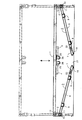
以下、本発明の実施例を図面に基づいて詳述する。図1は全体の正面図であり、四角パイプで形成する格子形のテーブル本体1と、平面視矩形のテーブル本体1の対向する側部下面に固定させる脚ホルダ2と、脚ホルダ2に折畳み自在に設ける脚3とを備えるもので、図2、図3のように、フォークリフトカーのフォーク4によってテーブル本体1を支えて脚3を起立または倒状させ、図3の状態でテーブル本体1と脚3の間に木材製のスペーサ5を挾んでフォーク4を出入させる空間6を形成する。
Embodiments of the present invention will be described below in detail with reference to the drawings. FIG. 1 is a front view of the whole, a lattice-shaped table
さらに、図4、図5に示す如く、横フレーム7と二組4本の縦フレーム8と上下2本の補強フレーム9によって脚3を構成し、端面が楕円形の平板形のキー部材10を縦フレーム8の上端に固定させ、キー部材10の長手方向と略同一直径の円形の遊嵌孔11と、キー部材10の端面と略同一大きさの長孔形の係合孔12とを脚ホルダ2に開設させ、遊嵌孔11上部と係合孔12下部を連通させて各孔11・12間で移動自在にキー部材10を内挿させ、係合孔12にキー部材10を係入させて縦フレーム8を起立姿勢でホルダ2に固定させ、テーブル本体1を縦フレーム8によって所定高さに支える一方、フォーク4によってテーブル本体1を持ち上げることにより、キー部材10が遊嵌孔11に移動し、キー部材10を支点に縦フレーム8が回転して倒状する。なお、図3のように、縦フレーム8が倒状しているとき、フォーク4によってテーブル本体1を持上げることによって縦フレーム8が垂直方向に回転し、次いでテーブル本体1の下降によって係合孔12にキー部材10が係入する。
Further, as shown in FIGS. 4 and 5, a
また、図6・図7のように、脚3の横フレーム7側面に軸16の両端部を固定させ、横フレーム7側面の切欠17を介して軸16の中間に丸パイプローラ形の輪体18を回転自在に軸支させ、図2、図3のように、脚3が倒状姿勢のときに輪体18を床面上に転動させ、脚3の起状動作をスムーズに行わせる。なお、複数のテーブル本体1を並設させるとき、隣り合う脚3の補強フレーム9をボルト孔19を介してボルト止め固定させ、脚3を連結させて複数のテーブル本体を連設させる。
Further, as shown in FIGS. 6 and 7, both ends of the
さらに、図4のように、テーブル本体1と上補強フレーム9との間に脚起立保持用のワンタッチ式ロック部材13を設けるもので、上補強フレーム9の上部取付台14にロック部材13の1つであるパッチン錠13aを取付けると共に、パッチン錠13aの係止輪体13bを係合させるフック15をテーブル本体1下面に固設させて、キー部材10を係合孔12に係入させた状態でフック15にパッチン錠13aを係合させるとき、脚3を垂直姿勢で起立保持させる。
Further, as shown in FIG. 4, a one-touch
そして、左右縦フレーム8の下端部でトラック20の箱形荷台21の荷物積み降ろし側に係止金具22を固定させ、紐或いはワイヤなどの引張り部材23先端に固定させる抜止付フック24を係止金具22に係合させ、図1のようにテーブル本体1の下面略中央に回転板25を介し方向自在に配設させる滑車26に引張り部材23中間を巻回させ、引張り部材23の他端の引張り操作部材23aを荷台21側方まで臨ませて、脚3の起立状態でフォーク4によりテーブル本体1を若干持上げてキー部材10を遊嵌孔11に移動させるとき、引張り部材23を引張って脚3を内方向に傾け、以後はテーブル本体1の自重により脚3を折畳みさせるように構成している。
The
なお、上述実施例ではテーブル本体1に滑車26を設ける構成を示したが、図9のように左右縦フレーム8の係止金具22間を1本或いは2本の引張り部材23で直接的に連結させ、引張り部材23中央に連結させる1本の紐など引張り操作部材23の引張りでもって脚3を傾けるようにしても良い。
In the above-described embodiment, the
なおこのような引張り部材23は必要時のみに取付け、運搬時や貨物27・28積み降ろし時には適宜取外すものである。
Such a
本実施例は上記の如く構成するものにして、図8のように、脚3を起立させてテーブル本体1を高位置に設け、荷台21をテーブル本体1によって上下に仕切り、荷台21床面とテーブル本体1上面との2段に軽い貨物22を積み、荷台21を有効に利用すると共に、脚3を倒してテーブル本体1を荷台21床面の低い位置に設け、重い貨物28または高い貨物をテーブル本体1上面に積むもので、貨物27・28を荷台21側面からフォークリフトカーによって出入させると共に、同じフォークリフトカーを用いてテーブル本体1の上げ降しを行う。
This embodiment is configured as described above, and as shown in FIG. 8, the
上記からも明らかなように、トラック20の箱形荷台21を上下に仕切るテーブル本体1に、トラック20の箱形荷台21の約半分の高さの脚3を折畳み自在に設ける荷物載せ台において、矩形のテーブル本体1の対向する側部に脚ホルダ2を固定させ、互に連通させる遊嵌孔11と係合孔12を脚ホルダ2に設け、遊嵌孔11または係合孔12に移動可能なキー部材10を脚3の上部に設けると共に、遊嵌孔11にキー部材10を内挿時に脚3を折畳み方向に移動させる脚引張り部材23を脚3下端部に連結させたもので、脚3の横倒しによってテーブル本体1を低くすることができ、貨物27・28に合わせてテーブル本体1を高くしたり低くして各種の貨物27・28を効率良く運搬することができると共に、脚3の横倒しを地上より容易に可能とさせることができて、テーブル本体1を高低させる作業の作業性を向上させることができる。
As is clear from the above, in the luggage platform in which the
また、係合孔12にキー部材10を係入固定させる脚起立保持用のワンタッチ式ロック部材13をテーブル本体1と脚3間に介設させたもので、フォークリフトカーのフォーク4を用いてテーブル本体1を持上げたり降ろして、脚3を起立させたり倒状させる作業を容易に行うことができると共に、脚3の起立時には正確な起立姿勢を安定保持させることができる。
Further, a one-touch
1 テーブル本体
2 脚ホルダ
3 脚
10 キー部材
11 遊嵌孔
12 係合孔
13 ロック部材(パッチン錠)
20 トラック
21 荷台
23 引張り部材(紐)
DESCRIPTION OF
20
Claims (2)
Priority Applications (1)
| Application Number | Priority Date | Filing Date | Title |
|---|---|---|---|
| JP2003398559A JP3689712B2 (en) | 2003-11-28 | 2003-11-28 | Luggage platform |
Applications Claiming Priority (1)
| Application Number | Priority Date | Filing Date | Title |
|---|---|---|---|
| JP2003398559A JP3689712B2 (en) | 2003-11-28 | 2003-11-28 | Luggage platform |
Publications (2)
| Publication Number | Publication Date |
|---|---|
| JP2005153815A JP2005153815A (en) | 2005-06-16 |
| JP3689712B2 true JP3689712B2 (en) | 2005-08-31 |
Family
ID=34723373
Family Applications (1)
| Application Number | Title | Priority Date | Filing Date |
|---|---|---|---|
| JP2003398559A Expired - Lifetime JP3689712B2 (en) | 2003-11-28 | 2003-11-28 | Luggage platform |
Country Status (1)
| Country | Link |
|---|---|
| JP (1) | JP3689712B2 (en) |
Families Citing this family (1)
| Publication number | Priority date | Publication date | Assignee | Title |
|---|---|---|---|---|
| JP2008068690A (en) * | 2006-09-13 | 2008-03-27 | Teruo Kashiwabara | Cargo placement base |
-
2003
- 2003-11-28 JP JP2003398559A patent/JP3689712B2/en not_active Expired - Lifetime
Also Published As
| Publication number | Publication date |
|---|---|
| JP2005153815A (en) | 2005-06-16 |
Similar Documents
| Publication | Publication Date | Title |
|---|---|---|
| US6513442B1 (en) | Foldable container for vehicles | |
| JP5390966B2 (en) | Cargo rack | |
| JP6933892B2 (en) | palette | |
| JP2009120202A (en) | Upper stage rack for freight, and lower stage rack for freight | |
| ZA200603713B (en) | Rack for freight | |
| US20070031231A1 (en) | Gas cylinder lift | |
| KR101165568B1 (en) | Container type foldable pallet | |
| JP3689712B2 (en) | Luggage platform | |
| JP2003312655A (en) | Folding housing box | |
| JP2008068690A (en) | Cargo placement base | |
| KR102079642B1 (en) | Stacking rack | |
| JP2017081301A (en) | Roll box pallet | |
| JP5596988B2 (en) | Cargo carrier rack | |
| JP2007186220A (en) | Returnable case for container | |
| JP2013121881A (en) | Jig for transporting passenger conveyor and method for transporting passenger conveyor | |
| JP3485395B2 (en) | Storage container for foldable returnable container | |
| JPH10310208A (en) | Method and device for loading into tire warehouse, and storage rack | |
| JP5188919B2 (en) | Foldable container | |
| JP4487187B2 (en) | rack | |
| JP4898189B2 (en) | Luggage platform | |
| JP3180951U (en) | rack | |
| JP3173308U (en) | Movable rack device for loading wire coils, etc., and truck or trailer | |
| CN216443523U (en) | Article loading and unloading vehicle device | |
| JP4805405B1 (en) | Folding cargo rack | |
| JP2005041299A (en) | Load placing table |
Legal Events
| Date | Code | Title | Description |
|---|---|---|---|
| TRDD | Decision of grant or rejection written | ||
| R150 | Certificate of patent or registration of utility model |
Free format text: JAPANESE INTERMEDIATE CODE: R150 Ref document number: 3689712 Country of ref document: JP Free format text: JAPANESE INTERMEDIATE CODE: R150 |
|
| S111 | Request for change of ownership or part of ownership |
Free format text: JAPANESE INTERMEDIATE CODE: R313113 |
|
| R350 | Written notification of registration of transfer |
Free format text: JAPANESE INTERMEDIATE CODE: R350 |
|
| FPAY | Renewal fee payment (event date is renewal date of database) |
Free format text: PAYMENT UNTIL: 20090624 Year of fee payment: 4 |
|
| R250 | Receipt of annual fees |
Free format text: JAPANESE INTERMEDIATE CODE: R250 |
|
| FPAY | Renewal fee payment (event date is renewal date of database) |
Free format text: PAYMENT UNTIL: 20100624 Year of fee payment: 5 |
|
| R250 | Receipt of annual fees |
Free format text: JAPANESE INTERMEDIATE CODE: R250 |
|
| FPAY | Renewal fee payment (event date is renewal date of database) |
Free format text: PAYMENT UNTIL: 20100624 Year of fee payment: 5 |
|
| FPAY | Renewal fee payment (event date is renewal date of database) |
Free format text: PAYMENT UNTIL: 20110624 Year of fee payment: 6 |
|
| R250 | Receipt of annual fees |
Free format text: JAPANESE INTERMEDIATE CODE: R250 |
|
| FPAY | Renewal fee payment (event date is renewal date of database) |
Free format text: PAYMENT UNTIL: 20120624 Year of fee payment: 7 |
|
| R250 | Receipt of annual fees |
Free format text: JAPANESE INTERMEDIATE CODE: R250 |
|
| FPAY | Renewal fee payment (event date is renewal date of database) |
Free format text: PAYMENT UNTIL: 20120624 Year of fee payment: 7 |
|
| FPAY | Renewal fee payment (event date is renewal date of database) |
Free format text: PAYMENT UNTIL: 20130624 Year of fee payment: 8 |
|
| R250 | Receipt of annual fees |
Free format text: JAPANESE INTERMEDIATE CODE: R250 |
|
| FPAY | Renewal fee payment (event date is renewal date of database) |
Free format text: PAYMENT UNTIL: 20140624 Year of fee payment: 9 |
|
| R250 | Receipt of annual fees |
Free format text: JAPANESE INTERMEDIATE CODE: R250 |
|
| R250 | Receipt of annual fees |
Free format text: JAPANESE INTERMEDIATE CODE: R250 |
|
| R250 | Receipt of annual fees |
Free format text: JAPANESE INTERMEDIATE CODE: R250 |
|
| R250 | Receipt of annual fees |
Free format text: JAPANESE INTERMEDIATE CODE: R250 |
|
| R250 | Receipt of annual fees |
Free format text: JAPANESE INTERMEDIATE CODE: R250 |
|
| R250 | Receipt of annual fees |
Free format text: JAPANESE INTERMEDIATE CODE: R250 |
|
| R250 | Receipt of annual fees |
Free format text: JAPANESE INTERMEDIATE CODE: R250 |
|
| R250 | Receipt of annual fees |
Free format text: JAPANESE INTERMEDIATE CODE: R250 |
|
| EXPY | Cancellation because of completion of term |