JP3689340B2 - Varifocal lens barrel - Google Patents
Varifocal lens barrel Download PDFInfo
- Publication number
- JP3689340B2 JP3689340B2 JP2001033302A JP2001033302A JP3689340B2 JP 3689340 B2 JP3689340 B2 JP 3689340B2 JP 2001033302 A JP2001033302 A JP 2001033302A JP 2001033302 A JP2001033302 A JP 2001033302A JP 3689340 B2 JP3689340 B2 JP 3689340B2
- Authority
- JP
- Japan
- Prior art keywords
- focus
- ring
- cam
- lens barrel
- frame
- Prior art date
- Legal status (The legal status is an assumption and is not a legal conclusion. Google has not performed a legal analysis and makes no representation as to the accuracy of the status listed.)
- Expired - Fee Related
Links
- 230000003287 optical effect Effects 0.000 claims description 96
- 230000002093 peripheral effect Effects 0.000 claims description 25
- 230000005540 biological transmission Effects 0.000 claims description 15
- 239000007769 metal material Substances 0.000 claims description 10
- 229920003002 synthetic resin Polymers 0.000 claims description 9
- 239000000057 synthetic resin Substances 0.000 claims description 9
- 239000000463 material Substances 0.000 claims description 5
- 238000000034 method Methods 0.000 description 5
- 230000012447 hatching Effects 0.000 description 3
- 238000003780 insertion Methods 0.000 description 3
- 230000037431 insertion Effects 0.000 description 3
- 230000011514 reflex Effects 0.000 description 3
- 238000010586 diagram Methods 0.000 description 2
- 238000006073 displacement reaction Methods 0.000 description 2
- 238000003384 imaging method Methods 0.000 description 2
- 238000004519 manufacturing process Methods 0.000 description 2
- 238000000465 moulding Methods 0.000 description 2
- DUGOZIWVEXMGBE-UHFFFAOYSA-N Methylphenidate Chemical compound C=1C=CC=CC=1C(C(=O)OC)C1CCCCN1 DUGOZIWVEXMGBE-UHFFFAOYSA-N 0.000 description 1
- 238000013459 approach Methods 0.000 description 1
- 238000005452 bending Methods 0.000 description 1
- 230000006835 compression Effects 0.000 description 1
- 238000007906 compression Methods 0.000 description 1
- 239000000470 constituent Substances 0.000 description 1
- 230000000694 effects Effects 0.000 description 1
- 229940053650 focalin Drugs 0.000 description 1
- 230000001771 impaired effect Effects 0.000 description 1
- 239000002184 metal Substances 0.000 description 1
- 238000003825 pressing Methods 0.000 description 1
- 239000004576 sand Substances 0.000 description 1
- 238000003860 storage Methods 0.000 description 1
Images


Classifications
-
- G—PHYSICS
- G02—OPTICS
- G02B—OPTICAL ELEMENTS, SYSTEMS OR APPARATUS
- G02B7/00—Mountings, adjusting means, or light-tight connections, for optical elements
- G02B7/02—Mountings, adjusting means, or light-tight connections, for optical elements for lenses
- G02B7/04—Mountings, adjusting means, or light-tight connections, for optical elements for lenses with mechanism for focusing or varying magnification
- G02B7/10—Mountings, adjusting means, or light-tight connections, for optical elements for lenses with mechanism for focusing or varying magnification by relative axial movement of several lenses, e.g. of varifocal objective lens
Landscapes
- Physics & Mathematics (AREA)
- General Physics & Mathematics (AREA)
- Optics & Photonics (AREA)
- Lens Barrels (AREA)
Description
【0001】
【技術分野】
本発明は、バリフォーカルレンズ鏡筒に関する。
【0002】
【従来技術及びその問題点】
光学機器においてフォーカシング等の目的でレンズ(群)を光軸方向に移動させるために、相対回転可能な一対の環状部材の一方にカムまたはリードを設け、他方にカムフォロアまたはリードフォロアを設けた構造が知られている。これらのカムやリードとフォロアの嵌合関係によって、一対の環状部材は、相対回転したときに光軸方向にも相対移動する。カムやリードとフォロアの構造としては、溝と突起が嵌合するものや突起同士が嵌合するものが知られているが、この嵌合部分にガタがあるとレンズの倒れや光軸方向の位置ずれの原因となるため、ガタをできるだけなくし像性能を安定させることが望まれている。また、レンズを正しく移動させるため、カムやリードはできるだけ滑らかに摺動することが好ましい。
【0003】
また、焦点距離を変更すると焦点面が移動するレンズとして定義されるバリフォーカルレンズが知られている。バリフォーカルレンズでは、焦点距離を変えると、同一距離の被写体に合焦させるためのフォーカスレンズ群の繰出位置が変化する。オートフォーカスカメラでは、焦点距離が変化するときの焦点面の移動を考慮して(補償するように)フォーカスレンズ群の繰出位置(待機位置からの移動量)を定めればよく、また、マニュアルフォーカスの一眼レフカメラでも、焦点距離を変更したときの焦点面の移動(ぼけ)をファインダ視でき、ぼけがなくなるように距離環(フォーカス環)を回転させればよいから、フォーカシングについての実用上の問題はない。
【0004】
しかし、一眼レフカメラ用では、距離環に撮影距離目盛を刻む(表示する)必要があり、どの焦点距離においても、その撮影距離目盛が示した距離にある被写体に合焦させなければならない。別言すると、同じ距離の被写体に合焦させるとき、異なる焦点距離に応じ、例えば無限遠撮影位置からの距離環の同じ回転角で異なる距離だけフォーカスレンズ群を移動させて被写体に合焦させなければならない。すなわち、操作上は、恰も、焦点距離を変えても焦点面が移動しないズームレンズと同じ操作性が要求される。この意味で、バリフォーカルレンズ鏡筒と、ズームレンズ鏡筒とに実用上の差はない。このようなバリフォーカルレンズ鏡筒は、一般的に構造が複雑であるばかりか、距離環の単位回転角当たりのフォーカスレンズ群の繰出位置を焦点距離変化に応じて変化させるフォーカスカムと、ズーミングを行うためのズームカムとの相互干渉(影響)を除くことが困難であるという問題があった。この課題を解決するため、本出願人は、フォーカスカムとズームカムとが干渉することなくズーミング可能なバリフォーカルレンズ鏡筒を提案した(特願2000-201928号、未公開)。この先行発明の概念は以下の本件実施形態の説明で述べるが、このようなバリフォーカルレンズ鏡筒では特に、フォーカスレンズ群の位置ずれや倒れによる像性能への影響が大きいので、フォーカスレンズ群の支持案内機構におけるガタをできるだけなくし像性能を安定させることが望ましい。また、フォーカスレンズ群を円滑に移動させることが望ましい。
【0005】
【発明の目的】
本発明は、バリフォーカルレンズ鏡筒におけるフォーカスレンズ群の倒れや光軸方向の位置ずれを防ぎ、かつ円滑にフォーカスレンズ群を案内して、安定した像性能を得ることを目的とする。
【0006】
【発明の概要】
本発明は、焦点距離を変化させる光軸方向に可動の複数の変倍レンズ群を有し、そのうちの一つのレンズ群は、変倍と焦点調節の両方の機能を持ち、異なる焦点距離において同じ被写体距離に対する合焦繰出位置が変化するフォーカスレンズ群であるバリフォーカルレンズ鏡筒において、回転操作されるフォーカス操作環;光軸を中心とする半径方向においてフォーカス操作環の内側に位置し、上記フォーカスレンズ群を支持するフォーカスレンズ枠;光軸を中心とする半径方向においてフォーカス操作環とフォーカスレンズ枠の間に位置し、フォーカスレンズ群以外の上記変倍レンズ群を駆動するレンズ駆動環;フォーカス操作環の内面側に固定される外径腕と、フォーカスレンズ枠に対して光軸方向に相対移動可能かつ光軸を中心とする相対回動は不能に係合する内径腕と、レンズ駆動環の光軸方向後端部の後方で内径腕と外径腕のそれぞれの光軸方向後端部を接続する半径方向部とを有し、フォーカス操作環の回転をフォーカスレンズ枠に伝達する、円周方向に一つ設けたフォーカスレバー;フォーカスレンズ枠の外側に位置するフォーカスガイド環:フォーカスレンズ枠の外面とフォーカスガイド環の内面の一方に設けた、焦点距離変化による像面移動を補償する非線形形状を有するフォーカスカム;フォーカスレンズ枠の外面とフォーカスガイド環の内面の他方に設けた、このフォーカスカムと係合し、フォーカス操作環により回転駆動されるフォーカスレンズ枠を該フォーカスカムの形状に従って光軸方向に移動させるフォロア;及び、焦点距離変化に応じてフォーカスカムとフォロアの係合位置を変化させ、フォーカス操作環の一定の回転角あたりのフォーカスレンズ群の移動量を焦点距離に応じて変化させるフォーカスカム使用域調整機構;を有し、フォーカスカムは有底のフォーカスカム溝からなっており、フォロアは、フォーカスレンズ枠またはフォーカスガイド環に形成した半径方向の球体移動溝に移動自在に嵌まり、さらにこの有底のフォーカスカム溝に嵌まる、球体からなるフォロアからなっており、この球体フォロアを有底のフォーカスカム溝と係合する方向へ付勢する付勢部材を備えたことを特徴とする。このフォーカスカム溝、球体フォロア及び付勢部材を有するガイド構造によれば、バリフォーカルレンズ鏡筒におけるフォーカスレンズ群を正しく円滑に移動させ、かつその倒れや位置ずれを防ぐことができる。
【0007】
このバリフォーカルレンズ鏡筒では、さらに、フォーカス操作環とは独立して回転操作されるズーム操作環;光軸方向に案内され、フォーカスガイド環を介してフォーカスレンズ枠を支持した中間移動枠;を備え、フォーカス操作環とフォーカスレンズ枠の間に位置するレンズ駆動環として、ズーム操作環の回転操作により、複数の変倍レンズ群と中間移動枠とを所定の軌跡で光軸方向に移動させるズーム繰出環を備え、上述のフォーカスカム使用域調整機構は、フォーカスガイド環を、ズーム繰出環と回転方向に一体に回動させ光軸方向には相対移動可能とさせる回転伝達部材;及び、中間移動枠とフォーカスガイド環の対向する周面の一方と他方に設けた、フォーカスカム溝と同形状の調整用カムと、この調整用カムと係合する調整用カムフォロア;を有するように構成することが好ましい。該構成では、同形状の調整用カムとフォーカスカム溝に対し、調整用カムフォロアと球体フォロアが同位置に位置するとき、フォーカスガイド環は、ズーム繰出環の回転に応じて該フォーカスカム溝と調整用カムとに案内され、フォーカスレンズ枠と中間移動枠の両方に対して同角度相対回転すると共に光軸方向に同量相対移動し、このフォーカスガイド環の動作により、フォーカスカム溝と球体フォロアの係合位置を変化させることができる。
【0008】
また本発明のバリフォーカルレンズ鏡筒では、さらに、固定環を備え、ズーム繰出環は、該固定環に、回転を与えられたとき光軸方向に移動する態様で支持され、中間移動枠は、このズーム繰出環に相対回転は自在にかつ光軸方向の相対移動は生じない態様で支持されていることが好ましい。
【0009】
例えば、フォーカスカム溝はフォーカスレンズ枠の外面に形成され、球体フォロアはフォーカスガイド環の内面に設けることができる。
【0012】
以上の本発明のバリフォーカルレンズ鏡筒では、フォーカスガイド溝、球体フォロア及び付勢部材はそれぞれ、円周方向に等間隔で3つ設けられていることが望ましい。
【0013】
また、本発明のバリフォーカルレンズ鏡筒のフォーカスカム溝は、その深さが浅くなるにつれて徐々に開口幅を広くする台形の断面形状溝、V字状の断面形状溝、部分円形状の断面形状溝の各態様とさせることができる。
【0014】
また、本発明のバリフォーカルレンズ鏡筒における付勢部材は、コイルばね、片持ち状の板ばね、両持ち状の板ばね等とすることができる。付勢部材を板ばね状とした場合、フォーカスレンズ枠とフォーカスガイド環の一方に、該板ばね状付勢部材を挟着保持する挟着部を形成することが好ましい。また付勢部材は、フォーカスレンズ枠とフォーカスガイド環の一方に、その一部として形成した、弾性変形可能な弾性薄板状部としてもよい。
【0015】
本発明のバリフォーカルレンズ鏡筒では、球体フォロアや付勢部材は、例えば金属材料や合成樹脂材料から形成することができる。また、フォーカスカム溝は、フォーカスガイド環やフォーカスレンズ枠と一体に合成樹脂材料によって成形することが可能であるし、あるいは少なくともこのフォーカスガイド環部分のみを金属材料で形成してもよい。
【0016】
【発明の実施の形態】
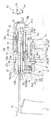
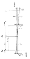
本実施形態のバリフォーカルズームレンズ鏡筒は、図1、図2に示すように、物体側から順に、第1レンズ群L1、第2レンズ群(フォーカスレンズ群)L2、第3レンズ群L3及び第4レンズ群L4を有する4群ズームレンズであり、それぞれ、第1群枠11、第2群枠(フォーカスレンズ枠)12、第3群枠13及び第4群枠14に支持されている。ズーミングに際しては、全てのレンズ群が互いの空気間隔を変化させながら光軸方向に直進移動する。第2レンズ群L2は同時にフォーカシングレンズ群であり、フォーカシング時のみ回転を伴って光軸方向に移動する。
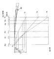
【0017】
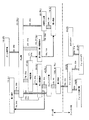
図3は、本実施形態のバリフォーカルレンズ鏡筒の動力伝達経路を理解しやすくするために、主要な鏡筒構成部材をブロックとして表した概略図である。同図において、部材名称の次の数字の後の括弧付き大文字(S)は、その部材が固定されていることを示し、同(L)は光軸方向に直進移動することを示し、同(RL)は回転しつつ光軸方向に移動することを示す。また、同図において、部材を示すボックス間を接続する矢印は、その矢印の基部側の部材が該矢印の先端部側の部材を光軸方向に直進案内していることを示し、ボックス間を接続する破線は、互いの部材が相対回転可能で光軸方向の相対移動は不能に結合されていることを示す。さらに、同図において、部材間に位置する斜めハッチングを付したボックスは、一方の部材の回転によって他方の部材を光軸方向に進退させるリードまたはカム機構を示し、横ハッチング(水平方向のハッチング)を付したボックスは、一方の部材の回転を他方に伝達する回転伝達機構を示している。
【0018】
本バリフォーカルレンズ鏡筒の固定側部材は、一眼レフカメラボディ70のマウント71に着脱されるマウント環15、このマウント環15に固定された、一部が外径に露出する外固定筒16、及び同じくマウント環15に固定された、露出しない内固定筒(固定環)17である。外固定筒16には、その前方と後方とに位置させて、ともに光軸方向位置を規制して回転のみ自在にフォーカス操作環(MF操作環)18とズーム操作環19とが支持されている。
【0019】
マウント環15の後端面には、その周方向の特定位置にカプラギヤ20の後端部が臨んでいる。このカプラギヤ20は、光軸と平行な方向に延びマウント環15の後端面及び外固定筒16の後端部の内方フランジ16aを貫通し、そのギヤ部20aが内方フランジ16aの内側に位置している。このカプラギヤ20は、周知のように、マウント環15がカメラボディ70のマウント71に装着されたとき、該カメラボディ70側のカプラギヤ71と噛み合い、該ボディ側カプラギヤ72の回転によって回転駆動される。
【0020】
外固定筒16の内方フランジ16aには、カプラギヤ20のギヤ部20aに噛み合うセクタギヤ21aを有するフォーカスギヤ21が一定角度の往復回動を可能にして支持されている。このフォーカスギヤ21は、図4、図5に示すように、外固定筒16側の複数(図では3個)の抜け止め突起16bの導入凹部21bと、抜け止め突起16bを一定角度回動可能とする円弧溝21cとを有していて、ギヤ部20aの正逆回転により、外固定筒16に対する定位置で正逆に一定角度回動する。すなわち、カプラギヤ20の回転がフォーカスギヤ21に伝達される。なお、本バリフォーカルレンズ鏡筒の使用状態では、各抜け止め突起16bが対応する導入凹部21bまで移動することはなく、抜け止め突起16bは円弧溝21cに完全に係合した状態を保つ。
【0021】
このフォーカスギヤ21には、周方向の1カ所に、フォーカスレバー挿入溝21dが形成されている。このフォーカスレバー挿入溝21dには、図6に単体形状を示すフォーカスレバー22の半径方向部22aが嵌まる。図1及び図2に示すように、この半径方向部22aは、後述するカム環23の光軸方向後端部よりも後方に位置している。フォーカスレバー22はさらに、半径方向部22aの外径側から光軸と平行な方向の前方に延びる外径腕22bと、半径方向部22aの内径側から光軸と平行な方向の前方に延びる内径腕22cとを有していて、外径腕22bは、固定ねじ22dにより、フォーカス操作環18の内面に固定されている。内径腕22cは、第2群枠12に固定した回転伝達アーム12aと光軸と平行な方向の相対移動は可能に係合し、フォーカスレバー22の回転を第2群枠12に伝達する。回転伝達アーム12aは、その一部に内径腕22cを受け入れる二股部を有するレバー状部材である。従って、フォーカス操作環18とフォーカスギヤ21とは常時等しい回動をする。つまり、カプラギヤ20を介してフォーカスギヤ21を回動させたときにはフォーカス操作環18も一緒に回動し、フォーカス操作環18を手動で回動させたときには、フォーカスギヤ21が一緒に回動し、いずれにしても、内径腕22cと回転伝達アーム12aを介して第2群枠12(第2レンズ群L2)を回動させる。
【0022】
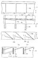
内固定筒17には、図7に示すように、フォーカスレバー22を相対回動自在に挿通させた貫通穴17aが形成されている。また、内固定筒17には、その外周面に、光軸方向及び周方向に対して傾斜した複数個(図では3個)のリード突起17bが形成されており、各リード突起17bは、カム環(レンズ駆動環、ズーム繰出環)23の内面に形成した対をなすリード用フォロア23aに係合している(挟まれている)。カム環23は、その外周面に、リード突起17bとは傾斜方向が逆の複数個(図では3個)のリード突起23bを有しており、各リード突起23bは、第1群枠11の内周面一部に形成したリード凹部11aに対して相対移動自在に嵌まっている。また内固定筒17には、その内周面に光軸と平行な方向の複数個(図では3個)の直進案内凹部17cが形成されており、各直進案内凹部17cは、第2群移動枠(中間移動枠)24の外周面に形成した光軸と平行な方向の直進案内突起24aに嵌まっている。さらに、第2群移動枠24の外周面には、直進案内突起24aとは別の複数個(図では3個)の直進案内突起24bが形成されていて、各直進案内突起24bは、第1群枠11の内周面に形成した直進案内凹部11bに嵌まっている。
【0023】
以上の内固定筒17の直進案内凹部17cと第2群移動枠24の直進案内突起24aの嵌合案内関係、第2群移動枠24の直進案内突起24bと第1群枠11の直進案内凹部11bとの嵌合案内関係により、第2群移動枠24と第1群枠11は、内固定筒17に対して回転は規制され、光軸方向の移動が可能に支持されている。つまり、第1群枠11と第2群移動枠24は、回動しない直進部材である。
【0024】
カム環23の先端部内面には、複数個(図では3個)の回動案内突起23cが形成されている。各回動案内突起23cは、第2群移動枠24の円周方向溝24cに相対回転自在にかつ光軸方向の相対移動は生じないように嵌まっている。つまり、カム環23は、第2群移動枠24と光軸方向には一緒に移動し、第2群移動枠24に対する相対回転は可能な部材である。なお、円周方向溝24cは、その一部に各回動案内突起23cを挿脱可能な複数の突起入口部24e(図では3個、図7参照)を有するが、レンズ鏡筒の使用状態では、各回動案内突起23cは対応する突起入口部24eの位置まで移動せず、円周方向溝24cと完全に嵌合している。
【0025】
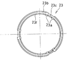
カム環23には、その内周面の一部に、光軸と平行な方向の回転伝達溝23dが形成されている。この回転伝達溝23dには、ズーム操作環19の内周面に固定したズームレバー26(図1、図2)が光軸方向の相対移動は可能にかつズーム操作環19の回転は伝達されるように嵌まっている。ズームレバー26の形状はフォーカスレバー22と似ている。カム環23は、回動が与えられると、そのリード用フォロア23aとリード突起17bとの係合関係により、光軸方向に繰り出される。ズーム操作環19は定位置で回転するのに対し、ズーム操作環19と等しい回動をするカム環23は、光軸方向への進退動作を伴う。そして、第2群移動枠24は、円周方向溝24cと回動案内突起23cの係合関係により、カム環23と光軸方向には一緒に移動するが、回動はしない。図8は、カム環23の光軸方向から見た単品図である。
【0026】
第1群枠11(第1レンズ群L1)は、ズーム操作環19を介してカム環23が回動すると、リード突起23bとリード凹部11aの関係、及び直進案内凹部11bと直進案内突起24bの関係に従って光軸方向に直進移動する。
【0027】
第2群枠12は、カムフォロア環(フォーカスガイド環)40を介して第2群移動枠24に支持されている。図1、図2に示すように、ズーム操作環19の回動操作によってカム環23に伴って第2群移動枠24が光軸方向に直進移動したとき、第2群枠12(第2レンズ群L2)は、カムフォロア環40を介して第2群移動枠24と同量だけ移動する。このとき、第2群枠12は第2群移動枠24に対して回転しない。このズーミング時の第2レンズ群L2の具体的な案内構造については後述する。
【0028】
以上で第1レンズ群L1と第2レンズ群L2に与えるズーミング用の動作が理解される。次に、第3レンズ群L3と第4レンズ群L4にズーミング用の動作を与える機構を説明する。
【0029】
カム環23には、その後端部に4群カム駆動レバー28が固定されており、この4群カム駆動レバー28は、内固定筒17に形成した逃げ溝17dを通って、内固定筒17の内径側に延びている。内固定筒17にはまた、間接的に第3群枠13を直進案内するための光軸と平行な方向の複数個(図では3個)の貫通案内穴17fが形成されている。
【0030】
各貫通案内穴17fには、第3群移動枠27に形成した直進案内を兼ねる対をなすフォロア27a(図1、図9参照)が嵌まっている。第3群移動枠27は、内固定筒17の内径に相対移動自在に嵌まっていて、貫通案内穴17fとフォロア27aにより、移動方向を光軸方向に規制されている。対をなすフォロア27aの間には、カム環23の内周面に形成したカム突起23fが嵌まっており、カム環23が回動すると、カム突起23fの形状に従って、第3群移動枠27が回転することなく光軸方向に進退する。
【0031】
第3レンズ群L3を支持した第3群枠13は、第3群移動枠27の絞支持環状部27bとの間に絞り羽根及び絞開閉環30を挟んだ状態で、この第3群移動枠27に固定されており、第3群移動枠27と一緒に光軸方向に進退する。図10、図11に示すように、第3群枠13の外周面には、光軸と平行な方向の複数個(図では3個)の直進案内突起13aと、円周方向溝13bとが形成されている。各直進案内突起13aには、第4レンズ群L4を支持した第4群枠14の内周面に形成されている直進案内溝14aが嵌まり、第4群枠14が第3群枠13に対して直進移動案内されている。
【0032】
一方、第3群枠13の外周面には、4群用カム環29が回転自在に嵌まっている。具体的には、この4群用カム環29の先端部内面に突出形成した回転案内突起29aが、第3群枠13の円周方向溝13bに対して回転のみ自在に嵌まっている。すなわち、4群用カム環29は、第3群枠13に対する相対回転は自在で光軸方向には第3群枠13と一緒に移動する。この4群用カム環29の内周面には、複数個(図では3個)の凸カム29bが形成されており、各凸カム29bは、第4群枠14の外周面に形成した対をなすフォロア突起14bに係合し(挟まれ)、4群用カム環29が回転すると、第4群枠14が光軸方向に進退する。
【0033】
第3群枠13、第4群枠14及び4群用カム環29を組むときには、まず凸カム29bとフォロア突起14bが係合するように4群用カム環29を第4群枠14と組み合わせる。続いて、4群用カム環29と第4群枠14の結合体をその軸線方向に移動させて、4群用カム環29の回転案内突起29aを、第3群枠13側に設けた突起入口部13cを通して円周方向溝13bに入れ、同時に第4群枠14の直進案内溝14aを第3群枠13の直進案内突起13aに入れる。この時点で、4群枠14は第3群枠13によって直進案内される。さらに、回転案内突起29aが突起入口部13cから離れて完全に円周方向溝13bと係合するように4群用カム環29を所定量回転させると、フォロア突起14bは凸カム29bに対し、ズーミング用の使用領域で係合する。なお、第3群枠13と4群用カム環29はズーミングに伴って相対回転するが、この使用時の相対回転角度範囲では、回転案内突起29aは常に円周方向溝13b内に完全に嵌っており、突起入口部13cの位置へは移動しない。
【0034】
4群用カム環29には、径方向外方に突出する回転伝達腕29cが形成されており、この回転伝達腕29cに、カム環23に固定されている上述の4群カム駆動レバー28が回転方向には一体に、光軸方向の相対移動は可能に係合している。従って、ズーム操作環19を回動させてその回転をカム環23、4群カム駆動レバー28から4群用カム環29に伝達すると、カム突起23fとフォロア27aとの関係で第3群移動枠27(第3群枠13、第3レンズ群L3)が光軸方向に移動し、凸カム29bとフォロア突起14bの関係で第4群枠14(第4レンズ群L4)が光軸方向に移動してズーミング用の移動軌跡が得られる。
【0035】
以上のバリフォーカルレンズ鏡筒のズーミング時の全体的な動作を、図1ないし図3を参照して簡単に説明する。ズーミングの際には、ズーム操作環19を回転させるとカム環23に回転が伝達される。カム環23は、内固定筒17との間に配したガイド機構(17b、23a)に従って、回転しながら光軸方向に移動する。このカム環23の移動(回転と光軸方向移動)による第1の作用として、第2群移動枠24も共に光軸方向へ移動する。このとき第2群枠12は回転することなく第2群移動枠24と一緒に光軸方向へ移動する。また、カム環23の移動による第2の作用として、カム環23の外周側のガイド機構(11a、23b)に従って、第1群枠11が光軸方向に所定の軌跡で移動される。また、カム環23の移動による第3の作用として、カム環23の内周側のガイド機構(23f、27a)に従って、第3群枠13が光軸方向に所定の軌跡で移動される。さらに、カム環23の移動による第4の作用として、その回転力が4群用カム環29に伝達され、この4群用カム環29と第4群枠14の間に配したガイド機構(29b、14b)に従い、第3群枠13に対して第4群枠14が光軸方向に所定の軌跡で移動する。以上から、ズーム操作環19を回転させると、第1レンズ群L1、第2レンズ群L2、第3レンズ群L3及び第4レンズ群L4がそれぞれ光軸方向に所定の軌跡で移動して、焦点距離を変化させることができる。すなわち、図3中の一点鎖線よりも上方に示す各要素がズーム系の駆動機構を構成している。なお、上記説明中のガイド機構とは、線形、非線形いずれの移動を付与するものであってもよい。
【0036】
以上のズーミングの説明は、第2群枠12(第2レンズ群L2)、第2群移動枠24、及びカムフォロア環40の関係を無視したものである。上述したように、バリフォーカルレンズは、ズーミングを行うと像面位置が変化するレンズであり、この像面位置変化を補償するために、第2レンズ群L2は、異なる焦点距離においては、同じ被写体距離の物体に対して異なる繰出量だけ繰り出して合焦させなければならない。上述したように、その際、同じ距離の被写体に合焦させるとき、異なる焦点距離に応じ、距離環の同じ回転角で異なる距離だけフォーカスレンズ群を移動させて被写体に合焦させなければならないという制約条件がある。
【0037】
この機構を得るための構成を次に説明する。第2群移動枠24と第2群枠12の間に位置するカムフォロア環40には、カム環23の内周面に固定した第2ズームレバー42が固定ねじ42aによって固定されている。ズーム操作環19の回動操作に従ってカム環23が回転(及び光軸方向移動)を行ったとき、第2ズームレバー42を介してカムフォロア環40はカム環23と同角度回転する。内固定筒17先端部には、この第2ズームレバー42を挿通させる貫通切欠部17gが形成されている。
【0038】
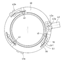
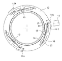
図7及び図12に示すように、第2群移動枠24の内周面には、周方向に等間隔で3本のフォーカス戻しカム(調整用カム)24dが形成されており、各フォーカス戻しカム24dは、カムフォロア環40の外周面に形成した対をなすカムフォロア突起(調整用カムフォロア)40aに係合している(挟まれている)。なお、対をなすカムフォロア突起40aが互いの周方向位置をずらせて形成されているのは、成形時の型抜きを容易にさせるという理由からである。
【0039】
またカムフォロア環40の内周面側には、周方向に等間隔で3つの球体フォロア43が保持されており、各球体フォロア43は、第2群枠12の外周面に形成したフォーカスカム溝(繰出ガイド溝)12bに嵌まっている。フォーカスカム溝12bも周方向に等間隔で3本形成されている。フォーカスカム溝12bとフォーカス戻しカム24dは同じ形状である。なお、フォーカスカム戻しカム24dは、カム環23のテレ端からワイド端の最大回転角に対応する範囲(使用領域)にのみ形成されている関係上、フォーカスカム溝12bよりも短くなっているが、フォーカスカム戻しカム24dと、これに対応するフォーカスカム溝12bの範囲は、同形状になっている。
【0040】
球体フォロア43は、カムフォロア環40に形成した半径方向の貫通溝からなる球体移動溝40bに遊びを極小にして嵌まっており、さらにカムフォロア環40の内部には、球体移動溝40bから突出する方向、すなわち第2群枠12のフォーカスカム溝12bと係合する方向に向けて球体フォロア43を付勢する付勢部材45が設けられている。
【0041】
以上の第2レンズ群L2の支持構造における、ズーミング用の動作をまず説明する。上述したように、ズーム操作環19をテレ端とワイド端の間で回転操作してカム環23が回転を伴って光軸方向に移動すると、第2群移動枠24が回転は行わずに光軸方向に同量移動する。このとき、カムフォロア環40には第2ズームレバー42を介してカム環23と同角度の回転が与えられ、フォーカスカム戻しカム24dとカムフォロア突起40aの関係により、カムフォロア環40は第2群移動枠24に対して光軸方向へ相対移動する。
【0042】
一方、第2群枠12は、フォーカスカム溝12bと球体フォロア43の嵌合によってカムフォロア環40に支持されており、カム環23によってカムフォロア環40が回転したときには、フォーカスカム溝12bと球体フォロア43の関係に従って、第2群枠12とカムフォロア環40は光軸方向に相対移動する(第2群枠12はフォーカス操作環18を回転させない状態では回転しない)。ここで、フォーカスカム溝12bはフォーカスカム戻しカム24dと同形状であるため、カムフォロア環40に対する第2群枠12の移動量及び移動方向は、該カムフォロア環40に対する第2群移動枠24の移動量及び移動方向と同じである。つまり、図1及び図2に示すように、ズーミングに際して、第2群枠12は第2群移動枠24と同量だけ光軸方向に移動され、カムフォロア環40は、第2群枠12と第2群移動枠24の両方に対して等しくその回転位置及び光軸方向位置を変化させる。上述のように、第2群移動枠24はカム環23と光軸方向に同量移動する部材であるから、ズーミングにおける2群枠12(第2レンズ群L2)の移動量は、実質的に、カム環23のリード用フォロア23aが係合する内固定筒17のリード突起17bの形状のみによって定まる(フォーカスカム戻しカム24dやフォーカスカム溝12bの影響を受けない)。
【0043】
例えば、図2のワイド端から図1のテレ端まで繰り出したときに、第2群移動枠24が移動量ΔZL(不図示)前進すると、第2群枠12も移動量ΔZL前進し、カムフォロア環40は、この移動量ΔZLからフォーカスカム戻しカム24dによる相対移動分ΔFO(不図示)を差し引いた分、すなわちΔZL-ΔFOだけ前進する。
【0044】
以上がズーミングにおける第2群枠12、第2群移動枠24、及びカムフォロア環40の関係である。続いてフォーカシングについて説明する。フォーカシングは、フォーカス操作環19の回転操作、またはカメラボディ側からのカプラギヤ20の電動駆動によって第2群枠12を回転させることで行う。第2群枠12に対しては、図3中の一点鎖線よりも下方に示すフォーカス駆動系を構成するフォーカスギヤ21、フォーカスレバー22、及び回転伝達アーム12aによって回転力が伝達される。第2群枠12は、回転すると、フォーカスカム溝12bと球体フォロア43の嵌合関係によって(フォーカスカム溝12bの形状に従って)、カムフォロア環40に対し光軸方向に相対移動する。これにより、第2群枠12に支持される第2レンズ群L2が、停止している他のレンズ群L1、L3及びL4に対して光軸方向の位置を変化させ、焦点面位置が変化する。つまりフォーカシングがなされる。なお、カムフォロア環40は、ズーム操作環19を操作しない状態では回転も光軸方向移動もせず、実質的に第2群移動枠24と同じ部材とみなすことができるので、このフォーカシングに際しての第2群枠12(第2レンズ群L2)の移動量は、フォーカスカム溝12bの形状のみによって定まる。
【0045】
上述したように、ズーミング動作を行うと第2群枠12とカムフォロア環40の相対回転位置及び光軸方向の相対位置が変化するが、これはすなわち、フォーカスカム溝12b内での球体フォロア43の嵌合位置が変化することを意味する。その結果、焦点距離を変化させると、フォーカシングに際して使用される(無限遠距離から至近距離まで合焦させるための)フォーカスカム溝12bの範囲が変化する。フォーカスカム溝12bは非線形形状であるから、その使用範囲が異なれば、第2群枠12に同じ角度の回転を与えた場合でも第2群枠12に生じる光軸方向の移動量は変化することになる。例えば、図12に示すように、ある焦点距離A’でフォーカスカム溝12b内のA位置に球体フォロア43が位置しているとき、フォーカシング動作を行わずにズーム操作環19を回転させて別の焦点距離B’にすると、球体フォロア43はB位置に移動する。ここで焦点距離A’とB’で第2群枠12に同一の回転角Δθを与えると、それぞれ使用するカム溝の範囲(形状)が相違するため、球体フォロア43とフォーカスカム溝12bの光軸方向の相対位置は、焦点距離A’では移動量ΔFAだけ変化し、焦点距離B’では異なる移動量ΔFB分変化する。つまり、焦点距離A’とB’では、第2群枠12を同一角度回転させたときの第2レンズ群L2の移動量が異なる。したがって、フォーカスカム溝12bとフォーカスカム戻しカム24dの形状を適当に設定することにより、同一のフォーカス操作環18の回転角により、2群枠12(第2レンズ群L2)を異なる距離だけ進退させ、ズーミングに伴う焦点移動を補償すると同時に被写体に合焦させることができる。
【0046】
以上のズーミング及びフォーカシング動作の説明は、同形状のフォーカスカム溝12bとフォーカスカム戻しカム24dに対し、球体フォロア43とカムフォロア突起40aが対応する同位置で係合している状態からズーミングを行い、その後フォーカシングした場合を想定したものである。一度合焦動作を行うと、フォーカスカム溝12bとフォーカスカム戻しカム24dに対する球体フォロア43とカムフォロア突起40aの相対位置が変化するので、その後のズーミング動作が若干異なる。例えば、図12において、ある焦点距離の待機状態(例えば無限遠距離に合焦する状態)において球体フォロア43とカムフォロア突起40aが周方向の同一位置Cにあると仮定する。ここで、ある有限距離の被写体に合焦させるために第2群枠12を回転させると球体フォロア43がD位置に移動するが、カムフォロア突起40aはC位置から移動せず、両者の周方向の相対位置が変化する。ここで、ズーミングに際して、カムフォロア突起40aは光軸方向の移動が内固定筒17のリード突起17b(すなわち第2群移動枠24の光軸方向位置)に規制されているが、球体フォロア43にはこのような規制がない。そのため、この状態からズーム操作環19を回転させて焦点距離を変化させると、カムフォロア環40はズーミングに際し第2群移動枠24のフォーカス戻しカム24dに沿って回転し、球体フォロア43は第2群枠12のフォーカスカム溝12に案内されて光軸方向に移動する。これにより、第2群枠12と第2群移動環24の相対位置が変化し、第2群枠12(第2レンズ群L2)は、カム環23の内固定筒17に対する回転位置により決定される焦点距離に応じた合焦位置に移動する。すなわち、ズーミングに伴う焦点移動を補償するような形状にフォーカスカム溝12bとフォーカスカム戻しカム24dを形成したことにより、ある距離の被写体に合焦する状態でズーミングを行った場合でも、その被写体に対する合焦状態を維持したまま焦点距離を変更することができる。
【0047】
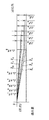
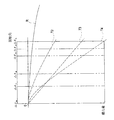
フォーカスカム溝12b及びフォーカスカム戻しカム24dの形状の決定方法の具体例を図20ないし図23を参照して説明する。フォーカス操作環18の回転角(ΔθF1〜ΔθFN)と、2群枠12(第2レンズ群L2)の繰出量(無限遠から至近距離)(ΔFS、ΔF1〜ΔF4、ΔFL)の関係を、ZS〜ZLの各焦点距離別に、無限遠撮影位置(繰出量:0)を原点にとって示すと図20に示すような変化曲線が得られる。このグラフにおいて、ZS、ZLはそれぞれ、ワイド端、テレ端における焦点距離であり、Z1ないしZ4は、フォーカスカム溝12b及びフォーカスカム戻しカム24dの形状を定めるのに適当な任意の中間焦点距離である。図20で得られた焦点距離別の繰出量の変化曲線をそれぞれ、その焦点距離に対応するズーム操作環19の回転角(ΔθS〜ΔθL)に対応させて配置すると図22のようになる。図22は、ズーム操作環19の回転角と各レンズ群の繰出量の関係、すなわち、ズーミングに伴う各レンズ群の移動軌跡(T2〜T4)をも同時に描いている。T2は第2レンズ群L2の移動軌跡、T3は第3レンズ群L3の移動軌跡、T4は第1レンズ群L1の移動軌跡である。このときの変化曲線の配置方法は、例えば、焦点距離ZSとZ1での繰出量変化曲線P、Qを配置する場合、図21に示すように、変化曲線Pの原点を、対応するズーム操作環19の回転角ΔθS(原点)の位置に合わせて配置し、続いて、変化曲線Qの原点を、対応する同回転角Δθ1の位置に配置するという手法である。以下、各焦点距離のグラフ全てに対してこのような配置をすると、2群枠12(第2レンズ群L1)の繰出量の集合グラフR0が得られる。この集合グラフR0の原点を結ぶと図23に示す連続曲線Rが得られる。なお、図22、図23において、ズーム操作環19の回転角を示す横軸は、連続曲線Rが滑らかな曲線になるように目盛りを定めている。
【0048】
図23で得られた連続曲線Rをフォーカスカム溝12b及びフォーカスカム戻しカム24dの形状とすれば、2群枠12(第2レンズ群L2)に前述の動作をさせることができる。連続曲線Rは、前述の変化曲線の原点(すなわち、2群枠12(第2レンズ群L2)の無限遠撮影位置)を結んで得られているから、無限遠距離においては焦点距離全域で2群枠12(第2レンズ群L2)の正確な合焦位置を確保できる。一方、有限距離において、連続曲線Rは近似的に描かれているため、有限撮影距離における2群枠12(第2レンズ群L2)の繰出量は誤差をもつ。そのため、フォーカス操作環18の最大回転角ΔθFNを変化させることによって、この誤差を許容誤差範囲内(被写界深度内)に収まるようにフォーカスカム溝12b及びフォーカスカム戻しカム24dの形状を設定している。よって、このようなフォーカスカム溝12b及びフォーカスカム戻しカム24dの形状により、ズーミングに応じてフォーカスカム溝12b及びフォーカスカム戻しカム24dの最大回転角ΔθFNを変化させることにより、2群枠12(第2レンズ群L2)を、無限遠距離では誤差がない正確な合焦位置に、有限距離では被写界深度内の位置に移動することができる。
【0049】
なお、AFの場合は、フォーカス操作環18をデフォーカス量に基づいた回転角だけ電動駆動すればよい。同一のデフォーカス量であれば、各焦点距離において回転角は一定である。
【0050】
本発明は、以上のバリフォーカルレンズ鏡筒において、特に第2群枠12カムフォロア環40の間に配したガイド(カム)機構に特徴を有する。このカム機構は、上述のように、フォーカスカム溝12bと球体フォロア43により構成されており、球体フォロア43は付勢部材45によってフォーカスカム溝12bと係合する方向に付勢されている。このように球状のフォロアとカム溝を係合させることで滑らかな摺動が可能になり、第2レンズ群L2に正しく上述のような移動を与えることができる。特に、本実施形態のバリフォーカルレンズ鏡筒では、フォーカシング時のみならず、ズーミング時にもフォーカスカム溝12b内での球体フォロア43の移動が生じるため、フォーカスカム溝12bの使用頻度が高い。そのため、フォーカスカム溝12bに係合するフォロアを、円滑な摺動が可能な球体フォロア43とした構成が有効である。
【0051】
球体フォロア43は金属材料によって形成してもよいし、合成樹脂の成形品としてもよい。また、球体フォロア43を受けるフォーカスカム溝12bは、第2群枠12を合成樹脂の成形品とし、この成形時に形成することができる。あるいは、フォーカスカム溝12bを含めて第2群枠12を金属材料で形成してもよい。または、フォーカスカム溝12bを含む一部を金属材料で形成し、当該カム溝部分を第2群枠12の外周面に固定するような構造でもよい。基本的に、成形による製造部分を多くすれば製造コストを抑えることができ、摺動部分に金属を多く用いれば強度や摺動円滑性の面で有利になる。
【0052】
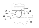
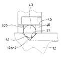
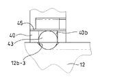
図13ないし図15に示すように、フォーカスカム溝12bの断面形状は様々な態様とすることができる。図13は断面が台形状のフォーカスカム溝12b-1、図14は断面がV字状のフォーカスカム溝12b-2、図15は断面が部分円形状のフォーカスカム溝12b-3を示している。いずれのフォーカスカム溝12b-1、12b-2、及び12b-3も、深さが浅くなるにつれて(図中の上方に向かうにつれて)徐々にその開口幅を大きくするようになっている。図13の台形状断面のフォーカスカム溝12b-1と、図14のV字状断面のフォーカスカム溝12b-2に対しては、球体フォロア43は、対をなす2つの傾斜面50または51に対して点状の領域で接し、各フォーカスカム溝の底部には接しない。台形状断面のフォーカスカム溝12b-1とV字状断面のフォーカスカム溝12b-2では、前者の方がカム溝底部の位置が浅いので、第2群枠12の肉厚を抑えて小型化を図ることができる。また、図15の部分円形状のフォーカスカム溝12b-3は、その内面形状が球体フォロア43の外面に沿う形状を有しているため、球体フォロア43と線状(円弧状)の領域で接触する。そのため、球体フォロア43との接触領域が増大し、より安定した保持、摺動案内がが可能になる。
【0053】
本実施形態のガイド(カム)機構はさらに、付勢部材45によって、球体フォロア43をフォーカスカム溝12bとの係合方向へ付勢しているため、第2レンズ群L2の倒れや位置ずれを防ぐことができる。具体的には、まず、この付勢部材45によって、各フォーカスカム溝12bに対する球体フォロア43のガタ除去を行うことができる。さらに、球体フォロア43は周方向に120度の等間隔で3つ設けられており、各付勢部材45は各球体フォロア43をフォーカスカム溝12bと係合する方向、すなわち鏡筒内径方向に付勢しているため、第2群枠12は、3点の支持箇所から均等に光軸中心に寄せる押圧力を受けることになる。これにより、第2群枠12の芯位置(第2レンズ群L2の光軸位置)が正確に出され、第2レンズ群L2の偏心を防ぐことができる。また、上述のように、各フォーカスカム溝12bに対する球体フォロア43のガタが除去されているため、このガタが除去された3点で支持される第2群枠12の、光軸に対する倒れや光軸方向への位置ずれを防ぐことができる。
【0054】
図16ないし図19に示すように、付勢部材45は様々な態様とすることができる。図16は、片持ち状の板ばねとして形成した付勢部材45-1を示している。カムフォロア環40には、その後端面に開口するように3つのばね支持穴55が形成されており、各ばね支持穴55内には、対をなすばね挟着凸部56、57が設けられている。ばね挟着凸部56、57の間隔は、板ばね状の付勢部材45-1を保持可能なように設定されており、この挟着凸部56、57によって付勢部材45-1の一端部付近を挟着させることで、付勢部材45-1はカムフォロア環40に固定される。該固定状態において、付勢部材45-1の他端部である自由端部が球体フォロア43に当接し、内径方向に押し込む。
【0055】
図17は、両端部がカムフォロア環40に固定された両持ち状の板ばねとして形成した付勢部材45-2を示している。図16の態様と異なり、カムフォロア環40の後端面に開口する3つのばね支持穴58内には、対をなすばね挟着凸部59、60が2組設けられている。各組のばね挟着凸部59、60には、板ばね状の付勢部材45-2の一端部と他端部が挟着保持されており、該挟着保持によって付勢部材45-2はカムフォロア環40に固定される。付勢部材45-2は、該固定状態でその中間部分が球体フォロア43に当接して内径方向に押し込んでいる。
【0056】
この図17と上述の図16の態様では、付勢部材45(45-1、45-2)を板ばね状とし、カムフォロア環40側に該板ばねの挟着部を設けたことにより、付勢部材を固定するためのねじやテープを別途備える必要がなく、製造コストを抑えることができる。また、板ばね状の付勢部材45(45-1、45-2)をばね支持穴55、58に差し込むだけで組み付けが完了するので、組立及び分解作業性にも優れる。なお、図17に示す両持ち板ばねの態様の方が、付勢力を付与するための曲げ量を小さくすることができるので、鏡筒半径方向における配置スペースを抑え、カムフォロア環40の肉厚を抑えることが容易になる。板ばね状の付勢部材45-1、45-2は、強度面からは金属材料で形成することが好ましいが、十分な付勢力及び強度が得られれば合成樹脂の成型品としてもよい。
【0057】
図18は、カムフォロア環40自体に弾性変形可能な薄板状の付勢部材(付勢部)45-3を形成した態様を示す。カムフォロア環40はこの付勢部材45-3部分が薄肉に形成されており、付勢部材45-3の内面側が球体フォロア43に当接している。鏡筒を組んだ状態では、球体フォロア43によって付勢部材45-3が外径方向に押されて若干量弾性変形し、その復元力によって球体フォロア43を内径方向に押し込む。付勢部材45-3は、カムフォロア環40を合成樹脂の成形品とし、その一部として一体に成形することができる。あるいは、カムフォロア環40を金属材料から形成し、その一部をなす薄肉板ばね状部として形成することもできる。この図18の構成では、付勢部材を単独部品としなくてよいので、部品点数を減らすことができる。
【0058】
図19は、付勢部材45を圧縮コイルばね状の付勢部材45-4とした態様を示す。カムフォロア環40内には、このコイルばね状の付勢部材45-4を収納するコイルばね収納部61が形成され、該付勢部材45-4の一端部が該収納部61の底面に当接し、他端部が球体フォロア43に当接している。なお、図19の実施形態では、カムフォロア環40の球体移動溝40b’は半径方向の貫通溝でなく、コイルばね収納部61を一部として含んだ有底穴となっている。コイル状の付勢部材45-4は鏡筒半径方向の伸縮可能であり、鏡筒を組んだときには、若干縮められた状態で球体フォロア43を内径方向に押し込む。
【0059】
以上のように、本実施形態のバリフォーカルレンズ鏡筒では、フォーカスレンズ群のガイド部分としてガイド溝と球状フォロアの係合を用い、さらに球状フォロアを該係合方向に付勢する付勢部材を設けたので、フォーカスレンズ群を正しく円滑に移動させ、かつその倒れや位置ずれを防ぐことができる。また、本実施形態では、フォーカス操作環18から第2群枠12(フォーカスレンズ枠)に回転伝達を行うフォーカスレバー22を、カム環23の後方を迂回する形状としたため、カム環23における強度や遮光性が損なわれることがない。また、このフォーカスレバー22は周方向に一つのみ設けられており鏡筒のコンパクト化に寄与している。そして、球状フォロアとガイド溝とからなるフォーカスレンズ群のガイド構造によれば、このような一つのフォーカスレバー22によって駆動力を与えたとき、フォーカスレンズ群に倒れを生じさせることなく円滑に駆動させることができる。
【0060】
以上、図示実施形態を参照して本発明を説明したが、本発明は実施形態に限定されるものではない。例えば、実施形態ではフォーカスレンズ枠(第2群枠12)側にフォーカスガイド溝(フォーカスカム溝12b)が形成され、該フォーカスレンズ枠を支持するフォーカスガイド環(カムフォロア環40)側に球体のフォロアが設けられるとしたが、この関係は逆であってもよい。
【0062】
【発明の効果】
以上のように、本発明によれば、バリフォーカルレンズ鏡筒におけるフォーカスレンズ群の倒れや光軸方向の位置ずれを防ぎ、かつ円滑にフォーカスレンズ群を案内して、安定した像性能を得ることができる。
【図面の簡単な説明】
【図1】本発明によるバリフォーカルズームレンズ鏡筒の一実施形態を示す、テレ端へのズーミング状態を示す上半断面図である。
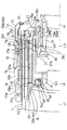
【図2】同ワイド端へのズーミング状態を示す上半断面図である。
【図3】実施形態のバリフォーカルズームレンズ鏡筒の構成部材相互の動力伝達経路やガイドの関係を概念的に示す図である。
【図4】フォーカスギヤの単体の正面図である。
【図5】図4の側面図である。
【図6】フォーカスレバーの単体の斜視図である。
【図7】第1群枠、第2群移動枠、カム環及び内固定筒の関係を示す展開分解図である。
【図8】カム環の光軸方向から見た単品図である。
【図9】カム環、内固定筒及び第3群移動枠の関係を示す展開分解図である。
【図10】第3群枠、第4群枠及び4群用カム環の関係を示す展開分解図である。
【図11】同じく第3群枠、第4群枠及び4群用カム環の関係を示す背面図である。
【図12】第2群移動枠、カムフォロア環及び第2群枠の関係を示す展開分解図である。
【図13】フォーカスカム溝と球体フォロアの係合部分の一実施形態を示す、第2群枠とカムフォロア環の断面図である。
【図14】フォーカスカム溝と球体フォロアの係合部分の異なる実施形態を示す、第2群枠とカムフォロア環の断面図である。
【図15】フォーカスカム溝と球体フォロアの係合部分のさらに異なる実施形態を示す、第2群枠とカムフォロア環の断面図である。
【図16】球体フォロアを付勢する付勢部材の一実施形態を示す、カムフォロア環の背面図である。
【図17】球体フォロアを付勢する付勢部材の異なる実施形態を示す、カムフォロア環の背面図である。
【図18】球体フォロアを付勢する付勢部材の異なる実施形態を示す、カムフォロア環の背面図である。
【図19】球体フォロアを付勢する付勢部材のさらに異なる実施形態を示す、カムフォロア環と第2群枠の断面図である。
【図20】フォーカス操作環の回転角と、2群枠(第2レンズ群)の繰出量(無限遠から至近距離)の関係を各焦点距離別に示すグラフ図である。
【図21】図20で得られた各焦点距離別の曲線を、その原点が各焦点距離毎のズーム操作環の回転角と一致するように配置する手法を示す図である。
【図22】各焦点距離別のズーム操作環の回転角に対する2群枠の繰出量の関係を図21に示す手法で配置した集合グラフを示す図である。
【図23】図22の集合グラフの原点を結んで得た連続曲線を示すグラフ図である。
【符号の説明】
11 第1群枠
11a リード凹部
11b 直進案内凹部
12 第2群枠(フォーカスレンズ枠)
12a 回転伝達アーム
12b(12b-1 12b-2 12b-3) フォーカスカム溝(繰出ガイド溝)
13 第3群枠
13a 直進案内突起
13b 円周方向溝
13c 突起入口部
14 第4群枠
14a 直進案内溝
14b フォロア突起
15 マウント環
16 外固定筒
16a 内方フランジ
16b 抜け止め突起
17 内固定筒(固定環)
17a 貫通穴
17b リード突起
17c 直進案内凹部
17d 逃げ溝
17f 貫通案内穴
18 フォーカス操作環(MF操作環)
19 ズーム操作環
20 カプラギヤ
20a ギヤ部
21 フォーカスギヤ
21a セクタギヤ
21b 導入凹部
21c 円弧溝
21d フォーカスレバー挿入溝
22 フォーカスレバー
22a 半径方向部
22b 外径腕
22c 内径腕
22d 固定ねじ
23 カム環(レンズ駆動環、ズーム繰出環)
23a リード用フォロア
23b リード突起
23c 回動案内突起
23d 回転伝達溝
23f カム突起
24 第2群移動枠(中間移動枠)
24a 直進案内突起
24b 直進案内突起
24c 円周方向溝
24d フォーカス戻しカム(調整用カム)
24e 突起入口部
26 ズームレバー
27 第3群移動枠
27a フォロア
27b 絞支持環状部
28 4群カム駆動レバー
29 4群用カム環
29a 回転案内突起
29b 凸カム
29c 回転伝達腕
40 カムフォロア環(フォーカスガイド環)
40a カムフォロア突起(調整用カムフォロア)
40b 40b’ 球体移動溝
42 第2ズームレバー
43 球体フォロア
45(45-1 45-2 45-3 45-4) 付勢部材
50 51 傾斜面
55 58 ばね支持穴
56 57 59 60 ばね挟着凸部
61 コイルばね収納部
70 カメラボディ
71 マウント
72 カプラギヤ
L1 第1レンズ群
L2 第2レンズ群(フォーカスレンズ群)
L3 第3レンズ群
L4 第4レンズ群[0001]
【Technical field】
The present invention relates to a varifocal lens mirror.In a tubeRelated.
[0002]
[Prior art and its problems]
In order to move the lens (group) in the optical axis direction for the purpose of focusing or the like in an optical device, a structure in which a cam or lead is provided on one of a pair of relatively rotatable annular members and a cam follower or lead follower is provided on the other is provided. Are known. Due to the fitting relationship between these cams and leads and the follower, the pair of annular members relatively move in the optical axis direction when they are relatively rotated. As cams, leads and followers, there are known structures in which grooves and protrusions are fitted or protrusions are fitted together. Since this causes positional displacement, it is desired to stabilize the image performance by eliminating backlash as much as possible. In order to move the lens correctly, it is preferable that the cam and the lead slide as smoothly as possible.
[0003]
Also known is a varifocal lens defined as a lens whose focal plane moves when the focal length is changed. In the varifocal lens, when the focal length is changed, the extension position of the focus lens group for focusing on a subject at the same distance changes. With an autofocus camera, it is only necessary to determine the extension position of the focus lens group (the amount of movement from the standby position) in consideration of the movement of the focal plane when the focal length changes (so as to compensate). Even with a single-lens reflex camera, the focal plane movement (blurring) when the focal length is changed can be viewed through the viewfinder, and the distance ring (focus ring) can be rotated to eliminate blurring. No problem.
[0004]
However, for a single-lens reflex camera, it is necessary to engrave (display) an imaging distance scale on the distance ring, and it is necessary to focus on a subject at the distance indicated by the imaging distance scale at any focal length. In other words, when focusing on a subject at the same distance, the focus lens group must be moved by a different distance at the same rotation angle of the distance ring from the infinity shooting position, for example, according to different focal lengths. I must. That is, in terms of operation, the same operability as a zoom lens whose focal plane does not move even when the focal length is changed is required. In this sense, there is no practical difference between the varifocal lens barrel and the zoom lens barrel. In general, such a varifocal lens barrel is not only complicated in structure, but also has a focus cam that changes the extension position of the focus lens group per unit rotation angle of the distance ring according to the change in focal length, and zooming. There is a problem that it is difficult to remove the mutual interference (influence) with the zoom cam. In order to solve this problem, the present applicant has proposed a varifocal lens barrel capable of zooming without interference between the focus cam and the zoom cam (Japanese Patent Application No. 2000-201928, unpublished). The concept of the prior invention will be described in the following description of the present embodiment. In such a varifocal lens barrel, the influence of the focus lens group on the image performance due to the positional deviation or the tilt of the focus lens group is particularly large. It is desirable to stabilize the image performance by eliminating backlash in the support guide mechanism as much as possible. It is desirable to move the focus lens group smoothly.
[0005]
OBJECT OF THE INVENTION
The present invention, BaThe objective is to obtain stable image performance by preventing the focus lens group from tilting or shifting in the optical axis direction in the refocal lens barrel and smoothly guiding the focus lens group.The
[0006]
SUMMARY OF THE INVENTION
The present invention has a plurality of variable magnification lens groups movable in the direction of the optical axis for changing the focal length, and one of the lens groups has both a variable magnification and a focus adjustment function, and is the same at different focal lengths. A focus operation ring that is rotated in a varifocal lens barrel that is a focus lens group in which a focus extension position with respect to a subject distance changes;Located inside the focus operation ring in the radial direction centered on the optical axis, and supports the focus lens groupFocus lens frame;A lens drive ring that is positioned between the focus operation ring and the focus lens frame in the radial direction centered on the optical axis and drives the variable magnification lens group other than the focus lens group; an outer side fixed to the inner surface side of the focus operation ring A radial arm, an inner diameter arm that is movable relative to the focus lens frame in the optical axis direction and cannot be rotated relative to the optical axis, and behind the rear end of the lens drive ring in the optical axis direction. A focus lever provided in the circumferential direction having a radial portion connecting the rear end portions in the optical axis direction of the inner diameter arm and the outer diameter arm, and transmitting the rotation of the focus operation ring to the focus lens frame; FFocus guide ring located outside the focus lens frame: a focus cam having a non-linear shape provided on one of the outer surface of the focus lens frame and the inner surface of the focus guide ring to compensate for image plane movement due to focal length change; A follower provided on the other of the outer surface and the inner surface of the focus guide ring, engaged with the focus cam and rotated in the optical axis direction according to the shape of the focus cam; A focus cam use area adjustment mechanism that changes the engagement position of the focus cam and the follower according to the distance change, and changes the amount of movement of the focus lens group per fixed rotation angle of the focus operation ring according to the focal length. However, the focus cam consists of a bottomed focus cam groove. It consists of a spherical follower that fits movably in a radial sphere movement groove formed in the focus lens frame or focus guide ring, and that fits in this bottomed focus cam groove. An urging member for urging in a direction engaging with the focus cam groove is provided. According to the guide structure having the focus cam groove, the spherical follower, and the urging member, the focus lens group in the varifocal lens barrel can be correctly and smoothly moved, and the tilting and displacement thereof can be prevented.
[0007]
In this varifocal lens barrel, a zoom operation ring that is rotated independently of the focus operation ring; an intermediate movement frame that is guided in the optical axis direction and supports the focus lens frame via the focus guide ring;As a lens drive ring located between the focus operation ring and the focus lens frame,The zoom operation ring includes a zoom feed ring that moves a plurality of variable magnification lens groups and intermediate movement frames in the optical axis direction along a predetermined locus by rotating the zoom operation ring. A rotation transmission member that is integrally rotated in the rotation direction with the zoom feeding ring and is relatively movable in the optical axis direction; and a focus provided on one and the other of the opposed peripheral surfaces of the intermediate movement frame and the focus guide ring It is preferable to have an adjustment cam having the same shape as the cam groove and an adjustment cam follower engaged with the adjustment cam. In this configuration, when the adjustment cam follower and the spherical follower are located at the same position with respect to the adjustment cam and the focus cam groove having the same shape, the focus guide ring isDeliveryThis focus guide is guided by the focus cam groove and the adjustment cam according to the rotation of the ring, and rotates relative to both the focus lens frame and the intermediate movement frame by the same angle and moves in the optical axis direction by the same amount. The engagement position of the focus cam groove and the spherical follower can be changed by the operation of the ring.
[0008]
Further, the varifocal lens barrel of the present invention further includes a fixed ring, and the zoom feeding ring is supported in such a manner that the fixed ring moves in the direction of the optical axis when rotated, and the intermediate moving frame is It is preferable that the zoom feed ring is supported in such a manner that relative rotation is freely possible and relative movement in the optical axis direction does not occur.
[0009]
For example, the focus cam groove can be formed on the outer surface of the focus lens frame, and the spherical follower can be provided on the inner surface of the focus guide ring.
[0012]
The varifocal lens mirror of the present invention as described aboveIn a tubeThe focus guidegroove,Each of the spherical follower and the urging member is preferably provided at equal intervals in the circumferential direction.
[0013]
Further, the focus cam groove of the varifocal lens barrel of the present inventionIsAs the depth becomes shallower, the trapezoidal cross-sectional groove, V-shaped cross-sectional groove, and partial circular cross-sectional groove that gradually increase the opening width can be used.
[0014]
In addition, the varifocal lens mirror of the present inventionIn a tubeThe biasing member can be a coil spring, a cantilevered leaf spring, a double-supported leaf spring, or the like. When the biasing member is a leaf spring, the focus lensFrame andFocus guideRingOn the other hand, it is preferable to form a clamping part that clamps and holds the leaf spring-like urging member. The biasing member is a focus lens.Frame andFocus guideRingOn the other hand, it is good also as an elastic thin plate-shaped part which is formed as a part of the elastic deformable part.
[0015]
Varifocal lens mirror of the present inventionIn a tubeThe spherical follower and the biasing member can be formed of, for example, a metal material or a synthetic resin material. Focus camGroove, Focus guideRingFocus lensFrame andIt can be molded integrally with a synthetic resin material, or at least this focus guideRingOnly the portion may be formed of a metal material.
[0016]
DETAILED DESCRIPTION OF THE INVENTION
As shown in FIGS. 1 and 2, the varifocal zoom lens barrel of the present embodiment includes a first lens group L1, a second lens group (focus lens) in order from the object side.group)4 is a four-unit zoom lens having L2, a third lens unit L3, and a fourth lens unit L4, and each includes a
[0017]
FIG. 3 is a schematic view showing main barrel constituent members as blocks in order to facilitate understanding of the power transmission path of the varifocal lens barrel of the present embodiment. In the figure, a capital letter (S) in parentheses after the number next to the member name indicates that the member is fixed, and (L) indicates that the member moves straight in the optical axis direction. RL) indicates movement in the optical axis direction while rotating. In addition, in the same figure, an arrow connecting between the boxes indicating the members indicates that the member on the base side of the arrow is guiding the member on the tip side of the arrow straightly in the optical axis direction. The connecting broken line indicates that the members are coupled to each other such that the relative rotation is possible and the relative movement in the optical axis direction is impossible. Furthermore, in the same figure, the box with diagonal hatching located between the members shows a lead or cam mechanism that causes the other member to advance and retreat in the optical axis direction by rotation of one member. Lateral hatching (horizontal hatching) The box marked with indicates a rotation transmission mechanism that transmits the rotation of one member to the other.
[0018]
The fixed-side member of the varifocal lens barrel includes a
[0019]
On the rear end surface of the
[0020]
A
[0021]
The
[0022]
As shown in FIG. 7, the inner fixed
[0023]
The above-mentioned fitting guide relationship between the
[0024]
A plurality (three in the figure) of rotation guide
[0025]
The
[0026]
In the first group frame 11 (first lens group L1), when the
[0027]
The
[0028]
Thus, the zooming operation given to the first lens unit L1 and the second lens unit L2 is understood. Next, a mechanism for giving the zooming operation to the third lens unit L3 and the fourth lens unit L4 will be described.
[0029]
A fourth group
[0030]
Each through
[0031]
The third
[0032]
On the other hand, a fourth
[0033]
When assembling the
[0034]
The fourth
[0035]
The overall operation during zooming of the above varifocal lens barrel will be briefly described with reference to FIGS. During zooming, rotation of the
[0036]
In the above description of zooming, the relationship between the second group frame 12 (second lens group L2), the second
[0037]
A configuration for obtaining this mechanism will be described next. A
[0038]
As shown in FIGS. 7 and 12, three focus return cams (adjustment cams) 24d are formed on the inner peripheral surface of the second
[0039]
Further, three
[0040]
The
[0041]
The zooming operation in the support structure for the second lens unit L2 will be described first. As described above, when the
[0042]
On the other hand, the
[0043]
For example, when the second
[0044]
The above is the relationship between the
[0045]
As described above, when the zooming operation is performed, the relative rotational position of the
[0046]
The above description of the zooming and focusing operations is performed from the state where the
[0047]
A specific example of the method of determining the shapes of the
[0048]
If the continuous curve R obtained in FIG. 23 is formed into the shape of the
[0049]
In the case of AF, the
[0050]
The present invention is characterized in the guide (cam) mechanism disposed between the
[0051]
The
[0052]
As shown in FIGS. 13 to 15, the cross-sectional shape of the
[0053]
Further, since the guide (cam) mechanism of the present embodiment urges the
[0054]
As shown in FIGS. 16 to 19, the urging
[0055]
FIG. 17 shows an urging member 45-2 formed as a double-supported leaf spring whose both ends are fixed to the
[0056]
17 and FIG. 16 described above, the urging member 45 (45-1 and 45-2) is shaped like a leaf spring, and a clamping portion for the leaf spring is provided on the
[0057]
FIG. 18 shows a mode in which a thin plate-like biasing member (biasing portion) 45-3 that can be elastically deformed is formed on the
[0058]
FIG. 19 shows an embodiment in which the urging
[0059]
As described above, the present embodimentBali FocalIn the lens barrel,focusBecause the guide groove and the spherical follower are used as the guide portion of the lens group, and the biasing member that biases the spherical follower in the engaging direction is provided.focusIt is possible to move the lens group correctly and smoothly, and to prevent the lens group from falling or misaligned.In the present embodiment, the
[0060]
Although the present invention has been described with reference to the illustrated embodiments, the present invention is not limited to the embodiments. For example,In the embodiment, a focus guide groove (focus
[0062]
【The invention's effect】
As described above, according to the present invention, the focus lens group in the varifocal lens barrel is prevented from being tilted or displaced in the optical axis direction, and the focus lens group is smoothly guided to obtain stable image performance. CanThe
[Brief description of the drawings]
FIG. 1 is according to the present invention.Bali FocalIt is an upper half sectional view showing a zooming state to a tele end showing an embodiment of a zoom lens barrel.
FIG. 2 is an upper half sectional view showing a zooming state toward the wide end.
FIG. 3 shows the embodiment.Bali FocalIt is a figure which shows notionally the relationship of the motive power transmission path | route between the structural members of a zoom lens barrel, and a guide.
FIG. 4 is a front view of a single focus gear.
FIG. 5 is a side view of FIG. 4;
FIG. 6 is a perspective view of a single focus lever.
FIG. 7 is an exploded exploded view showing a relationship among a first group frame, a second group moving frame, a cam ring, and an inner fixed cylinder.
FIG. 8 is a single product view as seen from the optical axis direction of the cam ring.
FIG. 9 is an exploded exploded view showing the relationship among the cam ring, the inner fixed cylinder, and the third group moving frame.
FIG. 10 is an exploded exploded view showing a relationship among a third group frame, a fourth group frame, and a fourth group cam ring.
FIG. 11 is a rear view showing the relationship among the third group frame, the fourth group frame, and the fourth group cam ring.
FIG. 12 is an exploded exploded view showing a relationship among a second group moving frame, a cam follower ring, and a second group frame.
FIG. 13 is a cross-sectional view of a second group frame and a cam follower ring showing an embodiment of an engagement portion between a focus cam groove and a spherical follower.
FIG. 14 is a cross-sectional view of a second group frame and a cam follower ring showing different embodiments of the engagement portion between the focus cam groove and the spherical follower.
FIG. 15 is a cross-sectional view of a second group frame and a cam follower ring showing still another embodiment of the engagement portion between the focus cam groove and the spherical follower.
FIG. 16 is a rear view of a cam follower ring showing an embodiment of a biasing member that biases a spherical follower.
FIG. 17 is a rear view of a cam follower ring showing different embodiments of a biasing member that biases a spherical follower.
FIG. 18 is a rear view of a cam follower ring showing different embodiments of a biasing member that biases a spherical follower.
FIG. 19 is a cross-sectional view of a cam follower ring and a second group frame, showing still another embodiment of a biasing member that biases a spherical follower.
FIG. 20 is a graph showing the relationship between the rotation angle of the focus operation ring and the amount of extension of the second group frame (second lens group) (from the infinity to the closest distance) for each focal length.
FIG. 21 is a diagram showing a method of arranging the curves for each focal length obtained in FIG. 20 so that the origin coincides with the rotation angle of the zoom operation ring for each focal length.
FIG. 22 is a diagram showing a set graph in which the relationship of the amount of extension of the second group frame with respect to the rotation angle of the zoom operation ring for each focal length is arranged by the method shown in FIG.
23 is a graph showing a continuous curve obtained by connecting the origins of the collective graph of FIG.
[Explanation of symbols]
11 First group frame
11a Lead recess
11b Straight guide recess
12 Second group frame (focus lensframe)
12a Rotation transmission arm
12b (12b-1 12b-2 12b-3) Focus cam groove (feeding guide groove)
13 Third group frame
13a Straight running guide protrusion
13b Circumferential groove
13c Protrusion entrance
14 4th group frame
14a Straight running guide groove
14b Follower protrusion
15 Mount ring
16 Outer fixed cylinder
16a Inner flange
16b Retaining protrusion
17 Inner fixed cylinder (fixed ring)
17a Through hole
17b Lead protrusion
17c Straight guide recess
17d escape groove
17f Through guide hole
18 Focus operation ring (MF operation ring)
19 Zoom control ring
20 Coupler gear
20a Gear part
21 Focus gear
21a Sector gear
21b Introduction recess
21c Arc groove
21d Focus lever insertion groove
22 Focus lever
22a Radial direction part
22b Outer diameter arm
22c inner diameter arm
22d fixing screw
23 Cam ring (Lens drive ring,Zoom out ring)
23a Lead follower
23b Lead protrusion
23c Rotation guide protrusion
23d Rotation transmission groove
23f Cam projection
24 Second group moving frame (intermediate moving frame)
24a Straight guide protrusion
24b Straight guide protrusion
24c Circumferential groove
24d Focus return cam (Adjustment cam)
24e Projection entrance
26 Zoom lever
27 Third group moving frame
27a Follower
27b Aperture support ring
28 4th group cam drive lever
29 4-group cam ring
29a Rotation guide protrusion
29b Convex cam
29c Rotation transmission arm
40 Cam Follower Ring (Focus Guidering)
40a Cam follower protrusion (adjustment cam follower)
42 Second zoom lever
43 Sphere Follower
45 (45-1 45-2 45-3 45-4) Biasing member
50 51 inclined surface
55 58 Spring support hole
56 57 59 60 Spring clamping convex part
61 Coil spring storage
70 camera body
71 mount
72 Coupler gear
L1 first lens group
L2 Second lens group (focus lensgroup)
L3 Third lens group
L4 4th lens group
Claims (19)
回転操作されるフォーカス操作環;
光軸を中心とする半径方向においてフォーカス操作環の内側に位置し、上記フォーカスレンズ群を支持するフォーカスレンズ枠;
光軸を中心とする半径方向においてフォーカス操作環とフォーカスレンズ枠の間に位置し、フォーカスレンズ群以外の上記変倍レンズ群を駆動するレンズ駆動環;
フォーカス操作環の内面側に固定される外径腕と、フォーカスレンズ枠に対して光軸方向に相対移動可能かつ光軸を中心とする相対回動は不能に係合する内径腕と、上記レンズ駆動環の光軸方向後端部の後方で内径腕と外径腕のそれぞれの光軸方向後端部を接続する半径方向部とを有し、フォーカス操作環の回転をフォーカスレンズ枠に伝達する、円周方向に一つ設けたフォーカスレバー;
フォーカスレンズ枠の外側に位置するフォーカスガイド環;
フォーカスレンズ枠の外面とフォーカスガイド環の内面の一方に設けた、焦点距離変化による像面移動を補償する非線形形状を有するフォーカスカム;
フォーカスレンズ枠の外面とフォーカスガイド環の内面の他方に設けた、このフォーカスカムと係合し、上記フォーカス操作環により回転駆動されるフォーカスレンズ枠を該フォーカスカムの形状に従って光軸方向に移動させるフォロア;及び
焦点距離変化に応じて上記フォーカスカムとフォロアの係合位置を変化させ、フォーカス操作環の一定の回転角あたりのフォーカスレンズ群の移動量を焦点距離に応じて変化させるフォーカスカム使用域調整機構;
を有し、
上記フォーカスカムは有底のフォーカスカム溝からなっており、
上記フォロアは、上記フォーカスレンズ枠またはフォーカスガイド環に形成した半径方向の球体移動溝に移動自在に嵌まり、さらにこの有底のフォーカスカム溝に嵌まる、球体からなるフォロアからなっており、
この球体フォロアを有底のフォーカスカム溝と係合する方向へ付勢する付勢部材を備えたことを特徴とするバリフォーカルレンズ鏡筒。It has a plurality of variable magnification lens groups that are movable in the optical axis direction to change the focal length, and one of the lens groups has both a variable magnification and a focus adjustment function. In a varifocal lens barrel that is a focus lens group in which the focus extension position changes,
Focus control ring that is rotated;
A focus lens frame that is positioned inside the focus operation ring in the radial direction about the optical axis and supports the focus lens group ;
A lens drive ring that is positioned between the focus operation ring and the focus lens frame in the radial direction about the optical axis, and that drives the variable magnification lens group other than the focus lens group;
An outer diameter arm fixed to the inner surface side of the focus operation ring, an inner diameter arm which is movable relative to the focus lens frame in the optical axis direction and cannot be rotated relative to the optical axis, and the lens It has a radial portion connecting the rear end portions in the optical axis direction of the inner diameter arm and the outer diameter arm behind the rear end portion in the optical axis direction of the drive ring, and transmits the rotation of the focus operation ring to the focus lens frame. , One focus lever in the circumferential direction;
Focus guide ring located outside the full Okasurenzu frame;
A focus cam having a non-linear shape which is provided on one of the outer surface of the focus lens frame and the inner surface of the focus guide ring and compensates for image plane movement due to a change in focal length;
The focus lens frame that engages with the focus cam provided on the other of the outer surface of the focus lens frame and the inner surface of the focus guide ring and is driven to rotate by the focus operation ring moves in the optical axis direction according to the shape of the focus cam. A follower; and a focus cam use range in which the engagement position of the focus cam and the follower is changed in accordance with a change in focal length, and the amount of movement of the focus lens group per fixed rotation angle of the focus operation ring is changed in accordance with the focal length. Adjustment mechanism;
Have
The focus cam consists of a bottomed focus cam groove,
The follower is a follower made of a sphere that fits movably in a radial sphere moving groove formed in the focus lens frame or the focus guide ring, and further fits in the bottomed focus cam groove.
A varifocal lens barrel comprising a biasing member that biases the spherical follower in a direction to engage with a bottomed focus cam groove.
上記フォーカス操作環とは独立して回転操作されるズーム操作環;及び
光軸方向に案内され、上記フォーカスガイド環を介してフォーカスレンズ枠を支持した中間移動枠;
を備え、
上記レンズ駆動環として、ズーム操作環の回転操作により、上記複数の変倍レンズ群と上記中間移動枠とを所定の軌跡で光軸方向に移動させるズーム繰出環を備え、
上記フォーカスカム使用域調整機構は、
上記フォーカスガイド環を、上記ズーム繰出環と回転方向に一体に回動させ光軸方向には相対移動可能とさせる回転伝達部材;及び
上記中間移動枠とフォーカスガイド環の対向する周面の一方と他方に設けた、上記フォーカスカム溝と同形状の調整用カムと、この調整用カムと係合する調整用カムフォロア;
を有し、
同形状の上記調整用カムとフォーカスカム溝に対し、調整用カムフォロアと球体フォロアが同位置に位置するとき、上記フォーカスガイド環は、上記ズーム繰出環の回転に応じて該フォーカスカム溝と調整用カムとに案内され、フォーカスレンズ枠と中間移動枠の両方に対して同角度相対回転すると共に光軸方向に同量相対移動し、
このフォーカスガイド環の動作により、上記フォーカスカム溝と球体フォロアの係合位置が変化するバリフォーカルレンズ鏡筒。The varifocal lens barrel according to claim 1, further comprising:
A zoom operation ring that is rotated independently of the focus operation ring; and an intermediate movement frame that is guided in the optical axis direction and supports the focus lens frame via the focus guide ring;
With
As the lens drive ring, a zoom extension ring that moves the plurality of variable magnification lens groups and the intermediate movement frame in the optical axis direction along a predetermined locus by rotating the zoom operation ring,
The focus cam usage range adjustment mechanism
A rotation transmission member that rotates the focus guide ring integrally with the zoom feeding ring in the rotation direction and allows relative movement in the optical axis direction; and one of the opposed peripheral surfaces of the intermediate movement frame and the focus guide ring; An adjustment cam having the same shape as the focus cam groove provided on the other side, and an adjustment cam follower engaged with the adjustment cam;
Have
When the adjustment cam follower and the spherical follower are positioned at the same position with respect to the adjustment cam and the focus cam groove having the same shape, the focus guide ring and the focus cam groove are adjusted according to the rotation of the zoom feed ring. Guided by the cam, relatively rotated by the same angle relative to both the focus lens frame and the intermediate moving frame, and moved by the same amount in the optical axis direction,
A varifocal lens barrel in which an engagement position between the focus cam groove and the spherical follower is changed by the operation of the focus guide ring.
上記ズーム繰出環は、該固定環に、回転を与えられたとき光軸方向に移動する態様で支持され、
上記中間移動枠は、このズーム繰出環に相対回転は自在にかつ光軸方向の相対移動は生じない態様で支持されているバリフォーカルレンズ鏡筒。The varifocal lens barrel according to claim 2, comprising a fixed ring,
The zoom extension ring is supported in a manner that moves in the direction of the optical axis when the fixed ring is rotated,
The intermediate movement frame is a varifocal lens barrel that is supported in such a manner that relative rotation of the zoom moving ring is freely performed and relative movement in the optical axis direction does not occur.
Priority Applications (2)
| Application Number | Priority Date | Filing Date | Title |
|---|---|---|---|
| JP2001033302A JP3689340B2 (en) | 2001-02-09 | 2001-02-09 | Varifocal lens barrel |
| US10/067,399 US6631035B2 (en) | 2001-02-09 | 2002-02-07 | Varifocal lens barrel and a lens drive mechanism |
Applications Claiming Priority (1)
| Application Number | Priority Date | Filing Date | Title |
|---|---|---|---|
| JP2001033302A JP3689340B2 (en) | 2001-02-09 | 2001-02-09 | Varifocal lens barrel |
Publications (2)
| Publication Number | Publication Date |
|---|---|
| JP2002236247A JP2002236247A (en) | 2002-08-23 |
| JP3689340B2 true JP3689340B2 (en) | 2005-08-31 |
Family
ID=18897071
Family Applications (1)
| Application Number | Title | Priority Date | Filing Date |
|---|---|---|---|
| JP2001033302A Expired - Fee Related JP3689340B2 (en) | 2001-02-09 | 2001-02-09 | Varifocal lens barrel |
Country Status (2)
| Country | Link |
|---|---|
| US (1) | US6631035B2 (en) |
| JP (1) | JP3689340B2 (en) |
Families Citing this family (24)
| Publication number | Priority date | Publication date | Assignee | Title |
|---|---|---|---|---|
| US6879445B2 (en) * | 2002-10-25 | 2005-04-12 | Pentax Corporation | Power/manual lens barrel having a manual operating ring |
| JP3934531B2 (en) * | 2002-10-31 | 2007-06-20 | ペンタックス株式会社 | Convex cam holding structure |
| US6839187B2 (en) * | 2002-12-11 | 2005-01-04 | Pentax Corporation | Lens distance-varying mechanism, and step-zoom lens incorporating the same |
| JP2004247484A (en) * | 2003-02-13 | 2004-09-02 | Canon Inc | Mirror holding device, exposure apparatus and device manufacturing method |
| JP4235474B2 (en) * | 2003-03-20 | 2009-03-11 | キヤノン株式会社 | Imaging device |
| JP4274543B2 (en) * | 2003-11-26 | 2009-06-10 | フジノン株式会社 | Lens moving device |
| US6898021B1 (en) | 2003-12-18 | 2005-05-24 | Yin S. Tang | Motionless zoom lens |
| US7535649B2 (en) * | 2004-03-09 | 2009-05-19 | Tang Yin S | Motionless lens systems and methods |
| JP4443381B2 (en) * | 2004-10-29 | 2010-03-31 | Hoya株式会社 | Lens barrel |
| JP4730956B2 (en) * | 2005-10-20 | 2011-07-20 | 株式会社リコー | Lens barrel, camera, and portable information terminal device |
| JP5022183B2 (en) * | 2007-11-02 | 2012-09-12 | ペンタックスリコーイメージング株式会社 | Zoom lens |
| JP5241372B2 (en) * | 2008-08-01 | 2013-07-17 | キヤノン株式会社 | Lens barrel |
| JP5241393B2 (en) * | 2008-09-12 | 2013-07-17 | キヤノン株式会社 | Lens barrel |
| JP5597955B2 (en) * | 2008-10-24 | 2014-10-01 | リコーイメージング株式会社 | Variable lens barrel |
| JP5489567B2 (en) * | 2009-07-22 | 2014-05-14 | キヤノン株式会社 | Lens barrel |
| JP5817098B2 (en) * | 2010-09-28 | 2015-11-18 | リコーイメージング株式会社 | Varifocal lens barrel |
| CN102436050B (en) * | 2011-12-29 | 2013-07-03 | 中国科学院长春光学精密机械与物理研究所 | Automatic reciprocating cylindrical cam focusing mechanism |
| JP2015166849A (en) * | 2014-01-06 | 2015-09-24 | パナソニックIpマネジメント株式会社 | lens barrel |
| US10437009B2 (en) | 2017-05-03 | 2019-10-08 | Semrock, Inc. | Mount for flat optical surface |
| US10852503B2 (en) | 2018-03-20 | 2020-12-01 | Ricoh Company, Ltd. | Joint structure |
| JP2019164303A (en) | 2018-03-20 | 2019-09-26 | 株式会社リコー | Optical system and imaging apparatus |
| JP7124366B2 (en) | 2018-03-20 | 2022-08-24 | 株式会社リコー | Imaging element fixing structure and imaging device |
| WO2019181956A1 (en) | 2018-03-20 | 2019-09-26 | Ricoh Company, Ltd. | Optical system and imaging apparatus |
| JP2024011653A (en) * | 2022-07-15 | 2024-01-25 | キヤノン株式会社 | Control device, interchangeable lens, control method, and program |
Family Cites Families (3)
| Publication number | Priority date | Publication date | Assignee | Title |
|---|---|---|---|---|
| JP2567258Y2 (en) * | 1990-05-29 | 1998-04-02 | 旭光学工業株式会社 | Lens guide device |
| JP4285846B2 (en) * | 1998-09-09 | 2009-06-24 | オリンパス株式会社 | Lens barrel |
| US6333825B1 (en) | 1999-07-07 | 2001-12-25 | Asahi Kogaku Kogyo Kabuhsiki Kaisha | Vari-focal lens |
-
2001
- 2001-02-09 JP JP2001033302A patent/JP3689340B2/en not_active Expired - Fee Related
-
2002
- 2002-02-07 US US10/067,399 patent/US6631035B2/en not_active Expired - Lifetime
Also Published As
| Publication number | Publication date |
|---|---|
| JP2002236247A (en) | 2002-08-23 |
| US6631035B2 (en) | 2003-10-07 |
| US20020114087A1 (en) | 2002-08-22 |
Similar Documents
| Publication | Publication Date | Title |
|---|---|---|
| JP3689340B2 (en) | Varifocal lens barrel | |
| US6028718A (en) | Zoom lens barrel | |
| US8026972B2 (en) | Picture-taking lens unit | |
| JPH02220014A (en) | Zoom lens barrel | |
| US5790901A (en) | Camera including a zoom lens having simultaneous focusing and zooming | |
| KR100378482B1 (en) | barrle assembly of zoom camera | |
| US7452141B2 (en) | Imaging device | |
| US6853503B2 (en) | Eccentricity-prevention mechanism for a pair of lens-supporting rings | |
| JP4245907B2 (en) | camera | |
| JP4274778B2 (en) | camera | |
| US6317273B1 (en) | Lens barrel apparatus | |
| JP2010039404A (en) | Lens barrel and imaging apparatus | |
| US6795251B2 (en) | Lens drive mechanism | |
| JP3689339B2 (en) | Lens barrel | |
| US20020036840A1 (en) | Lens barrel | |
| JP2781286B2 (en) | Zoom lens device | |
| US6680804B2 (en) | Zoom lens mechanism | |
| JP3733033B2 (en) | Lens barrel | |
| JP3568307B2 (en) | Lens barrel cam mechanism | |
| JP2000284159A (en) | Lens barrel | |
| US6891668B2 (en) | Lens barrel | |
| KR100307614B1 (en) | A zoom lens barrel structure having a ring on which double helicoids are formed | |
| JP4354574B2 (en) | Zoom lens barrel | |
| JP3733032B2 (en) | Lens barrel | |
| US6657793B2 (en) | Lens barrel |
Legal Events
| Date | Code | Title | Description |
|---|---|---|---|
| A977 | Report on retrieval |
Free format text: JAPANESE INTERMEDIATE CODE: A971007 Effective date: 20041207 |
|
| A131 | Notification of reasons for refusal |
Free format text: JAPANESE INTERMEDIATE CODE: A131 Effective date: 20050301 |
|
| A521 | Written amendment |
Free format text: JAPANESE INTERMEDIATE CODE: A523 Effective date: 20050428 |
|
| TRDD | Decision of grant or rejection written | ||
| A01 | Written decision to grant a patent or to grant a registration (utility model) |
Free format text: JAPANESE INTERMEDIATE CODE: A01 Effective date: 20050607 |
|
| A61 | First payment of annual fees (during grant procedure) |
Free format text: JAPANESE INTERMEDIATE CODE: A61 Effective date: 20050610 |
|
| R150 | Certificate of patent or registration of utility model |
Free format text: JAPANESE INTERMEDIATE CODE: R150 Ref document number: 3689340 Country of ref document: JP Free format text: JAPANESE INTERMEDIATE CODE: R150 |
|
| FPAY | Renewal fee payment (event date is renewal date of database) |
Free format text: PAYMENT UNTIL: 20080617 Year of fee payment: 3 |
|
| FPAY | Renewal fee payment (event date is renewal date of database) |
Free format text: PAYMENT UNTIL: 20090617 Year of fee payment: 4 |
|
| FPAY | Renewal fee payment (event date is renewal date of database) |
Free format text: PAYMENT UNTIL: 20100617 Year of fee payment: 5 |
|
| FPAY | Renewal fee payment (event date is renewal date of database) |
Free format text: PAYMENT UNTIL: 20100617 Year of fee payment: 5 |
|
| FPAY | Renewal fee payment (event date is renewal date of database) |
Free format text: PAYMENT UNTIL: 20110617 Year of fee payment: 6 |
|
| FPAY | Renewal fee payment (event date is renewal date of database) |
Free format text: PAYMENT UNTIL: 20120617 Year of fee payment: 7 |
|
| FPAY | Renewal fee payment (event date is renewal date of database) |
Free format text: PAYMENT UNTIL: 20120617 Year of fee payment: 7 |
|
| S111 | Request for change of ownership or part of ownership |
Free format text: JAPANESE INTERMEDIATE CODE: R313111 |
|
| FPAY | Renewal fee payment (event date is renewal date of database) |
Free format text: PAYMENT UNTIL: 20120617 Year of fee payment: 7 |
|
| R350 | Written notification of registration of transfer |
Free format text: JAPANESE INTERMEDIATE CODE: R350 |
|
| FPAY | Renewal fee payment (event date is renewal date of database) |
Free format text: PAYMENT UNTIL: 20120617 Year of fee payment: 7 |
|
| FPAY | Renewal fee payment (event date is renewal date of database) |
Free format text: PAYMENT UNTIL: 20130617 Year of fee payment: 8 |
|
| S533 | Written request for registration of change of name |
Free format text: JAPANESE INTERMEDIATE CODE: R313533 |
|
| R350 | Written notification of registration of transfer |
Free format text: JAPANESE INTERMEDIATE CODE: R350 |
|
| LAPS | Cancellation because of no payment of annual fees |