JP3687155B2 - Bed ash extraction device for fluidized bed boiler - Google Patents
Bed ash extraction device for fluidized bed boiler Download PDFInfo
- Publication number
- JP3687155B2 JP3687155B2 JP28871295A JP28871295A JP3687155B2 JP 3687155 B2 JP3687155 B2 JP 3687155B2 JP 28871295 A JP28871295 A JP 28871295A JP 28871295 A JP28871295 A JP 28871295A JP 3687155 B2 JP3687155 B2 JP 3687155B2
- Authority
- JP
- Japan
- Prior art keywords
- bed
- cooling
- fluidized bed
- ash
- bed ash
- Prior art date
- Legal status (The legal status is an assumption and is not a legal conclusion. Google has not performed a legal analysis and makes no representation as to the accuracy of the status listed.)
- Expired - Fee Related
Links
Images


Classifications
-
- F—MECHANICAL ENGINEERING; LIGHTING; HEATING; WEAPONS; BLASTING
- F28—HEAT EXCHANGE IN GENERAL
- F28F—DETAILS OF HEAT-EXCHANGE AND HEAT-TRANSFER APPARATUS, OF GENERAL APPLICATION
- F28F5/00—Elements specially adapted for movement
- F28F5/06—Hollow screw conveyors
Description
【0001】
【発明の属する技術分野】
本発明は流動層ボイラから排出される高温のベッド灰を冷却する流動層ボイラのベッド灰抜出装置に関するものである。
【0002】
【従来の技術】
図5は従来の流動層ボイラの一例の概要を示したもので、1は火炉を示し、該火炉1は、下部内側に散気装置2を配置しており、散気装置2の上部には砂等が供給されており、前記散気装置2上に燃料供給管等により石炭、石炭スラリー、ゴミ、或いはそれらの混合物などの燃料3を供給し、散気装置2下部の空気室4に供給されて散気装置2から上側に噴出される流動用空気5により流動化を行わせて撹拌により効率の良い燃焼を行わせ、このとき前記燃料3の燃焼による燃焼灰と砂等が混合したベッド灰6によって形成される流動層7により、火炉1の炉壁管1a及び流動層7内に層内伝熱管が備えられている場合にはその層内伝熱管を加熱するようになっており、火炉1にて加熱された高温水は主ドラム8に集められ、主ドラム8内の水Wは図示しない降水管等により火炉1に循環されて再度加熱されるようになっている。
【0003】
給水ポンプ9からの給水10は、給水管11により節炭器12に供給されて予熱された後、前記主ドラム8に供給されるようになっており、また主ドラム8内の蒸気Sは、図5の場合、過熱器13に供給されて過熱された後、蒸気タービン14に導かれて発電機15を駆動する仕事を行い、蒸気タービン14から出た蒸気は復水器16により冷却されて水に戻され、更に脱気器17にて前記蒸気タービン14からの抽気18を導入することにより脱気された後、前記給水ポンプ9に戻されるようになっている。
【0004】
流動層ボイラは、火炉1の流動層7を所定の層高に維持して安定した燃焼を得るようにしているものであり、よって層高の調整を行う必要があるが、流動層ボイラにおいては燃料3の燃焼によって層高が徐々に上昇するので層高を適切な高さに調節するため、ベッド灰6を火炉1から抜出すようにしている。
【0005】
このベッド灰6の抜出しのために、従来では、散気装置2を貫通したベッド灰抜出管19を下部に設け、該ベッド灰抜出管19にロータリバルブ等の切出し装置20を設置し、さらに前記ベッド灰抜出管19の下端に水平に曲折され且つ曲折部の基端側に空気供給口21が設けられたLバルブ22を設置し、該Lバルブ22の他端の落下口23の下側にベルトコンベヤ等の搬出装置24などを備えるようにしたベッド灰抜出装置25を構成している。
【0006】
前記流動層ボイラの流動層7の温度は、通常800〜900℃となっており、よってベッド灰抜出管19から抜出されるベッド灰6の温度も前記温度に近い高温となっているために、抜出されるベッド灰6の高温から前記切出し装置20を保護する必要があり、そのために、前記ベッド灰抜出管19及びLバルブ22に水冷ジャケット26を設け、該水冷ジャケット26に工業用水等の冷却水27を供給するようにしており、前記水冷ジャケット26に供給される冷却水27による冷却と、空気供給口21に供給される空気による冷却によってベッド灰6を200℃前後の安全な温度にして搬出装置24に落下させるようにしている。
【0007】
【発明が解決しようとする課題】
しかし、前記従来の流動層ボイラのベッド灰抜出装置25においては、特別に用意した冷却水27を供給して抜出されるベッド灰6を冷却し、冷却した後の冷却水27の熱は熱回収されずそのまま捨てるようにしているため、ベッド灰6の熱が無駄に捨てられていた。
【0008】
また、流動層7の層高を制御するためにベッド灰抜出管19に灰切出し装置20を設置する必要があるが、切出し装置20を高温から保護するために切出し装置20の上側に備えられる水冷ジャケット26を有したベッド灰抜出管19の長さHが長くなり、その分火炉1の下側にスペースを必要とするために、流動層ボイラ全体の地上28からの機高が高くなってしまう問題を有していた。
【0009】
本発明は、斯かる実情に鑑みてなしたもので、流動層ボイラから抜出すベッド灰の熱を有効に利用して流動層ボイラの熱効率を向上することができる流動層ボイラのベッド灰抜出装置を提供することを目的としている。
【0010】
【課題を解決するための手段】
本発明の流動層ボイラのベッド灰抜出装置は、流動層ボイラの火炉から取り出されるベッド灰を導入すると共に、給水ポンプにより流動層ボイラに供給される給水の一部を冷却給水供給管により導入して、熱交換によりベッド灰の冷却を行うスクリューコンベヤ式クーラと、該スクリューコンベヤ式クーラからの冷却後の給水を前記給水ポンプの上流側に戻す戻し管とを備えた流動層ボイラのベッド灰抜出装置であって、前記スクリューコンベヤ式クーラが、固定ケーシングに設けた外部冷却水路と、固定ケーシング内部のスクリューの羽根に沿って延設した冷却コイルとを有し、前記外部冷却水路と前記冷却コイルに給水を供給してベッド灰を冷却するようにしたことを特徴としている。
【0011】
【0012】
本発明では、流動層ボイラの火炉から取り出されるベッド灰を導入すると共に、給水ポンプにより流動層ボイラに供給される給水の一部を冷却給水供給管により導入して、熱交換によりベッド灰の冷却を行うようにしたスクリューコンベヤ式クーラを備え、且つ該スクリューコンベヤ式クーラからの冷却後の給水を給水ポンプの上流側に戻す戻し管を備えた構成としているので、ベッド灰の熱を給水の昇温に有効に利用することができ、且つ従来のようにベッド灰冷却のために特別な冷却水を供給する必要がない。
【0013】
【0014】
【0015】
【0016】
【発明の実施の形態】
以下、本発明の実施の形態を図面を参照しつつ説明する。
【0017】
図1は図5の流動層ボイラに適用した本発明の実施の形態例を示したもので、図中同一の符号を付したものは同一物を示している。
【0018】
図1に示すように、火炉1の散気装置2を貫通して下部に設けられるベッド灰抜出管19の下端に、前記火炉1のベッド灰6を取込んでモータ29により駆動されるスクリュー30を介して順次横方向に搬送できるようにしたスクリューコンベヤ式クーラ31を接続配置する。
【0019】
また、給水ポンプ9からの給水10を節炭器12に供給する給水管11の途中に、給水10の一部をスクリューコンベヤ式クーラ31の一端に供給するようにした冷却給水供給管32を設け、また、前記スクリューコンベヤ式クーラ31によりベッド灰6と熱交換して昇温された給水10aを、給水ポンプ9の上流側に戻す戻し管33を設ける。図示の場合は、一端がスクリューコンベヤ式クーラ31に接続されている戻し管33の他端を脱気器17に接続するようにした例を示している。
【0020】
更に、流動層7の層高を検出してスクリューコンベヤ式クーラ31のモータ29の駆動を制御するようにした層高調節器34を配置しており、また、冷却給水供給管32に流量調節弁35を備えるようにしている。
【0021】
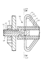
図2〜図4は、前記スクリューコンベヤ式クーラ31の一例を示したもので、図2中36は前記スクリュー30を包囲するように設けられた固定ケーシングであり、該固定ケーシング36は、両端が閉塞された筒状の一方端外側に高温灰入口37をまた他方端外側に低温灰出口38を有しており、且つ内部に給水10の一部を流通させるようにした外部冷却水流路39が形成されている。
【0022】
また、スクリュー30は、前記固定ケーシング36の両端を貫通して軸受40により同芯に回転可能に支持する回転軸41を備えており、該回転軸41には、図3、図4に示すように、周方向に複数配置された内部冷却水流路42が軸長手方向に沿って形成されている。
【0023】
前記回転軸41の外周にはねじ状(螺旋状)の羽根43が取り付けられていると共に、該羽根43には、該羽根43に沿って延設された複数の冷却コイル44,45が一体に取り付けられている。
【0024】
前記回転軸41の一方端46(図2中右端)には、前記内部冷却水流路42と冷却コイル44,45に連通する冷却水導入流路47が形成されている。また、前記回転軸41の他方端48(図2中左端)には、前記内部冷却水流路42に連通する軸側導出流路49と、冷却コイル44,45に連通するコイル側導出流路50とが別々に形成されており、更に前記他方端48の先端には、ロータリージョイント51が備えられて、前記軸側導出流路49に連通する軸側導出管52と、コイル側導出流路50に連通するコイル側導出管53が備えてあり、前記軸側導出管52に流量調節弁54が配置されている。
【0025】
また、前記軸側導出管52及びコイル側導出管53の下流側を合流させて、固定ケーシング36の一方端において外部冷却水流路39に連通するように取り付けられている外部入口55に接続していると共に、固定ケーシング36の他方端には外部出口56を形成している。図中57はモータ29の駆動力を回転軸41に伝えるプーリを示す。
【0026】
次に上記実施の形態の作用を説明する。
【0027】
図1に示す給水ポンプ9からの給水10の一部を、冷却給水供給管32によりスクリューコンベヤ式クーラ31に供給する。一方、モータ29によりスクリュー30の回転を駆動すると、ベッド灰抜出管19から固定ケーシング36内に取入れられたベッド灰6は、スクリュー30の回転により図2の左側から右方向に撹拌されながら搬送され、低温灰出口38から外部の搬出装置24上に排出される。
【0028】
冷却給水供給管32からの給水10は、回転軸41の一方端46に形成された冷却水導入流路47から、回転軸41に形成された内部冷却水流路42と冷却コイル44,45の両方に同時に給水されて該内部冷却水流路42と冷却コイル44,45を流動する間に高温のベッド灰6を冷却した後、回転軸41の他方端48に形成されている内部冷却水流路42に連通した軸側導出流路49と、冷却コイル44,45に連通したコイル側導出流路50とに別々に流入し、更にロータリージョイント51を介して軸側導出管52と、コイル側導出管53とに別々に導出される。
【0029】
この時、軸側導出管52に流量調節弁54を備えているので、該流量調節弁54の開度を調節することにより、前記内部冷却水流路42と冷却コイル44,45に流れる給水10の流量を調節することができ、これにより、ベッド灰6を均一にしかも高能力で冷却することができ、更にスクリュー30自身を高温から保護することができる。
【0030】
また、軸側導出管52及びコイル側導出管53を合流させて、固定ケーシング36の外部冷却水流路39に流通させ、ベッド灰6冷却後の給水10aを外部出口56から導出するようにしているので、冷却コイル44,45によるベッド灰6を撹拌しながらの冷却と、外部冷却水流路39による外部からの冷却とにより、給水10を有効に利用してベッド灰6を効果的に冷却することができる。
【0031】
前記スクリューコンベヤ式クーラ31の外部出口56から導出された給水10aは、戻し管33により脱気器17へ導かれて復水器16からの水と混合されて再び給水ポンプ9に送られる。
【0032】
このとき、前記スクリューコンベヤ式クーラ31からの給水10aの温度が余り上昇しないように(気泡を生じないように)スクリューコンベヤ式クーラ31に供給する給水10の流量を増加させれば、前記昇温後の給水10aを給水ポンプ9の入口に直接戻すこともできるが、図1に示したように昇温後の給水10aを脱気器17に戻すようにすると、給水ポンプ9保護の上で特別の考慮が不要な上、給水10aの温度が上昇して気泡を生じることがあっても問題を生じることがないので運用上有利となる。
【0033】
上記したように、給水10の一部をスクリューコンベヤ式クーラ31に供給してベッド灰6の冷却を行うようにしているので、ベッド灰6の熱を給水10の昇温に有効に利用することができ、且つ従来のようにベッド灰6の冷却のために特別な冷却水を供給する必要がない。
【0034】
また、前記冷却給水供給管32に流量調節弁35を備えているので、該流量調節弁35を調節してスクリューコンベヤ式クーラ31から排出される冷却後のベッド灰6の温度が所定の温度になるように調節することができる。
【0035】
更に、前記スクリューコンベヤ式クーラ31のスクリュー30を駆動するモータ29を、層高調節器34により制御することにより、ベッド灰6の抜出速度を任意に調整して火炉1の流動層7の層高を一定に制御することができる。
【0036】
この時、前記スクリューコンベヤ式クーラ31はスクリュー30による切出し能力を備えているで、スクリューコンベヤ式クーラ31をベッド灰抜出管19の直下に接続配置することができ、流動層ボイラの地上28からの機高を低くすることができる。
【0037】
尚、本発明は上記実施の形態例にのみ限定されるものではなく、節炭器を備えずに給水ポンプからの給水が主ドラムに直接供給される方式、或いは主ドラムの蒸気が蒸気タービン以外の使用場所に供給される方式等の種々の流動層ボイラに適用できること、その他本発明の要旨を逸脱しない範囲内において種々変更を加え得ること、等は勿論である。
【0038】
【発明の効果】
本発明によれば、流動層ボイラの火炉から取り出されるベッド灰を導入すると共に、給水ポンプにより流動層ボイラに供給される給水の一部を冷却給水供給管により導入して、熱交換によりベッド灰の冷却を行うようにしたスクリューコンベヤ式クーラを備え、且つ該スクリューコンベヤ式クーラからの冷却後の給水を給水ポンプの上流側に戻す戻し管を備えた構成としているので、ベッド灰の熱を給水の昇温に有効に利用することができ、且つ従来のようにベッド灰冷却のために特別な冷却水を供給する必要がない。
【0039】
更に、冷却コイルによるベッド灰を撹拌しながらの冷却と、外部冷却水流路による外部からの冷却とにより、給水を有効に利用してベッド灰を効果的に冷却することができ、しかもスクリュー自身を高温から保護できる効果がある。
【0040】
【0041】
【図面の簡単な説明】
【図1】 本発明の実施の形態例を示す系統図である。
【図2】 スクリューコンベヤ式クーラの一例を示す断面図である。
【図3】 図2の回転軸の一部を拡大して示した断面図である。
【図4】 図3のIV−IV矢視図である。
【図5】 従来の流動層ボイラのベッド灰抜出装置の一例を示す系統図である。
【符号の説明】
1 火炉
6 ベッド灰
7 流動層
9 給水ポンプ
10 給水
10a 給水
17 脱気器
30 スクリュー
31 スクリューコンベヤ式クーラ
32 冷却給水供給管
33 戻し管
34 層高調節器
35 流量調節弁
36 固定ケーシング
39 外部冷却水流路
44,45 冷却コイル [0001]
BACKGROUND OF THE INVENTION
The present invention relates to a bed ash extraction device for a fluidized bed boiler that cools high-temperature bed ash discharged from a fluidized bed boiler.
[0002]
[Prior art]
FIG. 5 shows an outline of an example of a conventional fluidized bed boiler.
[0003]
The
[0004]
The fluidized bed boiler is intended to obtain a stable combustion by maintaining the fluidized
[0005]
In order to extract the
[0006]
Since the temperature of the fluidized
[0007]
[Problems to be solved by the invention]
However, in the bed
[0008]
Moreover, in order to control the bed height of the fluidized
[0009]
The present invention has been made in view of such circumstances, and the bed ash extraction of a fluidized bed boiler capable of improving the thermal efficiency of the fluidized bed boiler by effectively using the heat of the bed ash extracted from the fluidized bed boiler. The object is to provide a device.
[0010]
[Means for Solving the Problems]
The bed ash extraction device for a fluidized bed boiler according to the present invention introduces bed ash taken out from the furnace of the fluidized bed boiler and introduces a part of the feed water supplied to the fluidized bed boiler by the feed water pump through the cooling feed water supply pipe. The bed ash of a fluidized bed boiler, comprising: a screw conveyor type cooler that cools the bed ash by heat exchange; and a return pipe that returns the cooled feed water from the screw conveyor type cooler to the upstream side of the feed water pump. The screw conveyor type cooler includes an external cooling water channel provided in a fixed casing, and a cooling coil extending along a blade of a screw inside the fixed casing, the external cooling water channel and the It is characterized by supplying water to the cooling coil to cool the bed ash .
[0011]
[0012]
In the present invention, the bed ash taken out from the furnace of the fluidized bed boiler is introduced, and a part of the feed water supplied to the fluidized bed boiler by the feed water pump is introduced by the cooling feed water supply pipe to cool the bed ash by heat exchange. And a return pipe for returning the water supplied after cooling from the screw conveyor type cooler to the upstream side of the water supply pump. It can be effectively used for temperature, and it is not necessary to supply special cooling water for bed ash cooling as in the prior art.
[0013]
[0014]
[0015]
[0016]
DETAILED DESCRIPTION OF THE INVENTION
Hereinafter, embodiments of the present invention will be described with reference to the drawings.
[0017]
FIG. 1 shows an embodiment of the present invention applied to the fluidized bed boiler of FIG. 5, and the same reference numerals denote the same components in the figure.
[0018]
As shown in FIG. 1, a screw driven by a
[0019]
Further, a cooling
[0020]
Further, a
[0021]
2 to 4 show an example of the screw
[0022]
The
[0023]
A screw-shaped (spiral)
[0024]
A cooling
[0025]
Further, the downstream side of the shaft
[0026]
Next, the operation of the above embodiment will be described.
[0027]
A part of the
[0028]
The
[0029]
At this time, since the flow
[0030]
Further, the shaft-
[0031]
The
[0032]
At this time, if the flow rate of the
[0033]
As described above, since a part of the
[0034]
Further, since the cooling
[0035]
Further, the
[0036]
At this time, since the screw conveyor type cooler 31 has a cutting ability by the
[0037]
The present invention is not limited only to the above embodiment, but a system in which feed water from a feed water pump is directly supplied to a main drum without providing a economizer, or steam in the main drum is other than a steam turbine. Of course, the present invention can be applied to various fluidized bed boilers such as a system supplied to the place of use, and various modifications can be made without departing from the scope of the present invention.
[0038]
【The invention's effect】
According to the present invention, the bed ash taken out from the furnace of the fluidized bed boiler is introduced, and part of the feed water supplied to the fluidized bed boiler by the feed water pump is introduced by the cooling feed water supply pipe, and the bed ash is exchanged by heat exchange. And a return pipe for returning the water supplied after cooling from the screw conveyor type cooler to the upstream side of the water supply pump. Therefore, it is not necessary to supply special cooling water for bed ash cooling as in the prior art.
[0039]
Furthermore, the bed ash can be effectively cooled using the water supply effectively by cooling the bed ash while stirring the bed ash by the cooling coil and cooling from the outside by the external cooling water flow path. There is an effect that can be protected from high temperature.
[0040]
[0041]
[Brief description of the drawings]
FIG. 1 is a system diagram showing an embodiment of the present invention.
FIG. 2 is a cross-sectional view showing an example of a screw conveyor type cooler.
3 is an enlarged cross-sectional view showing a part of a rotating shaft in FIG. 2. FIG.
4 is a view taken along arrow IV-IV in FIG. 3;
FIG. 5 is a system diagram showing an example of a bed ash extraction device of a conventional fluidized bed boiler.
[Explanation of symbols]
DESCRIPTION OF
36 fixed casing
39 External cooling water flow path
44, 45 cooling coil
Claims (1)
Priority Applications (1)
| Application Number | Priority Date | Filing Date | Title |
|---|---|---|---|
| JP28871295A JP3687155B2 (en) | 1995-11-07 | 1995-11-07 | Bed ash extraction device for fluidized bed boiler |
Applications Claiming Priority (1)
| Application Number | Priority Date | Filing Date | Title |
|---|---|---|---|
| JP28871295A JP3687155B2 (en) | 1995-11-07 | 1995-11-07 | Bed ash extraction device for fluidized bed boiler |
Publications (2)
| Publication Number | Publication Date |
|---|---|
| JPH09133318A JPH09133318A (en) | 1997-05-20 |
| JP3687155B2 true JP3687155B2 (en) | 2005-08-24 |
Family
ID=17733718
Family Applications (1)
| Application Number | Title | Priority Date | Filing Date |
|---|---|---|---|
| JP28871295A Expired - Fee Related JP3687155B2 (en) | 1995-11-07 | 1995-11-07 | Bed ash extraction device for fluidized bed boiler |
Country Status (1)
| Country | Link |
|---|---|
| JP (1) | JP3687155B2 (en) |
Cited By (1)
| Publication number | Priority date | Publication date | Assignee | Title |
|---|---|---|---|---|
| US20160045946A1 (en) * | 2014-08-15 | 2016-02-18 | Institute of Nuclear Energy Research, Atomic Energy Council, Executive Yuan, R.O.C. | Waste heat recovery apparatus and method for the same |
Families Citing this family (8)
| Publication number | Priority date | Publication date | Assignee | Title |
|---|---|---|---|---|
| KR100369437B1 (en) * | 2000-08-03 | 2003-01-24 | 한국동서발전(주) | Apparatus for discharging bed media from a fluidized bed combustor |
| KR100416073B1 (en) * | 2000-08-03 | 2004-01-31 | 한국동서발전(주) | Apparatus for cooling bed media for use in a fluidized bed combustor |
| FI122189B (en) * | 2009-12-21 | 2011-09-30 | Foster Wheeler Energia Oy | METHOD AND ARRANGEMENT FOR RECOVERY OF HEAT FROM THE COMBUSTION ASH |
| CN104214754B (en) * | 2014-09-29 | 2016-02-24 | 山东理工大学 | Blue charcoal residual neat recovering system |
| CN104236337B (en) * | 2014-09-29 | 2016-04-06 | 山东理工大学 | Blue charcoal waste heat utilization heat exchanger |
| CN105135424A (en) * | 2015-09-10 | 2015-12-09 | 湖南宜化化工有限责任公司 | Boiler slag dump automation and cooling water treatment device and method |
| CN109899781A (en) * | 2019-01-12 | 2019-06-18 | 湖州加怡新市热电有限公司 | A kind of flying dust back fire device |
| CN116688714B (en) * | 2023-06-07 | 2024-03-22 | 贵州绿色产业技术研究院 | System and method for continuous capture of solid amine carbon |
-
1995
- 1995-11-07 JP JP28871295A patent/JP3687155B2/en not_active Expired - Fee Related
Cited By (2)
| Publication number | Priority date | Publication date | Assignee | Title |
|---|---|---|---|---|
| US20160045946A1 (en) * | 2014-08-15 | 2016-02-18 | Institute of Nuclear Energy Research, Atomic Energy Council, Executive Yuan, R.O.C. | Waste heat recovery apparatus and method for the same |
| US9891010B2 (en) * | 2014-08-15 | 2018-02-13 | Institute of Nuclear Energy Research, Atomic Energy Council, Executive Yuan, R.O.C. | Waste heat recovery apparatus having hollow screw shaft and method for the same |
Also Published As
| Publication number | Publication date |
|---|---|
| JPH09133318A (en) | 1997-05-20 |
Similar Documents
| Publication | Publication Date | Title |
|---|---|---|
| FI91437C (en) | Method of operation of a gas turbine unit | |
| JP4411216B2 (en) | Thermal power machine | |
| EP0684369B1 (en) | Steam cooling of gas turbine with backup air cooling | |
| JP4288169B2 (en) | Temperature adjustment method for screw vacuum pump | |
| JP3687155B2 (en) | Bed ash extraction device for fluidized bed boiler | |
| KR100322163B1 (en) | Apparatus for cooling the coolant of the gas turbine of the gas-steam turbine apparatus | |
| US20040261417A1 (en) | Steam turbine, steam turbine plant and method of operating a steam turbine in a steam turbine plant | |
| CN101184912B (en) | Gas turbine engine cooling system and method | |
| JPH0626400A (en) | Dual pressure turbine | |
| JPS6118649B2 (en) | ||
| JPH08240105A (en) | Combined cycle power plant and steam turbine warming method | |
| JPS5827803A (en) | Gas turbine | |
| CN107448323A (en) | The fluid of gas turbine heating is used for the purposes of reducing agent evaporation | |
| US6702547B2 (en) | Gas turbine | |
| JPH07115581B2 (en) | Vehicle heating system | |
| JPH08166116A (en) | Screw conveyor type ash cooler | |
| JP2003161164A (en) | Combined-cycle power generation plant | |
| JP4611969B2 (en) | Air cooler for power plant and use of this air cooler | |
| RU2298681C2 (en) | Turbine device and method of its operation | |
| US2316522A (en) | Rotary vapor generator | |
| US4365953A (en) | Cooler for combustible material | |
| CN103089331A (en) | Method for controlling gas turbine rotor temperature during periods of extended downtime | |
| JP2008096087A (en) | Steam boiler device | |
| JPH0646140B2 (en) | Sintered exhaust heat recovery device | |
| JPH01237325A (en) | Power plant |
Legal Events
| Date | Code | Title | Description |
|---|---|---|---|
| A977 | Report on retrieval |
Free format text: JAPANESE INTERMEDIATE CODE: A971007 Effective date: 20041022 |
|
| A131 | Notification of reasons for refusal |
Free format text: JAPANESE INTERMEDIATE CODE: A131 Effective date: 20041102 |
|
| A521 | Written amendment |
Free format text: JAPANESE INTERMEDIATE CODE: A523 Effective date: 20041220 |
|
| TRDD | Decision of grant or rejection written | ||
| A01 | Written decision to grant a patent or to grant a registration (utility model) |
Free format text: JAPANESE INTERMEDIATE CODE: A01 Effective date: 20050517 |
|
| A61 | First payment of annual fees (during grant procedure) |
Free format text: JAPANESE INTERMEDIATE CODE: A61 Effective date: 20050530 |
|
| FPAY | Renewal fee payment (event date is renewal date of database) |
Free format text: PAYMENT UNTIL: 20080617 Year of fee payment: 3 |
|
| S531 | Written request for registration of change of domicile |
Free format text: JAPANESE INTERMEDIATE CODE: R313531 |
|
| S533 | Written request for registration of change of name |
Free format text: JAPANESE INTERMEDIATE CODE: R313533 |
|
| FPAY | Renewal fee payment (event date is renewal date of database) |
Free format text: PAYMENT UNTIL: 20080617 Year of fee payment: 3 |
|
| R350 | Written notification of registration of transfer |
Free format text: JAPANESE INTERMEDIATE CODE: R350 |
|
| FPAY | Renewal fee payment (event date is renewal date of database) |
Free format text: PAYMENT UNTIL: 20090617 Year of fee payment: 4 |
|
| FPAY | Renewal fee payment (event date is renewal date of database) |
Free format text: PAYMENT UNTIL: 20100617 Year of fee payment: 5 |
|
| FPAY | Renewal fee payment (event date is renewal date of database) |
Free format text: PAYMENT UNTIL: 20110617 Year of fee payment: 6 |
|
| FPAY | Renewal fee payment (event date is renewal date of database) |
Free format text: PAYMENT UNTIL: 20110617 Year of fee payment: 6 |
|
| FPAY | Renewal fee payment (event date is renewal date of database) |
Free format text: PAYMENT UNTIL: 20120617 Year of fee payment: 7 |
|
| FPAY | Renewal fee payment (event date is renewal date of database) |
Free format text: PAYMENT UNTIL: 20120617 Year of fee payment: 7 |
|
| FPAY | Renewal fee payment (event date is renewal date of database) |
Free format text: PAYMENT UNTIL: 20130617 Year of fee payment: 8 |
|
| FPAY | Renewal fee payment (event date is renewal date of database) |
Free format text: PAYMENT UNTIL: 20140617 Year of fee payment: 9 |
|
| LAPS | Cancellation because of no payment of annual fees |