JP3686552B2 - Construction machine console box - Google Patents
Construction machine console box Download PDFInfo
- Publication number
- JP3686552B2 JP3686552B2 JP17650999A JP17650999A JP3686552B2 JP 3686552 B2 JP3686552 B2 JP 3686552B2 JP 17650999 A JP17650999 A JP 17650999A JP 17650999 A JP17650999 A JP 17650999A JP 3686552 B2 JP3686552 B2 JP 3686552B2
- Authority
- JP
- Japan
- Prior art keywords
- frame
- locking member
- locking
- shaft
- end portion
- Prior art date
- Legal status (The legal status is an assumption and is not a legal conclusion. Google has not performed a legal analysis and makes no representation as to the accuracy of the status listed.)
- Expired - Fee Related
Links
- 238000010276 construction Methods 0.000 title claims description 7
- 230000001105 regulatory effect Effects 0.000 claims 1
- 230000000694 effects Effects 0.000 description 4
- 238000010586 diagram Methods 0.000 description 2
- 238000005452 bending Methods 0.000 description 1
- 230000006835 compression Effects 0.000 description 1
- 238000007906 compression Methods 0.000 description 1
Images


Classifications
-
- E—FIXED CONSTRUCTIONS
- E02—HYDRAULIC ENGINEERING; FOUNDATIONS; SOIL SHIFTING
- E02F—DREDGING; SOIL-SHIFTING
- E02F9/00—Component parts of dredgers or soil-shifting machines, not restricted to one of the kinds covered by groups E02F3/00 - E02F7/00
- E02F9/20—Drives; Control devices
- E02F9/2004—Control mechanisms, e.g. control levers
Landscapes
- Engineering & Computer Science (AREA)
- Mining & Mineral Resources (AREA)
- Civil Engineering (AREA)
- General Engineering & Computer Science (AREA)
- Structural Engineering (AREA)
- Operation Control Of Excavators (AREA)
- Vehicle Step Arrangements And Article Storage (AREA)
Description
【0001】
【発明の属する技術分野】
この発明は、パワーショベル等の建設機械の運転席の側方に設けられるコンソールボックスに関する。
【0002】
【従来の技術】
一般に、この種のコンソールボックスは、運転席に固定された固定フレームと、この固定フレームに使用位置と跳ね上げ位置との間を上下方向へ回動可能に支持された回動フレームとを備えており、固定フレームと回動フレームとの間には、回動フレームを使用位置側から跳ね上げ位置側へ向って上方に付勢する付勢手段が設けられている。そして、作業機械の運転時には回動フレームが使用位置に回動されており、運転席に腰掛けた運転者は回動フレームに設けられた操作レバーを操作する。一方、運転者が作業機械から乗降する際には、回動フレームが跳ね上げ位置に回動され、運転者の乗降を可能にする。
【0003】
また、固定フレームと回動フレームとの間には、回動フレームを付勢手段の付勢力に抗して使用位置に位置させておくための係止機構が設けられている。図7は、特開平10−140614号公報に記載されたコンソールボックスの係止機構を示すものであり、回動フレーム(図示せず)が第1回動軸O1を中心として回動可能に支持されている。回動フレームの前端部には、係止部材1が第2回動軸O2を中心として回動可能に支持されている。係止部材1には、ガイド孔(ガイド部)1aが形成されており、このガイド孔1aには、固定フレーム(図示せず)に設けられた係止軸部2がガイド孔1aの長手方向へ相対移動可能に挿入されている。そして、回動フレームが矢印A方向へ回動して係止軸部2がガイド孔1aの上端部に突き当たると、回動フレームが使用位置に位置する。逆に、回動フレームが矢印B方向へ回動して係止軸2がガイド孔1aの下端部に突き当たると、回動フレームが跳ね上げ位置に位置するようになっている。
【0004】
ガイド孔1aの上下の端部には、上横孔1bおよび下横孔1cがそれぞれ形成されている。そして、回動フレームを使用位置に位置させた状態で係止部材1を第2回動軸O2を中心として矢印C方向へ回動させると、固定フレームに設けられた係止軸部2が上横孔1bに入り込んで係合する。この結果、回動フレームが係止部材1を介して固定フレームに位置固定される。回動フレームを跳ね上げ位置に回動させた状態で係合部材1を矢印D方向へ回動させると、係止軸部2が下横孔1cに入り込んで係合する。これにより、回動フレームが跳ね上げ位置に位置固定される。
【0005】
ところで、係止軸部2が上横孔1bに係合した状態においては、付勢手段の付勢力が第2回動軸O2を介して係止部材1に作用し、係止部材1に作用する付勢力を係止軸部2が受ける。ここで、仮にガイド孔1aを第1回動軸O1に近接させ、それに伴って上横孔1bを第1回動軸O1近傍に形成したものとすると、付勢手段の付勢力が作用する第2回動軸O2と付勢力を受ける係止軸部2との間の距離が長くなる結果、それらの間の係止部材2に付勢手段の付勢力が大きな曲げ力として作用する。このため、係止部材1が変形するおそれがある。そこで、上横孔1bおよびガイド孔1aは、第2回動軸O2の近傍に設けられている。
なお、係止軸部2が下横孔1cに係合した状態においては、係止部材1に作用する付勢力が弱いので問題になることはない。
【0006】
また、ガイド孔1aは、第1回動軸O1を中心とし、第1回動軸O1と係止軸部2との間の距離を半径とする円弧にほぼ沿って形成されている。これは、仮にガイド孔1aを円弧以外の形状にすると、回動フレームの回動に伴って係止軸部2が第2回動軸O2を中心として回動させられる。その結果、係止部材1を操作するためのレバー3が第2回動軸O2を中心として回動させられる。その結果、レバー3によって運転者が怪我をする危険性がある。このような危険性を未然に回避するために、ガイド孔1aを円弧状に形成したものである。
【0007】
【発明が解決しようとする課題】
上記のように、ガイド孔1aを第2回動軸O2近傍に配置し、かつ円弧状に形成すると、ガイド孔1aの長さが跳ね上げ角度と、第1回動軸O1からガイド孔1aまでの距離とに比例するため、図7からも明らかなように、ガイド孔1aの長さが長くなり、それに対応して係止部材1が斜め下方に向かって長くなる。その結果、係止部材1の下端部が下方に位置する。特に、係止軸部2がガイド孔1aの上端部に突き当たったときには、係止部材1の下端部がより一層下方に位置するようになる。このため、従来のコンソールボックスを備えた作業機械においては、係止部材1が運転席の床面に突き当たらないようにするために、床面を低くしなければならず、その分だけ設計の自由度が制限されるという問題があった。
【0008】
【課題を解決するための手段】
この発明は、上記の問題を解決するために、固定フレームと、この固定フレームに水平な第1回動軸を中心として上下方向へ回動可能に支持され、使用位置とこの使用位置から上方へ所定角度だけ離れた跳ね上げ位置との間を回動可能である回動フレームと、この回動フレームを上記使用位置側から上記跳ね上げ位置側に向かって付勢する付勢手段と、上記第1回動軸より前方に配置された水平な第2回動軸を中心として前端部が上記回動フレームに上下方向へ回動可能に支持された係止部材とを備え、上記固定フレームには係止軸部が設けられ、上記係止部材には、上記係止軸部が長手方向へ相対移動可能に挿入され、一端部が上記係止軸部に突き当たることによって上記回動フレームの使用位置を規制し、他端部が上記係止軸部に突き当たることによって上記回動フレームの跳ね上げ位置を規制するガイド部が設けられ、このガイド部が、上記第1回動軸を中心とし、かつ上記第1回動軸と上記係止軸部との間の距離を半径とする円弧状に形成された建設機械のコンソールボックスにおいて、上記ガイド部を上記係止部材の上記第1回動軸に近接した後端部に配置し、上記係止部材と上記固定フレームとには、上記回動フレームを上記使用位置に回動させた状態で上記係止部材を上記第2回動軸を中心として一方向へ回動させたときに互いに係合することにより、上記回動フレームの使用位置から跳ね上げ位置側への回動を阻止する一対の係合部を設け、この一対の係合部を、上記ガイド部より前方に位置するよう、上記係止部材の前端部とその近傍の上記固定フレームとに配置したことを特徴としている。
この場合、上記係止部材の前端部には、上記第2回動軸より前方へ向かって延びるロックレバーの後端部を固定し、上記一対の係合部については、上記ロックレバーをその前端部が下方へ向かうように回動させると互いに係合するよう、上記第2回動軸の下側に配置するのが望ましい。
また、
また、上記一対の係合部が互いに係合する方向へ上記係止部材を回動付勢する第2付勢手段をさらに備えていることが望ましい。
さらに、上記第2付勢手段は上記回動フレームと上記係止部材との間に設けるのが望ましい。
【0009】
【発明の実施の形態】
以下、この発明の一実施の形態について図1〜図6を参照して説明する。
図3は、この発明に係るコンソールボックスAを備えたミニショベル100を示すものであり、ミニショベル100はクローラ101で走行するようになっている。
【0010】
ミニショベル100の車体102の前部にはブレード103が設けられ、車体102の上には、水平方向に旋回する旋回台104が設けられている。旋回台104の前部には、作業機械取付部105が設けられており、この作業機械取付部105にはブーム106の基端部が水平方向および上下方向へ回動可能に取り付けられている。ブーム106の先端部には、アーム107の基端部が上下方向へ回動可能に取り付けられ、アーム107の先端部には、バケット108が上下方向へ回動可能に取り付けられている。また、旋回台104の上には、運転者が座る運転席109が設けられている。
【0011】
図4は運転席109の正面図であり、図4において符号110は、運転席109のシートである。このシート110は、シートクッション111とシートバック112とを備えており、シートクッション111はシートフレーム(固定フレーム)113に固定されている。シートフレーム113は、旋回台104の上面、つまり運転席109の床面114に前後方向移動機構115を介して設けられている。したがって、シート110は、前後方向へ位置調節可能である。
【0012】
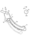
シートフレーム113の左右の両側部には、コンソールボックス10がそれぞれ設けられている。一方のコンソールボックス10(図4において右側のコンソールボックス10)は、左右方向に延びる水平な第1回動軸O1を中心として回動可能である。この場合、コンソールボックス10は、図5に示す使用位置と、この使用位置から前端部が上方へ所定角度(例えば、30〜40°程度)だけ離れた跳ね上げ位置との間を回動可能である。勿論、運転者が運転席109に座っているときには使用位置に回動され、運転席109から乗降する際には跳ね上げ位置に回動される。なお、他方のコンソールボックス10は、図4の左側から運転者の乗降が行われないので回動可能になっていないが、第1回動軸O1を中心として回動可能にしてもよい。
【0013】
各コンソールボックス10の前側の上部には、操作レバー11がそれぞれ立設されており、各操作レバー11によってブーム106、アーム107およびバケット108等を操作するようになっている。なお、符号12は、操作レバー11とコンソールボックス10との間の隙間を覆うブーツであり、ゴム等の柔軟な材質で形成されている。
【0014】
図4において右側のコンソールボックス10は、次の構成により、使用位置と跳ね上げ位置との間を回動することができ、しかも使用位置と跳ね上げ位置とにおいてシートフレーム113に回動不能に係止することができるようになっている。
【0015】
すなわち、図5および図6に示すように、シートフレーム113の後端面には、右側のコンソールボックス10側へ向って突出する支持腕115が固定されており、この支持腕115には、軸116がその軸線を第1回動軸O1と一致させて設けられている。この軸116を介して回動フレーム13の後端部がシートフレーム113に上下方向へ回動可能に支持されている。回動フレーム13は、使用位置と跳ね上げ位置との間を回動可能であり、使用位置においてはほぼ水平になっている。これから明らかなように、この実施の形態ではシートフレーム113が固定フレームとして兼用されているが、固定フレームを別途用意し、この固定フレームをシートフレームに固定するようにしてもよい。
【0016】
回動フレーム13の前端部上側には、上記操作レバー11が取り付けられている。操作レバー11の取付態様は、従来のものと同様であるので、その説明は省略する。また、回動フレーム13の前後の端部に設けられた取付部13a,13bにはコンソールボックス10のカバー14が固定されている。このカバー14と操作レバー11との間に上記ブーツ12が設けられている。
【0017】
図6に示すように、シートフレーム113と回動フレーム13との互いに対向する側部間には、ダンパ(付勢手段)15が設けられている。このダンパ15によって回動フレーム13が使用位置側から跳ね上げ位置側に向って付勢されている。ダンパ15に代えて、他の付勢手段、例えば引っ張りばね、あるいは圧縮ばねを用いてもよい。
【0018】
第1回動軸O1の前方で、回動フレーム13の前後方向のほぼ中央部には、軸線(第2回動軸)O2を左右方向に向けた水平な軸16が回動自在に設けられている。この軸16のシートフレーム113側に突出した一端部には、前後方向に延びる係止部材17の前端部が連結固定されている。軸16の他端部には、ロックレバー18の後端部が連結固定されている。図4に示すように、ロックレバー18の前端部はカバー14から前方に突出しており、運転席109に座った運転者は、ロックレバー18の前端部を握って回動操作することができ、それによって係止部材17を上下方向へ回動操作することができるようになっている。
【0019】
図1、図2および図5に示すように、係止部材17の後端部で第1回動軸O1の近傍下側には、ガイド孔(ガイド部)17aが形成されている。一方、係止部材17と対向するシートフレーム113の側面の後端部には、係止軸部19が水平方向へ突出形成されている。この係止軸部19は、ガイド孔17aにローラ20を介して移動可能に嵌め込まれている。したがって、回動フレーム13が第1回動軸O1を中心として回動し、それに伴って係止部材17が第1回動軸O1を中心として回動すると、係止軸部19がガイド孔17a内を相対移動する。このとき、ガイド溝17aが、第1回動軸O1を中心とし、かつ第1回動軸O1と係止軸部19との間の距離を半径する円弧にほぼ沿うように形成されている。したがって、回動フレーム13が回動するときに、係止部材17およびロックレバー18が第2回動軸O2を中心として回動することはほとんどない。また、ガイド孔17aは、その前側の端部に係止軸部19が突き当たったとき、回動フレーム13が使用位置に位置し、後側の端部に係止軸部19が突き当たったとき、回動フレーム13が跳ね上げ位置に位置するようにその長さが設定されている。
【0020】
ガイド孔17aの前側の端部には、ガイド孔17aから下方へ向って延びる逃げ孔17bが形成され、後側の端部には、ガイド孔17aから上方へ向って延びる係止孔17cが形成されている。逃げ孔17bおよび係止孔17cの幅は、ローラ20を介して係止軸部19が入り込むことができるように設定されている。しかも、各逃げ孔17bおよび係止孔17cは、第2回動軸O2を中心とする円弧状に形成されている。したがって、回動フレーム13を使用位置に位置させた状態で、係止部材17をその後端部が下方へ向うように回動させると、係止軸部19が逃げ孔17bに入り込んで係合する。一方、回動フレーム13を跳ね上げ位置に位置させた状態で、係止部材17をその後端部が上方へ向うように回動させると、係止軸部19が係合孔17cに入り込んで係合する。
【0021】
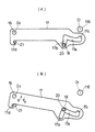
係止部材17の下面の前端部で第2回動軸O2のほぼ真下に位置する箇所には、係合溝17dが形成されている。この係合溝17dは、第1回動軸O1側を向く端部が開口している。一方、係合部材17と対向するシートフレーム113の側面には、係合軸21が係止部材17側へ向かって水平に突出形成されている。この係合軸21は、図1(B)に示すように、回動フレーム13が使用位置に回動した状態においては、係合溝17dから抜け出てその開口部と対向している。その状態から係止部材17をその後端部が上方へ向かうように矢印X方向へ回動させると、図1(A)に示すように、係合溝17dに入り込んで係合するように配置されている。係合軸21が係合溝17dに係合すると、係止部材17が第1回動軸O1を中心として回動することができなくなり、その結果回動フレーム13がシートフレーム113に係止部材17を介して使用位置に係止される。これから明らかなように、係合溝17dと係合軸21とによって一対の係合部が構成されている。なお、係合軸21が係合溝17dの端部に突き当たったとき、係止軸部19は逃げ孔17bの下端部から若干離れている。
【0022】
図6に示すように、上記回動フレーム13と係止部材17との対向する側面間には、ばね(第2の付勢手段)22が設けられている。このばね22の一端部は、連結軸23を介して回動フレーム13に連結され、ばね22の他端部は、連結軸24を介して係止部材17に連結されている。したがって、ばね22は係止部材17を第2回動軸O2を中心として回動付勢する。ばね22の付勢方向は、連結軸23,24の位置を適宜調節することにより、係止部材17の回動位置に応じて切り替わるようになっている。すなわち、係止軸部19がガイド孔17aの端部に突き当たった位置からガイド孔17aを通り、逃げ孔17bに若干入り込んだ位置(この位置では、係合軸21が係合溝17dに僅かに入り込んでいる。以下、この位置を切換位置という。)までの回動範囲では、係止部材17をその後端部が下方へ向うように回動付勢する。その一方、係止軸部19が切換位置から逃げ孔17bのさらに下端側へ入り込んだ回動範囲では、係止部材17をその後端部が上方へ向うように回動付勢する。
【0023】
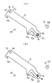
したがって、回動フレーム13を使用位置に回動させた図1(B)に示す状態において、係止部材17を矢印X方向へ切換位置を越えるまで回動させると、その後は係止部材17がばね22の付勢力によって同方向へ回動させられる。そして、図1(A)に示すように、係合軸21が係合溝17dの端部に突き当てられるとともに、その状態に維持される。一方、図2(A)、(B)に示すように、回動フレーム13を跳ね上げ位置に回動させると、係止部材17がばね22の付勢力により矢印Y方向へ回動させられる。そして、係止軸部19が係止孔17cに入り込んでその端部に突き当たるとともに、その状態に維持される。したがって、ミニショベル100の運転中の振動により、係合軸21が係合溝17dから外れたり、係止軸部19が係止孔17cから外れることがなく、回動フレーム13は、使用位置または跳ね上げ位置に維持される。
【0024】
なお、図示していないが、シートフレーム113には、ミニショベル100の電気系統をON、OFFするための補助スイッチが設けられている。この補助スイッチは、係合軸21が係合溝17dの端部に突き当たる直前にまで係止部材17を回動させると、係止部材17によりOFF状態からON状態に切り換えられ、係合軸21が係合溝17dの端部に突き当たった状態から若干離れるまで係止部材17を回動させると、ON状態からOFF状態に切り替わるようになっている。これにより、運転者が乗降する際にミニショベル100が不意に動作するような事態を確実に防止している。
【0025】
上記構成のコンソールボックスにおいて、いま回動フレーム13が使用位置に位置し、係合軸21が係合溝17dに係合しているものとする。この状態からコンソールボックス10を跳ね上げ位置に回動させるには、まずロックレバー18を上方へ回動させ、係止軸部19が逃げ孔17bの上端部に突き当たるまで、係止部材17を図1(B)の矢印Y方向へ回動させる。これにより、係合溝17dと係合軸21との係合を解除させる。すると、回動フレーム13がダンパ15の付勢力によって跳ね上げ位置側へ向かって上方へ回動する。このとき、係合溝17dと係合軸21との係合を解除させるためのロックレバー18の操作方向が、回動フレーム13(コンソールボックス10)の回動方向と同一であるから、ロックレバー18を違和感なく操作することができる。
【0026】
図2(A)に示すように、回動フレーム13が跳ね上げ位置まで回動すると、係止軸部19がガイド孔17aの後端部に突き当たり、回動フレーム13が停止する。その後、係止部材17がばね22の付勢力により図2(B)の矢印X方向へ回動させられ、係止軸部19が係止孔17cの端部に突き当たるまで入り込んで係合する。これにより、回動フレーム13が跳ね上げ位置に係止される。
【0027】
跳ね上げ位置に係止された回動フレーム13を使用位置に回動させる場合には、まずロックレバー18を下方へ回動させ、係止軸部19が係止孔17cから抜け出てガイド孔17aに入り込むまで係止部材17を図2の矢印Y方向へ回動させる。その後、回動フレーム13を使用位置側へ向って下方に回動させる。このとき、係止孔17cと係止軸部19との係合を解除させるためのロックレバー18の回動方向が、回動フレーム13の回動方向と同一であるから、ロックレバー18をそのまま下方へ回動させることにより、回動フレーム13を使用位置側へ回動させることができる。図1(B)に示すように、回動フレーム13が使用位置に達すると、係止軸部19がガイド孔17aの前端部に突き当たり、回動フレーム13が停止する。その後、ロックレバー18をさらに下方へ回動させると、図1(A)に示すように、係合軸21が係合溝17dに係合する。これにより、回動フレーム13が使用位置に係止される。
【0028】
上記のように、このコンソールボックス10においては、ガイド孔17aを係止部材17の後端部に形成しているので、係止部材17の前端部に形成した場合に比して、一定の跳ね上げ角度に対するガイド孔17aの長さを短くすることができる。特に、この実施の形態のように、ガイド孔17aを第1回動軸O1の下側に形成した場合には、図1(A)、(B)に示すように、回動フレーム13を使用位置に位置させたときガイド溝17aがほぼ水平になる。したがって、係止部材17の上下方向の長さを短くすることができる。よって、運転席109の床面114を低くする必要がなく、その分だけ設計の自由度を広くすることができる。しかも、回動フレーム13が使用位置に位置しているときには、ダンパ15の付勢力を係合溝17dに係合した係合軸21が受けるが、係合溝17dおよび係合軸21が係止部材17の前端部側に配置され、ダンパ15の付勢力が作用する第2回動軸O2に近接しているから、第2回動軸O2と係合軸21との間の係止部材17には、大きな力が作用することがない。したがって、係止部材17が変形するおそれもない。なお、係合溝17dの端部に係合軸21が突き当たった状態のとき、係止軸部19が逃げ孔17bの端部から離れているので、それらに付勢力が作用することはない。
【0029】
なお、この発明は、上記の実施の形態に限定されるものでなく、適宜変更可能である。
例えば、上記の実施の形態においては、固定フレームたるシートフレーム113に係合軸21を形成し、係止部材17に係合溝17dを形成しているが、シートフレーム113に係合溝を形成し、係止部材17に係合軸を形成してもよい。また、上記の実施の形態においては、係合溝17dを第2回動軸O2の下側に配置しているが、第2回動軸O2の上側に配置してもよい。その場合には、係合溝17dの第1回動軸O1と逆側を向く端部を開口させ、その前方に係合軸21を配置すればよい。そのようにすれば、上記の実施の形態と同様に、係止軸部19と係止孔17cとの係合を解除させるためのロックレバー18の回動方向を回動フレーム13の使用位置側への回動方向と同一にすることができるとともに、係合溝17dと係合軸21との係合を解除させるためのロックレバー18の回動方向を回動フレーム13の跳ね上げ位置側への回動方向と同一にすることができるからである。
【0030】
【発明の効果】
以上説明したように、この発明によれば、係止部材の上下方向の長さを短くすることができる。したがって、作業機械の運転席の床面を低くする必要がなく、その分だけ設計の自由度の幅を広くすることができる。しかも、付勢手段の不正力によって係止部材が変形させられるのを防止することができるという効果が得られる。
また、係止部材の前端部にロックレバーを設けるとともに、このロックレバーを上方へ回動させたときに一対の係合部が互いに係合するように各係合部を配置すれば、回動フレーム(コンソールボックス)の係止状態を解除するためのロックレバーの回動方向を、回動フレームの意図する回動方向と一致させることができるという効果が得られる。
さらに、一対の係合部が互いに係合する方向へ係止部材を付勢する第2付勢手段を設ければ、コンソールボックスを使用位置に確実に係止させることができるという効果が得られる。
【図面の簡単な説明】
【図1】この発明の一実施の形態の係止部材と係止軸部および係合軸との関係を示す図であって、図1(A)はコンソールボックスを使用位置に係止したときの関係を示し、図1(B)はコンソールボックスの係止を解除したときの関係を示している。
【図2】図1と同様の図であって、図2(A)はコンソールボックスを跳ね上げ位置に回動させたときの関係を示し、図2(B)はコンソールボックスを跳ね上げ位置で係止したときの関係を示している。
【図3】この発明に係るコンソールボックスを備えた作業機械の一例を示す斜視図である。
【図4】同作業機械の運転席の正面図である。
【図5】同作業機械のコンソールボックスの要部を示す側面図である。
【図6】同コンソールボックスの平面図である。
【図7】従来のコンソールボックスを使用位置に回動させたときにおける係止部材と係止軸部との関係を示す図である。
【符号の説明】
O1 第1回動軸
O2 第2回動軸
10 コンソールボックス
13 回動フレーム
15 ダンパ(付勢手段)
17 係止部材
17a ガイド孔(ガイド部)
17b 逃げ孔
17d 係合溝(係合部)
18 ロックレバー
19 係止軸部
21 係合軸(係合部)
22 ばね(第2付勢手段)[0001]
BACKGROUND OF THE INVENTION
The present invention relates to a console box provided on the side of a driver's seat of a construction machine such as a power shovel.
[0002]
[Prior art]
In general, this type of console box includes a fixed frame fixed to a driver's seat and a rotating frame supported by the fixed frame so as to be rotatable in the vertical direction between a use position and a flip-up position. In addition, an urging means for urging the rotating frame upward from the use position side to the flip-up position side is provided between the fixed frame and the rotating frame. When the work machine is operated, the rotating frame is rotated to the use position, and the driver sitting on the driver's seat operates an operation lever provided on the rotating frame. On the other hand, when the driver gets on and off the work machine, the turning frame is turned to the flip-up position, and the driver can get on and off.
[0003]
In addition, a locking mechanism is provided between the fixed frame and the rotating frame for positioning the rotating frame at the use position against the urging force of the urging means. FIG. 7 shows a locking mechanism for a console box described in Japanese Patent Laid-Open No. 10-140614 , and a rotating frame (not shown) can be rotated about a first rotation axis O1. It is supported. The locking member 1 is supported at the front end of the rotation frame so as to be rotatable about the second rotation axis O2. A guide hole (guide portion) 1a is formed in the locking member 1, and a locking shaft portion 2 provided on a fixed frame (not shown) is provided in the
[0004]
An upper horizontal hole 1b and a lower
[0005]
Incidentally, in the state where the locking shaft portion 2 is engaged with the upper lateral hole 1b, it acts on the locking member 1 the biasing force of the biasing means through a second rotation axis O 2, the locking member 1 The locking shaft portion 2 receives the urging force that acts. Here, if the
In the state where the locking shaft portion 2 is engaged with the lower
[0006]
The
[0007]
[Problems to be solved by the invention]
As described above, to place the
[0008]
[Means for Solving the Problems]
In order to solve the above-described problem, the present invention is supported by a fixed frame and a fixed pivot frame so as to be pivotable in the vertical direction about a horizontal first pivot shaft. A rotating frame capable of rotating between the flip-up positions separated by a predetermined angle; biasing means for biasing the rotating frame from the use position side toward the flip-up position side; A locking member having a front end portion supported by the rotating frame so as to be capable of rotating in the vertical direction around a horizontal second rotating shaft disposed in front of the first rotating shaft; A locking shaft portion is provided, and the locking member is inserted into the locking member so as to be relatively movable in the longitudinal direction, and one end portion of the locking member abuts against the locking shaft portion, so that the rotating frame is used. The other end abuts against the locking shaft. Thus, a guide portion for restricting the flip-up position of the rotating frame is provided. The guide portion is centered on the first rotating shaft, and is formed between the first rotating shaft and the locking shaft portion. in the console box distance for a construction machine is formed in a circular arc shape whose radius between, the guide portion is disposed at a rear end portion close to the first rotation shaft of the locking member, the locking member the upper SL fixed frame, with each other when the locking member is rotated in one direction about said second rotation axis in a state where the rotating frame is rotated to the use position engages the By providing a pair of engaging portions that prevent the rotating frame from rotating from the use position to the flip-up position side, the pair of engaging portions are positioned forward of the guide portion. Arranged on the front end of the locking member and the fixed frame near it It is characterized in that the.
In this case, the rear end portion of the lock lever extending forward from the second rotation shaft is fixed to the front end portion of the locking member, and the lock lever is connected to the front end of the pair of engaging portions. It is desirable to dispose the second rotating shaft below the second rotating shaft so as to engage with each other when the portions are rotated downward .
Also,
Moreover, it is desirable to further include second urging means for urging the locking member in a direction in which the pair of engaging portions engage with each other.
Further, it is desirable that the second urging means is provided between the rotating frame and the locking member.
[0009]
DETAILED DESCRIPTION OF THE INVENTION
An embodiment of the present invention will be described below with reference to FIGS.
FIG. 3 shows a
[0010]
A
[0011]
FIG. 4 is a front view of the driver's
[0012]
[0013]
An
[0014]
In FIG. 4, the
[0015]
That is, as shown in FIGS. 5 and 6, a
[0016]
The
[0017]
As shown in FIG. 6, a damper (biasing means) 15 is provided between the side portions of the
[0018]
In front of the first rotation axis O 1 , a
[0019]
As shown in FIGS. 1, 2, and 5, a guide hole (guide portion) 17 a is formed at the rear end portion of the locking
[0020]
A
[0021]
The portion located beneath substantially the lower surface of the second turning axis at the front end O 2 of the locking
[0022]
As shown in FIG. 6, a spring (second urging means) 22 is provided between the opposing side surfaces of the
[0023]
Accordingly, in the state shown in FIG. 1B in which the
[0024]
Although not shown, the
[0025]
In the console box configured as described above, it is assumed that the
[0026]
As shown in FIG. 2 (A), when rotated to the position flip-up is the pivoting
[0027]
When the
[0028]
As described above, in the
[0029]
In addition, this invention is not limited to said embodiment, It can change suitably.
For example, in the above embodiment, the
[0030]
【The invention's effect】
As described above, according to the present invention, the vertical length of the locking member can be shortened. Therefore, it is not necessary to lower the floor surface of the driver's seat of the work machine, and the range of design freedom can be widened accordingly. And the effect that it can prevent that a locking member is deform | transformed by the improper force of an urging | biasing means is acquired.
In addition, a lock lever is provided at the front end of the locking member, and if each engagement portion is arranged so that the pair of engagement portions engage with each other when the lock lever is rotated upward, There is an effect that the rotation direction of the lock lever for releasing the locked state of the frame (console box) can be matched with the intended rotation direction of the rotation frame.
Furthermore, if the second urging means for urging the locking member in a direction in which the pair of engaging portions engage with each other is provided, an effect that the console box can be reliably locked at the use position can be obtained. .
[Brief description of the drawings]
FIG. 1 is a diagram showing a relationship between a locking member, a locking shaft portion, and an engaging shaft according to an embodiment of the present invention, and FIG. 1 (A) shows a state in which a console box is locked at a use position. FIG. 1B shows the relationship when the console box is unlocked.
2 is a view similar to FIG. 1, in which FIG. 2 (A) shows the relationship when the console box is rotated to the flip-up position, and FIG. 2 (B) is the console box in the flip-up position. The relationship when locked is shown.
FIG. 3 is a perspective view showing an example of a work machine including a console box according to the present invention.
FIG. 4 is a front view of a driver's seat of the working machine.
FIG. 5 is a side view showing the main part of the console box of the working machine.
FIG. 6 is a plan view of the console box.
FIG. 7 is a diagram illustrating a relationship between a locking member and a locking shaft when a conventional console box is rotated to a use position.
[Explanation of symbols]
O 1 First rotating shaft O 2
17
18
22 Spring (second biasing means)
Claims (3)
上記ガイド部を上記係止部材の上記第1回動軸に近接した後端部に配置し、上記係止部材と上記固定フレームとには、上記回動フレームを上記使用位置に回動させた状態で上記係止部材を上記第2回動軸を中心として一方向へ回動させたときに互いに係合することにより、上記回動フレームの使用位置から跳ね上げ位置側への回動を阻止する一対の係合部を設け、この一対の係合部を、上記ガイド部より前方に位置するよう、上記係止部材の前端部とその近傍の上記固定フレームとに配置したことを特徴とする建設機械のコンソールボックス。The fixed frame and the fixed frame are supported so as to be pivotable in the vertical direction about a horizontal first rotation axis, and rotate between a use position and a flip-up position spaced apart from the use position by a predetermined angle. A pivotable frame that is movable, biasing means that biases the pivotal frame from the use position side toward the flip-up position side, and a horizontal second frame disposed forward of the first pivot shaft. A locking member that is supported by the rotating frame so as to be pivotable in the vertical direction about the rotating shaft, and the fixing frame is provided with a locking shaft portion; The locking shaft portion is inserted so as to be relatively movable in the longitudinal direction, and the one end portion abuts against the locking shaft portion to restrict the use position of the rotating frame, and the other end portion is the locking shaft portion. On top of the pivot frame by hitting A guide portion for regulating the position is provided, and the guide portion is formed in an arc shape with the first rotation shaft as a center and a distance between the first rotation shaft and the locking shaft portion as a radius. In the console box of the formed construction machine,
The guide portion is disposed at a rear end portion close to the first rotation shaft of the locking member, in the the locking member and the upper Symbol fixed frame, rotate the pivoting frame in the use position When the locking member is rotated in one direction around the second rotation axis in the state of being engaged, the engagement of the locking frame to the flip-up position side by engaging with each other. A pair of engaging portions is provided , and the pair of engaging portions are arranged on the front end portion of the locking member and the fixed frame in the vicinity thereof so as to be positioned in front of the guide portion. And console box for construction machinery.
Priority Applications (1)
| Application Number | Priority Date | Filing Date | Title |
|---|---|---|---|
| JP17650999A JP3686552B2 (en) | 1999-06-23 | 1999-06-23 | Construction machine console box |
Applications Claiming Priority (1)
| Application Number | Priority Date | Filing Date | Title |
|---|---|---|---|
| JP17650999A JP3686552B2 (en) | 1999-06-23 | 1999-06-23 | Construction machine console box |
Publications (2)
| Publication Number | Publication Date |
|---|---|
| JP2001001838A JP2001001838A (en) | 2001-01-09 |
| JP3686552B2 true JP3686552B2 (en) | 2005-08-24 |
Family
ID=16014883
Family Applications (1)
| Application Number | Title | Priority Date | Filing Date |
|---|---|---|---|
| JP17650999A Expired - Fee Related JP3686552B2 (en) | 1999-06-23 | 1999-06-23 | Construction machine console box |
Country Status (1)
| Country | Link |
|---|---|
| JP (1) | JP3686552B2 (en) |
Family Cites Families (4)
| Publication number | Priority date | Publication date | Assignee | Title |
|---|---|---|---|---|
| JPH0685456U (en) * | 1993-05-25 | 1994-12-06 | 新キャタピラー三菱株式会社 | Fixing mechanism in rotary operation lever device |
| JPH08128075A (en) * | 1994-10-27 | 1996-05-21 | Yutani Heavy Ind Ltd | Operating device of construction machinery |
| JP3634484B2 (en) * | 1996-01-30 | 2005-03-30 | しげる工業株式会社 | Operation lever position adjustment device for work machines |
| JP3263714B2 (en) * | 1996-11-15 | 2002-03-11 | 日立建機株式会社 | Work machine switch switching device |
-
1999
- 1999-06-23 JP JP17650999A patent/JP3686552B2/en not_active Expired - Fee Related
Also Published As
| Publication number | Publication date |
|---|---|
| JP2001001838A (en) | 2001-01-09 |
Similar Documents
| Publication | Publication Date | Title |
|---|---|---|
| JP3609643B2 (en) | Construction machinery | |
| US8690221B2 (en) | Working vehicle | |
| JP3686552B2 (en) | Construction machine console box | |
| JP3808729B2 (en) | Driver seat reversal support device | |
| JP3666678B2 (en) | Control box opening and closing device | |
| JP3634484B2 (en) | Operation lever position adjustment device for work machines | |
| JP2009289168A (en) | Operation pedal | |
| JP2009030248A (en) | Operating section of revolving work vehicle | |
| JP3392363B2 (en) | Locking mechanism for console box for construction machinery | |
| JP3642865B2 (en) | Switch change mechanism of work machine | |
| JP3263714B2 (en) | Work machine switch switching device | |
| JPH09291564A (en) | Tilt device of operation lever console of construction machine | |
| JP2019137145A (en) | Work vehicle | |
| JP4229224B2 (en) | Hydraulic excavator work machine operating device | |
| JP4223157B2 (en) | Construction machinery | |
| JP7237035B2 (en) | construction machinery | |
| JP4023963B2 (en) | Excavator step device | |
| JP3458794B2 (en) | Construction machine pedal mechanism | |
| JP3601039B2 (en) | Folding safety frame device for mobile vehicles | |
| JP3578707B2 (en) | Getting-off / off device for work machines | |
| JPH0412818Y2 (en) | ||
| JP2004142479A (en) | Work vehicle seat device | |
| JP3209177B2 (en) | Rotating seat for vehicles | |
| JP2026001534A (en) | Work vehicles | |
| JP2026006834A (en) | Console box and construction machine equipped with same |
Legal Events
| Date | Code | Title | Description |
|---|---|---|---|
| A977 | Report on retrieval |
Free format text: JAPANESE INTERMEDIATE CODE: A971007 Effective date: 20050223 |
|
| A131 | Notification of reasons for refusal |
Free format text: JAPANESE INTERMEDIATE CODE: A131 Effective date: 20050301 |
|
| A521 | Written amendment |
Free format text: JAPANESE INTERMEDIATE CODE: A523 Effective date: 20050425 |
|
| TRDD | Decision of grant or rejection written | ||
| A01 | Written decision to grant a patent or to grant a registration (utility model) |
Free format text: JAPANESE INTERMEDIATE CODE: A01 Effective date: 20050531 |
|
| A61 | First payment of annual fees (during grant procedure) |
Free format text: JAPANESE INTERMEDIATE CODE: A61 Effective date: 20050603 |
|
| R150 | Certificate of patent or registration of utility model |
Free format text: JAPANESE INTERMEDIATE CODE: R150 |
|
| FPAY | Renewal fee payment (event date is renewal date of database) |
Free format text: PAYMENT UNTIL: 20080610 Year of fee payment: 3 |
|
| FPAY | Renewal fee payment (event date is renewal date of database) |
Free format text: PAYMENT UNTIL: 20090610 Year of fee payment: 4 |
|
| FPAY | Renewal fee payment (event date is renewal date of database) |
Free format text: PAYMENT UNTIL: 20100610 Year of fee payment: 5 |
|
| FPAY | Renewal fee payment (event date is renewal date of database) |
Free format text: PAYMENT UNTIL: 20100610 Year of fee payment: 5 |
|
| S531 | Written request for registration of change of domicile |
Free format text: JAPANESE INTERMEDIATE CODE: R313531 |
|
| FPAY | Renewal fee payment (event date is renewal date of database) |
Free format text: PAYMENT UNTIL: 20100610 Year of fee payment: 5 |
|
| R350 | Written notification of registration of transfer |
Free format text: JAPANESE INTERMEDIATE CODE: R350 |
|
| FPAY | Renewal fee payment (event date is renewal date of database) |
Free format text: PAYMENT UNTIL: 20110610 Year of fee payment: 6 |
|
| FPAY | Renewal fee payment (event date is renewal date of database) |
Free format text: PAYMENT UNTIL: 20120610 Year of fee payment: 7 |
|
| FPAY | Renewal fee payment (event date is renewal date of database) |
Free format text: PAYMENT UNTIL: 20130610 Year of fee payment: 8 |
|
| FPAY | Renewal fee payment (event date is renewal date of database) |
Free format text: PAYMENT UNTIL: 20130610 Year of fee payment: 8 |
|
| FPAY | Renewal fee payment (event date is renewal date of database) |
Free format text: PAYMENT UNTIL: 20140610 Year of fee payment: 9 |
|
| R250 | Receipt of annual fees |
Free format text: JAPANESE INTERMEDIATE CODE: R250 |
|
| R250 | Receipt of annual fees |
Free format text: JAPANESE INTERMEDIATE CODE: R250 |
|
| R250 | Receipt of annual fees |
Free format text: JAPANESE INTERMEDIATE CODE: R250 |
|
| S111 | Request for change of ownership or part of ownership |
Free format text: JAPANESE INTERMEDIATE CODE: R313117 |
|
| S531 | Written request for registration of change of domicile |
Free format text: JAPANESE INTERMEDIATE CODE: R313531 |
|
| R350 | Written notification of registration of transfer |
Free format text: JAPANESE INTERMEDIATE CODE: R350 |
|
| R250 | Receipt of annual fees |
Free format text: JAPANESE INTERMEDIATE CODE: R250 |
|
| LAPS | Cancellation because of no payment of annual fees |