JP3686355B2 - Method and apparatus for evaluating characteristics of metal gasket - Google Patents
Method and apparatus for evaluating characteristics of metal gasket Download PDFInfo
- Publication number
- JP3686355B2 JP3686355B2 JP2001171228A JP2001171228A JP3686355B2 JP 3686355 B2 JP3686355 B2 JP 3686355B2 JP 2001171228 A JP2001171228 A JP 2001171228A JP 2001171228 A JP2001171228 A JP 2001171228A JP 3686355 B2 JP3686355 B2 JP 3686355B2
- Authority
- JP
- Japan
- Prior art keywords
- metal
- metal gasket
- metal flange
- gasket
- flange members
- Prior art date
- Legal status (The legal status is an assumption and is not a legal conclusion. Google has not performed a legal analysis and makes no representation as to the accuracy of the status listed.)
- Expired - Fee Related
Links
- 229910052751 metal Inorganic materials 0.000 title claims description 290
- 239000002184 metal Substances 0.000 title claims description 290
- 238000000034 method Methods 0.000 title claims description 15
- 238000011156 evaluation Methods 0.000 claims description 56
- 238000010438 heat treatment Methods 0.000 claims description 49
- 238000001514 detection method Methods 0.000 claims description 48
- 238000006073 displacement reaction Methods 0.000 claims description 20
- 125000006850 spacer group Chemical group 0.000 claims description 14
- 238000001816 cooling Methods 0.000 claims description 3
- 238000012360 testing method Methods 0.000 description 42
- 239000007789 gas Substances 0.000 description 20
- 230000006866 deterioration Effects 0.000 description 11
- 238000007789 sealing Methods 0.000 description 9
- 239000001307 helium Substances 0.000 description 7
- 229910052734 helium Inorganic materials 0.000 description 7
- SWQJXJOGLNCZEY-UHFFFAOYSA-N helium atom Chemical compound [He] SWQJXJOGLNCZEY-UHFFFAOYSA-N 0.000 description 7
- 238000007689 inspection Methods 0.000 description 6
- 238000005259 measurement Methods 0.000 description 5
- 239000000463 material Substances 0.000 description 3
- 230000002093 peripheral effect Effects 0.000 description 3
- 239000002915 spent fuel radioactive waste Substances 0.000 description 3
- 230000006835 compression Effects 0.000 description 2
- 238000007906 compression Methods 0.000 description 2
- 238000010586 diagram Methods 0.000 description 2
- 230000000694 effects Effects 0.000 description 2
- 230000007774 longterm Effects 0.000 description 2
- 239000012857 radioactive material Substances 0.000 description 2
- 239000000941 radioactive substance Substances 0.000 description 2
- 229910000975 Carbon steel Inorganic materials 0.000 description 1
- 229910052778 Plutonium Inorganic materials 0.000 description 1
- 239000010962 carbon steel Substances 0.000 description 1
- 230000007423 decrease Effects 0.000 description 1
- 230000003247 decreasing effect Effects 0.000 description 1
- 230000002542 deteriorative effect Effects 0.000 description 1
- 239000000446 fuel Substances 0.000 description 1
- 239000007769 metal material Substances 0.000 description 1
- 238000012986 modification Methods 0.000 description 1
- 230000004048 modification Effects 0.000 description 1
- OYEHPCDNVJXUIW-UHFFFAOYSA-N plutonium atom Chemical compound [Pu] OYEHPCDNVJXUIW-UHFFFAOYSA-N 0.000 description 1
- 239000002861 polymer material Substances 0.000 description 1
- 230000005855 radiation Effects 0.000 description 1
- 238000012958 reprocessing Methods 0.000 description 1
- 239000010935 stainless steel Substances 0.000 description 1
- 229910001220 stainless steel Inorganic materials 0.000 description 1
- 229920003002 synthetic resin Polymers 0.000 description 1
- 239000000057 synthetic resin Substances 0.000 description 1
Images


Landscapes
- Examining Or Testing Airtightness (AREA)
- Gasket Seals (AREA)
Description
【0001】
【発明の属する技術分野】
この発明は、放射性物質を貯蔵するための密閉容器、いわゆる金属キャスクに用いられる金属ガスケットの特性を評価するための特性評価方法および評価装置に関する。
【0002】
【従来の技術】
原子炉の使用済燃料に代表される高放射性物質は、解体処理されるとともに、プルトニウム等の再度燃料として使用可能な有用物質を回収するため、再処理される。通常、使用済燃料は、原子力発電所で密閉容器、いわゆる金属キャスクに収納され、トラック等によって再処理施設に搬送され貯蔵される。そして、このような使用済燃料は高放射性物質であるため、これを収納した金属キャスクは、放射性物質に対する高い密閉性および遮蔽性を有し、かつ、長期間に亘ってその密閉性および遮蔽性を維持することが必要となる。
【0003】
一般に、金属キャスクは、ステンレス、炭素鋼等の金属によって形成されているとともに上端が開口した容器本体と、例えば高分子材料の合成樹脂により形成され容器本体の外周を覆った中性子遮蔽体と、を備え、容器本体の上端開口は、一次蓋および二次蓋によって閉塞されている。これらの一次蓋および二次蓋は、容器本体の上端に設けられた肩部にそれぞれボルト止めされているとともに、容器本体と一次蓋とのシール面、および容器本体と二次蓋とのシール面には、それぞれ金属ガスケットが設けられている。
【0004】
【発明が解決しようとする課題】
このように構成された金属キャスクでは、輸送時あるいは積み下ろし作業時に落下や転倒等の事故が生じる恐れがあり、落下、転倒によって大きな衝撃を受けた場合でも、一次蓋および二次蓋の密閉機能を十分に保持し、放射線に対するキャスクの密閉性および遮蔽性を確実に担保する必要がある。
【0005】
一次蓋および二次蓋のシール部に用いられる金属ガスケットは、高温、高線量条件下における使用に耐えることができ、長期間に亘って高い密閉性を維持することができる反面、熱変形や衝撃等により蓋が僅かにずれた場合、密閉性が低下する恐れがある。特に、長期間の使用により金属ガスケットの応力緩和特性、復元特性等の密閉能力が低下するため、蓋の僅かなずれによって金属キャスクの密閉性が大幅に劣化する。
【0006】
従って、金属ガスケットの使用に当たっては、長期間使用した後の金属ガスケットの特性を予め評価し、長期間使用後においても高い密閉能力を維持可能な金属ガスケットを用いる必要がある。
【0007】
この発明は以上の点に鑑みなされたもので、その目的は、金属ガスケットの特性を高い精度で評価可能な金属ガスケットの特性評価方法および特性評価装置を提供することにある。
【0008】
【課題を解決するための手段】
上記目的を達成するため、この発明に係る金属ガスケットの特性評価方法は、対向配置された2つの金属フランジ部材間に環状の金属ガスケットを配置するとともに、上記金属フランジ部材に設けられた複数のボルトによって上記金属フランジ部材を互いに接近する方向へ締付けることにより、上記金属ガスケットを所定の締付力で上記金属フランジ部材間に挟持し、上記ボルトの少なくとも1本に取り付けられた歪ゲージにより上記締付力を測定し、上記所定の締付力で締付けられた上記金属ガスケットおよび金属フランジ部材を加熱炉内で所定時間、所定の温度で加熱して上記金属ガスケットを劣化させ、上記歪ゲージにより上記締付力を測定し、測定された上記締付力の変化に基づいて上記金属ガスケットの応力緩和特性を評価することを特徴としている。
【0009】
また、この発明に係る金属ガスケットの特性評価装置は、金属ガスケットを挟持して対向配置された2つの金属フランジ部材と、上記金属フランジ部材に沿って複数設けられ上記2つの金属フランジ部材同士を締付けることにより上記金属ガスケットを所定の締付力で金属フランジ部材間に挟持するボルトと、上記ボルトの少なくとも1本に取り付けられ上記締付力を測定する歪ゲージと、上記所定の締付力で締付けられた上記金属ガスケットおよび金属フランジ部材全体を加熱し、上記金属ガスケットを劣化させる加熱炉と、を備えたことを特徴としている。
【0010】
上記のように構成された金属ガスケットの特性評価方法および特性評価装置によれば、上記所定の締付力で締付けられた上記金属ガスケットおよび金属フランジ部材を加熱炉内で所定時間、所定の温度で加熱することにより、円周方向に沿った熱変形のばらつきを生じることなく金属ガスケットおよび金属フランジ部材全体を均一に加熱することができる。これにより、金属ガスケットの全周に亘って締付力を均一に作用させ、応力緩和特性を高精度に評価することが可能となる。
【0011】
また、この発明に係る金属ガスケットの特性評価方法によれば、上記2つの金属フランジ部材間で上記金属ガスケットの外側にOリングを配置した状態で、上記金属ガスケットの応力緩和特性を評価するとともに、上記加熱の間、上記2つの金属フランジ部材間で上記金属ガスケットとOリングとの間に検出ガスを供給し、上記2つの金属フランジ部材間で上記金属ガスケットの内側の空間における上記検出ガスの漏洩を検出することを特徴としている。
【0012】
更に、この発明に係る金属ガスケットの特性評価装置は、上記2つの金属フランジ部材間で上記金属ガスケットの外側に配置されたOリングと、上記2つの金属フランジ部材間で上記金属ガスケットとOリングとの間に検出ガスを供給する検出ガス供給部と、上記2つの金属フランジ部材間で上記金属ガスケットの内側の空間における上記検出ガスの漏洩を検出する漏洩検出部と、を備えたことを特徴としている。
上記の評価方法および評価装置によれば、上述した応力緩和特性の評価の間、同時に、検出ガスを用いて金属ガスケットの漏洩検査を行うことができる。
【0013】
また、この発明に係る金属ガスケットの特性評価方法および特性評価装置によれば、上記加熱の間、加熱炉内に設けられた基準歪ゲージにより、熱による検出値変化を測定し、上記検出値変化に応じて、上記歪ゲージにより測定された上記締付力を補正している。そのため、高温条件下においても、歪ゲージの温度ドリフトを補正し、一層正確な測定および評価を行うことができる。
【0014】
また、この発明に係る金属ガスケットの特性評価方法は、所定の隙間を置いて対向配置された2つの金属フランジ部材間に環状の金属ガスケットとこの金属ガスケットの外側に位置したOリングとを配置するとともに、上記金属フランジ部材に沿って複数設けられたボルトを締付けることにより上記金属ガスケットを所定の締付力で上記金属フランジ部材間に挟持し、上記所定の締付力で締付けられた上記金属ガスケットおよび金属フランジ部材を加熱炉内で所定時間、所定の温度で加熱して上記金属ガスケットを劣化させ、上記加熱後、上記金属フランジ部材間の隙間にスペーサを配置して上記隙間を保持するとともに、上記金属ガスケットおよび金属フランジ部材を常温に冷却し、上記冷却後、上記金属フランジ部材を押圧して上記金属ガスケットに所定の荷重を付加し、上記所定の荷重を付加した状態で上記ボルトを取り外した後、上記金属フランジ部材の押圧力を徐々に低減し、その際、上記金属ガスケットの軸方向に沿った上記金属フランジ部材の変位量を測定するとともに歪ゲージにより締付力を測定し、上記金属フランジ部材の押圧力を低減する間、上記2つの金属フランジ部材間で上記金属ガスケットとOリングとの間に検出ガスを供給し、上記2つの金属フランジ部材間で上記金属ガスケットの内側の空間における上記検出ガスの漏洩を検出し、上記検出ガスの漏洩が検出された際の上記金属フランジ部材の変位量に応じて、上記金属ガスケットの復元特性を評価することを特徴としている。
【0015】
上記特性評価方法によれば、上記所定の締付力で締付けられた上記金属ガスケットおよび金属フランジ部材を加熱炉内で所定時間、所定の温度で加熱することにより、円周方向に沿った熱変形のばらつきを生じることなく金属ガスケットおよび金属フランジ部材全体を均一に加熱することができる。これにより、金属ガスケットの全周に亘って締付力を均一に作用させ、応力緩和特性を高精度に評価することが可能となる。更に、応力緩和特性の評価に続けて、金属ガスケットの復元特性を評価することが可能となる。
【0016】
【発明の実施の形態】
以下図面を参照しながら、この発明の実施の形態に係る金属ガスケットの特性評価方法および特性評価装置について詳細に説明する。
図1に示すように、本実施の形態に係る金属ガスケットの特性評価装置は、それぞれSUS304等の金属によって形成されたほぼ円盤状の第1および第2金属フランジ部材10、12を備えている。第1および第2金属フランジ部材10、12は、ほぼ同一の外径を有し、その内面同士が対向した状態で配置されている。
【0017】
第1および第2金属フランジ部材10、12の外周部には、円周方向に所定の間隔を置いて多数の透孔14が形成されている。第1金属フランジ部材10の内面は平坦に形成され、その中央部には凹所10aが形成されている。また、第2金属フランジ部材12の内面は平坦に形成され、その中央部には凹所12aが形成されているとともに周縁部には環状溝12bが同軸的に形成されている。
【0018】
対向配置した状態において、第1および第2金属フランジ部材10、12の間には、凹所10a、12aによって検出空間17が形成され、また、環状溝12bにより環状の装着空間22が形成される。後述するように、装着空間22には、特性評価対象となる試験金属ガスケット30、およびその外側に位置した環状のOリング32が装着される。
【0019】
そして、第1および第2金属フランジ部材10、12を対向配置した状態で、これら金属フランジ部材の透孔14にボルト16を挿通しナット18を螺合した後、ボルト16を締め込むことにより、第1および第2金属フランジ部材同士を互いに接近する方向へ締付けることができる。各ボルト16およびナット18は、金属フランジ部材と同一の金属材料で形成されていることが望ましい。また、各ボルト16は、Oリング32の剛性に対して、50〜100倍の剛性を有していることが望ましい。
【0020】
ボルト16の少なくとも1本、望ましくは複数本、には、ボルトの締付力を測定するための歪ゲージ20が取り付けられている。また、第1金属フランジ部材10内において、装着空間22の近傍には複数の温度センサ24が設けられ、円周方向沿って等間隔を置いて配置されている。なお、温度センサ24は第2金属フランジ部材12に設けられていてもよい。
上述した各歪ゲージ20および温度センサ24は制御部26に接続され、測定信号を制御部26に入力する。
【0021】
一方、特性評価装置は、ボルト16によって締付けられた第1および第2金属フランジ部材10、12全体を加熱するための加熱炉28を備えている。加熱炉28内には、基準ボルト40およびナット42が設けられ、この基準ボルトには基準歪ゲージ43が取付けられている。基準ボルト40およびナット42は、第1および第2金属フランジ部材10、12を締付けるボルト16およびナット18と同一の寸法および同一の材料で形成されている。そして、基準歪ゲージ43は制御部26に接続され、熱による検出値変化、つまり、温度ドリフトを測定し制御部に入力する。
【0022】
更に、特性評価装置は、検出ガスとして例えばヘリウムを供給する検出ガス供給部44、および検出ガスの漏洩を検出する漏洩検出部46を備えている。検出ガス供給部44は、第1および第2金属フランジ部材10、12間で、試験金属ガスケット30とOリング32との間の密閉空間に検出ガスを供給し、また、漏洩検出部46は、第1および第2金属フランジ部材間に規定された検出空間17に接続されている。
【0023】
次に、上述した特性評価装置を用いて試験金属ガスケットの応力緩和特性を評価する特性評価方法について説明する。
図1に示すように、まず、第1および第2金属フランジ部材10、12間の装着空間22に、環状の試験金属ガスケット30を金属フランジ部材と同軸的に配置し、更に、試験金属ガスケットの外側に、Oリング32を同軸的にかつ所定の隙間を置いて配置する。
【0024】
更に、2点鎖線で示すように、第1および第2金属フランジ部材10、12の周縁部間に複数の板状スペーサ15を挿入した後、複数のボルト16およびナット18を徐々に締め込み、試験金属ガスケット30およびOリング32を所定の締付力、例えば、350KN/mで第1および第2金属フランジ部材10、12間に挟持する。この際、締付力が試験金属ガスケット30の全周に亘って均一に作用するよう、歪ゲージ20によって締付力を測定しながら各ボルト16を均一な力で締め込む。同時に、スペーサ15により過度の締め込みを制限する。なお、締付力は、例えば、試験金属ガスケット30の圧縮量が1.1mmとなるように設定する。そして、締付力の設定後、スペーサ15を取り外す。
【0025】
上記のように試験金属ガスケット30およびOリング32を締付けた状態において、第1および第2金属フランジ部材10、12間には所定の隙間が形成されている。そして、試験金属ガスケット30とOリング32との間には、これらガスケットおよびOリングにより密閉されたの環状空間が形成されている。同時に、検出空間17は試験金属ガスケット30によって密閉されている。
【0026】
続いて、試験金属ガスケット30とOリング32との間の密閉空間に検出ガス供給部44を、また、検出空間17に漏洩検出部46をそれぞれ接続する。この状態で、予め漏洩検査を行う。すなわち、検出ガス供給部44から上記密閉空間にヘリウムを供給し、試験金属ガスケット30を介して検出空間17に漏洩するヘリウムの有無を漏洩検出部46によって検出する。
【0027】
ヘリウムの漏洩が無いことを確認した後、試験金属ガスケット30およびOリング32を挟持した第1および第2金属フランジ部材10、12を加熱炉28内に配置する。この加熱炉28内には、基準歪ゲージ43が取付けられた基準ボルト40を予め配置しておく。続いて、加熱炉28により、試験金属ガスケット30、Oリング32、第1および第2金属フランジ部材10、12の全体、並びに基準ボルト40を所定の温度で所定時間だけ加熱する。これにより、試験金属ガスケット30を加熱劣化させ、試験金属ガスケットを例えば60年間使用した状態を作り出す。また、その間、歪ゲージ20によって締付力の変化を測定することにより、試験金属ガスケットの応力緩和、すなわち、反発力の低下を測定する。
【0028】
加熱劣化条件は、劣化パラメータをLMPとした場合、
LMP=T(20+logt)
によって表される。ここで、Tは温度(K)、tは時間(Hr)とする。
【0029】
例えば、実際の使用において、金属ガスケットを120℃の環境下で60年間使用する場合を想定すると、120℃×60年のLMPは、
LMP=393(20+log5256000)≒10108
となる。上述した特性評価装置により試験金属ガスケット30を加速加熱劣化させて上記と同一の劣化条件を作りだす場合、加熱温度を200℃とすると、必要な加熱時間tは、
logt=(10108/473)−20、 t≒24(Hr)
となる。従って、加熱炉28内において、試験金属ガスケット30を200℃で約24時間だけ加熱することにより、金属ガスケットを120℃の環境下で60年間使用した劣化状態を設定することができる。
【0030】
なお、上記加熱炉28を用いた加熱劣化では、温度センサ24により試験金属ガスケット30の温度を測定しながら、温度管理を行う。
【0031】
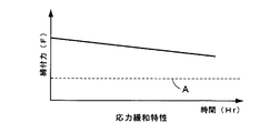
そして、加熱炉28を用いた加熱劣化工程の間、歪ゲージ20からの測定出力に基づき、締付力の変化を制御部26によって検出する。図2に示すように、検出された締付力Fは加熱時間の経過に伴い徐々に低下する。そして、締付力の低下は、試験金属ガスケット30の反発力の低下に対応しているため、試験金属ガスケットの応力緩和特性を測定することができる。
【0032】
また、上述した締付力の検出は、基準歪ゲージ43の検出値変動、つまり、温度ドリフトを考慮して行う。すなわち、高温環境下で歪ゲージを用いる場合、熱により歪ゲージの検出値が変動する恐れがある。そこで、上記加熱劣化工程の間、加熱炉28内に設けられた基準歪ゲージ43の検出値を制御部26によって測定し、加熱に起因する検出値の変動を検出する。そして、制御部26は、上記検出値変動に応じて、歪ゲージ20により測定された締付力の値を補正する。これにより、高温条件下においても、歪ゲージ20の温度ドリフトを補正し、正確な締付力の測定および応力緩和特性の評価を行うことができる。
【0033】
上記加熱劣化工程の終了後、検出ガス供給部44および漏洩検出部46により再度、漏洩検査を行う。なお、この漏洩検査は、加熱劣化工程中に任意のタイミングで行ってもよい。そして、応力緩和特性の評価は、図2に破線Aで示す漏洩限界荷重、例えば、20KN/mを指標として行い、かつ、実際に漏洩検査により確認する。
【0034】
また、本実施の形態によれば、上述した応力緩和特性の評価に連続して、試験金属ガスケット32の復元特性評価を行う。この場合、まず、第1および第2金属フランジ部材10、12を加熱炉28から取出し、その後、図3(b)、3(c)に示すように、第1および第2金属フランジ部材10、12間の隙間に、例えば6つの板状のスペーサ48を外側から挿入し互いに等間隔を置いて配置する。各スペーサ48は所定の板厚に形成され、これらのスペーサを挿入することにより第1および第2金属フランジ部材10、12間の隙間を所定の値、例えば1mmに保持する。
【0035】
続いて、スペーサ48の装着された第1および第2金属フランジ部材10、12を常温まで冷却した後、図3(a)に示すように、加圧装置50の支持治具52上に載置する。この支持治具50は荷重計52上に設けられている。また、支持治具50の上方には、押圧治具54と、この押圧治具を支持治具に向けて押圧する油圧シリンダ56とが設けられている。押圧治具54には、それぞれ金属ガスケット30の軸方向に沿った押圧治具の変位量を測定する複数の変位計58が所定の間隔を置いて取付けられている。
【0036】
そして、支持治具52上に載置された第1および第2金属フランジ部材10、12を押圧治具54および油圧シリンダ56により押圧し、前述した応力緩和評価終了時に印加されていた荷重、例えば、200KN/mと同一の荷重を試験金属ガスケットに印加する。この時、第1および第2フランジ10、12の間にはスペーサ48が挿入されているため、試験金属ガスケット30に過度の荷重が負荷されることを防止できる。
【0037】
次に、加圧装置50により加圧した状態で、ボルト14を緩め第1および第2金属フランジ部材10、12から引き抜く。この場合、複数のボルト14を1本ずつ、かつ、一定量ずつ順番に緩めて行き、試験金属ガスケット30に不均一な荷重が作用しないようにする。
【0038】
続いて、油圧シリンダ56の押圧力を徐々に減らすことにより、第1および第2金属フランジ部材10、12、および試験金属ガスケット30に作用している荷重を徐々に減らして行く。加圧により圧縮変形されていた試験金属ガスケット30は、荷重が減少すると、その復元特性により元の形状に復元して行く。その際、第1金属フランジ部材10は試験金属ガスケット30により押し上げられて変位する。
【0039】
この間、押圧治具54による押圧荷重、および金属ガスケット30の軸方向に沿った押圧治具54の変位量をそれぞれ荷重計52および変位計58によって測定する。同時に、検出ガス供給部44および漏洩検出部46を用いて、検出空間17におけるヘリウムの漏洩を検出し、試験金属ガスケット32の漏洩検査を連続的に行う。そして、ヘリウムの漏洩が検出された際の押圧荷重および変位量をそれぞれ検出する。
【0040】
その後、上述した押圧−復元のサイクルを複数回繰し、ヘリウム漏洩が検出された際の押圧荷重および変位量をそれぞれ検出する。そして、漏洩発生時の変位量および押圧荷重により試験金属ガスケット32の復元特性評価を行う。応力緩和評価に連続して復元特性を測定することにより、加熱劣化後の試験金属ガスケットについて復元特性評価を行うことができる。
【0041】
図4は、応力緩和特性評価時および復元特性評価時における、試験金属ガスケット32に作用している荷重、および第1金属フランジ部材の変位量を連続的に示している。この図において、C点は、60年使用後における試験金属ガスケット32の応力緩和点、D点は復元特性評価時における漏洩発生点をそれぞれ示している。そして、C点とD点との間の変位量aが例えば、0.1mm以上であるか否かにより、試験金属ガスケット32の復元特性の良否を評価する。なお、前述した応力緩和特性評価における変位量の測定は変位計により行う。
【0042】
以上のように構成された金属ガスケットの特性評価方法および特性評価装置によれば、第1および第2金属フランジ部材10、12、およびこれらの金属フランジ部材によって所定の締付力が負荷された試験金属ガスケット32を加熱炉内で所定時間、所定の温度で加熱することにより、円周方向に沿った熱変形のばらつきを生じることなく試験金属ガスケットおよび金属フランジ部材全体を均一に加熱することができる。これにより、試験金属ガスケット32の全周に亘って締付力を均一に作用させ、応力緩和特性を高い精度で評価することが可能となる。また、応力緩和特性の評価の間、同時に、検出ガスを用いて試験金属ガスケット32の漏洩検査を行うことができる。
【0043】
更に、加熱劣化工程の間、加熱炉28内に設けられた基準歪ゲージ43により、熱による検出値の変動を測定し、この検出値変化に応じて、歪ゲージ20により測定された締付力を補正している。そのため、高温条件下においても、歪ゲージの温度ドリフトを補正し、一層正確な測定および評価を行うことが可能となる。
【0044】
また、本実施の形態に係る特性評価方法および特性評価装置によれば、応力緩和特性の評価に続けて、金属ガスケットの復元特性を検出することにより、長期間の使用により劣化した状態の金属ガスケットについて復元特性を評価することが可能となる。
【0045】
従って、本実施の形態に係る特性評価方法および特性評価装置によれば、高温下で長期間、例えば、60年間使用した後においても優れた密閉効果を維持可能な金属ガスケットを正確に評価することができ、この金属ガスケットを用いて金属キャスク等の密閉容器を構成することにより、密閉性に優れ安全性の高い密閉容器を得ることができる。
【0046】
なお、この発明は上述した実施の形態に限定されることなく、この発明の範囲内で種々変形可能である。例えば、第1および第2金属フランジ部材は、円盤状に限定されることなく、必要に応じて変更可能であり、かつ、その材質も種々選択可能である。また、基準ボルトおよび基準歪ゲージを試験金属ガスケットと一緒に加熱炉内で加熱する構成としたが、予め基準歪ゲージのみを加熱処理してその温度ドリフトデータを取得しておき、この温度ドリフトデータを用いて締付力の検出値を補正してもよい。
【0047】
更に、復元特性評価において、圧縮工程後、印加荷重を減らして行く代わりに、第1金属フランジ部材を第2金属フランジ部材から離間する方向へ徐々に引き上げ、その際、漏洩発生点での第1金属フランジ部材の変位量を測定することにより、試験金属ガスケットの復元特性を評価してもよい。
【0048】
【発明の効果】
以上詳述したように、この発明によれば、金属ガスケットを均一に加熱劣化させることにより金属ガスケットの特性を正確に評価可能な金属ガスケットの特性評価方法および特性評価装置を提供することができる。
【図面の簡単な説明】
【図1】この発明の実施の形態に係る特性評価装置を概略的に示す断面図。
【図2】上記特性評価装置により測定した応力緩和特性を示す図。
【図3】この発明の実施の形態に係る特性評価装置における押圧装置を示す側面図、第1および第2金属フランジ部材の平面図、および第1および第2金属フランジ部材の一部を拡大して示す断面図。
【図4】上記特性評価装置による応力緩和特性評価および復元特性評価時の荷重と変位量との関係を示す図。
【符号の説明】
10…第1金属フランジ部材
12…第2金属フランジ部材
16…ボルト
20…歪ゲージ
30…試験金属ガスケット
32…Oリング
26…制御部
40…基準ボルト
43…基準歪ゲージ
44…検出ガス供給部
46…漏洩検出部
48…スペーサ
50…押圧装置[0001]
BACKGROUND OF THE INVENTION
The present invention relates to a characteristic evaluation method and an evaluation apparatus for evaluating characteristics of a metal gasket used in a sealed container for storing radioactive materials, so-called metal cask.
[0002]
[Prior art]
Highly radioactive materials typified by spent nuclear fuel are dismantled and reprocessed to recover useful materials that can be used again as fuel, such as plutonium. Usually, spent fuel is stored in a sealed container, a so-called metal cask, at a nuclear power plant, and is transported and stored in a reprocessing facility by a truck or the like. Since such spent fuel is a highly radioactive substance, the metal cask containing it has a high hermeticity and shielding property against the radioactive substance, and the hermeticity and shielding property for a long period of time. It is necessary to maintain
[0003]
In general, a metal cask is made of a metal such as stainless steel or carbon steel, and has a container body having an open upper end, and a neutron shield formed of, for example, a synthetic resin of a polymer material and covering the outer periphery of the container body The upper end opening of the container body is closed by a primary lid and a secondary lid. These primary lid and secondary lid are each bolted to the shoulder provided at the upper end of the container body, and the sealing surface between the container body and the primary lid, and the sealing surface between the container body and the secondary lid Each is provided with a metal gasket.
[0004]
[Problems to be solved by the invention]
The metal cask constructed in this way may cause an accident such as a fall or a fall during transportation or loading / unloading work. It is necessary to hold it sufficiently to ensure the sealing and shielding properties of the cask against radiation.
[0005]
Metal gaskets used for the seals of the primary and secondary lids can withstand use under high temperature and high dose conditions, and can maintain high hermeticity over a long period of time. If the lid is slightly displaced due to, etc., the sealing performance may be reduced. In particular, since the sealing ability such as stress relaxation characteristics and restoration characteristics of the metal gasket is lowered by long-term use, the sealing performance of the metal cask is greatly deteriorated by a slight displacement of the lid.
[0006]
Therefore, when using a metal gasket, it is necessary to evaluate in advance the characteristics of the metal gasket after it has been used for a long period of time and to use a metal gasket that can maintain a high sealing ability even after a long period of use.
[0007]
The present invention has been made in view of the above points. An object of the present invention is to provide a metal gasket characteristic evaluation method and a characteristic evaluation apparatus capable of evaluating the characteristics of a metal gasket with high accuracy.
[0008]
[Means for Solving the Problems]
In order to achieve the above object, a method for evaluating characteristics of a metal gasket according to the present invention includes arranging an annular metal gasket between two metal flange members arranged opposite to each other, and a plurality of bolts provided on the metal flange member. The metal flange members are clamped between the metal flange members with a predetermined tightening force by tightening the metal flange members in a direction approaching each other, and the tightening is performed by a strain gauge attached to at least one of the bolts. The metal gasket and metal flange member clamped with the predetermined tightening force are heated in a heating furnace at a predetermined temperature for a predetermined time to deteriorate the metal gasket, and the strain gauge is used to tighten the clamp. Measure the force and evaluate the stress relaxation characteristics of the metal gasket based on the measured change in the tightening force. It is characterized in.
[0009]
The metal gasket characteristic evaluation device according to the present invention includes two metal flange members disposed opposite each other with the metal gasket interposed therebetween, and a plurality of metal flange members provided along the metal flange member and tightening the two metal flange members together. Accordingly, a bolt that clamps the metal gasket between metal flange members with a predetermined tightening force, a strain gauge that is attached to at least one of the bolts and measures the tightening force, and is tightened with the predetermined tightening force And a heating furnace that heats the entire metal gasket and the metal flange member and deteriorates the metal gasket.
[0010]
According to the characteristic evaluation method and characteristic evaluation apparatus for a metal gasket configured as described above, the metal gasket and the metal flange member tightened with the predetermined tightening force are placed in a heating furnace at a predetermined temperature for a predetermined time. By heating, the metal gasket and the entire metal flange member can be uniformly heated without causing variations in thermal deformation along the circumferential direction. As a result, it is possible to uniformly apply the tightening force over the entire circumference of the metal gasket and evaluate the stress relaxation characteristics with high accuracy.
[0011]
Further, according to the method for evaluating the characteristics of the metal gasket according to the present invention, with the O-ring disposed outside the metal gasket between the two metal flange members, the stress relaxation characteristics of the metal gasket are evaluated, During the heating, a detection gas is supplied between the metal gasket and the O-ring between the two metal flange members, and the detection gas leaks in a space inside the metal gasket between the two metal flange members. It is characterized by detecting.
[0012]
Further, the metal gasket characteristic evaluation apparatus according to the present invention includes an O-ring disposed between the two metal flange members and outside the metal gasket, and the metal gasket and the O-ring between the two metal flange members. A detection gas supply unit that supplies a detection gas between the two metal flange members, and a leak detection unit that detects a leak of the detection gas in a space inside the metal gasket between the two metal flange members. Yes.
According to the above-described evaluation method and evaluation apparatus, it is possible to perform a leak inspection of the metal gasket using the detection gas at the same time during the above-described evaluation of the stress relaxation characteristics.
[0013]
Further, according to the characteristic evaluation method and characteristic evaluation apparatus for a metal gasket according to the present invention, during the heating, the detected value change due to heat is measured by a reference strain gauge provided in the heating furnace, and the detected value change Accordingly, the tightening force measured by the strain gauge is corrected. Therefore, even under high temperature conditions, the temperature drift of the strain gauge can be corrected and more accurate measurement and evaluation can be performed.
[0014]
Further, in the method for evaluating the characteristics of the metal gasket according to the present invention, an annular metal gasket and an O-ring located outside the metal gasket are arranged between two metal flange members arranged to face each other with a predetermined gap. In addition, the metal gasket is clamped between the metal flange members with a predetermined tightening force by tightening a plurality of bolts provided along the metal flange member, and is tightened with the predetermined tightening force. And the metal flange member is heated at a predetermined temperature in a heating furnace for a predetermined time to deteriorate the metal gasket, and after the heating, a spacer is disposed in the gap between the metal flange members to hold the gap, The metal gasket and the metal flange member are cooled to room temperature, and after the cooling, the metal flange member is pressed to A predetermined load is applied to the sket, and after removing the bolt in a state where the predetermined load is applied, the pressing force of the metal flange member is gradually reduced, and at that time, along the axial direction of the metal gasket While measuring the displacement amount of the metal flange member and measuring the clamping force with a strain gauge to reduce the pressing force of the metal flange member, between the metal gasket and the O-ring between the two metal flange members The detection gas is supplied between the two metal flange members, the detection gas leakage in the space inside the metal gasket is detected, and the displacement amount of the metal flange member when the detection gas leakage is detected. According to the above, the restoration characteristics of the metal gasket are evaluated.
[0015]
According to the characteristic evaluation method, the metal gasket and the metal flange member tightened with the predetermined tightening force are heated in a heating furnace at a predetermined temperature for a predetermined time, thereby causing thermal deformation along the circumferential direction. The entire metal gasket and metal flange member can be uniformly heated without causing variations in the above. As a result, it is possible to uniformly apply the tightening force over the entire circumference of the metal gasket and evaluate the stress relaxation characteristics with high accuracy. Furthermore, following the evaluation of the stress relaxation characteristics, it is possible to evaluate the restoration characteristics of the metal gasket.
[0016]
DETAILED DESCRIPTION OF THE INVENTION
Hereinafter, a characteristic evaluation method and a characteristic evaluation apparatus for a metal gasket according to an embodiment of the present invention will be described in detail with reference to the drawings.
As shown in FIG. 1, the metal gasket characteristic evaluation apparatus according to the present embodiment includes first and second
[0017]
A large number of through
[0018]
In a state of being opposed to each other, a
[0019]
Then, with the first and second
[0020]
A
Each
[0021]
On the other hand, the characteristic evaluation apparatus includes a
[0022]
Furthermore, the characteristic evaluation apparatus includes a detection
[0023]
Next, a characteristic evaluation method for evaluating the stress relaxation characteristic of the test metal gasket using the above-described characteristic evaluation apparatus will be described.
As shown in FIG. 1, first, an annular
[0024]
Further, as shown by a two-dot chain line, after inserting the plurality of plate-
[0025]
In the state where the
[0026]
Subsequently, the detection
[0027]
After confirming that there is no helium leakage, the first and second
[0028]
The heating deterioration conditions are as follows when the deterioration parameter is LMP:
LMP = T (20 + logt)
Represented by Here, T is temperature (K) and t is time (Hr).
[0029]
For example, assuming that the metal gasket is used for 60 years in an environment of 120 ° C. in actual use, the LMP of 120 ° C. × 60 years is
LMP = 393 (20 + log5256000) ≈10108
It becomes. When the
logt = (10108/473) −20, t≈24 (Hr)
It becomes. Therefore, by heating the
[0030]
In the heat deterioration using the
[0031]
Then, during the heating deterioration process using the
[0032]
Further, the above-described tightening force is detected in consideration of a detection value fluctuation of the
[0033]
After the heating deterioration process is finished, the detection
[0034]
Further, according to the present embodiment, the restoration characteristic evaluation of the
[0035]
Subsequently, after the first and second
[0036]
Then, the first and second
[0037]
Next, in a state where the pressure is applied by the
[0038]
Subsequently, by gradually reducing the pressing force of the
[0039]
During this time, the load applied by the pressing
[0040]
Thereafter, the above-described pressing-restoring cycle is repeated a plurality of times, and the pressing load and the displacement amount when helium leakage is detected are detected. Then, the restoration characteristics of the
[0041]
FIG. 4 continuously shows the load acting on the
[0042]
According to the characteristic evaluation method and characteristic evaluation apparatus for a metal gasket configured as described above, the first and second
[0043]
Further, during the heating deterioration process, the fluctuation of the detected value due to heat is measured by the
[0044]
In addition, according to the characteristic evaluation method and characteristic evaluation apparatus according to the present embodiment, the metal gasket in a state deteriorated due to long-term use is detected by detecting the restoration characteristic of the metal gasket following the evaluation of the stress relaxation characteristic. It is possible to evaluate the restoration characteristics for.
[0045]
Therefore, according to the characteristic evaluation method and characteristic evaluation apparatus according to the present embodiment, it is possible to accurately evaluate a metal gasket that can maintain an excellent sealing effect even after being used at a high temperature for a long time, for example, 60 years. By using this metal gasket to form a sealed container such as a metal cask, a sealed container having excellent sealing performance and high safety can be obtained.
[0046]
The present invention is not limited to the above-described embodiment, and various modifications can be made within the scope of the present invention. For example, the first and second metal flange members are not limited to a disk shape, but can be changed as necessary, and the materials thereof can be selected in various ways. In addition, the reference bolt and the reference strain gauge are heated together with the test metal gasket in the heating furnace. However, only the reference strain gauge is heat-treated in advance to obtain temperature drift data, and this temperature drift data is obtained. The detected value of the tightening force may be corrected using.
[0047]
Further, in the restoration characteristic evaluation, instead of decreasing the applied load after the compression step, the first metal flange member is gradually pulled up in the direction away from the second metal flange member, and at this time, the first point at the leak occurrence point is obtained. The restoring characteristic of the test metal gasket may be evaluated by measuring the displacement amount of the metal flange member.
[0048]
【The invention's effect】
As described above in detail, according to the present invention, it is possible to provide a metal gasket characteristic evaluation method and a characteristic evaluation apparatus capable of accurately evaluating the characteristics of a metal gasket by uniformly deteriorating the metal gasket by heating.
[Brief description of the drawings]
FIG. 1 is a cross-sectional view schematically showing a characteristic evaluation apparatus according to an embodiment of the present invention.
FIG. 2 is a diagram showing stress relaxation characteristics measured by the characteristic evaluation apparatus.
FIG. 3 is a side view showing a pressing device in the characteristic evaluation device according to the embodiment of the present invention, a plan view of the first and second metal flange members, and an enlarged part of the first and second metal flange members. FIG.
FIG. 4 is a diagram showing a relationship between a load and a displacement amount in stress relaxation characteristic evaluation and restoration characteristic evaluation by the characteristic evaluation apparatus.
[Explanation of symbols]
DESCRIPTION OF
Claims (9)
上記ボルトの少なくとも1本に取り付けられた歪ゲージにより上記締付力を測定し、
上記所定の締付力で締付けられた上記金属ガスケットおよび金属フランジ部材を加熱炉内で所定時間、所定の温度で加熱して上記金属ガスケットを劣化させ、上記歪ゲージにより上記締付力を測定し、測定された上記締付力の変化に基づいて上記金属ガスケットの応力緩和特性を評価することを特徴とする金属ガスケットの特性評価方法。An annular metal gasket is disposed between two opposing metal flange members and the metal gasket is tightened in a direction approaching each other by a plurality of bolts provided on the metal flange member. Sandwiched between the metal flange members with a predetermined tightening force,
Measuring the tightening force with a strain gauge attached to at least one of the bolts;
The metal gasket and metal flange member tightened with the predetermined tightening force are heated in a heating furnace at a predetermined temperature for a predetermined time to deteriorate the metal gasket, and the tightening force is measured with the strain gauge. A method for evaluating the characteristics of a metal gasket, comprising evaluating stress relaxation characteristics of the metal gasket based on the measured change in the tightening force.
上記加熱の間、上記2つの金属フランジ部材間で上記金属ガスケットとOリングとの間に検出ガスを供給し、上記2つの金属フランジ部材間で上記金属ガスケットの内側の空間における上記検出ガスの漏洩を検出することを特徴とする請求項1に記載の金属ガスケットの特性評価方法。While evaluating the stress relaxation characteristics of the metal gasket in a state where an O-ring is disposed outside the metal gasket between the two metal flange members,
During the heating, a detection gas is supplied between the metal gasket and the O-ring between the two metal flange members, and the detection gas leaks in a space inside the metal gasket between the two metal flange members. The method for evaluating characteristics of a metal gasket according to claim 1, wherein:
上記加熱の間、熱による上記基準歪ゲージの検出値変化を測定し、上記検出値変化に応じて、上記歪ゲージにより測定された上記締付力を補正することを特徴とする請求項1又は2に記載の金属ガスケットの特性評価方法。Place a reference bolt with a reference strain gauge in the furnace,
The detection value change of the reference strain gauge due to heat is measured during the heating, and the tightening force measured by the strain gauge is corrected according to the change of the detection value. 3. A method for evaluating the characteristics of the metal gasket according to 2.
上記所定の締付力で締付けられた上記金属ガスケットおよび金属フランジ部材を加熱炉内で所定時間、所定の温度で加熱して上記金属ガスケットを劣化させ、上記加熱後、上記金属フランジ部材間の隙間にスペーサを配置して上記隙間を保持するとともに、上記金属ガスケットおよび金属フランジ部材を常温に冷却し、
上記冷却後、上記金属フランジ部材を押圧して上記金属ガスケットに所定の荷重を付加し、
上記所定の荷重を付加した状態で上記ボルトを取り外した後、上記金属フランジ部材の押圧力を徐々に低減し、その際、上記金属ガスケットの軸方向に沿った上記金属フランジ部材の変位量を測定するとともに歪ゲージにより締付力を測定し、
上記金属フランジ部材の押圧力を低減する間、上記2つの金属フランジ部材間で上記金属ガスケットとOリングとの間に検出ガスを供給するとともに、上記2つの金属フランジ部材間で上記金属ガスケットの内側の空間における上記検出ガスの漏洩を検出し、
上記検出ガスの漏洩が検出された時の上記金属フランジ部材の変位量に応じて、上記金属ガスケットの復元特性を評価することを特徴とする金属ガスケットの特性評価方法。An annular metal gasket and an O-ring positioned outside the metal gasket are arranged between two metal flange members arranged to face each other with a predetermined gap, and a plurality of bolts provided on the metal flange member. By clamping the metal flange members in a direction approaching each other, the metal gasket is sandwiched between the metal flange members with a predetermined clamping force,
The metal gasket and the metal flange member tightened with the predetermined tightening force are heated in a heating furnace at a predetermined temperature for a predetermined time to deteriorate the metal gasket, and after the heating, the gap between the metal flange members The spacer is arranged to hold the gap, and the metal gasket and the metal flange member are cooled to room temperature,
After the cooling, press the metal flange member to apply a predetermined load to the metal gasket,
After removing the bolt with the predetermined load applied, the pressing force of the metal flange member is gradually reduced, and at that time, the displacement amount of the metal flange member along the axial direction of the metal gasket is measured. And measure the tightening force with a strain gauge,
While reducing the pressing force of the metal flange member, the detection gas is supplied between the two metal flange members between the metal gasket and the O-ring, and the inner side of the metal gasket between the two metal flange members. Detecting the detection gas leak in the space of
A method for evaluating a property of a metal gasket, comprising: evaluating a restoration property of the metal gasket according to a displacement amount of the metal flange member when leakage of the detection gas is detected.
上記所定の締付力で締付けられた上記金属ガスケットおよび金属フランジ部材を加熱炉内で所定時間、所定の温度で加熱して上記金属ガスケットを劣化させ、少なくとも1本の上記ボルトに取り付けられた歪ゲージにより上記締付力を測定し、
上記加熱の間、上記歪ゲージにより上記締付力を測定し、測定された上記締付力の変動に応じて上記金属ガスケットの応力緩和特性を評価し、
上記加熱後、上記金属フランジ部材間の隙間にスペーサを配置して上記隙間を保持するとともに、上記金属ガスケットおよび金属フランジ部材を常温に冷却し、
上記冷却後、上記金属フランジ部材を加圧装置に装着し、上記金属フランジ部材を両側から加圧して上記金属フランジ部材に所定の荷重を付加し、
上記所定の荷重を付加した状態で上記ボルトを取り外した後、上記金属フランジ部材に付加した荷重を徐々に低減し、その際、上記金属ガスケットの軸方向に沿った上記金属フランジ部材の変位量を測定し、
上記金属フランジ部材に付加した荷重を低減する間、上記2つの金属フランジ部材間で上記金属ガスケットとOリングとの間に検出ガスを供給するとともに、上記2つの金属フランジ部材間で上記金属ガスケットの内側の空間における上記検出ガスの漏洩を検出し、
上記検出ガスの漏洩が検出された時の上記金属フランジ部材の変位量に応じて、上記金属ガスケットの復元特性を評価することを特徴とする金属ガスケットの特性評価方法。An annular metal gasket and an O-ring positioned outside the metal gasket are arranged between two metal flange members arranged to face each other with a predetermined gap, and a plurality of bolts provided on the metal flange member. By clamping the metal flange members in a direction approaching each other, the metal gasket is sandwiched between the metal flange members with a predetermined clamping force,
The metal gasket and the metal flange member clamped with the predetermined tightening force are heated in a heating furnace at a predetermined temperature for a predetermined time to deteriorate the metal gasket, and a strain attached to at least one of the bolts. Measure the above tightening force with a gauge,
During the heating, measure the clamping force with the strain gauge, evaluate the stress relaxation characteristics of the metal gasket according to the measured variation of the clamping force,
After the heating, a spacer is disposed in the gap between the metal flange members to hold the gap, and the metal gasket and the metal flange member are cooled to room temperature,
After the cooling, the metal flange member is attached to a pressure device, the metal flange member is pressurized from both sides, and a predetermined load is applied to the metal flange member,
After removing the bolt with the predetermined load applied, the load applied to the metal flange member is gradually reduced. At this time, the displacement amount of the metal flange member along the axial direction of the metal gasket is reduced. Measure and
While reducing the load applied to the metal flange member, the detection gas is supplied between the metal gasket and the O-ring between the two metal flange members, and the metal gasket is connected between the two metal flange members. Detect the detection gas leak in the inner space,
A method for evaluating a property of a metal gasket, comprising: evaluating a restoration property of the metal gasket according to a displacement amount of the metal flange member when leakage of the detection gas is detected.
上記金属ガスケットを挟持して対向配置された2つの金属フランジ部材と、
上記金属フランジ部材に複数設けられ上記2つの金属フランジ部材同士を締付けることにより上記金属ガスケットを所定の締付力で金属フランジ部材間に挟持するボルトと、
上記ボルトの少なくとも1本に取り付けられ上記締付力を測定する歪ゲージと、
上記所定の締付力で締付けられた上記金属ガスケットおよび金属フランジ部材全体を加熱し、上記金属ガスケットを劣化させる加熱炉と、
を備えたことを特徴とする金属ガスケットの特性評価装置。In the metal gasket characteristic evaluation apparatus used for the metal gasket characteristic evaluation method of any one of Claims 1 thru | or 6,
Two metal flange members disposed opposite to each other with the metal gasket interposed therebetween;
A plurality of bolts that are provided on the metal flange member and clamp the metal gasket between the metal flange members with a predetermined tightening force by fastening the two metal flange members together;
A strain gauge attached to at least one of the bolts and measuring the tightening force;
A heating furnace that heats the entire metal gasket and the metal flange member tightened with the predetermined tightening force to deteriorate the metal gasket;
An apparatus for evaluating the characteristics of a metal gasket, comprising:
Priority Applications (1)
| Application Number | Priority Date | Filing Date | Title |
|---|---|---|---|
| JP2001171228A JP3686355B2 (en) | 2001-06-06 | 2001-06-06 | Method and apparatus for evaluating characteristics of metal gasket |
Applications Claiming Priority (1)
| Application Number | Priority Date | Filing Date | Title |
|---|---|---|---|
| JP2001171228A JP3686355B2 (en) | 2001-06-06 | 2001-06-06 | Method and apparatus for evaluating characteristics of metal gasket |
Publications (2)
| Publication Number | Publication Date |
|---|---|
| JP2002364749A JP2002364749A (en) | 2002-12-18 |
| JP3686355B2 true JP3686355B2 (en) | 2005-08-24 |
Family
ID=19013031
Family Applications (1)
| Application Number | Title | Priority Date | Filing Date |
|---|---|---|---|
| JP2001171228A Expired - Fee Related JP3686355B2 (en) | 2001-06-06 | 2001-06-06 | Method and apparatus for evaluating characteristics of metal gasket |
Country Status (1)
| Country | Link |
|---|---|
| JP (1) | JP3686355B2 (en) |
Families Citing this family (10)
| Publication number | Priority date | Publication date | Assignee | Title |
|---|---|---|---|---|
| DE102004035111A1 (en) * | 2004-07-20 | 2006-02-16 | Federal-Mogul Sealing Systems Bretten Gmbh | Testing device for sealing bodies |
| JP5297316B2 (en) * | 2009-09-15 | 2013-09-25 | 新明和工業株式会社 | Connection structure for vacuum seal and vacuum apparatus provided with this connection structure |
| CN101666700B (en) * | 2009-09-21 | 2012-11-21 | 南京工业大学 | Method and device for testing leakage rate of high-temperature sealing gasket |
| CN102435402B (en) * | 2011-12-01 | 2014-06-25 | 西北核技术研究所 | Device for detecting leak rate of sealing ring |
| CN102879156B (en) * | 2012-09-17 | 2015-11-04 | 中国石油大学(北京) | The sealing pressure-measuring method of O-ring seals and packoff thereof |
| EP2741044B1 (en) | 2012-12-05 | 2019-07-24 | Alfa Laval Corporate AB | Device, method and plate heat exchanger |
| CN107478386B (en) * | 2017-09-07 | 2023-10-20 | 重庆科技学院 | Method for testing high-temperature contact stress relaxation of special thread sealing surface |
| CN113686523B (en) * | 2021-08-25 | 2024-09-10 | 重庆川仪调节阀有限公司 | Gasket sealing performance testing method |
| CN114184483B (en) * | 2021-11-11 | 2023-10-24 | 广东科鼎功能材料有限公司 | Temperature control device for detecting functional polymer material |
| CN119952464B (en) * | 2024-12-12 | 2025-10-10 | 燕山大学 | Quick installation device for pipeline flange and use method |
-
2001
- 2001-06-06 JP JP2001171228A patent/JP3686355B2/en not_active Expired - Fee Related
Also Published As
| Publication number | Publication date |
|---|---|
| JP2002364749A (en) | 2002-12-18 |
Similar Documents
| Publication | Publication Date | Title |
|---|---|---|
| JP3686355B2 (en) | Method and apparatus for evaluating characteristics of metal gasket | |
| US4709729A (en) | Pipe weld repair device and method for the installation thereof | |
| JPH04233500A (en) | Method for monitoring installation of transportable element and sealing degree between transportable element and fixed structure and use thereof | |
| US9989496B2 (en) | Fixed value residual stress test block and manufacturing and preservation method thereof | |
| Wang et al. | Imperfection sensitivity of externally-pressurized, thin-walled, torispherical-head buckling | |
| Choiron et al. | Simulation and experimentation on the contact width of new metal gasket for asbestos substitution | |
| JP3690999B2 (en) | Metal gasket evaluation test method and evaluation test apparatus | |
| JP2006017609A (en) | Element test method of gasket for cask and its device | |
| JP2004028942A (en) | Method and device for evaluating and testing metal gasket | |
| Frano et al. | Demonstration of structural performance of IP-2 package by simulation and full-scale horizontal free drop test | |
| JP3556939B2 (en) | Cask drop test method | |
| CN117419857A (en) | Universal sealing test device and use method | |
| JP2559969B2 (en) | Method and apparatus for measuring the pressure resistance of thermoplastic synthetic resin pipes when hot | |
| Muramatsu et al. | FEM stress analysis and the sealing performance evaluation of bolted pipe flange connections with large nominal diameter subjected to internal pressure | |
| CN115728125A (en) | Small punch creep test device and system | |
| Bartonicek et al. | On the effect of temperature on tightening characteristics of gaskets | |
| Woodley | Leakage and stiffness measurements made on manhole flange and cover test assembly. Project DRAGON | |
| Nagelschmidt et al. | Long-Term Investigations of Metal Seals for Storage Casks of Radioactive Materials | |
| Namba et al. | Evaluation of Sealing Performance of Metal Gaskets Used in Dual Purpose Metal Cask under Normal Transport Condition Considering Ageing of Metal Gaskets under Long-Term Storage | |
| CN105890887B (en) | Harvard installation quality control method for steam turbine adjusting system of nuclear power station | |
| Jaszak et al. | Methodology of leakage prediction in gasketed flange joints at pipeline deformations. Materials, 2022, 15, 4354 | |
| Morgan | Comparison of experimental and theoretical stresses at a mismatch in a circumferential joint in a cylindrical pressure vessel | |
| Komann et al. | Design assessment by BAM of a new package design for the transport of SNF from a German research reactor | |
| Clauss | Failure mechanisms of LWR steel containment buildings subject to severe accident loadings | |
| Steinwarz et al. | Concept of a Prestressed Cast Iron Pressure Vessel for a Modular High Temperature Reactor |
Legal Events
| Date | Code | Title | Description |
|---|---|---|---|
| A977 | Report on retrieval |
Free format text: JAPANESE INTERMEDIATE CODE: A971007 Effective date: 20050223 |
|
| TRDD | Decision of grant or rejection written | ||
| A01 | Written decision to grant a patent or to grant a registration (utility model) |
Free format text: JAPANESE INTERMEDIATE CODE: A01 Effective date: 20050510 |
|
| A61 | First payment of annual fees (during grant procedure) |
Free format text: JAPANESE INTERMEDIATE CODE: A61 Effective date: 20050602 |
|
| LAPS | Cancellation because of no payment of annual fees |