JP3685408B2 - Disc player - Google Patents
Disc player Download PDFInfo
- Publication number
- JP3685408B2 JP3685408B2 JP2003111172A JP2003111172A JP3685408B2 JP 3685408 B2 JP3685408 B2 JP 3685408B2 JP 2003111172 A JP2003111172 A JP 2003111172A JP 2003111172 A JP2003111172 A JP 2003111172A JP 3685408 B2 JP3685408 B2 JP 3685408B2
- Authority
- JP
- Japan
- Prior art keywords
- clamper
- plate
- clamper plate
- housing
- screw
- Prior art date
- Legal status (The legal status is an assumption and is not a legal conclusion. Google has not performed a legal analysis and makes no representation as to the accuracy of the status listed.)
- Expired - Fee Related
Links
Images


Classifications
-
- G—PHYSICS
- G11—INFORMATION STORAGE
- G11B—INFORMATION STORAGE BASED ON RELATIVE MOVEMENT BETWEEN RECORD CARRIER AND TRANSDUCER
- G11B17/00—Guiding record carriers not specifically of filamentary or web form, or of supports therefor
- G11B17/02—Details
- G11B17/04—Feeding or guiding single record carrier to or from transducer unit
- G11B17/05—Feeding or guiding single record carrier to or from transducer unit specially adapted for discs not contained within cartridges
- G11B17/053—Indirect insertion, i.e. with external loading means
- G11B17/056—Indirect insertion, i.e. with external loading means with sliding loading means
-
- G—PHYSICS
- G11—INFORMATION STORAGE
- G11B—INFORMATION STORAGE BASED ON RELATIVE MOVEMENT BETWEEN RECORD CARRIER AND TRANSDUCER
- G11B17/00—Guiding record carriers not specifically of filamentary or web form, or of supports therefor
- G11B17/02—Details
- G11B17/022—Positioning or locking of single discs
- G11B17/028—Positioning or locking of single discs of discs rotating during transducing operation
- G11B17/0284—Positioning or locking of single discs of discs rotating during transducing operation by clampers
- G11B17/0285—Positioning or locking of single discs of discs rotating during transducing operation by clampers mounted on a bridge
Description
【0001】
【発明の属する技術分野】
本発明は、CD、DVDなどの光ディスクや光磁気ディスク(以下、ディスクと略称する)に対して再生や記録をするためのディスクプレーヤに関し、特に、クランパープレートの強度を大きくしたものである。
【0002】
【従来の技術】
従来、ディスクプレーヤの技術として特許文献1などに記載したものがあり、その一例を図12から図14に基づいて説明すると、ディスクD用トレイ1を矢印a,b方向に前後進可能に配置した筐体2の両側壁部2a間に前後進方向a,bとは直交する左右方向c,dに沿って渡し掛けられる鋼板製クランパープレート3の両側縁部を直角に折り曲げて略L字状補強部3aが形成され、該クランパープレート3の両端部をビス4により筐体2の両側壁部2aに止着している。図13中、5はクランパープレート3の中央に形成したガイド孔6に係合させたクランパーであって、クランパー本体5aと、該クランパー本体5aの上下端に固着した上下一対の鍔部5b,5cと、クランパー本体5aの天井面に固着したマグネット5dとからなり、クランパープレート3と下側鍔部5cとの間のクリアランスα分だけ一定範囲内上下動可能に形成されている。7は筐体2内に昇降可能に配置したターンテーブルである。
【0003】
ディスクDのローディング手順を説明すると、図12に仮想線で示すように、前進a状態のトレイ1上にディスクDを載置した後、ローディング信号に基づいてトレイ1を後退bさせることにより、図13に示すように、トレイ1上のディスクDがクランパー5及びターンテーブル7と同心状に位置決めされる。次に、ターンテーブル7をトレイ1の通過孔1aを通って上昇させることにより、該ターンテーブル7の中央突起部7aをディスクDの中心孔Daに嵌入させて該ディスクDを持ち上げることにより、図14に示すように、ディスクDによりクランパー5が押し上げられ、そのクランパー5とターンテーブル7とでディスクDをクランプし、該ターンテーブル7によりディスクDを回転させることにより、そのディスクDに記録されている情報を光ピックアップ(図示せず)により読み取る。
【0004】
出荷前の静荷重試験では、図12に仮想線で示すように、試験棒8をクランパープレート3にランダムに押し付けて所定荷重の負荷をかけることにより、該クランパープレート3が変形されるか否かをチェックして、そのクランパープレート3の強度が所定値以上であることを確認する。
【0005】
【特許文献1】
特開平9−297951号公報
【0006】
【発明が解決しようとする課題】
上記従来の構成では、クランパープレート3の強度を大きくするため、その両側縁部に補強部3aを形成しているが、該補強部3aはクランパープレート3の両側縁部を直角に折り曲げて略L字状に形成しただけであるから、その補強部3aによる強度増大量は比較的小さい。そこで、クランパープレート3として例えば0.8mm程度の比較的肉厚tが大きい鋼板を用いて、該クランパープレート3の剛性を高めているが、これでは、肉厚tの大きい鋼板を用いることにより材料費が高くつくと共に、肉厚tの大きい分だけクランパー5のクリアランスαが狭められるため、そのクリアランスαを充分に確保するために、クランパー5の高さを大きくする必要があり、これでは、ディスクプレーヤの大型化につながる。
【0007】
そこで、特開平11−54949号公報に記載の技術に基づいて、図15に示すように、クランパープレート3の両側部を複数回折り曲げて略ロ字状の補強部3bを形成することが考えられる。しかし、これでは、F2及びF4の方向の負荷に対しては強度を大きくすることができるが、F1及びF3の方向の負荷に対しては、略ロ字状補強部3b内の比較的大きな空隙部9により、強度をあまり大きくすることができない。従って、この場合にも、比較的肉厚tが大きい鋼板を用いてクランパープレート3の剛性を高くする必要がある。
【0008】
本発明は、上記従来の欠点に鑑み、あらゆる方向の負荷に対して強度を大きくしたクランパープレートを用いたディスクプレーヤを提供することを目的としている。
【0009】
【課題を解決するための手段】
上記目的を達成するため、請求項1に記載の発明は、ディスク用トレイを前後進可能に配置した筐体の両側壁部間に前後進方向とは直交する左右方向に沿って渡し掛けられる鋼板製クランパープレートの両側縁部を直角に折り曲げて略L字状補強部が形成され、該クランパープレートの両端部をビスにより筐体の両側壁部に止着しており、トレイ上のディスクを筐体内に昇降可能に配置したターンテーブルとクランパープレートの中央に形成したガイド孔に一定範囲内上下動可能に係合させたクランパーとでクランプし、ターンテーブルによりディスクを回転させて該ディスクに記録されている情報を光ピックアップで読み取るようにしたディスクプレーヤにおいて、前記略L字状補強部に代えて前記クランパープレートの両側縁部を少なくとも2重巻き以上に密に巻き込んで渦巻き状補強部が形成され、前記クランパープレートを部分的に押し曲げて前記ガイド孔の周縁部を取り囲む環状補強突条部と該環状補強突条部から該クランパープレートの両端部に向かって延びる直線状補強突条部とが形成され、前記クランパープレートの両端部の中央を下向きに折り曲げてビス受座が形成され、該ビス受座に対向して前記筐体の両側壁部に凹状受台が形成され、そのビス受座の突出幅が凹状受台の深さと同一または若干小さく設定され、前記ビス受座を凹状受台内に嵌入させ、該ビス受座を貫通して凹状受台のねじ孔にビスをねじ込むことにより、クランパープレートの両端部が筐体の両側壁部の上面に押し付けられ、前記クランパープレートの両端部に左右方向に沿って形成した一対の長孔が前記筐体の両側壁部に突設した一対の位置決め突起部にそれぞれ嵌合され、前記クランパープレートの両端部から下向きに直角に折り曲げた側板部が筐体の両側壁部の外側面に当接され、該各側板部に貫設した係止口が筐体の両側壁部の外側面に突設した係止片に着脱可能に係合されていることを特徴としている。
【0010】
上記構成は実施の一形態(図1から図8参照)に対応するものであって、これによれば、クランパープレートの両側縁部を密に巻き込んで渦巻き状補強部が形成されており、該補強部により該クランパープレートの強度が所定値以上に大きくされているので、出荷前の静荷重試験において、試験棒をクランパープレートにランダムに押し付けて所定荷重の負荷をかけた場合でも、そのクランパープレートが変形されることがなく、このクランパープレートと筐体とで強固な剛体構造を形成して、その内部に配置した光ピックアップやドライブ機構などが落下などの衝撃で損傷されないように確実に保護することができる。
【0011】
前記渦巻き状補強部内に空隙部が無いので、その補強部に対してどの方向から負荷がかかっても、その強度が低下することがない。従って、クランパープレートを従来に比べて肉厚が小さい鋼板により形成することができ、材料費を安くすることができる。また、クランパープレートの肉厚を小さくすることにより、クランパーを上下動させるためのクリアランスが拡大されるから、その拡大された分だけクランパーの高さを小さくしてディスクプレーヤの小型化を図ることもできる。
【0012】
更に、クランパープレートを部分的に押し曲げて形成した環状補強突条部と直線状補強突条部とにより、そのクランパープレートの強度を一層大きくすることができる。
【0013】
また更に、クランパープレートの両端部中央に形成したビス受座の突出幅が筐体の両側壁部に形成した凹状受台の深さと同一または若干小さく設定されているので、該ビス受座を凹状受台内に嵌入させ、そのビス受座を貫通して凹状受台のねじ孔にビスをねじ込むことにより、該クランパープレートの両端部を筐体の両側壁部の上面に確実に押し付けて、そのクランパープレートと筐体とを強固に一体連結することができる。
【0014】
しかも、クランパープレートの両端部に形成した一対の長孔を筐体の両側壁部に突設した一対の位置決め突起部にそれぞれ嵌合させると共に、該クランパープレートの両端部から下向きに直角に折り曲げた側板部を筐体の両側壁部の外側面に当接させるだけで、そのクランパープレートを前後進方向及び左右方向に位置決めすることができる。また、クランパープレートの各側板部に貫設した係止口を筐体の係止片に係合させることにより、そのクランパープレートが筐体から不測に外れないように係止することができる。
【0015】
請求項2に記載の発明は、ディスク用トレイを前後進可能に配置した筐体の両側壁部間に前後進方向とは直交する左右方向に沿って渡し掛けた鋼板製クランパープレートの両端部をビスにより筐体の両側壁部に止着しており、トレイ上のディスクを筐体内に昇降可能に配置したターンテーブルとクランパープレートの中央に形成したガイド孔に一定範囲内上下動可能に係合させたクランパーとでクランプし、ターンテーブルによりディスクを回転させて該ディスクに記録されている情報を光ピックアップで読み取るようにしたディスクプレーヤにおいて、前記クランパープレートの両側縁部を小さく重畳状に折り曲げることにより補強部が形成され、前記クランパープレートの両端部の中央を下向きに折り曲げてビス受座が形成され、該ビス受座に対向して前記筐体の両側壁部に凹状受台が形成され、そのビス受座の突出幅が凹状受台の深さと同一または若干小さく設定され、前記ビス受座を凹状受台内に嵌入させ、該ビス受座を貫通して凹状受台のねじ孔にビスをねじ込むことにより、クランパープレートの両端部が筐体の両側壁部の上面に押し付けられていることを特徴としている。
【0016】
上記構成によれば、クランパープレートの両側縁部を小さく重畳状に折り曲げて形成した補強部により該クランパープレートの強度が所定値以上に大きくされているので、出荷前の静荷重試験において、試験棒をクランパープレートにランダムに押し付けて所定荷重の負荷をかけた場合でも、そのクランパープレートが変形されることがなく、このクランパープレートと筐体とで強固な剛体構造を形成して、その内部に配置した光ピックアップやドライブ機構などが落下などの衝撃で損傷されないように確実に保護することができる。
【0017】
また、クランパープレートの両端部中央に形成したビス受座の突出幅が筐体の両側壁部に形成した凹状受台の深さと同一または若干小さく設定されているので、該ビス受座を凹状受台内に嵌入させ、そのビス受座を貫通して凹状受台のねじ孔にビスをねじ込むことにより、該クランパープレートの両端部を筐体の両側壁部の上面に確実に押し付けて、そのクランパープレートと筐体とを強固に一体連結することができる。
【0018】
【発明の実施の形態】
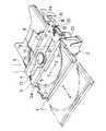
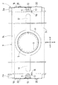
図1から図6は本発明の実施の一形態であるディスクプレーヤを示すものであって、クランパープレート3の両側縁部を3重巻きに密に巻き込んで渦巻き状補強部3cが形成され、図2に示すように、クランパープレート3を部分的に押し曲げてガイド孔6の周縁部を取り囲む環状補強突条部11と該環状補強突条部11から該クランパープレート3のの両端部に向かって延びる直線状補強突条部12とが形成され、図4及び図5に示すように、クランパープレート3の両端部の中央を下向きに折り曲げてビス受座13が形成され、該ビス受座13に対向して筐体2の両側壁部2aに凹状受台14が形成され、そのビス受座13の突出幅hが凹状受台14の深さHと同一または若干小さく設定され、該ビス受座13を凹状受台14内に嵌入させ、そのビス受座13を貫通して凹状受台14のねじ孔15にビス4をねじ込むことにより、クランパープレート3の両端部が筐体2の両側壁部2aの上面に押し付けられ、図2及び図3に示すように、クランパープレート3の両端部に左右方向c,dに沿って形成した一対の長孔16が筐体2の両側壁部2aに突設した一対の位置決め突起部17にそれぞれ嵌合され、クランパープレート3の両端部から下向きに直角に折り曲げた側板部18が筐体2の両側壁部2aの外側面に当接され、図2及び図3に示すように、各側板部18に貫設した一対の係止口19が筐体2の両側壁部2aの外側面に突設した係止片20に着脱可能に係合されている。上記以外の構成は図12から図14に示す構成とほぼ同じであるから、同一部分に同一符号を付してその説明を省略する。
【0019】
ディスクDのローディング手順は従来とほぼ同じであって、図6に示すように、ローディング信号に基づいてトレイ1を後退bさせた後、該トレイ1上のディスクDをターンテーブル7とクランパー5とでクランプし(図7参照)、ターンテーブル7によりディスクDを回転させることにより、そのディスクDに記録されている情報を光ピックアップ(図示せず)により読み取る。
【0020】
渦巻き状補強部3cの形成手順を説明すると、図9(a)に示すように、プレスにより所定形状に打ち抜いたクランパープレート3の側縁部上面に固定ブロック22を当接させ、可動ブロック23を押し上げてクランパープレート3の側縁部を略L字状に折り曲げて第1片3Aを形成し、図9(b)に示すように、クランパープレート3の側縁部下面に固定ブロック24を当接させ、可動ブロック25を押し下げて第1片3Aをクランパープレート3の側縁部に密着させ、図9(c)に示すように、クランパープレート3の側縁部上面に固定ブロック22を当接させ、可動ブロック23を押し上げてクランパープレート3の側縁部を略L字状に折り曲げて第2片3Bを形成し、図9(d)に示すように、クランパープレート3の側縁部下面に固定ブロック24を当接させ、可動ブロック25を押し下げて第2片3Bをクランパープレート3の側縁部に密着させ、以後同様の手順を繰り返すことにより、クランパープレート3の側縁部を3重巻きして、渦巻き状補強部3cを形成すればよい(図8参照)。
【0021】
上記構成によれば、クランパープレート3の両側縁部を密に巻き込んで渦巻き状補強部3cが形成されており、該補強部3cによりクランパープレート3の強度が所定値以上に大きくされているので、図1に仮想線で示すように、出荷前の静荷重試験において、試験棒8をクランパープレート3にランダムに押し付けて所定荷重の負荷をかけた場合でも、そのクランパープレート3が変形されることがなく、このクランパープレート3と筐体2とで強固な剛体構造を形成して、その内部に配置した光ピックアップやドライブ機構などが落下などの衝撃で損傷されないように確実に保護することができる。
【0022】
図8に示すように、前記渦巻き状補強部3c内に小さな隙間があるだけで従来の比較的大きな空隙部9(図15参照)に相当するものが無いので、その補強部3cに対してどの方向(F1〜F4)から負荷がかかっても、その強度が低下することがない。従って、クランパープレート3を従来に比べて例えば0.6mm以下の肉厚tが小さい鋼板により形成することができ、材料費を安くすることができる。また、クランパープレート3の肉厚tを小さくすることにより、クランパー5を上下動させるためのクリアランスα(図6参照)が拡大されるから、その拡大された分だけクランパー5の高さを小さくしてディスクプレーヤの小型化を図ることもできる。
【0023】
更に、図2に示すように、クランパープレート3を部分的に押し曲げて形成した環状補強突条部11と直線状補強突条部12とにより、そのクランパープレート3の強度を一層大きくすることができる。
【0024】
また更に、図5に示すように、クランパープレート3の両端部中央に形成したビス受座13の突出幅hが筐体2の両側壁部2aに形成した凹状受台14の深さHと同一または若干小さく設定されているので、該ビス受座13を凹状受台14内に嵌入させ、そのビス受座13を貫通して凹状受台14のねじ孔15にビス4をねじ込むことにより、該クランパープレート3の両端部を筐体2の両側壁部2aの上面に確実に押し付けて、そのクランパープレート3と筐体2とを強固に一体連結することができる。
【0025】
しかも、図2及び図3に示すように、クランパープレート3の両端部に形成した一対の長孔16を筐体2の両側壁部2aに突設した一対の位置決め突起部17にそれぞれ嵌合させると共に、該クランパープレート3の両端部から下向きに直角に折り曲げた側板部18を筐体2の両側壁部2aの外側面に当接させるだけで、そのクランパープレート3を前後進方向a,b及び左右方向c,dに位置決めすることができる。また、クランパープレート3の各側板部18に貫設した係止口19を筐体2の係止片20に係合させることにより、そのクランパープレート3を筐体2から不測に外れないように係止することができる。
【0026】
上記の実施の形態では、3重巻きの渦巻き状補強部3cを示したが、これに限定されるわけではなく、図10に示すように、その渦巻き状補強部3cを2重巻きで形成してもよい。この場合、3重巻きに比べて強度は若干小さくなるが、巻き込み回数が少なくなった分だけ、その巻き込み加工が簡単になって加工費を安くすることができる。
【0027】
また、図11(a)に示すように、クランパープレートの側縁部を二つ折りして密に重ね合わせることにより、二つ折り片3Cを形成した後、その二つ折り片3Cを中央部から略L字状に折り曲げ、図11(b)に示すように、略L字状二つ折り片3Cを更に二つ折りして密に重ね合わせて折り畳み状補強部3dを形成してもよい。この場合、折り畳み状補強部3d内に空隙部9(図15参照)が無いので、その補強部3dに対してどの方向から負荷がかかっても、その強度が低下することがない。従って、クランパープレート3を従来に比べて肉厚tが小さい鋼板により形成することができ、材料費を安くすることができる。また、クランパープレート3の肉厚tを小さくすることにより、クランパー5を上下動させるためのクリアランスαが拡大されるから、その拡大された分だけクランパー5の高さを小さくしてディスクプレーヤの小型化を図ることもできる。
【0028】
【発明の効果】
請求項1に記載の発明によれば、実施の一形態(図1から図8参照)に示すように、クランパープレートの両側縁部を密に巻き込んで渦巻き状補強部が形成されており、該補強部により該クランパープレートの強度が所定値以上に大きくされているので、出荷前の静荷重試験において、試験棒をクランパープレートにランダムに押し付けて所定荷重の負荷をかけた場合でも、そのクランパープレートが変形されることがなく、このクランパープレートと筐体とで強固な剛体構造を形成して、その内部に配置した光ピックアップやドライブ機構などが落下などの衝撃で損傷されないように確実に保護することができる。
【0029】
前記渦巻き状補強部内に空隙部が無いので、その補強部に対してどの方向から負荷がかかっても、その強度が低下することがない。従って、クランパープレートを従来に比べて肉厚が小さい鋼板により形成することができ、材料費を安くすることができる。また、クランパープレートの肉厚を小さくすることにより、クランパーを上下動させるためのクリアランスが拡大されるから、その拡大された分だけクランパーの高さを小さくしてディスクプレーヤの小型化を図ることもできる。
【0030】
更に、クランパープレートを部分的に押し曲げて形成した環状補強突条部と直線状補強突条部とにより、そのクランパープレートの強度を一層大きくすることができる。
【0031】
また更に、クランパープレートの両端部中央に形成したビス受座の突出幅が筐体の両側壁部に形成した凹状受台の深さと同一または若干小さく設定されているので、該ビス受座を凹状受台内に嵌入させ、そのビス受座を貫通して凹状受台のねじ孔にビスをねじ込むことにより、該クランパープレートの両端部を筐体の両側壁部の上面に確実に押し付けて、そのクランパープレートと筐体とを強固に一体連結することができる。
【0032】
しかも、クランパープレートの両端部に形成した一対の長孔を筐体の両側壁部に突設した一対の位置決め突起部にそれぞれ嵌合させると共に、該クランパープレートの両端部から下向きに直角に折り曲げた側板部を筐体の両側壁部の外側面に当接させるだけで、そのクランパープレートを前後進方向及び左右方向に位置決めすることができる。また、クランパープレートの各側板部に貫設した係止口を筐体の係止片に係合させることにより、そのクランパープレートが筐体から不測に外れないように係止することができる。
【0033】
請求項2に記載の発明によれば、クランパープレートの両側縁部を小さく重畳状に折り曲げて形成した補強部により該クランパープレートの強度が所定値以上に大きくされているので、出荷前の静荷重試験において、試験棒をクランパープレートにランダムに押し付けて所定荷重の負荷をかけた場合でも、そのクランパープレートが変形されることがなく、このクランパープレートと筐体とで強固な剛体構造を形成して、その内部に配置した光ピックアップやドライブ機構などが落下などの衝撃で損傷されないように確実に保護することができる。
【0034】
また、クランパープレートの両端部中央に形成したビス受座の突出幅が筐体の
両側壁部に形成した凹状受台の深さと同一または若干小さく設定されているので、該ビス受座を凹状受台内に嵌入させ、そのビス受座を貫通して凹状受台のねじ孔にビスをねじ込むことにより、該クランパープレートの両端部を筐体の両側壁部の上面に確実に押し付けて、そのクランパープレートと筐体とを強固に一体連結することができる。
【図面の簡単な説明】
【図1】 本発明の実施の一形態であるディスクプレーヤの斜視図である。
【図2】 同要部の分解斜視図である。
【図3】 同要部の平面図である。
【図4】 同要部の縦断面図である。
【図5】 図4のA−A矢視図である。
【図6】 図4のB−B矢視図である。
【図7】 同ディスククランプ状態の横断面図である。
【図8】 同渦巻き状補強部の拡大横断面図である。
【図9】 (a)〜(d)は補強部の形成手順を示す説明図である。
【図10】 補強部の変形の一例を示す拡大横断面図である。
【図11】 (a)及び(b)は補強部の変形の他の例を示す拡大横断面図である。
【図12】 従来例を示す斜視図である。
【図13】 同要部の横断面図である。
【図14】 同ディスククランプ状態の横断面図である。
【図15】 同補強部の変形例を示す拡大横断面図である。
【符号の説明】
1 トレイ
2 筐体
2a 筐体の側壁部
3 クランパープレート
3a 略L字状補強部
3c 渦巻き状補強部
3d 折り畳み状補強部
4 ビス
5 クランパー
6 ガイド孔
7 ターンテーブル
11 環状補強突条部
12 直線状補強突条部
13 ビス受座
14 凹状受台
15 ねじ孔
16 長孔
17 位置決め突起部
18 側板部
19 係止口
20 係止片
D ディスク
a,b 前後進方向
c,d 左右方向
h ビス受座の突出幅
H 凹状受台の深さ[0001]
BACKGROUND OF THE INVENTION
The present invention relates to a disc player for reproducing and recording on an optical disc such as a CD and a DVD, and a magneto-optical disc (hereinafter abbreviated as a disc), and particularly increases the strength of a clamper plate.
[0002]
[Prior art]
Conventionally, as a technique of a disc player, there is one described in
[0003]
The loading procedure of the disk D will be described. As shown by the phantom line in FIG. 12, after the disk D is placed on the
[0004]
In the static load test before shipment, whether or not the
[0005]
[Patent Document 1]
JP-A-9-297951 [0006]
[Problems to be solved by the invention]
In the above conventional configuration, in order to increase the strength of the
[0007]
Therefore, based on the technique described in Japanese Patent Application Laid-Open No. 11-54949, as shown in FIG. 15, it is conceivable to form a substantially square-shaped reinforcing
[0008]
An object of the present invention is to provide a disc player using a clamper plate that has increased strength against loads in all directions in view of the above-described conventional drawbacks.
[0009]
[Means for Solving the Problems]
In order to achieve the above-mentioned object, the invention according to
[0010]
The above-described configuration corresponds to an embodiment (see FIGS. 1 to 8), and according to this, a spiral reinforcing portion is formed by tightly winding both side edges of the clamper plate, Since the strength of the clamper plate is increased to a predetermined value or more by the reinforcing part, even if the test rod is randomly pressed against the clamper plate and applied with a predetermined load in the static load test before shipment, the clamper plate The clamper plate and the housing form a rigid structure that is not deformed, and the optical pickup and drive mechanism placed inside the clamper plate and the housing are reliably protected from being damaged by impact such as dropping. be able to.
[0011]
Since there is no gap in the spiral reinforcing part, the strength does not decrease no matter which direction the load is applied to the reinforcing part. Therefore, the clamper plate can be formed of a steel plate having a smaller thickness than the conventional one, and the material cost can be reduced. Also, by reducing the wall thickness of the clamper plate, the clearance for moving the clamper up and down is expanded, so the height of the clamper can be reduced by that amount to reduce the size of the disc player. it can.
[0012]
Furthermore, the strength of the clamper plate can be further increased by the annular reinforcing protrusion and the linear reinforcing protrusion formed by partially pushing and bending the clamper plate.
[0013]
Furthermore, since the projecting width of the screw seat formed at the center of both ends of the clamper plate is set to be the same as or slightly smaller than the depth of the recessed seat formed on both side walls of the housing, the screw seat is formed in a concave shape. By inserting the screw into the cradle and screwing the screw into the screw hole of the concave cradle through the screw seat, the both ends of the clamper plate are securely pressed against the upper surface of the both side walls of the housing. The clamper plate and the housing can be firmly and integrally connected.
[0014]
In addition, the pair of long holes formed at both ends of the clamper plate are respectively fitted to the pair of positioning projections projecting from both side walls of the casing, and bent downward at right angles from both ends of the clamper plate. The clamper plate can be positioned in the forward / backward direction and the left / right direction simply by bringing the side plate portion into contact with the outer surfaces of the side wall portions of the casing. In addition, by engaging a locking port provided in each side plate portion of the clamper plate with a locking piece of the casing, the clamper plate can be locked so as not to be accidentally detached from the casing.
[0015]
The invention according to
[0016]
According to the above configuration, the strength of the clamper plate is increased to a predetermined value or more by the reinforcing portion formed by bending both side edges of the clamper plate in a small overlapping manner. Even when a predetermined load is applied by pressing the clamper plate randomly, the clamper plate will not be deformed, and this clamper plate and housing form a rigid structure that is placed inside Thus, the optical pickup and the drive mechanism can be reliably protected from being damaged by an impact such as dropping.
[0017]
In addition, since the protruding width of the screw seats formed at the center of both ends of the clamper plate is set to be the same as or slightly smaller than the depth of the concave seats formed on the both side walls of the housing, the screw seats can be The clamper is inserted into the base and screwed into the screw hole of the concave base through the screw receiving seat, so that both end portions of the clamper plate are securely pressed against the upper surfaces of both side wall portions of the housing. The plate and the housing can be firmly and integrally connected.
[0018]
DETAILED DESCRIPTION OF THE INVENTION
1 to 6 show a disc player according to an embodiment of the present invention, in which both side edges of a
[0019]
The loading procedure of the disk D is almost the same as that of the prior art. As shown in FIG. 6, after the
[0020]
The procedure for forming the
[0021]
According to the above configuration, the
[0022]
As shown in FIG. 8, there is nothing corresponding to the conventional relatively large gap 9 (see FIG. 15) with only a small gap in the
[0023]
Furthermore, as shown in FIG. 2, the strength of the
[0024]
Furthermore, as shown in FIG. 5, the protruding width h of the
[0025]
In addition, as shown in FIGS. 2 and 3, the pair of
[0026]
In the above embodiment, the triple spiral reinforced
[0027]
Further, as shown in FIG. 11 (a), the side edge of the clamper plate is folded in two and closely overlapped to form the two-folded
[0028]
【The invention's effect】
According to the first aspect of the present invention, as shown in one embodiment (see FIGS. 1 to 8), both sides of the clamper plate are tightly wound to form a spiral reinforcing portion, Since the strength of the clamper plate is increased to a predetermined value or more by the reinforcing part, even if the test rod is randomly pressed against the clamper plate and applied with a predetermined load in the static load test before shipment, the clamper plate The clamper plate and the housing form a rigid structure that is not deformed, and the optical pickup and drive mechanism placed inside the clamper plate and the housing are reliably protected from being damaged by impact such as dropping. be able to.
[0029]
Since there is no gap in the spiral reinforcing part, the strength does not decrease no matter which direction the load is applied to the reinforcing part. Therefore, the clamper plate can be formed of a steel plate having a smaller thickness than the conventional one, and the material cost can be reduced. Also, by reducing the wall thickness of the clamper plate, the clearance for moving the clamper up and down is expanded, so the height of the clamper can be reduced by that amount to reduce the size of the disc player. it can.
[0030]
Furthermore, the strength of the clamper plate can be further increased by the annular reinforcing protrusion and the linear reinforcing protrusion formed by partially pushing and bending the clamper plate.
[0031]
Furthermore, since the protruding width of the screw receiving seat formed at the center of both ends of the clamper plate is set to be the same as or slightly smaller than the depth of the recessed receiving base formed on the both side walls of the housing, the screw receiving seat is recessed. By inserting the screw into the cradle and screwing the screw into the screw hole of the concave cradle through the screw seat, the both ends of the clamper plate are securely pressed against the upper surface of the both side walls of the housing. The clamper plate and the housing can be firmly and integrally connected.
[0032]
In addition, the pair of long holes formed at both ends of the clamper plate are respectively fitted to the pair of positioning projections projecting from both side walls of the casing, and bent downward at right angles from both ends of the clamper plate. The clamper plate can be positioned in the forward / backward direction and the left / right direction simply by bringing the side plate portion into contact with the outer surfaces of the side wall portions of the casing. In addition, by engaging a locking port provided in each side plate portion of the clamper plate with a locking piece of the casing, the clamper plate can be locked so as not to be accidentally detached from the casing.
[0033]
According to the second aspect of the present invention, since the strength of the clamper plate is increased to a predetermined value or more by the reinforcing portion formed by bending the both side edges of the clamper plate in a small overlapping manner, the static load before shipment is increased. In the test, even when a test rod is randomly pressed against the clamper plate and a predetermined load is applied, the clamper plate is not deformed, and this clamper plate and the casing form a strong rigid body structure. In addition, the optical pickup and the drive mechanism disposed in the interior can be reliably protected from being damaged by an impact such as dropping.
[0034]
In addition, since the protruding width of the screw seats formed at the center of both ends of the clamper plate is set to be the same as or slightly smaller than the depth of the concave seats formed on the both side walls of the housing, the screw seats can be The clamper is inserted into the base and screwed into the screw hole of the concave base through the screw receiving seat, so that both end portions of the clamper plate are securely pressed against the upper surfaces of both side wall portions of the housing. The plate and the housing can be firmly and integrally connected.
[Brief description of the drawings]
FIG. 1 is a perspective view of a disc player according to an embodiment of the present invention.
FIG. 2 is an exploded perspective view of the main part.
FIG. 3 is a plan view of the main part.
FIG. 4 is a longitudinal sectional view of the main part.
FIG. 5 is a view taken in the direction of arrows AA in FIG. 4;
6 is a view taken along arrow BB in FIG. 4;
FIG. 7 is a cross-sectional view of the disc clamp state.
FIG. 8 is an enlarged cross-sectional view of the spiral reinforcing part.
FIGS. 9A to 9D are explanatory views showing a procedure for forming a reinforcing portion. FIGS.
FIG. 10 is an enlarged cross-sectional view showing an example of deformation of a reinforcing portion.
FIGS. 11A and 11B are enlarged cross-sectional views showing other examples of deformation of the reinforcing portion. FIGS.
FIG. 12 is a perspective view showing a conventional example.
FIG. 13 is a cross-sectional view of the main part.
FIG. 14 is a cross-sectional view of the disc clamp state.
FIG. 15 is an enlarged cross-sectional view showing a modification of the reinforcing part.
[Explanation of symbols]
DESCRIPTION OF
Claims (2)
Priority Applications (2)
| Application Number | Priority Date | Filing Date | Title |
|---|---|---|---|
| JP2003111172A JP3685408B2 (en) | 2003-04-16 | 2003-04-16 | Disc player |
| US10/824,608 US7392528B2 (en) | 2003-04-16 | 2004-04-15 | Clamper plate of a disk player |
Applications Claiming Priority (1)
| Application Number | Priority Date | Filing Date | Title |
|---|---|---|---|
| JP2003111172A JP3685408B2 (en) | 2003-04-16 | 2003-04-16 | Disc player |
Publications (2)
| Publication Number | Publication Date |
|---|---|
| JP2004318995A JP2004318995A (en) | 2004-11-11 |
| JP3685408B2 true JP3685408B2 (en) | 2005-08-17 |
Family
ID=33307920
Family Applications (1)
| Application Number | Title | Priority Date | Filing Date |
|---|---|---|---|
| JP2003111172A Expired - Fee Related JP3685408B2 (en) | 2003-04-16 | 2003-04-16 | Disc player |
Country Status (2)
| Country | Link |
|---|---|
| US (1) | US7392528B2 (en) |
| JP (1) | JP3685408B2 (en) |
Families Citing this family (5)
| Publication number | Priority date | Publication date | Assignee | Title |
|---|---|---|---|---|
| JP3685408B2 (en) * | 2003-04-16 | 2005-08-17 | 船井電機株式会社 | Disc player |
| JP2007265521A (en) * | 2006-03-28 | 2007-10-11 | Orion Denki Kk | Recording/reproducing device |
| JP2007280489A (en) * | 2006-04-05 | 2007-10-25 | Orion Denki Kk | Recording and reproducing device |
| TWI350535B (en) * | 2007-12-25 | 2011-10-11 | Quanta Storage Inc | Rack structure in otical disk drive |
| JP2011090096A (en) * | 2009-10-21 | 2011-05-06 | Panasonic Corp | Portable terminal device |
Family Cites Families (16)
| Publication number | Priority date | Publication date | Assignee | Title |
|---|---|---|---|---|
| US4996615A (en) * | 1987-12-04 | 1991-02-26 | Alps Electric Co., Ltd. | Head assembly |
| JPH07235173A (en) | 1994-02-18 | 1995-09-05 | Alps Electric Co Ltd | Recorder/reproducer |
| JPH07279916A (en) | 1994-04-07 | 1995-10-27 | Teac Corp | Member connecting structure |
| JPH0951153A (en) | 1995-08-07 | 1997-02-18 | Hitachi Ltd | Structure of printed board assembly |
| JP3651502B2 (en) | 1995-09-27 | 2005-05-25 | ミツミ電機株式会社 | Disk driver |
| JPH09297951A (en) | 1996-05-01 | 1997-11-18 | Sony Corp | Chucking device |
| JPH1154949A (en) | 1997-08-01 | 1999-02-26 | Kawamura Electric Inc | Enclosure for housing electric equipment |
| US6438087B2 (en) * | 1997-11-25 | 2002-08-20 | Sony Corporation | Chucking device for disc drive |
| JPH11193035A (en) | 1997-12-29 | 1999-07-21 | Katsumi Kuroda | Grip piece for packaging container handle, packaging container handle and packaging container |
| US6205113B1 (en) * | 1998-08-18 | 2001-03-20 | Iomega Corporation | Plastic clamp with hub and platter for use in disc drive |
| DE60140668D1 (en) * | 2000-05-22 | 2010-01-14 | Clarion Co Ltd | TURNTABLE |
| KR20030003295A (en) * | 2000-05-22 | 2003-01-09 | 시게이트 테크놀로지 엘엘씨 | Disc-drive mounting using adhesive films |
| JP3578333B2 (en) * | 2000-08-23 | 2004-10-20 | 船井電機株式会社 | Disc player chucking device |
| JP3913499B2 (en) * | 2001-03-22 | 2007-05-09 | アルパイン株式会社 | Disk unit |
| JP4269132B2 (en) * | 2001-06-27 | 2009-05-27 | 日本発條株式会社 | Disk drive suspension |
| JP3685408B2 (en) * | 2003-04-16 | 2005-08-17 | 船井電機株式会社 | Disc player |
-
2003
- 2003-04-16 JP JP2003111172A patent/JP3685408B2/en not_active Expired - Fee Related
-
2004
- 2004-04-15 US US10/824,608 patent/US7392528B2/en not_active Expired - Fee Related
Also Published As
| Publication number | Publication date |
|---|---|
| US7392528B2 (en) | 2008-06-24 |
| JP2004318995A (en) | 2004-11-11 |
| US20040218482A1 (en) | 2004-11-04 |
Similar Documents
| Publication | Publication Date | Title |
|---|---|---|
| US7555762B2 (en) | Clamp mechanism for disk-shaped recording medium and reproducing apparatus for the recording medium | |
| JP3685408B2 (en) | Disc player | |
| EP1675114A2 (en) | Electronic apparatus including a disc apparatus | |
| JPWO2005098850A1 (en) | Recording medium playback device | |
| US6826772B2 (en) | Disk clamping apparatus for disk player | |
| JP4088327B2 (en) | Movement restriction device, method and processing device | |
| JP2006338776A (en) | Disk clamping mechanism | |
| US7565670B2 (en) | Disk clamping mechanism having improved vibration resistance | |
| JP3389977B2 (en) | Board storage box | |
| JP2007109363A (en) | Disk device and disk medium reproducing device or disk medium recording/reproducing device | |
| JP2007066429A (en) | Clamper of recording/reproducing apparatus, and recording/reproducing apparatus with the clamper | |
| JP2010205310A (en) | Chassis structure and electronic equipment | |
| JP4154210B2 (en) | Magazine for disc changer | |
| JP2005149629A (en) | Disk device and recording disk mounting method | |
| JP2009170042A (en) | Clamp device, and disk device | |
| JP2003346591A (en) | Push switch | |
| JP4051951B2 (en) | Disk unit | |
| JP2007149270A (en) | Disk device equipped with rib for preventing entering of disk medium | |
| JPH07320440A (en) | Housing device of recording medium | |
| US20090172716A1 (en) | Disk Device | |
| US20080025184A1 (en) | Information Recording Medium Playback Apparatus | |
| JP2923271B2 (en) | Disk storage magazine | |
| JP2006114133A (en) | Cover opening/closing mechanism and optical disk device | |
| JP2015026407A (en) | Electronic device and fixing structure | |
| JPH09330541A (en) | Disc tray assembly and disc player using the same |
Legal Events
| Date | Code | Title | Description |
|---|---|---|---|
| A977 | Report on retrieval |
Free format text: JAPANESE INTERMEDIATE CODE: A971007 Effective date: 20050214 |
|
| A131 | Notification of reasons for refusal |
Free format text: JAPANESE INTERMEDIATE CODE: A131 Effective date: 20050304 |
|
| A521 | Request for written amendment filed |
Free format text: JAPANESE INTERMEDIATE CODE: A523 Effective date: 20050413 |
|
| TRDD | Decision of grant or rejection written | ||
| A01 | Written decision to grant a patent or to grant a registration (utility model) |
Free format text: JAPANESE INTERMEDIATE CODE: A01 Effective date: 20050513 |
|
| A61 | First payment of annual fees (during grant procedure) |
Free format text: JAPANESE INTERMEDIATE CODE: A61 Effective date: 20050526 |
|
| R150 | Certificate of patent or registration of utility model |
Free format text: JAPANESE INTERMEDIATE CODE: R150 |
|
| FPAY | Renewal fee payment (event date is renewal date of database) |
Free format text: PAYMENT UNTIL: 20080610 Year of fee payment: 3 |
|
| FPAY | Renewal fee payment (event date is renewal date of database) |
Free format text: PAYMENT UNTIL: 20090610 Year of fee payment: 4 |
|
| FPAY | Renewal fee payment (event date is renewal date of database) |
Free format text: PAYMENT UNTIL: 20100610 Year of fee payment: 5 |
|
| FPAY | Renewal fee payment (event date is renewal date of database) |
Free format text: PAYMENT UNTIL: 20110610 Year of fee payment: 6 |
|
| FPAY | Renewal fee payment (event date is renewal date of database) |
Free format text: PAYMENT UNTIL: 20110610 Year of fee payment: 6 |
|
| FPAY | Renewal fee payment (event date is renewal date of database) |
Free format text: PAYMENT UNTIL: 20120610 Year of fee payment: 7 |
|
| FPAY | Renewal fee payment (event date is renewal date of database) |
Free format text: PAYMENT UNTIL: 20120610 Year of fee payment: 7 |
|
| FPAY | Renewal fee payment (event date is renewal date of database) |
Free format text: PAYMENT UNTIL: 20130610 Year of fee payment: 8 |
|
| LAPS | Cancellation because of no payment of annual fees |