JP3684342B2 - Transfer device and image forming apparatus using the same - Google Patents
Transfer device and image forming apparatus using the same Download PDFInfo
- Publication number
- JP3684342B2 JP3684342B2 JP2001260674A JP2001260674A JP3684342B2 JP 3684342 B2 JP3684342 B2 JP 3684342B2 JP 2001260674 A JP2001260674 A JP 2001260674A JP 2001260674 A JP2001260674 A JP 2001260674A JP 3684342 B2 JP3684342 B2 JP 3684342B2
- Authority
- JP
- Japan
- Prior art keywords
- transfer
- roller
- image
- drum
- sheet
- Prior art date
- Legal status (The legal status is an assumption and is not a legal conclusion. Google has not performed a legal analysis and makes no representation as to the accuracy of the status listed.)
- Expired - Fee Related
Links
Images


Description
【0001】
【発明の属する技術分野】
本発明は、電子複写機、プリンター、ファクシミリ等の画像形成装置に組み込まれ、該装置に内蔵の感光体ドラムの表面に形成されたトナー画像を転写紙等のシート状物に転写する転写装置に関するものである。
【0002】
【従来の技術】
従来より電子写真複写機等において感光体ドラム等の静電像担持体の表面に形成されたトナー画像の静電転写を行う装置としては、感光体側に転写電荷を供給する手段としてコロナ放電器を用いた非接触型のコロナ転写方式以外にも、導電ローラを用いたローラ転写方式やベルト転写方式によるものが代表的である。これらローラ部材やベルト部材と感光体ドラムとの接触状態としては、接触させて使用する形態以外にも非接触とする形態のものが挙げられる。さらに非接触形態には、通紙時にはシート材を介して接触するものと、接触しないものも用いられる。
【0003】
図1に、ローラ転写装置の1例を示す。ここでは、転写装置はカーボンやアルカリ金属を分散させ導電性を持たせたウレタン樹脂等からなる転写ローラ21を感光体ドラム20に対向する位置に配設してあり、該ドラム20と転写ローラ21との周面間に進入して来た転写用紙Pを転写ローラ21によってドラム表面のトナーに圧接させるとともに、転写ローラ21の軸心にトナーと逆極性の転写電圧を印可してドラム20表面のトナー画像を用紙Pに転写するものである。かかるローラ転写装置では転写部において優れた転写効率、分離効果を得ることができること、構造が簡単であることなどから低中速機での普及が進んでいる。
【0004】
次に、図2においてベルト転写装置の1例を示す。駆動ローラ24、従動ローラ25によって張設された転写搬送ベルト23(以下、転写ベルトと称す)を感光体ドラムと同速度をもって回転するようにしている。シート材Pは転写ベルト23と密着しながら搬送され、転写部を通過し転写部では転写ベルト23と一体的に感光体ドラム22に接触するように構成されている。そして転写部では転写ベルトの内側に設けられたバイアスローラ26によって転写ベルトにトナー極性とは逆極性の電荷が付与され、感光体ドラム上のトナー像がシート材に転写するように構成されている。かかるベルト転写装置では転写部において優れた転写効率、分離効果を得ることができること、また、ベルト自体のクリーニング機構を設けることが容易であって長寿命化が可能であること等から中高速機での普及が進んでいる。
【0005】
ところが、画像形成を繰り返すうちにトナー飛散やトナー消費量増大などの問題を生じ、機内清掃等が早期に必要となり、メンテナンスサイクルを短縮せざるを得ないなどの問題が生ずる場合がある。この不具合を調査するうちに転写ローラ或いは転写ベルト等の転写部材と対向する感光体表面のうち最大の通紙ペーパー幅の外部に位置する非通紙域の部分の感光層が周方向に異常摩耗しており、クリーニング部を通過する直前の感光体の非通紙部分表面に白色粉が散在していたことが見出された。感光体表面の異常摩耗の起こるメカニズムに関して下記のように考えている。
【0006】
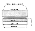
図3に示すように通常、転写ローラの軸方向の前端部と後端部は感光体ドラムの最大幅の通紙領域と非通紙領域の境界線上に含まれるか或いは前記境界線から非通紙領域側に若干はみ出すようにローラ軸長と取り付け位置が設定されている。反転現像方式においては、転写ローラ電荷が感光体表面の主帯電極性と逆極性であるから、転写ローラからの注入電荷に直接暴露される前記非通紙部分は主帯電電位と逆極性に帯電される。このような画像形成が連続的に多数枚継続すると主帯電が行われた後の非通紙部分の主帯電が不充分となり、表面電位が低下し現像バイアス電圧に近づくことになる。
【0007】
現像ローラ上に担持され感光体上の静電潜像に供給される現像剤の磁気ブラシは現像ローラー軸方向両端部のブラシ形成が不十分なために最大幅の通紙領域を超えるように設定されているから非通紙部分をも摺擦している。しかしながら、この非通紙部分の表面電位が現像バイアス電圧と同等以下にまで低下していることから、トナーが強制的に現像されることになる為に、トナー消費量の増大を招いてしまう。
【0008】
また、感光体の非通紙部に現像付着したトナーは転写ローラからの注入電荷に直接曝される内に、トナー表面の外添剤として使われるシリカ、酸化チタン、マグネタイト、アルミナなどの金属酸化物部粉末が脱離し感光体表面に強固に付着する。前記の金属微粉末は研磨作用があるためにクリーニングする際に感光体表面を削ることとなる。前記異常摩耗部分は帯電能力が失われているので、主帯電による表面電位がゼロもしくは大きく低下することになる。現像バイアス電圧よりも前記異常摩耗部分の表面電位差が大きく下回ることから現像ローラ上の現像剤からトナーが感光体側に大量に強制的に現像されトナー消費量の増大或いは甚だしい場合にはトナー飛散等を生ずる。この摩耗部分の微小亀裂は通紙領域内にまで拡大しやすく、その結果通紙領域内であっても帯電能の失われた部分が広がる事になるので前記不具合が加速されたり地肌かぶりを生じたりする。このような不具合は、ローラ転写方式とベルト転写方式の何れにおいても、或いは、非通紙時において転写部材と感光体の接触、非接触の何れにおいても発生し、メンテサイクルを縮める結果となるので、早期の解決が望まれてきた。
【0009】
【発明が解決しようとする課題】
そこで本発明の第一の目的は、上記課題に鑑みて、画像不具合やトナー飛散やトナー消費量増大などの問題を生ずることなく、機内清掃のメンテサイクルを延長できることである。
さらに、本発明の第二の目的は、感光体を局部的に磨耗させることなく高寿命化を図ることである。
【0010】
【課題を解決するための手段】
課題を解決するための請求項1の発明は、静電像担持体表面のトナー画像をシート材に転移させる為の転写部材としてローラ部材或いはベルト部材を用いた非接触転写装置において、シート材の通紙方向に対して垂直方向にみた場合の、前記転写部材による転写領域の前端部と後端部が、対向する像担持体の最大幅の有効画像領域とその周囲の非画像領域との境界線上あるいは非画像領域側に位置するように配設されるとともに、静電像担持体表面の最大幅の通紙領域とその外側の非通紙領域との境界線上あるいは、通紙領域側に位置するように配設されていることを特徴とする。
さらに請求項2の発明は、像担持体上の静電潜像をトナーで可視像化する反転現像方式の現像手段と、請求項1に記載の転写装置を用いたことを特徴とする画像形成装置である。
【0011】
請求項1、2の発明によれば、反転現像での主帯電と逆極性の転写電荷の内、最大用紙サイズを越えた感光体の領域への非接触転写部材からの転写電荷による微小コロナ放電の暴露や、転写電荷の注入などを抑制する。その結果、画像形成を繰り返した場合において、非通紙部分の主帯電が不充分となり表面電位が低下し現像バイアス電圧に近づくことを防止することができるので、この領域のトナー付着やトナー外添剤の付着などを防止することができる。さらには、トナー外添剤の付着による感光体の感光層の異常磨耗をも防止することができる。そして、通常の使用では最大サイズ(例:A3サイズ)の用紙のみを使用する訳ではない、たとえば、最大幅より幅狭の用紙(例:A4サイズ)の場合においても、この領域(A4幅=210mmより広く、A3幅=297mmより狭い範囲)のトナーやトナー外添剤の転写材への付着を防止することが非接触転写装置を用いることで可能となる。また、最大サイズの転写シート上に最大サイズの有効画像領域を得ようとする場合、非接触転写部材の端部から常時微小コロナ放電が直接感光体表面を暴露することを防止しつつ、最小限のプリントマージンは確保できるので画像欠陥を防止することができる。
【0012】
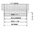
ここで、最大幅の有効画像領域とは最大複写サイズのトナー画像が転写される相手の最大サイズの転写用シートの通紙領域から周辺部のプリントマージン幅を除いたものであり、通常は最大サイズの転写シート外周部の5乃至は10mmの余白を除いた部分となる。また最大幅の通紙領域とは、前記の最大サイズの転写用シート領域のことである。図3に明らかにしたように従来の転写ローラが最大幅の通紙領域を超えていたのに対して、図4に明らかにしたように本発明においては最大の有効画像領域以上、最大幅の通紙領域以下となるように転写ローラの軸長、取り付け位置を設定する。
【0013】
【発明の実施の形態】
以下本発明の実施の形態を図面を参照して説明する。図5は本発明の画像形成装置の1実施形態の概要を模式的に描いたものである。この画像形成装置は現像手段として反転現像方式、転写手段としてローラ転写方式を用いたもので、複写速度はA4サイズで13枚/分である。1は静電像担持体としての感光体ドラムであって、アルミニウム等の金属製素管の表面に有機感光体材料からなる感光層を形成してなるものである。感光体ドラムは転写域において転写用紙Pの搬送方向と順方向になるように図略の駆動手段によって回転駆動される。感光体ドラム周面にはその回転方向に従って帯電手段3、露光手段4、現像手段5、転写手段6、クリーニング手段7及び除電手段8がその順序で配設されている。
【0014】
上記のような構成を備えた複写機においては、帯電手段3でコロナ放電によってドラム1の表面感光層が+700Vに帯電される。帯電されたドラム表面にはレーザー発生源を有する露光手段4によって、機内において設けられた光学手段(図略)によって読み取られた原稿画像に応じた光照射が行われて感光体ドラム表面に未露光部の+700Vと露光部の+120Vからなる静電線像が形成される。この静電潜像には現像手段によって、帯電トナーが付着されてトナー像が形成される。現像手段5には平均粒子径90μmの磁性キャリア95重量部と、平均粒子径9μmの正帯電性トナー5重両部を混合してなる収納される現像剤が収納され、現像ローラ5aに500Vの現像バイアスが印加されているために、正帯電性トナーは、露光部に対して現像され感光体表面にトナー画像が形成される。正帯電性トナーの表面には流動性、帯電性を改善するための酸化チタン、シリカを各々0.2重量部(トナー100重両部に対して)を分散付着させてある。
【0015】
感光体ドラム表面に形成されたトナー画像が転写手段6と対向する位置にまで回転移動してくると、レジストローラ対9によってトナー画像と同期して搬送されてくる転写シートPの表面上に感光体ドラム表面のトナー画像が転写される。転写手段6におけるトナー像転写については後で更に詳述する。感光体表面の未転写残留トナーはクリーニング手段7において感光体ドラム表面に当接せしめられるクリーニングゴムブレード7aによって感光体表面から除去される。その後除電手段8において、除電光L2が照射されて除電され、前回の帯電時からドラム1が丁度1回転したところで次の画像形成に備えられる。一方トナー像が転写された用紙Pは定着ローラ対に送られ、定着ローラ10間を通過する間に加熱、加圧され用紙P上にトナー像が定着される。
【0016】
転写手段6が具備する転写ローラ11は、ドラム1の下方においてドラム1の表面と、用紙搬送経路Bを挟んで用紙Pの厚みよりも大きな間隙をもって近接対向する位置にドラム軸と平行に配設されている。転写ローラ11は対向するドラム面と順方向に回転駆動されており、その回転周速度はドラムの回転周速度とほぼ同一である。前記間隙は転写シートPの厚みよりも大きく設定されていることが重要であり一般的には0.2乃至2.0mm程度であることが好ましい。この転写ローラ11は転写時においてドラム表面に付着した帯電トナーとは逆極性の電圧が印加されることにより、ドラム表面に付着した帯電トナーを用紙Pに転移させるものである。
【0017】
図4、図5を参照しつつ、本発明の転写ローラの軸長及び前端部、後端部の取り付け位置について詳述する。転写ローラ11は少なくとも、ローラ本体11aを回転軸11b周りに一体的に固着してなる長軸ローラ状に形成されている。転写ローラ本体11aは軸方向の長さがドラム表面のトナー像が形成される有効画像領域1aの軸方向長さと同等以上の長さであって、しかも使用する最大サイズの転写シートの感光体軸方向の長さと同等以下の長さであることが必要である。更には、転写ローラ本体11aの軸方向の前後端部が、対向する感光体の前記有効画像領域と軸方向外側の非画像領域との境界線上もしくは、境界線を超えて軸方向外側の非画像領域に位置するように配設されることが必要である。更には、転写ローラ本体11aの軸方向の前後端部が、最大サイズの転写シートの感光体表面の通紙領域と軸方向非通紙領域の境界線上に位置するかあるいは境界線を越えて軸方向内側の通紙領域にあるように配設されことが本発明の目的を達成する上で必須である。上記の構成によって、最大サイズの転写シート上に最大サイズの有効画像領域を得ようとする場合、非接触転写ローラの端部から常時微小コロナ放電が直接感光体表面を暴露することを防止しつつ、最小限のプリントマージンは確保できるので画像欠陥を防止することができる。仮に、小サイズの転写シートがかなり混合使用されて非接触転写ローラから感光体表面へのコロナ放電の直接暴露が増大したとしても、最大サイズの転写シートがたまにでも使われるだけで、非接触転写ローラ端部付近の表面電位低下が防止できるので本発明の効果が得られるのである。
【0018】
転写ローラ11のローラ本体11aとしては、例えばカーボンやアルカリ金属を分散混合したポリスチレン樹脂やウレタン樹脂のような導電性樹脂材料や導電性ゴム材料等により形成することができる。12は転写ローラ11に電圧を供給する電源であって絶対値で2000乃至3000Vの印加電圧が適切であって本実施例では2100Vとした。
【0019】
前記レジストローラ対9とドラム1との間には上下のガイド部材13、14が用紙搬送経路Bを挟んで対向する状態で配設され、また転写ローラ11よりも用紙搬送方向下流側となる用紙搬送経路B上にはガイドテーブル15が配設されている。16はガイドテーブル15と定着ローラ対10との間に配設された用紙ガイドである。前記下側ガイド部材14はレジストローラ対9によって、送給される用紙Pをドラム1の表面に向かって所定の進入角度でもって当接させる方向に誘導するもので、その上面はドラム1側に向かって上昇する一定角度の平坦な傾斜面に形成されている。また、上側ガイド部材13は用紙Pが移動中、下側ガイド部材14から遊離することを防止するとともに、現像手段5からトナーが落下したときに該トナーが転写前の用紙P上に落下、付着するのを防止するもので、ドラム1に近づくほど下側ガイド部材14に接近するように傾斜させてある。さらに、ガイドテーブル15は転写ローラ11と近接して配置され、その上面はドラム1の下端よりも更に低い位置に設定されている。
【0020】
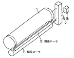
図5、図6中の搬送ローラ17は特開平6−214470で開示されたものであって、用紙搬送経路B上で、且つ、ドラム1と非接触状態で近接する位置に設けられている。この搬送ローラ17は下側ガイド部材14に案内されてドラム表面へ送られる用紙Pを該ドラム表面と接触する方向に強制搬送するために設けられたもので、具体的には下側ガイド部材14の傾斜上面とドラム表面との間で、該ドラム表面に可及的に近接する位置に配設されており、ドラム表面の周速度と等しい周速度で逆転駆動され、その周面上部が用紙Pの裏面に転接するように構成されている。また、この搬送ローラ17は導電性シリコンゴム等の比較的摩擦係数の大きい材料により形成されている。さらに、該搬送ローラ17は転写ローラ11と同程度の軸方向長さであることが必要である。また、ローラ径は用紙Pの搬送に支障がないものであれば、小径であるほどドラム表面に近接配置するのに好都合である。
【0021】
図6において、前記駆動系2は複写機各部の駆動源となる主モータ18と動力伝達系19とにより構成されている。即ち、本実施例においては、主モータ18の駆動力をギア列、クラッチ機構、リンク機構等からなる動力伝達系19を介してレジストローラ対9、ドラム1、転写ローラ11及び搬送ローラ17を含む各駆動部に必要な動力を伝達しており、且つ、該動力伝達系19においては、それぞれの駆動部の速度比、駆動方向、駆動タイミング等を相互に連関させてある。
【0022】
従って、本実施例では用紙Pが搬送経路B上をドラム表面の周速度と同一速度で移送されるように、レジストローラ対9及び搬送ローラ17をそれぞれドラム表面の周速度と同一周速度で、且つ、用紙Pをドラム側へ移動させる方向に回転駆動し、また、ドラム1を予め設定されたタイミングで駆動するように構成されている。
【0023】
上記構成の転写装置においては、レジストローラ対9がドラム1の回転に対応して用紙Pをドラム表面の周速度と等しい周速度で送り出すことにより、用紙Pが下側ガイド部材14に沿ってドラム側へ案内される。このとき用紙Pはドラム表面に接触する直前に搬送ローラ17の周面上部に接触し、該搬送ローラ17によって強制的にドラム側へドラム表面と等しい周速度で搬送され、さらにドラム表面に当接した後、ガイドテーブル15へ送られる。
【0024】
この場合、用紙Pはその裏面がドラム表面の直前位置で搬送ローラ17に転接し、これによって一定速度の搬送力が与えられて強制移送される。このとき該用紙Pは搬送ローラ17に裏面を支持されているため、先端部が自重により撓曲して下垂する間もなく、ほぼ搬送ローラ17との接線方向に移動し、直後に表面がドラム表面に当接することになる。従って、温度、湿度等の環境条件によって用紙Pの弾力性が変化するような場合にも、用紙Pは先端部が下垂してドラム表面から離れる間もなく、ドラム表面に静電気力により吸着される。
【0025】
しかも、ドラム表面に接触した状態では、該用紙Pは表裏面をドラム表面と搬送ローラ17の周面間に挟まれた形となるので、ドラム表面と同一周速度で逆方向に回転している搬送ローラ17からの駆動力を受けて一定の接触圧でもってドラム表面と位置ズレすることなく接触しながら搬送方向に移送されることになる。
【0026】
このようにして用紙Pがドラム表面と接触している間、転写ローラ11には電源12からドラム表面のトナー像とは逆極性の電圧が印加されており、これによって発生するクーロン力によりドラム表面に付着している帯電トナーが用紙Pの表面に転移する。従って、用紙P上の転写画像に画像むらが生じることが確実に防止される。
【0027】転写を終えた用紙Pはドラム表面から離れ、先端部がガイドテーブル26の上面に達した後、後端部がレジストローラ対9から離れ、その後はドラム1の回転に従ってガイドテーブル15上に沿って移送され、さらに用紙ガイド16を経て定着ローラ対10へ送られる。
【0028】
本実施例構成における各部の具体的寸法の一例を示す。この図に示すものでは、ドラム1の直径:30mm、転写ローラ本体11aの直径:14mm、転写ローラ本体11aの軸長:290mm、搬送ローラ17の直径6.5mmに寸法設定したものでは、ドラム表面と下側ガイド部材先端間の間隔:3mm、下側ガイド部材14の上面と転写ローラ11の周面間の間隔:2.2mmに設定している。また、下側ガイド部材14の上面と搬送ローラ17の周面間の空隙g:0.2〜1.0mmに設定している。
本機の、最大通紙サイズはA3(297×420mm)であり、プリントマージンを5mm設定することによって、通紙領域の最大幅は297mmであって、有効画像領域の最大幅は287mmである。転写ローラ本体11aの前端部、後端部を最大通紙領域の前後端から内側に各々3.5mmづつ離れた位置に配設している。黒比率6%の文字原稿を用いて、A4縦とA4横の比率を50:50として50枚おきに交互にプリント出力した結果5万枚プリント出力後も感光体表面の両端部付近の摩耗は見られず、トナー飛散も生ぜず、トナー消費量は25mg/枚のままで変動していなかった。比較例として、転写ローラ本体11aの軸長を305mmとして最大通紙領域の前後端から外側に各々4mmはみ出るように配設し、上記と同様のプリント出力を行った結果た結果、3万枚プリント出力では異状は認められなかったが、5万枚プリント出力時点では通紙領域から転写ローラ本体11aがはみ出た部位に相当する感光体表面の摩耗と現像部からのトナー飛散が認められトナー消費量が35mg/枚までアップしていた。
【0029】
尚、上記実施例においては転写ローラ方式において転写ローラと感光体の隙間寸法が転写シート厚さよりも大きく転写ローラが用紙及び感光体と非接触状態を保つ構成の画像形成装置について記載したが、これに限定されるものではなくて、ベルト転写方式を使用することが可能である。
【0030】
【発明の効果】
以上説明したように本発明の非接触転写装置は、反転現像方式の画像形成装置においてローラ、ベルト等の転写部材の軸方向前後端を、コピーマージンを考慮した有効画像領域と感光体上の最大サイズの通紙領域の間に配設させることによって、感光体ドラム両端部への転写電荷注入による感光体の表面電位低下を防止して、トナー飛散、機内汚れ、トナー消費量増大などの不具合を防止することができる。
【図面の簡単な説明】
【図1】ローラ転写方式を用いた転写装置の模式図
【図2】ベルト転写方式を用いた転写装置の模式図
【図3】従来方式のローラ転写方式における転写ローラと最大用紙幅の寸法、位置関係を示した図
【図4】本発明のローラ転写方式における転写ローラと最大用紙幅と最大の有効画像領域の寸法、位置関係を示した図
【図5】本発明における、画像形成装置の概要図
【図6】本発明における、感光体ドラムと転写ローラと搬送ローラと駆動源の立体的な位置関係を示した図
【符号の説明】
1 感光体ドラム
3 帯電手段9
4 露光手段
5 現像手段
6 転写手段
7 クリーニング手段
8 除電手段
9 レジストローラ対
10 定着ローラ
11 転写ローラ
B 用紙搬送経路
P 用紙[0001]
BACKGROUND OF THE INVENTION
The present invention relates to a transfer apparatus that is incorporated in an image forming apparatus such as an electronic copying machine, a printer, or a facsimile, and that transfers a toner image formed on the surface of a photosensitive drum built in the apparatus onto a sheet-like material such as transfer paper. Is.
[0002]
[Prior art]
Conventionally, as an apparatus for electrostatic transfer of a toner image formed on the surface of an electrostatic image carrier such as a photosensitive drum in an electrophotographic copying machine or the like, a corona discharger is used as means for supplying transfer charge to the photosensitive member side. In addition to the non-contact type corona transfer method used, a roller transfer method using a conductive roller and a belt transfer method are typical. Examples of the contact state between the roller member or belt member and the photosensitive drum include non-contact forms other than the contact state. Further, as the non-contact mode, those that come into contact with each other through the sheet material when passing paper and those that do not come into contact are used.
[0003]
FIG. 1 shows an example of a roller transfer device. Here, in the transfer device, a
[0004]
Next, FIG. 2 shows an example of a belt transfer device. A transfer conveyance belt 23 (hereinafter referred to as a transfer belt) stretched by a
[0005]
However, there are cases where problems such as toner scattering and toner consumption increase occur as image formation is repeated, cleaning inside the apparatus is required at an early stage, and the maintenance cycle must be shortened. While investigating this problem, the photosensitive layer in the non-sheet passing area located outside the maximum sheet passing width on the surface of the photosensitive member facing the transfer member such as the transfer roller or transfer belt is abnormally worn in the circumferential direction. Thus, it was found that white powder was scattered on the surface of the non-sheet passing portion of the photoreceptor just before passing through the cleaning portion. The mechanism of abnormal wear on the surface of the photoreceptor is considered as follows.
[0006]
As shown in FIG. 3, the front end portion and the rear end portion in the axial direction of the transfer roller are usually included on the boundary line between the maximum width sheet passing area and the non-sheet passing area of the photosensitive drum, or not from the boundary line. The roller shaft length and attachment position are set so as to slightly protrude toward the paper area side. In the reversal development method, since the transfer roller charge is opposite in polarity to the main charging polarity on the surface of the photoreceptor, the non-sheet passing portion that is directly exposed to the injected charge from the transfer roller is charged in the opposite polarity to the main charging potential. The If a large number of such image formations continue continuously, the main charge of the non-sheet passing portion after the main charge is performed becomes insufficient, the surface potential is lowered, and the development bias voltage is approached.
[0007]
The developer magnetic brush carried on the developing roller and supplied to the electrostatic latent image on the photoconductor is set to exceed the maximum width of the paper passing area due to insufficient brush formation at both ends in the axial direction of the developing roller. Therefore, the non-sheet passing portion is also rubbed. However, since the surface potential of the non-sheet-passing portion is reduced to a level equal to or lower than the developing bias voltage, the toner is forcibly developed, resulting in an increase in toner consumption.
[0008]
In addition, the toner adhering to the non-sheet-passing portion of the photoreceptor is directly exposed to the charge injected from the transfer roller, and the metal oxide such as silica, titanium oxide, magnetite, alumina used as an external additive on the toner surface is used. The object part powder is detached and firmly adheres to the surface of the photoreceptor. Since the metal fine powder has a polishing action, the surface of the photoreceptor is scraped when cleaning. Since the abnormally worn portion has lost charging capability, the surface potential due to main charging is zero or greatly reduced. Since the surface potential difference of the abnormally worn portion is much lower than the developing bias voltage, a large amount of toner is forcibly developed from the developer on the developing roller to the photosensitive member side, and the toner consumption increases or the toner scatters. Arise. The micro-cracks in the worn part tend to expand into the paper passing area, and as a result, the part where the charging ability is lost spreads even in the paper passing area. Or Such a defect occurs in either the roller transfer system or the belt transfer system, or when the transfer member and the photosensitive member are in contact or non-contact when the sheet is not passed, resulting in shortening the maintenance cycle. An early solution has been desired.
[0009]
[Problems to be solved by the invention]
Accordingly, in view of the above problems, a first object of the present invention is to extend the maintenance cycle of in-machine cleaning without causing problems such as image defects, toner scattering, and toner consumption increase.
Furthermore, a second object of the present invention is to extend the life of the photosensitive member without causing local wear.
[0010]
[Means for Solving the Problems]
According to a first aspect of the present invention, there is provided a non-contact transfer apparatus using a roller member or a belt member as a transfer member for transferring a toner image on the surface of an electrostatic image carrier to a sheet material. When viewed in the direction perpendicular to the paper passing direction, the front end and the rear end of the transfer area by the transfer member are the boundary between the effective image area having the maximum width of the opposing image carrier and the surrounding non-image area. It is arranged on the line or on the non-image area side, and is located on the boundary line between the maximum width sheet-passing area on the surface of the electrostatic image bearing member and the non-sheet-passing area outside or on the sheet-passing area side. It is arranged so that it may do.
According to a second aspect of the present invention, there is provided an image using the reversal developing type developing means for visualizing the electrostatic latent image on the image carrier with toner and the transfer device according to the first aspect. Forming device.
[0011]
According to the first and second aspects of the present invention, among the transfer charges having the opposite polarity to the main charge in the reversal development, the minute corona discharge due to the transfer charge from the non-contact transfer member to the region of the photoreceptor exceeding the maximum sheet size. Suppresses exposure and transfer charge injection. As a result, when image formation is repeated, it is possible to prevent the main charge of the non-sheet passing portion from becoming insufficient and the surface potential from being lowered to approach the developing bias voltage. The adhesion of the agent can be prevented. Furthermore, abnormal wear of the photosensitive layer of the photoreceptor due to adhesion of the toner external additive can be prevented. The maximum size (eg: A3 size) in the normal use mean that only the paper has name, for example, the width than the maximum width narrower sheet (eg: A4 size) in the case of also this region (A4 width It is possible to prevent adhesion of toner having a width greater than 210 mm and a width of A3 width smaller than 297 mm to the transfer material by using a non-contact transfer device. Also, in order to obtain the maximum effective image region of size on the transfer sheet of the maximum size, always small corona discharge from the end portion of the non-contact transfer member while preventing the exposed directly photoreceptor surface, the minimum Since a limited print margin can be ensured, image defects can be prevented.
[0012]
Here, the effective image area of the maximum width is the area of the transfer sheet of the transfer sheet of the maximum size to which the toner image of the maximum copy size is transferred, excluding the print margin width of the peripheral part. This is a portion excluding margins of 5 to 10 mm on the outer periphery of the size transfer sheet. The maximum width sheet passing area is the transfer sheet area having the maximum size. As is clear from FIG. 3, the conventional transfer roller exceeds the maximum width of the sheet passing area, whereas in the present invention, as shown in FIG. 4, the maximum effective image area exceeds the maximum width. The axial length and mounting position of the transfer roller are set so as to be equal to or less than the sheet passing area.
[0013]
DETAILED DESCRIPTION OF THE INVENTION
Embodiments of the present invention will be described below with reference to the drawings. FIG. 5 schematically shows an outline of one embodiment of the image forming apparatus of the present invention. This image forming apparatus uses a reversal developing system as a developing means and a roller transfer system as a transferring means, and the copying speed is 13 sheets / minute for A4 size. Reference numeral 1 denotes a photosensitive drum as an electrostatic image carrier, in which a photosensitive layer made of an organic photosensitive material is formed on the surface of a metal element tube such as aluminum. The photosensitive drum is rotationally driven by a driving unit (not shown) so as to be in the forward direction with the transfer direction of the transfer paper P in the transfer area. A charging unit 3, an
[0014]
In the copying machine having the above-described configuration, the surface photosensitive layer of the drum 1 is charged to +700 V by the charging means 3 by corona discharge. The charged drum surface is irradiated with light according to the original image read by the optical means (not shown) provided in the machine by the exposure means 4 having a laser source, and the photosensitive drum surface is not exposed. An electrostatic line image composed of + 700V of the portion and + 120V of the exposed portion is formed. Charged toner is attached to the electrostatic latent image by developing means to form a toner image. The developing means 5 stores a developer that is a mixture of 95 parts by weight of a magnetic carrier having an average particle diameter of 90 μm and five parts of a positively chargeable toner having an average particle diameter of 9 μm. Since the developing bias is applied, the positively chargeable toner is developed with respect to the exposed portion, and a toner image is formed on the surface of the photoreceptor. On the surface of the positively chargeable toner, 0.2 parts by weight of titanium oxide and silica for improving fluidity and chargeability (each 100 parts by weight of toner) are dispersed and adhered.
[0015]
When the toner image formed on the surface of the photosensitive drum rotates and moves to a position facing the transfer unit 6, the toner image is exposed on the surface of the transfer sheet P conveyed in synchronization with the toner image by the
[0016]
The transfer roller 11 included in the transfer unit 6 is disposed below the drum 1 and in parallel with the drum shaft at a position facing the surface of the drum 1 with a gap larger than the thickness of the paper P across the paper transport path B. Has been. The transfer roller 11 is rotationally driven in the forward direction with the opposing drum surface, and its rotational peripheral speed is substantially the same as the rotational peripheral speed of the drum. It is important that the gap is set to be larger than the thickness of the transfer sheet P. In general, the gap is preferably about 0.2 to 2.0 mm. The transfer roller 11 is configured to transfer the charged toner attached to the drum surface to the paper P by applying a voltage having a polarity opposite to that of the charged toner attached to the drum surface at the time of transfer.
[0017]
With reference to FIGS. 4 and 5, the axial length of the transfer roller of the present invention and the attachment positions of the front end portion and the rear end portion will be described in detail. The transfer roller 11 is formed in the shape of a long-axis roller formed by integrally fixing at least the roller body 11a around the rotation shaft 11b. The transfer roller body 11a has a length in the axial direction equal to or greater than the axial length of the effective image area 1a on which the toner image on the drum surface is formed, and the photosensitive member shaft of the maximum size transfer sheet to be used. The length must be equal to or less than the length of the direction. Further, the front and rear end portions of the transfer roller main body 11a in the axial direction are on the boundary line between the effective image area and the non-image area outside in the axial direction of the opposing photoconductor, or the non-image outside in the axial direction beyond the boundary line. It is necessary to be disposed so as to be located in the region. Further, the front and rear end portions of the transfer roller main body 11a in the axial direction are positioned on the boundary line between the sheet passing area and the axial non-passing area on the photosensitive member surface of the transfer sheet having the maximum size, or the shaft extends beyond the boundary line. In order to achieve the object of the present invention, it is essential to be disposed so as to be in the sheet passing region inside in the direction. With the above configuration, when trying to obtain the maximum size effective image area on the maximum size transfer sheet, the micro corona discharge is always prevented from directly exposing the photoreceptor surface from the end of the non-contact transfer roller. Since a minimum print margin can be ensured, image defects can be prevented. Even if small-size transfer sheets are mixed and used to increase the direct exposure of corona discharge from the non-contact transfer roller to the surface of the photoconductor, the transfer sheet of the maximum size is used only occasionally. The effect of the present invention can be obtained because the surface potential in the vicinity of the roller end can be prevented from being lowered.
[0018]
The roller body 11a of the transfer roller 11 can be formed of, for example, a conductive resin material such as polystyrene resin or urethane resin in which carbon or alkali metal is dispersed and mixed, a conductive rubber material, or the like. A
[0019]
Between the
[0020]
The
[0021]
In FIG. 6, the drive system 2 is constituted by a
[0022]
Therefore, in this embodiment, the
[0023]
In the transfer device configured as described above, the
[0024]
In this case, the back surface of the paper P is brought into contact with the
[0025]
In addition, in a state where the sheet P is in contact with the drum surface, the sheet P is sandwiched between the drum surface and the peripheral surface of the conveying
[0026]
While the paper P is in contact with the drum surface in this way, a voltage having a polarity opposite to that of the toner image on the drum surface is applied to the transfer roller 11 from the
After the transfer, the sheet P is separated from the drum surface, the leading end reaches the upper surface of the guide table 26, the rear end is separated from the
[0028]
An example of the specific dimension of each part in a present Example structure is shown. In the figure, the drum 1 has a diameter of 30 mm, the transfer roller body 11a has a diameter of 14 mm, the transfer roller body 11a has an axial length of 290 mm, and the
The maximum sheet passing size of this machine is A3 (297 × 420 mm). By setting the print margin to 5 mm, the maximum width of the sheet passing area is 297 mm and the maximum width of the effective image area is 287 mm. The front end portion and the rear end portion of the transfer roller main body 11a are disposed at positions 3.5 mm apart from the front and rear ends of the maximum sheet passing area. Using a text document with a black ratio of 6%, the ratio of A4 portrait and A4 landscape was set to 50:50, and the prints were alternately printed every 50 sheets. No toner scattering occurred, and the toner consumption was 25 mg / sheet and remained unchanged. As a comparative example, the axial length of the transfer roller main body 11a is set to 305 mm, and it is arranged so as to protrude 4 mm outward from the front and rear ends of the maximum sheet passing area. No abnormalities were observed in the output, but at the time of printing 50,000 sheets, the wear of the surface of the photosensitive member corresponding to the portion where the transfer roller main body 11a protruded from the paper passing area and the scattering of toner from the developing portion were recognized, and the toner consumption amount Was up to 35 mg / sheet.
[0029]
In the above-described embodiment, the image forming apparatus has been described in which the gap between the transfer roller and the photoconductor is larger than the transfer sheet thickness in the transfer roller system, and the transfer roller is kept in contact with the paper and the photoconductor. However, the belt transfer method can be used.
[0030]
【The invention's effect】
As described above, the non-contact transfer apparatus according to the present invention is a reversal development type image forming apparatus in which the front and rear ends in the axial direction of transfer members such as rollers and belts are arranged with an effective image area in consideration of a copy margin and a maximum on the photoreceptor. By disposing it between the paper passing areas of the size, the surface potential of the photoconductor is prevented from lowering due to transfer charge injection to both ends of the photoconductor drum, and problems such as toner scattering, internal contamination, and increased toner consumption are prevented. Can be prevented.
[Brief description of the drawings]
FIG. 1 is a schematic diagram of a transfer device using a roller transfer method. FIG. 2 is a schematic diagram of a transfer device using a belt transfer method. FIG. 3 is a diagram showing dimensions of a transfer roller and a maximum paper width in a conventional roller transfer method. FIG. 4 is a diagram showing the positional relationship. FIG. 4 is a diagram showing the size and positional relationship of the transfer roller, the maximum sheet width, and the maximum effective image area in the roller transfer system of the present invention. FIG. 6 is a diagram showing a three-dimensional positional relationship among a photosensitive drum, a transfer roller, a transport roller, and a drive source in the present invention.
1 Photosensitive drum 3 Charging means 9
4 Exposure means 5 Development means 6 Transfer means 7 Cleaning means 8 Static elimination means 9
Claims (2)
シート材の通紙方向に対して垂直方向にみた場合の、前記転写部材による転写領域の前端部と後端部が、対向する像担持体の最大幅の有効画像領域とその周囲の非画像領域との境界線上あるいは非画像領域側に位置するように配設されるとともに、静電像担持体表面の最大幅の通紙領域とその外側の非通紙領域との境界線上あるいは、通紙領域側に位置するように配設されていることを特徴とする転写装置。A non-contact transfer device using a roller member or a belt member as a transfer member for transferring a toner image on the surface of an electrostatic image carrier to a sheet material,
When viewed in a direction perpendicular to the sheet passing direction of the sheet material, the front end portion and the rear end portion of the transfer region by the transfer member are the effective image region having the maximum width of the opposing image carrier and the surrounding non-image region. Is located on the boundary line or on the non-image area side, and is on the boundary line between the maximum width sheet passing area on the surface of the electrostatic image carrier and the non-sheet passing area outside or on the sheet passing area. A transfer device, wherein the transfer device is disposed so as to be positioned on the side.
Priority Applications (1)
| Application Number | Priority Date | Filing Date | Title |
|---|---|---|---|
| JP2001260674A JP3684342B2 (en) | 2001-08-30 | 2001-08-30 | Transfer device and image forming apparatus using the same |
Applications Claiming Priority (1)
| Application Number | Priority Date | Filing Date | Title |
|---|---|---|---|
| JP2001260674A JP3684342B2 (en) | 2001-08-30 | 2001-08-30 | Transfer device and image forming apparatus using the same |
Publications (2)
| Publication Number | Publication Date |
|---|---|
| JP2003066741A JP2003066741A (en) | 2003-03-05 |
| JP3684342B2 true JP3684342B2 (en) | 2005-08-17 |
Family
ID=19087841
Family Applications (1)
| Application Number | Title | Priority Date | Filing Date |
|---|---|---|---|
| JP2001260674A Expired - Fee Related JP3684342B2 (en) | 2001-08-30 | 2001-08-30 | Transfer device and image forming apparatus using the same |
Country Status (1)
| Country | Link |
|---|---|
| JP (1) | JP3684342B2 (en) |
-
2001
- 2001-08-30 JP JP2001260674A patent/JP3684342B2/en not_active Expired - Fee Related
Also Published As
| Publication number | Publication date |
|---|---|
| JP2003066741A (en) | 2003-03-05 |
Similar Documents
| Publication | Publication Date | Title |
|---|---|---|
| JP2002089547A (en) | Roller device | |
| JP4336353B2 (en) | Developing device and image forming apparatus | |
| JP2009109569A (en) | Image forming apparatus and cleaning method of photoreceptor | |
| JP2022059719A (en) | Image forming apparatus | |
| JP3768931B2 (en) | Image forming apparatus | |
| JP2008003110A (en) | Charger, process cartridge, and image forming apparatus | |
| US20220107585A1 (en) | Image forming apparatus | |
| JP3684342B2 (en) | Transfer device and image forming apparatus using the same | |
| KR100196572B1 (en) | Method and apparatus of decneasing opposite transcription for electrophotogra phic tmage forming apparatus | |
| JP5170690B2 (en) | Image forming apparatus | |
| JP2004046215A (en) | Developing device and electrophotographic device | |
| JPH04138484A (en) | Image forming device | |
| JP2022059720A (en) | Image forming apparatus | |
| JP2000131973A (en) | Image forming device | |
| KR100529348B1 (en) | Developing apparatus and electrophotographic image forming apparatus adopting the same | |
| JP2001142366A (en) | Image forming device and its cleaning method | |
| JP2001343844A (en) | Transfer device | |
| JP2004126104A (en) | Image forming apparatus | |
| JP2000347534A (en) | Image forming device | |
| JP5530964B2 (en) | Developing device and image forming apparatus | |
| JP2006267549A (en) | Image forming apparatus | |
| JPH01277269A (en) | Image forming device | |
| JP2005258044A (en) | Cleaning device and image recorder | |
| JP2021117241A (en) | Image forming apparatus | |
| JP3597273B2 (en) | Image forming device |
Legal Events
| Date | Code | Title | Description |
|---|---|---|---|
| A131 | Notification of reasons for refusal |
Free format text: JAPANESE INTERMEDIATE CODE: A131 Effective date: 20050207 |
|
| A521 | Written amendment |
Free format text: JAPANESE INTERMEDIATE CODE: A523 Effective date: 20050408 |
|
| TRDD | Decision of grant or rejection written | ||
| A01 | Written decision to grant a patent or to grant a registration (utility model) |
Free format text: JAPANESE INTERMEDIATE CODE: A01 Effective date: 20050519 |
|
| A61 | First payment of annual fees (during grant procedure) |
Free format text: JAPANESE INTERMEDIATE CODE: A61 Effective date: 20050530 |
|
| R150 | Certificate of patent or registration of utility model |
Free format text: JAPANESE INTERMEDIATE CODE: R150 |
|
| FPAY | Renewal fee payment (event date is renewal date of database) |
Free format text: PAYMENT UNTIL: 20090603 Year of fee payment: 4 |
|
| FPAY | Renewal fee payment (event date is renewal date of database) |
Free format text: PAYMENT UNTIL: 20100603 Year of fee payment: 5 |
|
| FPAY | Renewal fee payment (event date is renewal date of database) |
Free format text: PAYMENT UNTIL: 20110603 Year of fee payment: 6 |
|
| FPAY | Renewal fee payment (event date is renewal date of database) |
Free format text: PAYMENT UNTIL: 20110603 Year of fee payment: 6 |
|
| FPAY | Renewal fee payment (event date is renewal date of database) |
Free format text: PAYMENT UNTIL: 20120603 Year of fee payment: 7 |
|
| FPAY | Renewal fee payment (event date is renewal date of database) |
Free format text: PAYMENT UNTIL: 20120603 Year of fee payment: 7 |
|
| S533 | Written request for registration of change of name |
Free format text: JAPANESE INTERMEDIATE CODE: R313533 |
|
| R350 | Written notification of registration of transfer |
Free format text: JAPANESE INTERMEDIATE CODE: R350 |
|
| FPAY | Renewal fee payment (event date is renewal date of database) |
Free format text: PAYMENT UNTIL: 20120603 Year of fee payment: 7 |
|
| FPAY | Renewal fee payment (event date is renewal date of database) |
Free format text: PAYMENT UNTIL: 20130603 Year of fee payment: 8 |
|
| FPAY | Renewal fee payment (event date is renewal date of database) |
Free format text: PAYMENT UNTIL: 20140603 Year of fee payment: 9 |
|
| LAPS | Cancellation because of no payment of annual fees |