JP3682003B2 - L-type rotary coaxial connector plug - Google Patents
L-type rotary coaxial connector plug Download PDFInfo
- Publication number
- JP3682003B2 JP3682003B2 JP2001233832A JP2001233832A JP3682003B2 JP 3682003 B2 JP3682003 B2 JP 3682003B2 JP 2001233832 A JP2001233832 A JP 2001233832A JP 2001233832 A JP2001233832 A JP 2001233832A JP 3682003 B2 JP3682003 B2 JP 3682003B2
- Authority
- JP
- Japan
- Prior art keywords
- plug
- connector
- coaxial connector
- rotary
- shaped
- Prior art date
- Legal status (The legal status is an assumption and is not a legal conclusion. Google has not performed a legal analysis and makes no representation as to the accuracy of the status listed.)
- Expired - Fee Related
Links
Images


Description
【0001】
【発明の属する技術分野】
本発明は、本体の一方にコネクタ部が備えられ、他方にプラグ部が備えられたL字状の形状とされたL型回転同軸コネクタプラグに関するものである。
【0002】
【従来の技術】
従来、通信機器やCATV機器等においては、ラックに各回路が収納され、ラックの前面には各回路のパネルが設けられている。このような機器において、各回路同士を接続する際には、パネルに設けられている同軸コネクタに同軸ケーブルの一側の先端に設けられた同軸プラグを接続すると共に、同軸ケーブルの他側に設けられた同軸プラグを接続したい回路のパネルに設けられた同軸コネクタに接続するようにしている。この場合、接続する2つの同軸コネクタが近接配置されている際には、同軸ケーブルをU字状に折り曲げて接続することになるが、このように同軸ケーブルをU字状に折り曲げると高周波特性が劣化することがあった。
【0003】
そこで、これに替える手段としてL型同軸コネクタプラグを用いて、同軸ケーブルをほぼパネルに並行になるよう配置することが行われていた。L型同軸コネクタプラグは、一端にコネクタ部が設けられ、他端にプラグ部が設けられ全体がL字状の形状とされている。このため、L型同軸コネクタプラグでは、本体内部においてプラグ部における中心導体とコネクタ部における中心コンタクトとが直交して配置される必要があり、L型同軸コネクタプラグ内において中心導体と中心コンタクトとを接続する作業が繁雑な作業になると共に、L型同軸コネクタプラグ自体の構成が複雑になっていた。
【0004】
そこで、本出願人は中心導体と中心コンタクトとを接続する作業を簡易化することのできるL型同軸コネクタプラグを、特願2000−117545号として提案している。
このL型同軸コネクタプラグにおいては、中心導体と中心コンタクトとを接続する作業を簡易化することができるという従来なし得なかった作用を奏することができる。しかし、プラグ部を外部の同軸コネクタに螺着した際に、同軸コネクタの先端がプラグ部内に圧接されるようになる。これにより、圧接されたプラグと同軸コネクタの先端との間の摩擦力により、L型同軸コネクタプラグは取り付けられた同軸コネクタに対して回転できないようになる。したがって、L型同軸コネクタプラグにおけるコネクタ部に接続されている同軸ケーブルに捻れ等により応力が発生した際に、その応力が同軸ケーブルに印加されたままとなり、同軸ケーブルに悪影響を与えたり、L型同軸コネクタプラグや同軸コネクタの破損や緩みの原因になってしまっていた。
また、L型同軸コネクタプラグにおけるプラグ部に緩みが発生すると同軸コネクタとのアースの接続が不完全となり、L型同軸コネクタプラグの挿入損失特性および反射損失特性が劣化し、信号の授受に支障を与えるようになっていた。
【0005】
【発明が解決しようとする課題】
そこで、本出願人は、取付状態においてコネクタ部がプラグ部に対して回転することのできるL型回転同軸コネクタプラグを特願2000−255042号として提案している。
このL型回転同軸コネクタプラグは、取付状態においてコネクタ部がプラグ部に対して回転することができるという画期的な作用を奏することができる。しかし、L型回転同軸コネクタプラグが取り付けられる同軸コネクタの先端形状が特殊な形状をしていた場合には、取付状態においてコネクタ部がプラグ部に対して回転することができない場合が生じるおそれがあった。さらに、同軸コネクタが特殊な作用を有するための構造を有している場合には、L型回転同軸コネクタプラグが取り付けられた際に、その特殊な作用を奏さないおそれがある場合があった。
【0006】
以下に、この問題点について図12ないし図15を参照しながら説明する。
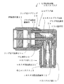
図12には、L型回転同軸コネクタプラグ100が同軸コネクタ150に取り付けられている状態が断面図で示されている。この図に示すようにL字状に形成されたコネクタプラグ本体102の一方にコネクタ部110が備えられ、他方にプラグ部120が備えられている。コネクタ部110は、コネクタプラグ本体102における断面が略円筒状とされたコネクタ用収納室102b内に嵌着された絶縁性のコネクタ用筒状絶縁体112を備えている。このコネクタ用筒状絶縁体112は中心コンタクト113を保持しており、これによりコネクタ用収納室102bの略中心軸上に中心コンタクト113が配置されるようになされている。また、プラグ部120は断面が略円筒状とされていると共に、コネクタ用収納室102bと略直交して配置されたコネクタプラグ本体102におけるプラグ用収納室102a内に絶縁性のプラグ用筒状絶縁体123が嵌着されている。このプラグ用筒状絶縁体123は中心導体122を保持しており、これによりプラグ用収納室102aの略中心軸上に中心導体122が配置されるようになる。
【0007】
この中心導体122の後端は、中心コンタクト113の後端に形成されている抱持部113d内に挿着されて、中心導体122と中心コンタクト113とは電気的に接続されている。コネクタプラグ本体102の一端部にはリング状スプリング124が介在されて回転取付体121が取り付けられている。この場合、コネクタプラグ本体102の先端部が拡径されるようにカール加工されて、回転取付体121の内周面に形成されているリング状回転係合部に回転可能に係合されるようになる。これにより、コネクタプラグ本体102の一端部に回転可能に回転取付体121が固着されるようになる。回転取付体121の内周面には、リング状回転係合部より先端側に停止用リング状突起121eが形成されている。
【0008】
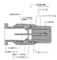
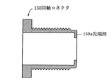
このような構成のL型回転同軸コネクタプラグ100を、図13に示すような同軸コネクタ150に螺着すると、L型回転同軸コネクタプラグ100の停止用リング状突起121eに同軸コネクタ150の先端部150aが衝合した際に、同軸コネクタ150にL型回転同軸コネクタプラグ100が取り付けられるようになる。この場合、取付状態において同軸コネクタ150の先端部150aとプラグ用筒状絶縁体123との間には間隙が生じるようになることから、L型回転同軸コネクタプラグ100が同軸コネクタ150に取り付けられた状態において、コネクタプラグ本体102が回転取付体121に対して回転可能となる。
ところが、このようなL型回転同軸コネクタプラグ100が、図14に示すように先端テーパ部160aが長く形成され、その先端における径がすぼまっている特殊な形状の同軸コネクタ160に取り付けられると図12に示す状態となってしまう。この場合には、同軸コネクタ160の先端テーパ部160aの先端の径がすぼまっているために、図示するようにその先端テーパ部160aが停止用リング状突起121eを超えてプラグ用筒状絶縁体123の先端面に衝合するようになる。すると、先端テーパ部160aとプラグ用筒状絶縁体123の先端面との間の摩擦により、取付状態においてはコネクタプラグ本体102は回転取付体121に対して回転できないようになってしまうことになる。
【0009】
これを防止するには、プラグ用筒状絶縁体123の前面を図示する場合より後方に後退すればよいと考えられる。しかし、プラグ用筒状絶縁体123の前面を後方に後退させると、特許第2978144号にかかる図15(a)に示すようなダミー内蔵同軸コネクタ200にL型回転同軸コネクタプラグ100を取り付けた際に、ダミーで終端されたままになってしまうようになる。この理由をダミー内蔵同軸コネクタ200の動作を簡単に説明することにより述べる。ダミー内蔵同軸コネクタ200にL型回転同軸コネクタプラグ100を取り付けると、L型回転同軸コネクタプラグ100の停止用リング状突起121eにダミー内蔵同軸コネクタ200における本体部210の先端が衝合する。
【0010】
この際に、可動絶縁体211がプラグ用筒状絶縁体123の先端面に当接すれば弾性体214の弾力に抗して本体部210内に押し込まれ、図17(b)に示すようにスイッチ基板213が後方に移動するようになる。すると、スイッチ基板213と本体部210との電気的接続が絶たれて、スイッチ基板213に組み込まれたダミーによる終端が解除されるようになる。ところが、プラグ用筒状絶縁体123の前面を後方に後退させると、L型回転同軸コネクタプラグ100の停止用リング状突起121eにダミー内蔵同軸コネクタ200における本体部210の先端が衝合した際に、可動絶縁体211の先端面がプラグ用筒状絶縁体123の先端面に届かず、可動絶縁体211が図17に示すように後方に移動しないおそれが生じるようになる。この場合は、ダミー内蔵同軸コネクタ200はダミーにより終端され続けることになり、ダミー内蔵同軸コネクタ200において信号が減衰してしまうようになる。
【0011】
そこで、本発明は、特殊な先端形状の同軸コネクタでも取付状態においてコネクタ部がプラグ部に対して回転することができると共に、特殊な作用を有する構造の同軸コネクタに取り付けた際にその作用を奏することのできるL型回転同軸コネクタプラグを提供することを目的としている。
【0012】
【課題を解決するための手段】
上記目的を達成するために、L字状に形成された本体の一方にコネクタ部が備えられ、他方にプラグ部が備えられたL型同軸コネクタプラグであって、前記コネクタ部は、前記本体における断面が略円筒状とされたコネクタ用収納室内に嵌着された絶縁性のコネクタ用筒状絶縁体と、該コネクタ用筒状絶縁体で保持されることにより、前記コネクタ用収納室の略中心軸上に配置された中心コンタクトとからなり、前記プラグ部は、断面が略円筒状とされていると共に、前記コネクタ用収納室と略直交して配置された前記本体におけるプラグ用収納室内に嵌着された絶縁性のプラグ用筒状絶縁体と、該プラグ用筒状絶縁体で保持されることにより、前記プラグ用収納室の略中心軸上に配置されて、後端が前記中心コンタクトの後端に形成された抱持部に嵌入されて電気的に接続されている中心導体と、前記本体の他方における端部に回転可能に固着されていると共に、外部の同軸コネクタに固着可能とされている回転取付体と、前記中心導体に接触しないように所定の高さでほぼ垂直に前記回転取付体の内周面に立設されているリング状立設部とからなり、前記回転取付体を外部の同軸コネクタに取り付けた際に、該同軸コネクタの先端が前記リング状立設部の前面に衝合することにより、前記本体が前記回転取付体に対して回転可能とされている。
【0013】
また、上記本発明のL型回転同軸コネクタプラグにおいて、前記本体の先端縁が拡径されるように加工されることにより、前記先端縁が前記回転取付体の内周面に形成されている回転係合部に回転可能に係合されて、前記回転取付体が前記本体に対して回転可能に固着されており、前記回転取付体の内周面と前記本体の先端部における嵌合筒状部の外周面との間にリング状スプリングが介在されていてもよい。
さらに、本発明のL型回転同軸コネクタプラグにおいて、前記リング状スプリングは、前記回転取付体の内周面に形成されたスプリング収納部の溝内から抜け出ないように収納されていてもよい。
【0014】
このような本発明によれば、プラグ部における回転取付体を外部の同軸コネクタに取り付けた際に、同軸コネクタの先端が回転取付体の内周面に形成されているリング状立設部に衝合するようになる。これにより、同軸コネクタの先端の径が細くされている図14に示すような同軸コネクタであっても、取付状態においてコネクタ部をプラグ部に対して回転可能とすることができる。また、同軸コネクタが図15に示すような構造を有していても、可動絶縁体はリング状立設部により確実に押し込められるようになるので、その作用を確実に奏することができるようになる。
【0015】
この結果、L型回転同軸コネクタプラグにおけるコネクタ部に接続されている同軸ケーブルに応力が発生してもその応力は、本体と共に同軸ケーブルが回転することにより取り除かれ、同軸ケーブルに悪影響が残らないようになる。さらに、応力が取り除かれるためL型回転同軸コネクタプラグが緩むことを防止することができるようになる。また、このようにL型回転同軸コネクタプラグを取り付けた状態において本体が回転可能に構成されていても、回転取付体内に収納されたリング状スプリングにより確実なアース接続を行うことができるため、L型回転同軸コネクタプラグの電気的特性が劣化することはない。
【0016】
【発明の実施の形態】
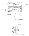
本発明の実施の形態にかかるL型回転同軸コネクタプラグ全体の構成を図1に示す。ただし、図1(a)は本発明にかかるL型回転同軸コネクタプラグの平面図であり、図1(b)はその正面図であり、図1(c)はその底面図である。
図1(a)(b)(c)に示すように本発明にかかるL型回転同軸コネクタプラグ1は、導電性の例えば金属製とされたL字状のコネクタプラグ本体2からなり、その一端がプラグ部20とされ、プラグ部20にほぼ直交する他端部にコネクタ部10が形成されている。このコネクタ部10は、外周にネジが形成された円筒状のコネクタネジ部11を備えており、このコネクタネジ部11内には図1(c)に示すように、同軸状に中心コンタクト13と、中心コンタクト13を保持するコネクタ用筒状絶縁体12とが収納配置されている。また、プラグ部20は外形が六角形とされた回転取付体21と、図1(b)に示すように回転取付体21に略同軸に配置された中心導体22と、中心導体22を保持する後述するプラグ用筒状絶縁体23とが収納配置されている。プラグ用筒状絶縁体23の前面に位置して、図1(b)に示すようにリング状立設部21cが回転取付体21の内周面からほぼ垂直に立設されている。この回転取付体21は、コネクタプラグ本体2に回転可能に固着されており、パネル等に設けられた同軸コネクタに螺着される部分である。
【0017】
このような本発明にかかるL型回転同軸コネクタプラグ1の詳細な構成を、図2に示す分解組み立て図、図3ないし図5に示すL型回転同軸コネクタプラグ1の構成を示す断面図、および、図6ないし図11に示す部品図を参照しながら以下に説明する。ただし、図3は本発明にかかるL型回転同軸コネクタプラグの構成を断面図で表した平面図であり、図4は本発明にかかるL型回転同軸コネクタプラグを特殊な機能を有する同軸コネクタに取り付けた状態を断面図で表した平面図であり、図5は本発明にかかるL型回転同軸コネクタプラグを特殊な先端形状の同軸コネクタに取り付けた状態を断面図で表した上面図であり、図6は中心コンタクトを保持するコネクタ用筒状絶縁体12の構成を示す図であり、図7はコネクタプラグ本体2の構成を示す図であり、図8は回転取付体21の構成を示す図であり、図9はプラグ用筒状絶縁体23の構成を示す図であり、図10は中心導体22の構成を示す図であり、図11は中心コンタクト13の構成を示す図である。
【0018】
まず、本発明の実施の形態に係るL型回転同軸コネクタプラグ1の組立方法を説明する。
コネクタプラグ本体2は、図2および図7に示すようにL字状にダイキャスト等により作成されている。L型回転同軸コネクタプラグ1を組み立てる際には、まず、このL型のコネクタプラグ本体2の一端に形成されているプラグ用収納室2a内に、プラグ用筒状絶縁体23を嵌着する。この際に、図9(c)に示すように合成樹脂製とされたプラグ用筒状絶縁体23の後部は上下がカットされて上下対称に構成されており、プラグ用収納室2aの断面形状が図7(b)(d)に示すように中途からD字状、奥はプラグ用筒状絶縁体23の後部と同様の形状とされているので、プラグ用筒状絶縁体23はプラグ用収納室2aに対して位置決めされて嵌着されるようになる。このように、プラグ用筒状絶縁体23をプラグ用収納室2aに対して位置決めするのは、図9(a)(b)(e)に示すようにプラグ用筒状絶縁体23の後部23cに、中心コンタクト13の後端に形成されている抱持部13dが収納される抱持部収納部23dが形成されているからである。
【0019】
ついで、図2に示すようにコネクタプラグ本体2の他端にほぼ直交して形成されたコネクタネジ部11におけるコネクタ用収納室2b内に、中心コンタクト13をほぼ中心軸に沿って保持した状態の合成樹脂製とされたコネクタ用筒状絶縁体12を嵌着する。この場合、図7(c)(d)に示すようにコネクタ用収納室2b内の奥には三角状に突出する三角突部2eが対向して2つ形成されており、この三角突部2eの斜辺の壁に沿って案内される第1突部12eおよび第2突部12dが、図6(a)に示すようにコネクタ用筒状絶縁体12における筒状部本体12aの後端部に形成されている。このため、コネクタ用筒状絶縁体12はコネクタ用収納室2bに対して所定の角度で位置決めされて嵌着されるようになる。このように、コネクタ用筒状絶縁体12をコネクタ用収納室2bに対して位置決めするのは、コネクタ用筒状絶縁体12に保持されている中心コンタクト13の抱持部13dをコネクタプラグ本体2内に所定の角度で配置するためである。
【0020】
このようにして、コネクタ用収納室2b内にコネクタ用筒状絶縁体12を嵌着すると、コネクタ用筒状絶縁体12の後端部に形成された第1突部12eおよび第2突部12dにより、コネクタ用収納室2bの奥に形成されたリング状の突部を、図3および図4に示すように挟持するようになる。さらに、コネクタ用筒状絶縁体12における第1突部12eが形成されている後端部が、プラグ用筒状絶縁体23の後部23cに嵌入されるようになる。これにより、図3および図4に示すようにコネクタ用筒状絶縁体12がコネクタ用収納室2b内から抜け出せないように嵌着されると共に、プラグ用筒状絶縁体23もプラグ用収納室2a内から抜け出せないように嵌着されることになる。さらに、コネクタ用筒状絶縁体12の貫通孔12c内に保持されている中心コンタクト13における抱持部13dが予め定められた所定の向きになるように配置されることになる。また、コネクタ用筒状絶縁体12における筒状部本体12aの前端には環状突部12bが形成されており、この環状突部12bの外周縁がコネクタ用収納室2bの内周面に当接することにより、貫通孔12c内に保持されている中心コンタクト13がコネクタ用収納室2bのほぼ中心軸上に配置されると共に、コネクタ用収納室2bは閉塞されるようになる。
【0021】
ここで、中心コンタクト13について図11を参照しながら説明する。コネクタ部10に同軸ケーブルの先端に設けられた同軸プラグが取り付けられた際に、中心コンタクト13には当該同軸プラグの中心導体が挿入されて両者の電気的接続が行われるようにされている。中心コンタクト13は金属板を加工して作成されており、図11(e)に示すように断面が例えば6角形の内の5辺からなるコンタクト基部13aと、コンタクト基部13aから前方へ延伸する挟持部13bと、コンタクト基部13aから後方へ延伸する延伸部13cから構成されている。また、延伸部13cの先端には中心コンタクト13の中心軸とほぼ直交する方向にプラグ部20における中心導体22を弾性的に保持する抱持部13dが形成されている。挟持部13bは図11(g)に示されているように断面がくの字状に折曲されて十分な挟持力を有するようにされており、その先端は拡開されて同軸プラグの中心導体を挿入しやすくされている。さらに、挟持部13bはその構造上、ある程度径の異なる中心導体であっても挟持して電気的接続を確実に行うことができる。また、抱持部13dには縦方向にスリットが全体にわたり形成されており、これにより抱持部13dは弾性を持って中心導体22を確実に抱持することができるようにされている。
【0022】
このような中心コンタクト13が、コネクタ用筒状絶縁体12により保持されてコネクタ用収納室2b内に収納されると、その抱持部13dがプラグ用収納室2a内に収納されたプラグ用筒状絶縁体23の抱持部収納部23dに位置するようになる。この際に、抱持部13dは予め定められた向きになるように配置され、この状態において図2に示すように中心導体22をプラグ用筒状絶縁体23に挿通する。中心導体22は、図2の拡大図および図10に示すように、細長い棒状とされており、金メッキ等された金属製とされている。中心導体22のほぼ半ばまでには中心導体部22aが形成され、この中心導体部22aに連接して径が太くされた嵌合部22cが形成されており、嵌合部22cの中途にはテーパ部22bが形成されている。さらに、嵌合部22cは延伸されて若干径が細くされた接続部22dが形成されている。また、図9に示すようにプラグ用筒状絶縁体23の円筒状の筒状前部23bには、ほぼ中央に嵌挿孔23aが形成されており、この嵌挿孔23aは後部23cに形成された抱持部収納部23dまで連通している。すなわち、中心導体22をプラグ用筒状絶縁体23の嵌挿孔23aに挿通していくと、テーパ部22bが形成されている中心導体22の嵌合部22cがプラグ用筒状絶縁体23に形成された嵌挿孔23aに挿通されるようになる。さらに、挿通していくと中心導体22の接続部22dが抱持部収納部23dに達して、抱持部収納部23dに位置している抱持部13d内に嵌入されるようになる。
【0023】
そして、接続部22dの先端が、図9(e)に示すプラグ用筒状絶縁体23における後面壁部23eに形成された保持穴内に図3に示すように挿入されるまで、中心導体22は嵌挿孔23a内に挿入されていく。この場合、嵌合部22cに形成されているテーパ部22bの作用により、中心導体22は嵌挿孔23aから抜け出ないように確実に係合されるようになる。また、中心コンタクト13における抱持部13dには、図11(b)(c)に示すようにスリットが形成されて弾性を有するようにされているので、抱持部13dに挿入された接続部22dとは確実に電気的に接続されるようになる。これによりコネクタ部10が構成され、中心導体22における接続部22dが、中心コンタクト13における抱持部13dに電気的に接続されるため、ほぼ直交配置された中心導体22と中心コンタクト13とが電気的に接続されるようになる。このように、本発明にかかるL型回転同軸コネクタプラグ1においては、ほぼ直交配置された中心導体22と中心コンタクト13との接続を簡単な作業により行うことができる。
【0024】
ついで、コネクタプラグ本体2におけるプラグ用収納室2aの外周に形成された嵌合筒状部2dに回転取付体21を取り付けるのであるが、回転取付体21の外形は六角ナットと同様に六角形とされており、金属製とされている。回転取付体21は、図8(b)に示すように、回転取付体21の内周面の前部に外部の同軸コネクタに螺着する取付ネジ部21dが切られている。また、回転取付体21の内周面の後部にはリング状スプリング24が収納されるスプリング収納部21aが形成されており、内周面の取付ネジ部21dの後にリング状に立設している所定高さとされたリング状立設部21cが形成され、さらにその後に前側がテーパ状に形成されている断面くさび状のリング状回転係合部21bが形成されている。さらにまた、後端にはリング状スプリング24が抜け出ないように係止するための係止突起21eが形成されており、前端には突出部21fが形成されている。
【0025】
このように構成された回転取付体21におけるスプリング収納部21aにリング状スプリング24を収納する。この状態において、回転取付体21をコネクタプラグ本体2におけるプラグ用収納室2aの嵌合筒状部2dに嵌挿する。次いで、図7(a)(b)(c)に示すようにコネクタプラグ本体2の先端に形成されているカール加工部2cが拡径されるようにカール加工を施す。この場合、カール加工を施す工具は回転取付体21の前面側から挿入する。カール加工が施されることにより、カール加工部2cが図3に示すように拡径されて、回転取付体21の内周面に断面くさび状に形成されたリング状回転係合部21bに回転可能に係合するようになる。これにより、回転取付体21がコネクタプラグ本体2に回転可能に固着されて、プラグ部20が構成されるようになる。なお、この際に回転取付体21内に収納されたリング状スプリング24がコネクタプラグ本体2の嵌合筒状部2dに弾接するため、回転取付体21とコネクタプラグ本体2とは、相互に回転可能とされていてもリング状スプリング24を介して電気的に確実に接続されるようになる。
これにより、プラグ部20が図3に示すように構成されるようになる。
【0026】
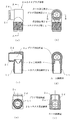
このようにして組み立てられた本発明にかかるL型回転同軸コネクタプラグ1を、パネル等に設けられた特殊な機能を有するダミー内蔵同軸コネクタ200に取り付けた状態を断面図で表した平面図が図4に示されている。
図4に示すように、本発明にかかるL型回転同軸コネクタプラグ1をダミー内蔵同軸コネクタ200に螺着した際に、ダミー内蔵同軸コネクタ200における本体部210の先端が回転取付体21の内周面から立設されているリング状立設部21cの前面に衝合されると共に、前部に設けられている可動絶縁体211もリング状立設部21cの前面に衝合されるようになる。これにより、ダミー内蔵同軸プラグ200のそれ以上の進入は停止されると共に、可動絶縁体211が図示するように後方に移動するようになる。さらに、スイッチ基板213が弾性体214に抗して後方に移動してスイッチ基板213上に搭載されたダミーによる終端が解除されるようになる。このような取付状態において、ダミー内蔵同軸コネクタ200の先端とプラグ用筒状絶縁体23との間には図4に示すようにリング状立設部21cが介在していると共に、リング状立設部21cとプラグ用筒状絶縁体23との間には間隙が存在するようになる。この構成が、本発明の実施の形態のL型回転同軸コネクタプラグ1において、特徴的な構成とされている。
【0027】
これにより、回転取付体21がダミー内蔵同軸コネクタ200に螺着されて固着された際に、上記した間隙の存在によりコネクタプラグ本体2は回転取付体21に対して回転可能となり、コネクタプラグ本体2は被取付体であるダミー内蔵同軸コネクタ200に対して回転可能となる。すなわち、コネクタ部10に同軸ケーブルの先端に設けられた同軸プラグが接続されていて、この同軸ケーブルに捻れ等が発生して応力が発生された際に、同軸ケーブルがコネクタプラグ本体2と共に回転して応力を取り除くことができるようになる。
【0028】
また、本発明にかかるL型回転同軸コネクタプラグ1を、パネル等に設けられた特殊な先端形状の同軸コネクタ160に取り付けた状態を断面図で表した上面図が図5に示されている。
図5に示すように、本発明にかかるL型回転同軸コネクタプラグ1を同軸コネクタ160に螺着した際に、同軸コネクタ160のテーパが形成されて径がすぼめられている先端テーパ部160aが、回転取付体21の内周面から立設されているリング状立設部21cの前面に衝合されるようになる。これにより、同軸コネクタ160の径がすぼめられた先端テーパ部160aのそれ以上の進入は停止される。この状態において、同軸コネクタ160の先端とプラグ用筒状絶縁体23との間には図5に示すようにリング状立設部21cが介在していると共に、リング状立設部21cとプラグ用筒状絶縁体23との間には間隙が存在するようになる。
【0029】
これにより、回転取付体21が同軸コネクタ160に螺着されて固着された際に、上記した間隙の存在によりコネクタプラグ本体2は回転取付体21に対して回転可能となり、コネクタプラグ本体2は被取付体である同軸コネクタ160に対して回転可能となる。すなわち、コネクタ部10に同軸ケーブルの先端に設けられた同軸プラグが接続されていて、この同軸ケーブルに捻れ等が発生して応力が発生された際に、同軸ケーブルがコネクタプラグ本体2と共に回転して応力を取り除くことができるようになる。
なお、リング状立設部21cの高さは、可動絶縁体211の外径や先端テーパ部160aの径より高いと共に、中心導体22に接触しないような高さとすればよいが、カール加工用の工具をリング状立設部21cを通してカール加工を施す都合上から、それらの兼ね合いで決定するようにする。
【0030】
以上説明したように、L型回転同軸コネクタプラグ1のプラグ部20を同軸コネクタ160やダミー内蔵同軸コネクタ200に取り付けた状態において、プラグ部20に対してコネクタ部10が回転可能とされていても、コネクタプラグ本体2と回転取付体21との電気的接続は、その間に介在するリング状スプリング24により行われるようになる。これにより、同軸コネクタ160やダミー内蔵同軸コネクタ200の本体部、回転取付体21およびコネクタプラグ本体2を介して行われるアースの接続が確実に行われるようになる。また、リング状スプリング24は、所定高さを有する係止突起21eにより形成される溝内に収納されているため、平らになるまで押し潰されることはなく、スプリング作用を失うことがないようにされている。
【0031】
また、L型回転同軸コネクタプラグ1を同軸コネクタ160やダミー内蔵同軸コネクタ200に取り付ける際には、回転取付体21を回転させて、回転取付体21の取付ネジ部21dを同軸コネクタ160やダミー内蔵同軸コネクタ200の外周面に形成された雄ネジに螺着することにより行われる。この場合、回転取付体21の長さが長く形成されているので、同軸コネクタ160やダミー内蔵同軸コネクタ200が壁等に埋め込まれるように設けられていても、指で回転取付体21を確実に把持して容易に螺着することができるようになる。
ところで、何らかの原因により回転取付体21が同軸コネクタ160やダミー内蔵同軸コネクタ200に対して緩んだとしても、同軸コネクタ160やダミー内蔵同軸コネクタ200とコネクタプラグ本体2とは、同軸コネクタ160(ダミー内蔵同軸コネクタ200)−回転取付体21−リング状スプリング24−コネクタプラグ本体2の経路により確実に接続されるようになる。このため、L型回転同軸コネクタプラグ1が緩んでしまった場合でも、その挿入損失特性および反射損失特性は広帯域にわたり良好とすることができる。
【0032】
以上説明した本発明にかかるL型回転同軸コネクタプラグは、通信機器やCATV機器等のラックに収納されている回路同士を接続する際のL型プラグとして用いて好適なものとなる。さらに、本発明にかかるL型回転同軸コネクタプラグは、住宅内の壁面に設けられたテレビコンセントに接続するL型プラグとしても用いることができる。
なお、本発明にかかるL型回転同軸コネクタプラグにおける回転取付体21は、上記の説明では外形が六角形とされているとしたが、本発明はこれに限るものではなく外形が六角形以外の多角形としたり、外周面に平目や綾目のローレット加工を施した円形としてもよい。
【0033】
【発明の効果】
本発明は以上説明したように、プラグ部における回転取付体を外部の同軸コネクタに取り付けた際に、同軸コネクタの先端が回転取付体の内周面に形成されているリング状立設部に衝合するようになる。これにより、同軸コネクタの先端の径が細くされている図14に示すような同軸コネクタであっても、取付状態においてコネクタ部をプラグ部に対して回転可能とすることができる。また、同軸コネクタが図15に示すような構造を有していても、可動絶縁体はリング状立設部により確実に押し込められるようになるので、その作用を確実に奏することができるようになる。
【0034】
この結果、L型回転同軸コネクタプラグにおけるコネクタ部に接続されている同軸ケーブルに応力が発生してもその応力は、本体と共に同軸ケーブルが回転することにより取り除かれ、同軸ケーブルに悪影響が残らないようになる。さらに、応力が取り除かれるためL型回転同軸コネクタプラグが緩むことを防止することができるようになる。また、このようにL型回転同軸コネクタプラグを取り付けた状態において本体が回転可能に構成されていても、回転取付体内に収納されたリング状スプリングにより確実なアース接続を行うことができるため、L型回転同軸コネクタプラグの電気的特性が劣化することはない。
【図面の簡単な説明】
【図1】本発明の実施の形態にかかるL型回転同軸コネクタプラグ全体の構成を示す平面図、正面図および底面図である。
【図2】本発明の実施の形態にかかるL型回転同軸コネクタプラグの分解組み立て図である。
【図3】本発明の実施の形態にかかるL型回転同軸コネクタプラグの構成を断面図で表した平面図である。
【図4】本発明の実施の形態にかかるL型回転同軸コネクタプラグを同軸コネクタに取り付けた際の構成を断面図で表した平面図である。
【図5】本発明の実施の形態にかかるL型回転同軸コネクタプラグを同軸コネクタに取り付けた際の構成を断面図で表した上面図である。
【図6】本発明の実施の形態にかかるL型回転同軸コネクタプラグにおける中心コンタクトを収納したコネクタ用筒状絶縁体の構成を示す図である。
【図7】本発明の実施の形態にかかるL型回転同軸コネクタプラグにおけるコネクタプラグ本体の構成を示す図である。
【図8】本発明の実施の形態にかかるL型回転同軸コネクタプラグにおける回転取付体の構成を示す図である。
【図9】本発明の実施の形態にかかるL型回転同軸コネクタプラグにおけるプラグ用筒状絶縁体の構成を示す図である。
【図10】本発明の実施の形態にかかるL型回転同軸コネクタプラグにおける中心導体の構成を示す図である。
【図11】本発明の実施の形態にかかるL型回転同軸コネクタプラグにおける中心コンタクトの構成を示す図である。
【図12】従来提案されているL型同軸コネクタプラグを同軸コネクタに取り付けた際の構成を断面図で表した平面図である。
【図13】一般的な同軸コネクタの構成を断面図で表した平面図である。
【図14】特殊な先端形状の同軸コネクタの構成を断面図で表した平面図である。
【図15】特殊な機能を備える同軸コネクタの構成を断面図で表した平面図である。
【符号の説明】
1 L型回転同軸コネクタプラグ、2 コネクタプラグ本体、2a プラグ用収納室、2b コネクタ用収納室、2c カール加工部、2d 嵌合筒状部、2e三角突部、10 コネクタ部、11 コネクタネジ部、12 コネクタ用筒状絶縁体、12a 筒状部本体、12b 環状突部、12c 貫通孔、12d 第2突部、12e 第1突部、13 中心コンタクト、13a コンタクト基部、13b 挟持部、13c 延伸部、13d 抱持部、20 プラグ部、21 回転取付体、21a スプリング収納部、21b リング状回転係合部、21c リング状立設部、21d 取付ネジ部、21e 係止突起、21f 突出部、22 中心導体、22a 中心導体部、22b テーパ部、22c 嵌合部、22d 接続部、23 プラグ用筒状絶縁体、23a 嵌挿孔、23b 筒状前部、23c 後部、23d 抱持部収納部、23e 後面壁部、24 リング状スプリング、50 同軸コネクタ、100 L型回転同軸コネクタプラグ、102 コネクタプラグ本体、102a プラグ用収納室、102b コネクタ用収納室、110 コネクタ部、112 コネクタ用筒状絶縁体、113 中心コンタクト、113d 抱持部、120 プラグ部、121 回転取付体、121e 停止用リング状突起、122 中心導体、123 プラグ用筒状絶縁体、124 リング状スプリング、150 同軸コネクタ、150a 先端部、160 同軸コネクタ、160a 先端テーパ部、200 ダミー内蔵同軸コネクタ、200ダミー内蔵同軸プラグ、210 本体部、211 可動絶縁体、213 スイッチ基板、214 弾性体[0001]
BACKGROUND OF THE INVENTION
The present invention relates to an L-shaped rotary coaxial connector plug having an L-shape in which a connector portion is provided on one side of the main body and a plug portion is provided on the other side.
[0002]
[Prior art]
Conventionally, in communication equipment, CATV equipment, and the like, each circuit is stored in a rack, and a panel of each circuit is provided on the front surface of the rack. In such a device, when connecting each circuit, a coaxial plug provided on one end of the coaxial cable is connected to a coaxial connector provided on the panel, and provided on the other side of the coaxial cable. The coaxial plug is connected to a coaxial connector provided on a circuit panel to be connected. In this case, when the two coaxial connectors to be connected are arranged close to each other, the coaxial cable is bent and connected in a U shape. When the coaxial cable is bent in a U shape in this way, high frequency characteristics are obtained. It sometimes deteriorated.
[0003]
Therefore, an L-shaped coaxial connector plug is used as an alternative to this, and the coaxial cable is arranged so as to be substantially parallel to the panel. The L-type coaxial connector plug is provided with a connector portion at one end and a plug portion at the other end, and has an L shape as a whole. For this reason, in the L-type coaxial connector plug, the center conductor in the plug portion and the center contact in the connector portion need to be arranged orthogonally inside the main body, and the center conductor and the center contact are arranged in the L-type coaxial connector plug. The connecting work has become complicated, and the configuration of the L-shaped coaxial connector plug itself has become complicated.
[0004]
Therefore, the present applicant has proposed an L-shaped coaxial connector plug as Japanese Patent Application No. 2000-117545, which can simplify the work of connecting the central conductor and the central contact.
In this L-shaped coaxial connector plug, it is possible to achieve an effect that could not be achieved in the past, such that the operation of connecting the center conductor and the center contact can be simplified. However, when the plug portion is screwed to the external coaxial connector, the end of the coaxial connector comes into pressure contact with the plug portion. As a result, the L-type coaxial connector plug cannot be rotated with respect to the attached coaxial connector due to the frictional force between the pressure-welded plug and the tip of the coaxial connector. Therefore, when stress is generated by twisting or the like in the coaxial cable connected to the connector portion in the L-shaped coaxial connector plug, the stress remains applied to the coaxial cable, and the coaxial cable is adversely affected. This could cause damage or loosening of the coaxial connector plug or coaxial connector.
In addition, if the plug portion of the L-type coaxial connector plug becomes loose, the ground connection with the coaxial connector will be incomplete, the insertion loss characteristic and reflection loss characteristic of the L-type coaxial connector plug will deteriorate, and signal transmission and reception will be hindered. It was supposed to give.
[0005]
[Problems to be solved by the invention]
Accordingly, the present applicant has proposed an L-shaped rotary coaxial connector plug in which the connector portion can rotate with respect to the plug portion in the attached state as Japanese Patent Application No. 2000-255042.
This L-shaped rotary coaxial connector plug can exhibit an epoch-making effect that the connector portion can rotate with respect to the plug portion in the attached state. However, if the tip of the coaxial connector to which the L-shaped rotary coaxial connector plug is attached has a special shape, the connector portion may not be able to rotate with respect to the plug portion in the attached state. It was. Furthermore, when the coaxial connector has a structure for having a special action, there is a possibility that the special action may not be performed when the L-type rotary coaxial connector plug is attached.
[0006]
This problem will be described below with reference to FIGS.
FIG. 12 is a sectional view showing a state in which the L-shaped rotary coaxial connector plug 100 is attached to the coaxial connector 150. As shown in this figure, a connector part 110 is provided on one side of a connector plug body 102 formed in an L shape, and a plug part 120 is provided on the other side. The connector part 110 includes an insulative connector tubular insulator 112 fitted in a connector storage chamber 102b having a substantially cylindrical cross section in the connector plug main body 102. This connector tubular insulator 112 holds a center contact 113, so that the center contact 113 is disposed substantially on the center axis of the connector storage chamber 102b. The plug portion 120 has a substantially cylindrical cross section, and has an insulating plug cylindrical insulation in the
[0007]
The rear end of the center conductor 122 is inserted into a holding portion 113d formed at the rear end of the center contact 113, and the center conductor 122 and the center contact 113 are electrically connected. A rotary attachment body 121 is attached to one end of the connector plug body 102 with a ring-
[0008]
When the L-shaped rotary coaxial connector plug 100 having such a configuration is screwed to the coaxial connector 150 as shown in FIG. 13, the distal end portion 150 a of the coaxial connector 150 is fitted to the stop ring-
However, when such an L-shaped rotary coaxial connector plug 100 is attached to a coaxial connector 160 having a special shape in which the tip
[0009]
In order to prevent this, it is considered that the front surface of the plug tubular insulator 123 may be moved backward from the illustrated case. However, when the front surface of the plug tubular insulator 123 is moved backward, the L-type rotary coaxial connector plug 100 is attached to the dummy built-in coaxial connector 200 as shown in FIG. 15A according to Japanese Patent No. 2978144. However, it will be terminated with a dummy. The reason for this will be described by briefly explaining the operation of the dummy built-in coaxial connector 200. When the L-shaped rotary coaxial connector plug 100 is attached to the dummy built-in coaxial connector 200, the tip of the main body 210 of the dummy built-in coaxial connector 200 abuts on the stop ring-
[0010]
At this time, if the movable insulator 211 comes into contact with the tip end surface of the plug tubular insulator 123, it is pushed into the main body 210 against the elasticity of the elastic body 214, and the switch as shown in FIG. The substrate 213 moves rearward. Then, the electrical connection between the switch board 213 and the main body 210 is cut off, and the termination by the dummy incorporated in the switch board 213 is released. However, when the front surface of the plug tubular insulator 123 is moved backward, the tip of the main body 210 of the dummy built-in coaxial connector 200 collides with the stop ring-shaped
[0011]
Therefore, the present invention is capable of rotating the connector portion with respect to the plug portion in a mounted state even with a special tip-shaped coaxial connector, and exerts its action when attached to a coaxial connector having a special function. An object of the present invention is to provide an L-shaped rotary coaxial connector plug that can be used.
[0012]
[Means for Solving the Problems]
In order to achieve the above object, an L-shaped coaxial connector plug is provided with a connector portion on one side of an L-shaped main body and a plug portion on the other side, An insulating cylindrical insulator for a connector fitted in a connector storage chamber having a substantially cylindrical cross section, and a substantially center of the connector storage chamber by being held by the connector cylindrical insulator The plug portion has a substantially cylindrical cross section and is fitted in the plug storage chamber of the main body disposed substantially orthogonal to the connector storage chamber. A cylindrical insulator for plugs that is attached, and being held by the cylindrical insulator for plugs, is arranged on a substantially central axis of the plug storage chamber, and a rear end of the central contact is At the rear edge Inserted into the formed holding part A central conductor electrically connected to the body; On the other A rotary mounting body that is rotatably fixed to the end portion and that can be fixed to an external coaxial connector, and substantially vertical at a predetermined height so as not to contact the central conductor. On the inner peripheral surface of the rotating mounting body A ring-like standing portion that is erected, and when the rotary mounting body is attached to an external coaxial connector, the tip of the coaxial connector is the ring-like standing portion. Front of The main body can be rotated with respect to the rotary mounting body.
[0013]
In the L-shaped rotary coaxial connector plug of the present invention, the tip edge is formed on the inner peripheral surface of the rotating attachment body by processing the tip edge of the main body to have a larger diameter. The rotation attachment body is rotatably engaged with the engagement portion, and the rotation attachment body is rotatably fixed to the main body, and the fitting cylindrical portion on the inner peripheral surface of the rotation attachment body and the front end portion of the main body A ring-shaped spring may be interposed between the outer peripheral surface of the ring.
Furthermore, in the L-shaped rotary coaxial connector plug of the present invention, the ring-shaped spring may be stored so as not to come out from a groove of a spring storage portion formed on the inner peripheral surface of the rotary attachment body.
[0014]
According to the present invention, when the rotary attachment body in the plug portion is attached to the external coaxial connector, the tip of the coaxial connector is in contact with the ring-like standing portion formed on the inner peripheral surface of the rotary attachment body. Come together. Thereby, even if it is a coaxial connector as shown in FIG. 14 with which the diameter of the front-end | tip of a coaxial connector is made thin, a connector part can be made rotatable with respect to a plug part in an attachment state. Further, even if the coaxial connector has a structure as shown in FIG. 15, the movable insulator can be surely pushed in by the ring-like standing portion, so that the operation can be surely performed. .
[0015]
As a result, even if stress is generated in the coaxial cable connected to the connector portion of the L-shaped rotary coaxial connector plug, the stress is removed by the rotation of the coaxial cable together with the main body, so that no adverse effect is left on the coaxial cable. become. Furthermore, since the stress is removed, the L-shaped rotary coaxial connector plug can be prevented from loosening. Further, even if the main body is configured to be rotatable with the L-shaped rotary coaxial connector plug attached in this way, a reliable ground connection can be made by the ring-shaped spring housed in the rotary attachment body. The electrical characteristics of the mold rotary coaxial connector plug do not deteriorate.
[0016]
DETAILED DESCRIPTION OF THE INVENTION
FIG. 1 shows the overall configuration of an L-shaped rotary coaxial connector plug according to an embodiment of the present invention. 1A is a plan view of an L-shaped rotary coaxial connector plug according to the present invention, FIG. 1B is a front view thereof, and FIG. 1C is a bottom view thereof.
As shown in FIGS. 1 (a), (b), and (c), an L-shaped rotary
[0017]
The detailed configuration of the L-type rotary
[0018]
First, an assembling method of the L-shaped rotary
The
[0019]
Next, as shown in FIG. 2, the center contact 13 is held substantially along the central axis in the connector storage chamber 2b of the connector screw portion 11 formed substantially orthogonal to the other end of the
[0020]
Thus, when the connector cylindrical insulator 12 is fitted into the connector storage chamber 2b, the first protrusion 12e and the second protrusion 12d formed at the rear end of the connector cylindrical insulator 12 are formed. As a result, the ring-shaped protrusion formed at the back of the connector storage chamber 2b is sandwiched as shown in FIGS. Further, the rear end portion of the connector tubular insulator 12 where the first protrusion 12 e is formed is fitted into the rear portion 23 c of the
[0021]
Here, the center contact 13 will be described with reference to FIG. When the coaxial plug provided at the tip of the coaxial cable is attached to the connector portion 10, the central conductor of the coaxial plug is inserted into the center contact 13 so that the two are electrically connected. The center contact 13 is made by processing a metal plate. As shown in FIG. 11E, the cross section is a hexagonal contact base portion 13a, for example, and a sandwich extending forward from the contact base portion 13a. It is comprised from the part 13b and the extending | stretching part 13c extended | stretched back from the contact base 13a. In addition, a holding portion 13 d that elastically holds the central conductor 22 in the plug portion 20 is formed at the tip of the extending portion 13 c in a direction substantially orthogonal to the central axis of the central contact 13. As shown in FIG. 11 (g), the sandwiching portion 13b is bent in a U-shaped cross section so as to have a sufficient sandwiching force, and its tip is widened to be the central conductor of the coaxial plug. Has been easy to insert. Further, the sandwiching portion 13b can be sandwiched even if it is a central conductor having a different diameter to some extent because of its structure, and electrical connection can be reliably performed. Further, a slit is formed in the holding portion 13d in the vertical direction over the entire length, so that the holding portion 13d can hold the center conductor 22 with elasticity.
[0022]
When the center contact 13 is held by the connector cylindrical insulator 12 and stored in the connector storage chamber 2b, the holding portion 13d is plugged in the
[0023]
Then, until the tip of the connecting portion 22d is inserted as shown in FIG. 3 into the holding hole formed in the rear wall portion 23e of the
[0024]
Next, the rotary attachment body 21 is attached to the fitting
[0025]
The ring-shaped
Thereby, the plug part 20 comes to be comprised as shown in FIG.
[0026]
A plan view showing the state in which the L-shaped rotary
As shown in FIG. 4, when the L-shaped rotary
[0027]
As a result, when the rotary attachment body 21 is screwed and fixed to the dummy built-in coaxial connector 200, the
[0028]
FIG. 5 is a top view showing the state in which the L-shaped rotary
As shown in FIG. 5, when the L-shaped rotary
[0029]
As a result, when the rotary attachment body 21 is screwed and fixed to the coaxial connector 160, the
The height of the ring-shaped standing portion 21c may be higher than the outer diameter of the movable insulator 211 and the diameter of the tip tapered
[0030]
As described above, even when the plug portion 20 of the L-shaped rotary
[0031]
Further, when the L-shaped rotary
By the way, even if the rotary mounting body 21 is loosened with respect to the coaxial connector 160 or the dummy built-in coaxial connector 200 for some reason, the coaxial connector 160 or dummy built-in coaxial connector 200 and the
[0032]
The L-type rotary coaxial connector plug according to the present invention described above is suitable for use as an L-type plug when connecting circuits stored in a rack such as a communication device or a CATV device. Furthermore, the L-type rotary coaxial connector plug according to the present invention can also be used as an L-type plug connected to a television outlet provided on a wall surface in a house.
In the above description, the outer shape of the rotary attachment body 21 in the L-shaped rotary coaxial connector plug according to the present invention is hexagonal. However, the present invention is not limited to this and the outer shape is not hexagonal. It may be a polygonal shape or a circular shape with a knurled finish on the outer peripheral surface.
[0033]
【The invention's effect】
As described above, according to the present invention, when the rotary attachment body in the plug portion is attached to the external coaxial connector, the tip of the coaxial connector is opposed to the ring-like standing portion formed on the inner peripheral surface of the rotary attachment body. Come together. Thereby, even if it is a coaxial connector as shown in FIG. 14 with which the diameter of the front-end | tip of a coaxial connector is made thin, a connector part can be rotated with respect to a plug part in an attachment state. Further, even if the coaxial connector has a structure as shown in FIG. 15, the movable insulator can be reliably pushed in by the ring-like standing portion, so that the operation can be surely performed. .
[0034]
As a result, even if stress is generated in the coaxial cable connected to the connector portion of the L-shaped rotary coaxial connector plug, the stress is removed by the rotation of the coaxial cable together with the main body, so that no adverse effect is left on the coaxial cable. become. Furthermore, since the stress is removed, the L-shaped rotary coaxial connector plug can be prevented from loosening. Further, even if the main body is configured to be rotatable with the L-shaped rotary coaxial connector plug attached in this way, a reliable ground connection can be made by the ring-shaped spring housed in the rotary attachment body. The electrical characteristics of the mold rotary coaxial connector plug do not deteriorate.
[Brief description of the drawings]
FIG. 1 is a plan view, a front view, and a bottom view showing the overall configuration of an L-shaped rotary coaxial connector plug according to an embodiment of the present invention.
FIG. 2 is an exploded view of an L-shaped rotary coaxial connector plug according to an embodiment of the present invention.
FIG. 3 is a plan view showing the configuration of an L-shaped rotary coaxial connector plug according to an embodiment of the present invention in a cross-sectional view.
FIG. 4 is a plan view showing the configuration when the L-shaped rotary coaxial connector plug according to the embodiment of the present invention is attached to the coaxial connector in a cross-sectional view.
FIG. 5 is a top view showing the configuration when the L-shaped rotary coaxial connector plug according to the embodiment of the present invention is attached to the coaxial connector in a cross-sectional view.
FIG. 6 is a view showing a configuration of a tubular insulator for a connector that houses a center contact in an L-shaped rotary coaxial connector plug according to an embodiment of the present invention.
FIG. 7 is a diagram showing a configuration of a connector plug body in the L-type rotary coaxial connector plug according to the embodiment of the present invention.
FIG. 8 is a diagram showing a configuration of a rotary attachment body in the L-shaped rotary coaxial connector plug according to the embodiment of the present invention.
FIG. 9 is a diagram showing a configuration of a plug cylindrical insulator in the L-type rotary coaxial connector plug according to the embodiment of the present invention.
FIG. 10 is a diagram showing a configuration of a central conductor in an L-shaped rotary coaxial connector plug according to an embodiment of the present invention.
FIG. 11 is a diagram showing a configuration of a center contact in the L-type rotary coaxial connector plug according to the embodiment of the present invention.
FIG. 12 is a plan view showing a cross-sectional view of a configuration when a conventionally proposed L-shaped coaxial connector plug is attached to a coaxial connector.
FIG. 13 is a plan view showing a configuration of a general coaxial connector in a cross-sectional view.
FIG. 14 is a plan view showing the configuration of a special tip-shaped coaxial connector in a cross-sectional view.
FIG. 15 is a plan view showing a configuration of a coaxial connector having a special function in a cross-sectional view.
[Explanation of symbols]
1 L-type rotary coaxial connector plug, 2 connector plug body, 2a plug storage chamber, 2b connector storage chamber, 2c curled portion, 2d fitting cylindrical portion, 2e triangular protrusion, 10 connector portion, 11 connector screw portion , 12 Tubular insulator for connector, 12a tubular body, 12b annular projection, 12c through hole, 12d second projection, 12e first projection, 13 center contact, 13a contact base, 13b clamping portion, 13c Part, 13d holding part, 20 plug part, 21 rotation attachment body, 21a spring storage part, 21b ring-shaped rotation engagement part, 21c ring-shaped standing part, 21d attachment screw part, 21e locking projection, 21f protrusion part, 22 center conductor, 22a center conductor part, 22b taper part, 22c fitting part, 22d connection part, 23 tubular insulator for plug, 23a fitting insertion hole, 23b tubular form Part, 23c rear part, 23d holding part storage part, 23e rear surface wall part, 24 ring-shaped spring, 50 coaxial connector, 100 L-type rotary coaxial connector plug, 102 connector plug body, 102a plug storage room, 102b connector storage room , 110 connector part, 112 cylindrical insulator for connector, 113 center contact, 113d holding part, 120 plug part, 121 rotating mounting body, 121e stop ring projection, 122 center conductor, 123 cylindrical insulator for plug, 124 ring spring, 150 coaxial connector, 150a tip, 160 coaxial connector, 160a tip taper, 200 dummy built-in coaxial connector, 200 dummy built-in coaxial plug, 210 body, 211 movable insulator, 213 switch board, 214 elastic body
Claims (3)
前記コネクタ部は、前記本体における断面が略円筒状とされたコネクタ用収納室内に嵌着された絶縁性のコネクタ用筒状絶縁体と、該コネクタ用筒状絶縁体で保持されることにより、前記コネクタ用収納室の略中心軸上に配置された中心コンタクトとからなり、
前記プラグ部は、断面が略円筒状とされていると共に、前記コネクタ用収納室と略直交して配置された前記本体におけるプラグ用収納室内に嵌着された絶縁性のプラグ用筒状絶縁体と、該プラグ用筒状絶縁体で保持されることにより、前記プラグ用収納室の略中心軸上に配置されて、後端が前記中心コンタクトの後端に形成された抱持部に嵌入されて電気的に接続されている中心導体と、前記本体の他方における端部に回転可能に固着されていると共に、外部の同軸コネクタに固着可能とされている回転取付体と、前記中心導体に接触しないように所定の高さでほぼ垂直に前記回転取付体の内周面に立設されているリング状立設部とからなり、
前記回転取付体を外部の同軸コネクタに取り付けた際に、該同軸コネクタの先端が前記リング状立設部の前面に衝合することにより、前記本体が前記回転取付体に対して回転可能とされていることを特徴とするL型回転同軸コネクタプラグ。An L-shaped coaxial connector plug in which a connector part is provided on one side of a main body formed in an L shape and a plug part is provided on the other side,
The connector portion is held by an insulating connector tubular insulator fitted in a connector storage chamber having a substantially cylindrical cross section in the main body, and the connector tubular insulator. It consists of a center contact disposed on a substantially central axis of the connector storage chamber,
The plug portion has a substantially cylindrical cross section, and is an insulating tubular insulator for a plug that is fitted in the plug storage chamber of the main body that is disposed substantially orthogonal to the connector storage chamber. And by being held by the plug tubular insulator, the rear end of the plug storage chamber is fitted into a holding portion formed at the rear end of the center contact. a central conductor being electrically connected Te, along with and is rotatably fixed to an end portion of the other of the body, and rotating the mounting member and is capable of sticking to the outside of the coaxial connector, in contact with the center conductor A ring-like standing portion that is erected on the inner peripheral surface of the rotary mounting body substantially vertically at a predetermined height so as not to
When the rotary attachment body is attached to an external coaxial connector, the end of the coaxial connector abuts against the front surface of the ring-like standing portion , so that the main body can be rotated with respect to the rotary attachment body. An L-shaped rotary coaxial connector plug characterized in that
Priority Applications (1)
| Application Number | Priority Date | Filing Date | Title |
|---|---|---|---|
| JP2001233832A JP3682003B2 (en) | 2001-08-01 | 2001-08-01 | L-type rotary coaxial connector plug |
Applications Claiming Priority (1)
| Application Number | Priority Date | Filing Date | Title |
|---|---|---|---|
| JP2001233832A JP3682003B2 (en) | 2001-08-01 | 2001-08-01 | L-type rotary coaxial connector plug |
Publications (2)
| Publication Number | Publication Date |
|---|---|
| JP2003045587A JP2003045587A (en) | 2003-02-14 |
| JP3682003B2 true JP3682003B2 (en) | 2005-08-10 |
Family
ID=19065555
Family Applications (1)
| Application Number | Title | Priority Date | Filing Date |
|---|---|---|---|
| JP2001233832A Expired - Fee Related JP3682003B2 (en) | 2001-08-01 | 2001-08-01 | L-type rotary coaxial connector plug |
Country Status (1)
| Country | Link |
|---|---|
| JP (1) | JP3682003B2 (en) |
-
2001
- 2001-08-01 JP JP2001233832A patent/JP3682003B2/en not_active Expired - Fee Related
Also Published As
| Publication number | Publication date |
|---|---|
| JP2003045587A (en) | 2003-02-14 |
Similar Documents
| Publication | Publication Date | Title |
|---|---|---|
| TWI787278B (en) | Connecting device for connecting and grounding coaxial cable connectors | |
| US6116945A (en) | Microphone connector assembly | |
| TWI558022B (en) | Push-on cable connector with a coupler and retention and release mechanism | |
| US4339166A (en) | Connector | |
| JP3102892B2 (en) | Cable connection element | |
| JP3217785B2 (en) | Electrical connector | |
| US8439707B2 (en) | Compression connector for multi-conductor cable | |
| US9252507B2 (en) | Terminal block | |
| US20110306226A1 (en) | Protruding contact receiver for multi-conductor compression cable connector | |
| US8162697B1 (en) | Tip-sleeve silent plug with 360° sliding ring contact | |
| US20160380374A1 (en) | Plug-in connector | |
| JP4430214B2 (en) | L-type rotary coaxial connector plug | |
| JP2009093830A (en) | Universally rotatable coaxial terminal | |
| JP2001135372A (en) | Lever terminal | |
| JP3682002B2 (en) | L-type rotary coaxial connector plug | |
| JP3682003B2 (en) | L-type rotary coaxial connector plug | |
| JP3306009B2 (en) | Coaxial plug for electronic equipment | |
| US5628644A (en) | Negligible insert force power connector | |
| US7367842B2 (en) | Coaxial connecting plug | |
| US5071366A (en) | Circular IDC connector | |
| JP2707302B2 (en) | Tapped electrical connector assembly | |
| US20030073337A1 (en) | Cable end connector | |
| JP3094428U (en) | RF cable connection structure | |
| JP4074141B2 (en) | Dummy built-in coaxial connector | |
| EP0124300A2 (en) | Connector for coaxial cable |
Legal Events
| Date | Code | Title | Description |
|---|---|---|---|
| A977 | Report on retrieval |
Free format text: JAPANESE INTERMEDIATE CODE: A971007 Effective date: 20040615 |
|
| A131 | Notification of reasons for refusal |
Free format text: JAPANESE INTERMEDIATE CODE: A131 Effective date: 20040629 |
|
| A521 | Written amendment |
Free format text: JAPANESE INTERMEDIATE CODE: A523 Effective date: 20040819 |
|
| TRDD | Decision of grant or rejection written | ||
| A01 | Written decision to grant a patent or to grant a registration (utility model) |
Free format text: JAPANESE INTERMEDIATE CODE: A01 Effective date: 20050517 |
|
| A61 | First payment of annual fees (during grant procedure) |
Free format text: JAPANESE INTERMEDIATE CODE: A61 Effective date: 20050519 |
|
| R150 | Certificate of patent or registration of utility model |
Free format text: JAPANESE INTERMEDIATE CODE: R150 |
|
| FPAY | Renewal fee payment (event date is renewal date of database) |
Free format text: PAYMENT UNTIL: 20090527 Year of fee payment: 4 |
|
| FPAY | Renewal fee payment (event date is renewal date of database) |
Free format text: PAYMENT UNTIL: 20090527 Year of fee payment: 4 |
|
| FPAY | Renewal fee payment (event date is renewal date of database) |
Free format text: PAYMENT UNTIL: 20100527 Year of fee payment: 5 |
|
| FPAY | Renewal fee payment (event date is renewal date of database) |
Free format text: PAYMENT UNTIL: 20110527 Year of fee payment: 6 |
|
| FPAY | Renewal fee payment (event date is renewal date of database) |
Free format text: PAYMENT UNTIL: 20120527 Year of fee payment: 7 |
|
| FPAY | Renewal fee payment (event date is renewal date of database) |
Free format text: PAYMENT UNTIL: 20120527 Year of fee payment: 7 |
|
| FPAY | Renewal fee payment (event date is renewal date of database) |
Free format text: PAYMENT UNTIL: 20130527 Year of fee payment: 8 |
|
| FPAY | Renewal fee payment (event date is renewal date of database) |
Free format text: PAYMENT UNTIL: 20130527 Year of fee payment: 8 |
|
| R250 | Receipt of annual fees |
Free format text: JAPANESE INTERMEDIATE CODE: R250 |
|
| LAPS | Cancellation because of no payment of annual fees |