JP3680896B2 - Optical scanning device - Google Patents
Optical scanning device Download PDFInfo
- Publication number
- JP3680896B2 JP3680896B2 JP24097597A JP24097597A JP3680896B2 JP 3680896 B2 JP3680896 B2 JP 3680896B2 JP 24097597 A JP24097597 A JP 24097597A JP 24097597 A JP24097597 A JP 24097597A JP 3680896 B2 JP3680896 B2 JP 3680896B2
- Authority
- JP
- Japan
- Prior art keywords
- scanning
- scanning direction
- optical system
- sub
- light beam
- Prior art date
- Legal status (The legal status is an assumption and is not a legal conclusion. Google has not performed a legal analysis and makes no representation as to the accuracy of the status listed.)
- Expired - Fee Related
Links
Images


Description
【0001】
【発明の属する技術分野】
本発明は、レーザービームプリンタ等に用いられる光走査装置に係り、特に、特に回転多面鏡等の複数の反射面を有する偏向器に光ビームを順に2度入射させる光走査装置において、第1反射面から第2反射面に伝達入射させる伝達光学系の構成に関するものである。
【0002】
【従来の技術】
レーザービームプリンタ等の画像記録装置や、各種画像読込み、測定装置に用いられる光走査装置においては、光ビームを偏向走査する偏向器として回転多面鏡が多く用いられてきた。
【0003】
これらの装置においては、被走査面上において直線あるいは曲線上に光ビームを繰り返し走査し、被走査面に位置する被走査媒体を前記の走査方向とはおおむね直交方向に相対移動させ2次元の走査を行う。前者の光走査装置による走査方向を主走査方向、後者の被走査媒体の相対移動方向を副走査方向とする。
【0004】
近年、上記の装置においては、解像度や処理速度の向上のため、より高速の光走査装置が求められるようになってきている。光ビームの偏向に回転多面鏡を用いた光走査装置では、走査速度(走査周波数)を上げるためには、
(1)回転多面鏡の回転数を上げる。
(2)回転多面鏡の面数を増加させる。
の2つの方法が考えられる。
【0005】
回転多面鏡の回転数を上げるためには、高速回転可能な軸受が必要になるが、現在最も多く用いられているボールベアリングでは、毎分20000回転程度が上限となる。エアベアリングを用いれば、毎分30000回転以上の回転数で使用可能であるが、軸受が高価なため使用できる装置が限られる。特に、一般消費者向けの安価なレーザービームプリンタ等には使えない。
【0006】
一方、回転多面鏡の面数を増加させると、1つの反射面当りの回転角度が小さくなってしまう。また、個々の反射面の大きさを一定以上確保しようとすると、回転多面鏡の直径が大きくなってしまう。
【0007】
光走査装置では、被走査面上に光ビームを結像させて用いることが多いが、レーザービームを走査する場合、小さなスポットに結像させるには、光ビームの拡がり角に応じて回転多面鏡の反射面は主走査方向にある一定の大きさが必要である。ところが、回転多面鏡の面数を増加させた場合、1つの反射面での回転角度が小さいため光ビームの走査角も小さくなる。光ビームの走査角が小さいと、所定の走査幅を得るためには走査光学系の焦点距離が長くなり、回転多面鏡から被走査面までの光路長も伸びる。このため、回転多面鏡の反射面上での光ビームの主走査方向の直径も大きくなり、面数が少ない場合に比べてより反射面が大きくなり、さらに一層回転多面鏡の大きさが増加する。
【0008】
すなわち、回転多面鏡の面数が増加するに従って必要な反射面の大きさは面数の少ない場合に比べてより大きくなるという矛盾した特性を持つため、回転多面鏡の大きさ(内接円筒の大きさ)が決まれば、面数の上限が決まる。例えば、レーザービームプリンタに用いる光走査装置において、所要走査幅350mm、波長780nm、回転多面鏡の内接円筒の半径を25mm、被走査面での主走査方向のスポット直径を50μm以下にする場合、面数はおおむね7面が上限となる。
【0009】
そこで、面数を多く取るために、回転多面鏡の直径を大きくすると、回転多面鏡の重量や慣性2次モーメントが増加し、回転に伴う空気抵抗(風損)も増加するので、回転数が低く制限される。
【0010】
このように、回転多面鏡の面数、回転数共上限があるので、それを越える走査速度を得るために様々な光走査装置が考案されてきた。
【0011】
例えば、特開昭51−100742号に記載された技術では、光源に半導体レーザーアレーを用い、同時に複数のレーザービームで被走査面を走査することで走査速度を向上させている。この方法によれば、回転多面鏡の回転数を上げることなく、素子に集積されたレーザーの個数だけ走査速度を早めることができる。
【0012】
一方、特開昭51−32340号のものでは、光源から射出された光ビームを主走査方向に非常に直径の小さい状態で回転多面鏡に入射させ、偏向された光ビームを伝達光学系を介して再び回転多面鏡に入射させる方法が開示されている。すなわち、回転多面鏡に光ビームを2度入射させている。
【0013】
後者の方法においては、光ビームが最初に回転多面鏡に入射するときの主走査方向の光ビームの直径を2回目に入射する場合に比べて極めて小さくし、かつ、2回目に回転多面鏡に入射する光ビームが回転する反射面の主走査方向の中心点を追従するように伝達光学系を構成している。
【0014】
このように構成することで、光ビームが最初に回転多面鏡に入射する際には、光ビームの直径を極端に小さくできるので、回転多面鏡の分割角度一杯まで走査可能となる。第1の反射面で偏向された光ビームが伝達光学系を経由して2回目に回転多面鏡に入射する際には、光ビームの直径は被走査面上で所定のスポットを得るのに必要な大きさに拡大されるものの、反射面の回転に追従するため、回転多面鏡の回転角度とは無関係に光ビームの大きさを設定できる。
なお、特開昭51−32340号には、伝達光学系を主走査方向においてアフォーカル光学系にすることが記載されている。
【0015】
一方、光走査装置において、回転多面鏡の回転軸に垂直な走査面に対し角度を持って光ビームを入射させ偏向を行うものが、例えば特開平1−169422号等において知られている。
【0016】
上記のように回転多面鏡の異なる反射面に順に2度入射させることを、本明細書においては「2度入射」と呼ぶことにする。また、回転多面鏡の走査面に角度を有して光ビームを入射させることを、「斜め入射」と呼ぶことにする。
【0017】
【発明が解決しようとする課題】
上記のような従来の2度入射の光走査装置において、伝達光学系をアフォーカル光学系にすると、アフォーカル光学系を構成する前群と後群が必要になる。また、伝達光学系の副走査方向に面倒れ補正機能を持たせると、副走査方向にパワーを有するレンズも必要になる。
【0018】
このようなことから、伝達光学系を構成する伝達レンズは枚数が多く複雑な系になってしまう。また、伝達光学系の折り曲げ光路を形成する第1伝達ミラーと第2伝達ミラーの間にレンズを配置するためには、伝達光学系の前群、回転多面鏡、第1伝達ミラー、第2伝達ミラーと伝達光学系中の光ビームとの干渉を避けなければならず、配置が困難であったり、配置位置に制約があり、最も光学特性が良い構成をとるこが困難であった。
【0019】
本発明は従来技術のこのような点に鑑みてなされたものであり、その目的は、2度入射の光走査装置において、伝達光学系のアフォーカル光学系の後群の機能と面倒れ補正のためのレンズの機能とを折り曲げ光路を形成するミラーに持たせてレンズの枚数を削減して簡素な伝達光学系とすることである。
【0020】
【課題を解決するための手段】
上記目的を達成する本発明の光走査装置は、光ビームを発生する光源と、前記光源からの光ビームを反射偏向させる複数の反射面を有する偏向器と、前記偏向器の第1反射面により反射偏向された光ビームを前記偏向器の第2反射面の回転に追従するように前記第2反射面に伝達入射させる伝達光学系と、前記偏向器の前記第2反射面により反射偏向された光ビームを被走査面上にビームスポットを形成させて走査させる走査光学系とを備えた光走査装置において、
前記伝達光学系中に2面の反射鏡を有し、その中の少なくとも1面の反射鏡が、主走査方向の曲率半径と副走査方向の曲率半径とが異なるトーリック面又は副走査方向において凹のシリンドリカル面からなることを特徴とするものである。
【0021】
この場合、伝達光学系は、主走査方向において正屈折力を有する前群と正屈折力を有する後群からなるアフォーカル光学系を構成しており、副走査方向において正屈折力を有していて第1反射面と第2反射面とを共役にしており、その後群がその2面の反射鏡を有し、その中、主走査方向において少なくとも一方の反射鏡が凹面で、それらの合成屈折力は正であり、副走査方向において少なくとも一方の反射鏡が凹面で、それらの合成屈折力は正であることが望ましい。
【0022】
また、偏向器は回転軸を挟んで互いに平行で互いに180°の角度をなして対向する対をなした複数組の反射面を有する回転多面鏡からなり、光源からの光ビームは第1反射面に副走査方向に角度を持って入射し、伝達光学系により伝達された光ビームは第2反射面に副走査方向に角度を持って入射する配置になっており、第1反射面と第2反射面は前記回転多面鏡の回転軸を挟んで互いに平行で互いに180°の角度をなして対向する反射面に設定されているようにすることができる。
【0023】
その場合には、光源からの光ビームを第1反射面へ入射させる光学系の光軸、伝達光学系の光軸、走査光学系の光軸が、回転多面鏡の回転軸を含む共通の副走査面内に配置されているようにすることが望ましい。
【0024】
本発明においては、伝達光学系中に2面の反射鏡を有し、その中の少なくとも1面の反射鏡が、主走査方向の曲率半径と副走査方向の曲率半径とが異なるトーリック面又は副走査方向において凹のシリンドリカル面からなるので、伝達光学系のアフォーカル光学系の後群の機能、面倒れ補正のためのレンズの機能等をこの2面の反射鏡に持たせることができ、レンズの構成枚数を削減して簡素な伝達光学系とすることができ、高速で良好な画像再現が可能な光走査装置を軽量で部品点数を少なく構成することができる。
【0025】
【発明の実施の形態】
以下、図面に基づき本発明の光走査装置について詳細に説明する。
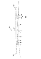
まず、本発明の光走査装置の実施例について説明する。図1は本実施例の光走査装置の構成を示す平面図、図2はその側面図、図3はその主要部の斜視図、図4はその主要部の側面図である。以下、本発明では、光学系の任意の位置において、その位置における光学系の光軸を含み偏向器である回転多面鏡4の回転軸41に平行な面を副走査面と定義し、光軸を含み副走査面に垂直な面を主走査面と定義する。さらに、主走査面内において、光軸に垂直な方向を主走査方向と定義し、また、副走査面内において、光軸に垂直な方向を副走査方向と定義する。
【0026】
光源としての半導体レーザー1から射出した光ビームは、アパーチャ61(図5)、第1整形レンズ2、第2整形レンズ3を透過して整形され、偏向器としての回転多面鏡4の第1反射面5に入射し、1度目の偏向がなされる。このとき、光ビームは、回転多面鏡4の回転軸41に垂直な面に対して角度を持って第1反射面5に入射するため、入射する光ビームと反射された光ビームは干渉しない。第1反射面5で反射された光ビームは、第1伝達レンズ7、第2伝達レンズ8、第3伝達レンズ9を透過して第1伝達ミラー10で反射され、次いで第2伝達ミラー13で反射され、再び回転多面鏡4の第2反射面6に入射し、2度目の偏向がなされる。このときも、光ビームは、回転多面鏡4の回転軸41に垂直な面に対して角度を持って第2反射面6に入射するため、入射する光ビームと反射された光ビームは干渉しない。
【0027】
第2反射面6で反射された光ビームは、第1走査レンズ14、第2走査レンズ15及び第3走査レンズ16により被走査面17上に光ビームスポットとして結像されて走査される。回転多面鏡4の面数は12面(偶数)である。第3走査レンズ16は、副走査方向に偏心しており、その方向は図2中の矢印の方向である。第3走査レンズ16をこのように偏心させる理由は、回転多面鏡4の第2反射面6で反射され偏向される光ビームは円錐状の軌跡を描き、その光ビームの断面の座標系が偏向角に依存して回転してしまい、被走査面17上の結像スポットの形状が崩れてしまうが、第3走査レンズ16をこのように偏心させることにより、その崩れが防止できるからである。
【0028】
ところで、半導体レーザー1から第1反射面5までの間の光学系を整形光学系21、第1反射面5から第2反射面6の間の光学系を伝達光学系22、第2反射面6から被走査面17までの間の光学系を走査光学系23と称するとすると、回転多面鏡4の第1反射面5と第2反射面6は回転軸41を挟んで対向する相互に平行な反射面であり、かつ、整形光学系21、伝達光学系22、走査光学系23の光軸は回転軸41を含む共通の副走査面内に配置されている。したがって、この光走査装置は、2度入射で斜め入射でありながら、この副走査面に関して対称な構成になっている。このような配置にすると、整形光学系21、伝達光学系22、走査光学系23の光軸が主走査面で見て一直線上に配置されるので、構造上の主走査方向の基準面が1面に集約され、光学系を構成する各要素を高精度に配置することができる。また、主走査面で見て、伝達光学系22の光軸が整形光学系21及び走査光学系23の光軸と一部重なるため、少ないスペースで配置でき、光走査装置の設置面積の減少、装置の小型化が図れる。そして、このような配置により、回転多面鏡4の回転軸41の偏心に基づく走査線の副走査方向での位置変動を防止することができる。
【0029】
図5に、整形光学系21の主走査方向の光路図(a)と副走査方向の光路図(b)を示す。主走査面に垂直で副走査面に平行な接合面を備えカバーガラスを有する半導体レーザー1から副走査方向に比べて主走査方向により広がるように射出された光ビームbは、第1整形レンズ2の入射面位置に配置された矩形開口のアパーチャ61によって周辺部が遮蔽され、非球面コリメータレンズを構成する第1整形レンズ2により平行な光ビームに変換される。第2整形レンズ2は副走査方向にのみ正屈折力を有する正シリンドリカルレンズである。そのため、第2整形レンズ2を透過した光ビームは、主走査面において平行な光ビームとして第1反射面5に入射し、副走査面においては第1反射面5近傍に結像(収束)する。
【0030】
図6に、伝達光学系22の主走査方向の光路図(a)と副走査方向の光路図(b)を示す。第1伝達レンズ7、第2伝達レンズ8、第3伝達レンズ9は何れも主走査方向にのみ屈折力を有するシリンドリカルレンズであり、第1伝達レンズ7と第2伝達レンズ8は正シリンドリカルレンズ、第3伝達レンズ9は負シリンドリカルレンズであり、これら3枚で主走査方向正屈折力伝達レンズ群24を構成している。また、第1伝達ミラー10は凹の球面鏡であり、第2伝達ミラー13は主走査断面、副走査断面共凹のトーリック反射面であり、副走査断面を副走査方向に平行な軸の周りに回転させて形成される面である。そして、これらの作用は、第1伝達ミラー10と第2伝達ミラー13は主走査方向において合成で正屈折力(屈折系でないので、パワーと呼ぶ方がより正しい。)の合成系を形成しており、第1反射面5で反射された光ビームは、主走査面において、主走査方向正屈折力伝達レンズ群24により一旦結像する。伝達レンズ群24の像側焦点と、第1伝達ミラー10と第2伝達ミラー13からなる合成系の物体側焦点とは一致していて、主走査面においてアフォーカル光学系を構成している。したがって、主走査面において、主走査方向正屈折力伝達レンズ群24がアフォーカル光学系の前群を構成し、第1伝達ミラー10と第2伝達ミラー13からなる合成系がアフォーカル光学系の後群を構成している。そのため、光ビームは、第2伝達ミラー13で主走査面内で再び平行な光ビームに変換され、第2反射面6に入射する。副走査面においては、第1伝達ミラー10と第2伝達ミラー13の合成正屈折力により、第1反射面5と第2反射面6とは共役関係になっており、第1反射面5近傍の収束点を第2反射面6近傍に再び結像する。
【0031】
図7に、走査光学系23の主走査方向の光路図(a)と副走査方向の光路図(b)を示す。第1走査レンズ14は正屈折力を有する球面レンズである。第2走査レンズ15は副走査方向にのみ屈折作用を有するプリズムであり、第3走査レンズ16は樹脂製の主走査方向に長い長尺レンズである。第3走査レンズ16の入射面は、主走査方向に曲率半径の大きな凹形状となっており、副走査面方向には曲率半径の小さな凸形状となっており、主走査方向の断面曲線をその入射面よりも被走査面17側に位置する主走査方向に平行な軸の回りに回転させることにより形成される面である。このような面は鞍型トーリック面とも呼ばれる。また、第3走査レンズ16の射出面は、主走査方向で曲率半径の大きな凸形状の非円弧状であり、副走査方向の断面形状は直線であり屈折力を有さない。このような構成の走査光学系23は、副走査面において、第2反射面6と被走査面17を共役関係にして、第2反射面6近傍の収束点を被走査面17近傍に結像する。また、主走査面においては、第2反射面6から反射された平行な光ビームを被走査面17近傍に結像する。
【0032】
次に、伝達光学系22の作用について説明する。図8は伝達光学系22の主走査面の断面展開図である。第1伝達レンズ7、第2伝達レンズ8、第3伝達レンズ9により構成される主走査方向正屈折力伝達レンズ群24を、簡素化して単レンズとして示してある。また、第1伝達ミラー10と第2伝達ミラー13からなる合成系も、簡素化して正屈折力の単レンズ12として示してある。図8(a)と(b)に回転多面鏡4が回転するときの光ビームの状態を示す。ところで、図1〜図4等に示すように、伝達光学系22の光路は、伝達ミラー10、13により2回反射される。すなわち、偶数回反射される。図8では、これらの偶数回の反射について展開しているので、図8(b)のように、第1反射面5と第2反射面6の回転方向は同じである。
【0033】
第1反射面5に入射する平行な光ビームの直径はwi である。伝達光学系22は主走査面内ではアフォーカル光学系を構成しているので、第2反射面6に入射する光ビームも平行であり、光ビームの直径はwo である。伝達レンズ群24の焦点距離をf1 、第1伝達ミラー10と第2伝達ミラー13からなる合成系12の焦点距離をf2 とすると、wo をwi で除した光ビームの直径の比の値は、f2 をf1 で除した値に等しい。
【0034】
図8(b)に示すように、回転多面鏡4が角度θ1 だけ回転すると、第1反射面5で光ビームは角度2θ1 だけ偏向される。偏向された光ビームは伝達レンズ群24、合成系12を透過して、角度θ2 だけ偏向される。この光ビームは点Qで光軸と交差する。第2反射面6上において、偏向された光ビームと光軸との距離はdであるが、回転多面鏡4が角度θ1 だけ回転すると、第2反射面6も同じ距離dだけ移動するような位置関係に設定される。したがって、光ビームの移動量と第2反射面6の移動量が一致し、第2反射面6から光ビームがはみ出すことはない。
【0035】
このとき、偏向された光ビームは、第2反射面6に対して角度θ2 だけ入射角が増大する側に偏向されるので、第2反射面6で反射された光ビームの走査角θs は、θs =2θ1 +θ2 と表わされる。
【0036】
本実施例の伝達光学系22は主走査面においてアフォーカル光学系であるので、その光学倍率βは焦点距離f2 を焦点距離f1 で除した値であり、上記のように、光ビームの直径の比wo /wi にも等しい。また、伝達光学系22を透過する光ビームは角度2θ1 から角度θ2 に偏向角が変化するので、光学倍率βは2θ1 /θ2 と表すこともできる。したがって、光学倍率βは次式で表される。
【0037】
β=wo /wi =f2 /f1 =2θ1 /θ2
本実施例では光学倍率βを、1<β<20としている。
【0038】
本実施例のような回転多面鏡4で光ビームが2度の偏向をされる光走査装置は、従来の1度しか偏向されない光走査装置に比べて、走査速度を速くすることができる。このことについて次に説明する。
【0039】
従来の1度しか偏向しない光走査装置では、回転多面鏡が回転すると反射面が移動するため、1回の走査において常に光ビーム全体を同一反射面に入れるために、回転多面鏡に入射する光ビームの主走査方向の大きさよりも、反射面の大きさを大きくしなければならない。したがって、回転多面鏡の反射面の面数をあまり多くすることができない。
【0040】
本実施例では、主走査面において、第1反射面5に平行な光ビームが入射する。また、β>1であるため、第1反射面5上における光ビームの主走査方向の直径wi は、第2反射面6上における光ビームの主走査方向の直径wo よりも小さい。そのため、従来の光走査装置に対して第1反射面5の大きさが小さくても、1回の走査において常に光ビーム全体を同一反射面に入れることができる。wi を小さくすればする程、さらに第1反射面5の大きさを小さくすることができる。また、2度目の偏向では、回転多面鏡4が回転したときの光ビームの移動量と第2反射面6の移動量が一致するため、第2反射面6の主走査方向の大きさは、少なくとも入射する光ビームの大きさと同じ大きさだけあればよい。
【0041】
したがって、従来の1度しか偏向しない光走査装置に比べて、本実施例の2度の偏向をする光走査装置では、第2反射面6上における光ビームの主走査方向の直径wo に対して、第1反射面5上における光ビームの主走査方向の直径wi を小さくすることにより、回転多面鏡4の反射面を小さくすることができるため、反射面の面数を多くすることができ、それだけ走査速度を上げることができる。
【0042】
このように構成された光走査装置の具体的な第1実施例の数値例を表−1に示す。この表−1では、シリンドリカル面、トーリック面は副走査方向、主走査方向の曲率半径をrix、riyとしている(iは光源1から被走査面17までの面番号を示す。)。また、非球面である面については、曲率半径は光軸上の値を示している。なお、長さの単位はmmである。
【0043】

第2整形レンズ2及び第3走査レンズ16の非球面を表す式は、
zi =(y2 /ri )/[1+{1−(Ki +1)(y/ri )2 }1/2 ]+Ai y4 +Bi y6 +Ci y8
であり、その非球面係数を次の表−2に示す。
【0045】
この具体例において、第3走査レンズ16の入射面S21は、r21y =−1475.39378の円弧をr21x =37.95675で回転させて形成されるトーリック面である。なお、第2走査レンズ15、第3走査レンズ16を通過するときのように、光路が屈折されるときは、光軸は主光線と同じように屈折されるものとし、表−1、表−2のパラメータの基準となる光軸は、常に走査中心を走査するビームの主光線に一致するものとする。
【0047】
また、回転多面鏡4の面数は12、その内接円直径は38.64mmであり、回転多面鏡4の第1反射面5、第2反射面6への光ビームの副走査方向の入射角は何れも6°であり、第1伝達ミラー10、第2伝達ミラー13への光ビームの副走査方向の入射角は何れも3°である。また、第2走査レンズ15の射出面S20は副走査断面において13°傾いており、第3走査レンズ16の入射面S21は副走査断面において8.750387°傾いており、第3走査レンズ16の射出面S22は副走査断面において2.875374°傾いている。これらの傾き角の向きについては、図2、図4参照。
【0048】
また、第1整形レンズ入射面S3 に一致して、主走査方向0.7154mm、副走査方向1.0526mmの矩形のアパーチャ61が配置されている。そして、副走査方向において、発光点1と回転多面鏡4の第1反射面5は幾何光学的共役関係から外れている。ただし、回転多面鏡4の第1反射面5、第2反射面6、被走査面17の3面は、何れも互いに共役関係にあるため、回転多面鏡4の面倒れ補正が行われている。したがって、発光点1と被走査面17は共役関係から外れている。しかしながら、回折の影響により、光ビームが最小となる位置(ビームウエスト)は幾何光学的結像点からずれた位置にあり、光ビームが略最小となる位置(ビームウエスト)に被走査面17が配置されている。
【0049】
なお、上記具体例の伝達光学系22の主走査方向の光学倍率βは8.05、副走査方向の光学倍率βt は0.579、走査光学系23の副走査方向の光学倍率βs は0.406である。
【0050】
ここで、第2走査レンズ15は、前記したように、副走査方向にのみ屈折作用を有するプリズムである。このプリズムの作用について説明する。回転多面鏡4の反射面6で反射され偏向された光ビームは円錐状の軌跡を描き、第2走査レンズ15のプリズムを配置しない場合、第3走査レンズ16の長尺レンズ上で湾曲したビーム軌跡となってしまう。このプリズム16は、図9に模式的に示すように、円錐状の光ビームaの軌跡を第3走査レンズ16の入射面上で直線状のビーム軌跡Aに変換する作用を有している。
【0051】
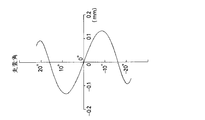
図10は、上記の具体例の第3走査レンズ16の入射面におけるビーム軌跡を示した図であり、そのビーム軌跡を実線で示す。なお、図のY方向が主走査方向、X方向が副走査方向を示す。比較のために、上記具体例の光学系の回転多面鏡4の第2反射面6から第3走査レンズ16までの距離は変えずに、第2走査レンズ15のみを取り除いた場合の、第3走査レンズ16の入射面におけるビームの軌跡を破線で示す。図10より、第2走査レンズ15のプリズム作用によりビームの軌跡を直線状に補正する作用があることが分かる。
【0052】
図11は、第3走査レンズ16の副走査断面を主走査方向の数か所(5か所)の位置で示したもので、断面形状の設計値に対する測定値の誤差を示したものである。図中、X、Y、Zはそれぞれ副走査方向、主走査方向、光軸方向とする。図11のように、第3走査レンズ16のような鞍型トーリック面を持つレンズの形状誤差は、主走査方向の位置によらず略同じ様子を示すが、副走査方向に周期的に変化する特徴がある。上記のように、第2走査レンズ15のプリズム作用により、第3走査レンズ16上のビーム軌跡は直線Aとなり、ビームは主走査方向の位置に係わらず点B1 〜B5 の常に形状誤差が凸の部分に入射する。主走査方向の何れの位置においても、第3走査レンズ16の形状誤差が凸の部分に光ビームが入射すると、副走査方向の結像位置は設計された位置より手前にずれるが、走査領域全体にわたって常に同一量だけ手前にずれるため、第3走査レンズ16の位置を調整する等、光学系の調整をすれば補正することが可能であり、このような調整により像面湾曲は生じない。
【0053】
さて、ここで、伝達光学系22に要求される特性について説明すると、主走査方向では面追従特性と平行性の2つ、副走査方向では像面湾曲特性の1つである。
【0054】
主走査方向の面追従特性とは、図8を用いて説明したように、回転多面鏡4が回転したときに第2反射面6の移動量と第2反射面6に入射する光ビームの移動量とが一致することである。また、主走査方向の平行性とは、伝達光学系22から射出される光ビームの平行性が走査している間常に維持されることである。副走査方向の像面湾曲特性とは、第2反射面6での像面湾曲、すなわち、副走査方向における第2反射面6近傍の結像点による像面湾曲のことである。
【0055】
主走査方向の特性を満足させる構成について、面追従特性が悪いと、第2反射面6に入射する光ビームが第2反射面6からはみ出し、ビームスポットの拡大や光パワーの損失を引き起こす。第2反射面6からはみ出さなくても、第2反射面6の面精度が良好な領域からはみ出せば、ビームスポットの形状の崩れを引き起こす。第2反射面6の移動量と第2反射面6に入射する光ビームの移動量との差は、実際には0.1mm程度以内であることが望ましい。
【0056】
平行性については、ディオプターの変動幅とディオプターの絶対値の2つの観点がある。ここで、ディオプターとは、第2反射面6から第2反射面6に入射する光ビームの主走査方向の結像点までの距離をm単位で表したものの逆数である。ディオプターの変動幅については、例えば走査角により収束する光ビームが発散する光ビームへ変化するように、走査角による平行性の変動が大きいと、その変動を走査光学系23で補正しきれなくなり、被走査面17の主走査方向の像面湾曲が悪化するため、変動幅は0.02ディオプター以下であることが望ましい。
【0057】
ディオプターの変動幅がレンジで0.02ディオプターである場合について考える。走査中心で0ディオプターであり、走査領域の端で+0.02ディオプターである場合、焦点距離300mmの走査光学系23で、走査光学系23の主面から300mm離れた被走査面17にビームスポットを結像させると、走査中心では被走査面17上に焦点を結び像面湾曲は0となる。しかしながら、走査領域の端では、走査光学系23に入射する光ビームは、回転多面鏡4の第2反射面6から50000mmの位置に結像する収束する光ビームであるため、走査光学系23により結像する位置は、結像公式より上記主面から298.21mmの位置となり、像面湾曲は約1.8mm生じることとなる。被走査面17上のビームスポットのサイズの変動を10%以下に抑えるためには、通常は像面湾曲はレンジで2mm以下にする必要がある。したがって、ディオプターの変動幅がレンジで0.02ディオプター以下にすれば、ビームスポットのサイズの変動が小さな光走査装置が得られる。
【0058】
ディオプターの絶対値については、走査角による平行性の変化が小さくても、平行からのずれが大きく、収束する光ビームあるいは発散する光ビームとなっていると、回転多面鏡4の各反射面の面毎の位置誤差により、被走査面17上のビームスポットの主走査方向の位置ずれ(ジッタ)を生じるため、絶対値は±1ディオプター以内であることが望ましい。
【0059】
ここで、回転多面鏡4の回転軸41から各反射面までの距離のばらつきを50μm、走査光学系23の焦点距離を300mm、回転多面鏡4に入射する光ビームの入射角の最大値を15°とすると、ディオプターの絶対値が1の発散する光ビームが走査光学系23に入射するとき、ジッタは11.5μmとなる。ジッタはドットピッチのおよそ4分の1であることが望ましく、例えば600dpiの場合、ドットピッチは42μmであるため、ジッタはおよそ11μm以下であることが望ましい。したがって、ディオプターの絶対値が1ディオプター以下であると、ジッタはほとんど目立たなくすることができる。
【0060】
以上から、ディオプターの絶対値は1ディオプターまで許容されるものの、ディオプターの変動幅は0.02ディオプター以下に抑えなければならない。
【0061】
ところで、以上のような特性を持つ伝達光学系22のレンズ構成について検討する。伝達光学系22は主走査面においてアフォーカル光学系であり、途中で一旦結像する。何れも主走査面において正の屈折力を有する前群24と後群12で構成される。図12に示すように、回転多面鏡4の第1反射面5で偏向された光の主光線の集まりcを1つの主光線束とみなすと、伝達光学系22の前群24の入射側の開口数が大きいため、前群24は少なくとも3枚のレンズで構成しなければ以上のような必要な特性が得られない。一方、後群12は入射側の開口数も射出側の開口数も何れも小さいため、正の屈折力を有する2枚の凹面鏡の組み合わせで必要な特性が得られる(図12中では、後群12は単レンズとして示してある。)。
【0062】
上記のように、主走査方向で面追従特性と平行性の2つの特性を満足するために、伝達光学系22の前群24は少なくとも3枚のレンズで構成する必要がある。前記の実施例では、前群24は第1反射面5側から順に、正・正・負の屈折力を有する第1伝達レンズ7、第2伝達レンズ8、第3伝達レンズ9で構成されており、正屈折力と負屈折力を組み合わせることでペッツバール和を小さく抑えている。前群24全体としては正の屈折力を有するので、正屈折力のレンズを2枚、負屈折力のレンズを1枚とすることにより、1枚のレンズの屈折力が極端に大きくならず、良好な面追従特性と平行性を得ている。正屈折力のレンズ2枚、負屈折力のレンズ1枚の組み合わせとしては、図13に示すように、第1反射面5側から順に、正・正・負(図(a))、正・負・正(図(b))、負・正・正(図(c))の3通り存在するが、主面Hに対する位置は、正・正・負の場合は主面Hの後方、正・負・正の場合は主面Hと略同じ位置、負・正・正の場合は主面Hの前方である。その前群24は回転多面鏡4の第1反射面5に入射する光ビームとの干渉を避ける必要があり、前群24の構成としては、主面Hの最も後方に配置できる図13(a)の正・正・負の屈折力配置が望ましい。
【0063】
また、その場合、最も第1反射面5側の正レンズは、射出側の面が凸であることが望ましい。回転多面鏡4の第1反射面5で偏向された光の主光線の集まりcを1つの主光線束とみなすと、伝達光学系22の前群24は発散する主光線束を平行に近い状態に変換する機能を有するが、最も第1反射面5側の正レンズには発散する主光線束が入射するため、入射側に凸のメニスカス形状であると、球面収差の発生が大きくなり、面追従特性が悪くなる。そこで、最も第1反射面5側の正レンズは、入射側に凹のメニスカス形状、平凸形状、あるいは両凸形状、すなわち、射出側の面が凸であることが望ましい。
【0064】
同様に、真中の正レンズは、平行に近い状態の主光線束が入射し、収束する主光線束を射出する。そのため、入射側に凹のメニスカス形状であると、球面収差の発生が大きくなり、面追従特性が悪くなる。そこで、真中の正レンズは、入射側に凸のメニスカス形状、凸平形状、あるいは両凸形状、すなわち、入射側の面が凸であることが望ましい。
【0065】
なお、第3レンズの負レンズは、入射側の面が凹であることが望ましい。前記の表−1及び表−2に示した第1実施例の光走査装置の伝達光学系22の前群24は、主走査断面内で、第1伝達レンズ7は平凸レンズ形状(副走査断面内では両面共平面)、第2伝達レンズ8は凸平レンズ形状(副走査断面内では両面共平面)、第3伝達レンズ9は凹平レンズ形状(副走査断面内では両面共平面)をしている。
【0066】
また、第1伝達ミラー10及び第2伝達ミラー13に関しては、実施例からも明らかなように、主走査方向において少なくとも一方は凹面であり、それらの合成屈折力は正であることを要し、副走査方向において少なくとも一方は凹面であり、それらの合成屈折力は正であって面倒れ補正作用を有する(第1反射面5と第2反射面6とを共役関係にする)ことを要する。
【0067】
なお、図14にこの第1実施例の平行性を示すグラフ(縦軸は走査角、横軸はディオプター)を、図15にこの第1実施例の面追従特性を示すグラフ(縦軸は走査角、横軸は面追従特性)を、さらに、図16に伝達光学系の副走査方向の像面湾曲を示すグラフ(縦軸は像高、横軸は像面湾曲)をそれぞれ示す。
【0068】
次の表−3に、第2実施例の具体的な数値例を示す。ただし、面番号S7 〜S15のみを示し、それ以外は表−1及び表−2の第1実施例と同じであり省く。
【0069】
伝達光学系22の主走査方向の光学倍率βは8.05、副走査方向の光学倍率βt は3.04である。
【0071】
この第2実施例においては、第1伝達ミラー10は主走査断面、副走査断面共凹のトーリック反射面であり、副走査断面を副走査方向に平行な軸の周りに回転させて形成される面である。第2伝達ミラー13は凹の球面鏡である。これらの作用は第1実施例と同様である。図17にこの実施例の副走査方向の像面湾曲を示すグラフを示す。この実施例の平行性を示すグラフは図14と、面追従特性を示すグラフは図15と同じなので省く。
【0072】
次の表−4に、第3実施例の具体的な数値例を示す。ただし、面番号S7 〜S15のみを示し、それ以外は表−1及び表−2の第1実施例と同じであり省く。
【0073】
伝達光学系22の主走査方向の光学倍率βは8.05、副走査方向の光学倍率βt は1.01である。
【0075】
この第3実施例においては、第1伝達ミラー10は主走査断面、副走査断面共凹のトーリック反射面であり、副走査断面を副走査方向に平行な軸の周りに回転させて形成される面である。第2伝達ミラー13も主走査断面、副走査断面共凹のトーリック反射面であり、副走査断面を副走査方向に平行な軸の周りに回転させて形成される面である。これらの作用は第1実施例と同様である。図18にこの実施例の副走査方向の像面湾曲を示すグラフを示す。この実施例の平行性を示すグラフは図14と、面追従特性を示すグラフは図15と同じなので省く。
【0076】
次の表−5に、第4実施例の具体的な数値例を示す。ただし、面番号S7 〜S15のみを示し、それ以外は表−1及び表−2の第1実施例と同じであり省く。
【0077】
伝達光学系22の主走査方向の光学倍率βは8.16、副走査方向の光学倍率βt は2.93である。
【0079】
この第4実施例においては、第1伝達ミラー10は副走査断面が凹のシリンドリカル反射面であり、第2伝達ミラー13は凹の球面鏡である。これらの作用は第1実施例と同様である。図19にこの実施例の平行性を示すグラフを、図20に面追従特性を示すグラフを、さらに、図21に副走査方向の像面湾曲を示すグラフをそれぞれ示す。
【0080】
次の表−6に、第5実施例の具体的な数値例を示す。ただし、面番号S7 〜S15のみを示し、それ以外は表−1及び表−2の第1実施例と同じであり省く。
【0081】
伝達光学系22の主走査方向の光学倍率βは8.16、副走査方向の光学倍率βt は0.288である。
【0083】
この第5実施例においては、第1伝達ミラー10は平面鏡であり、第2伝達ミラー13は主走査断面、副走査断面共凹のトーリック反射面であり、副走査断面を副走査方向に平行な軸の周りに回転させて形成される面である。図22にこの実施例の副走査方向の像面湾曲を示すグラフを示す。この実施例の平行性を示すグラフは図19と、面追従特性を示すグラフは図20と同じなので省く。
【0084】
次の表−7に、第6実施例の具体的な数値例を示す。ただし、面番号S7 〜S15のみを示し、それ以外は表−1及び表−2の第1実施例と同じであり省く。
【0085】
伝達光学系22の主走査方向の光学倍率βは8.16、副走査方向の光学倍率βt は1.00である。
【0087】
この第6実施例においては、第1伝達ミラー10は副走査断面が凹のシリンドリカル反射面である。第2伝達ミラー13は主走査断面、副走査断面共凹のトーリック反射面であり、副走査断面を副走査方向に平行な軸の周りに回転させて形成される面である。図23にこの実施例の副走査方向の像面湾曲を示すグラフを示す。この実施例の平行性を示すグラフは図19と、面追従特性を示すグラフは図20と同じなので省く。
【0088】
なお、以上の実施例では、偏向器として回転多面鏡を使用するものについて説明したが、偏向器として回転多面鏡の他に、回転2面鏡の場合にも同様の効果を達成することができる。
以上、本発明の光走査装置を実施例に基づいて説明してきたが、本発明はこれらに限定されず、種々の変形が可能である。
【0089】
【発明の効果】
以上の説明から明らかなように、本発明の光走査装置によれば、伝達光学系中に2面の反射鏡を有し、その中の少なくとも1面の反射鏡が、主走査方向の曲率半径と副走査方向の曲率半径とが異なるトーリック面又は副走査方向において凹のシリンドリカル面からなるので、伝達光学系のアフォーカル光学系の後群の機能、面倒れ補正のためのレンズの機能等をこの2面の反射鏡に持たせることができ、レンズの構成枚数を削減して簡素な伝達光学系とすることができ、高速で良好な画像再現が可能な光走査装置を軽量で部品点数を少なく構成することができる。
【図面の簡単な説明】
【図1】本発明の光走査装置の1実施例の構成を示す平面図である。
【図2】図1の光走査装置の側面図である。
【図3】図1の光走査装置の主要部の斜視図である。
【図4】図1の光走査装置の主要部の側面図である。
【図5】図1の光走査装置の整形光学系の主走査方向と副走査方向の光路図である。
【図6】図1の光走査装置の伝達光学系の主走査方向と副走査方向の光路図である。
【図7】図1の光走査装置の走査光学系の主走査方向と副走査方向の光路図である。
【図8】伝達光学系の作用を説明するための主走査面の断面展開図である。
【図9】屈折プリズムの補正作用を説明するための図である。
【図10】本発明の1つの具体例の第3走査レンズの入射面におけるビーム軌跡を示した図である。
【図11】本発明の1つの具体例において像面湾曲が発生しない理由を説明するための図である。
【図12】伝達光学系の構成を説明するための主走査面の断面展開図である。
【図13】伝達光学系の前群のレンズ構成を検討するための図である。
【図14】第1実施例の平行性を示すグラフである。
【図15】第1実施例の面追従特性を示すグラフである。
【図16】第1実施例の像面湾曲を示すグラフである。
【図17】第2実施例の像面湾曲を示すグラフである。
【図18】第3実施例の像面湾曲を示すグラフである。
【図19】第4実施例の平行性を示すグラフである。
【図20】第4実施例の面追従特性を示すグラフである。
【図21】第4実施例の像面湾曲を示すグラフである。
【図22】第5実施例の像面湾曲を示すグラフである。
【図23】第6実施例の像面湾曲を示すグラフである。
【符号の説明】
1…半導体レーザー(光源)
2…第1整形レンズ
3…第2整形レンズ
4…回転多面鏡
5…回転多面鏡の第1反射面
6…回転多面鏡の第2反射面
7…第1伝達レンズ
8…第2伝達レンズ
9…第3伝達レンズ
10…第1伝達ミラー
12…第1伝達ミラーと第2伝達ミラーからなる合成系(伝達光学系の後群)
13…第2伝達ミラー
14…第1走査レンズ
15…第2走査レンズ(プリズム)
16…第3走査レンズ(長尺レンズ)
17…被走査面
21…整形光学系
22…伝達光学系
23…走査光学系
24…主走査方向正屈折力伝達レンズ群(伝達光学系の前群)
41…回転多面鏡の回転軸
61…アパーチャ[0001]
BACKGROUND OF THE INVENTION
The present invention relates to an optical scanning device used in a laser beam printer or the like, and more particularly, in an optical scanning device in which a light beam is incident twice in order on a deflector having a plurality of reflecting surfaces such as a rotary polygon mirror. The present invention relates to a configuration of a transmission optical system that transmits light from a surface to a second reflecting surface.
[0002]
[Prior art]
In an image recording apparatus such as a laser beam printer and an optical scanning apparatus used in various image reading and measuring apparatuses, a rotating polygon mirror has been often used as a deflector for deflecting and scanning a light beam.
[0003]
In these apparatuses, two-dimensional scanning is performed by repeatedly scanning a light beam on a scanning surface on a straight line or a curve, and relatively moving a scanning medium positioned on the scanning surface in a direction substantially orthogonal to the scanning direction. I do. The scanning direction by the former optical scanning device is the main scanning direction, and the relative movement direction of the latter scanning medium is the sub-scanning direction.
[0004]
In recent years, higher speed optical scanning devices have been required for the above-described devices in order to improve resolution and processing speed. In an optical scanning device using a rotating polygon mirror for deflecting a light beam, in order to increase the scanning speed (scanning frequency),
(1) Increase the rotational speed of the rotary polygon mirror.
(2) Increase the number of surfaces of the rotating polygon mirror.
There are two possible methods.
[0005]
In order to increase the rotational speed of the rotary polygon mirror, a bearing capable of high-speed rotation is required. However, with the most frequently used ball bearings, the upper limit is about 20,000 revolutions per minute. If an air bearing is used, it can be used at a rotational speed of 30000 revolutions per minute or more, but the apparatus that can be used is limited because the bearing is expensive. In particular, it cannot be used for an inexpensive laser beam printer for general consumers.
[0006]
On the other hand, when the number of surfaces of the rotating polygon mirror is increased, the rotation angle per one reflecting surface is decreased. Also, if the size of each reflecting surface is to be secured above a certain level, the diameter of the rotating polygon mirror will increase.
[0007]
In an optical scanning device, a light beam is often formed on a surface to be scanned, but when a laser beam is scanned, a rotating polygon mirror is used in order to form an image on a small spot depending on the divergence angle of the light beam. The reflecting surface needs to have a certain size in the main scanning direction. However, when the number of surfaces of the rotary polygon mirror is increased, the scanning angle of the light beam is also reduced because the rotation angle on one reflecting surface is small. If the scanning angle of the light beam is small, the focal length of the scanning optical system becomes long to obtain a predetermined scanning width, and the optical path length from the rotary polygon mirror to the surface to be scanned also increases. For this reason, the diameter of the light beam in the main scanning direction on the reflecting surface of the rotating polygon mirror also increases, the reflecting surface becomes larger than when the number of surfaces is small, and the size of the rotating polygon mirror further increases. .
[0008]
In other words, the size of the rotating polygon mirror (the size of the inscribed cylinder) is inconsistent with the increase in the number of surfaces of the rotating polygon mirror because the required size of the reflecting surface becomes larger than when the number of surfaces is small. If the size is determined, the upper limit of the number of faces is determined. For example, in an optical scanning device used for a laser beam printer, when the required scanning width is 350 mm, the wavelength is 780 nm, the radius of the inscribed cylinder of the rotary polygon mirror is 25 mm, and the spot diameter in the main scanning direction on the scanned surface is 50 μm or less, The upper limit of the number of faces is generally seven.
[0009]
Therefore, increasing the diameter of the rotating polygon mirror to increase the number of surfaces increases the weight and inertial moment of inertia of the rotating polygon mirror, and increases the air resistance (windage loss) associated with the rotation. Limited to low.
[0010]
Thus, since there are upper limits on the number of surfaces and the number of rotations of the rotary polygon mirror, various optical scanning devices have been devised in order to obtain a scanning speed exceeding the upper limit.
[0011]
For example, in the technique described in JP-A-51-100742, a semiconductor laser array is used as a light source, and the scanning surface is simultaneously scanned with a plurality of laser beams to improve the scanning speed. According to this method, the scanning speed can be increased by the number of lasers integrated in the element without increasing the rotational speed of the rotary polygon mirror.
[0012]
On the other hand, in Japanese Patent Application Laid-Open No. 51-32340, a light beam emitted from a light source is incident on a rotating polygon mirror in a main scanning direction with a very small diameter, and the deflected light beam is transmitted through a transmission optical system. A method of re-entering the rotating polygon mirror is disclosed. That is, the light beam is incident twice on the rotating polygon mirror.
[0013]
In the latter method, the diameter of the light beam in the main scanning direction when the light beam is first incident on the rotary polygon mirror is made extremely small compared to the case where the light beam is incident on the second time. The transmission optical system is configured so that the incident light beam follows the center point in the main scanning direction of the rotating reflecting surface.
[0014]
With this configuration, when the light beam first enters the rotating polygon mirror, the diameter of the light beam can be made extremely small, so that the scanning can be performed up to the full dividing angle of the rotating polygon mirror. When the light beam deflected by the first reflecting surface enters the rotary polygon mirror for the second time via the transmission optical system, the diameter of the light beam is necessary to obtain a predetermined spot on the surface to be scanned. Although it is enlarged to a large size, the size of the light beam can be set regardless of the rotation angle of the rotary polygon mirror in order to follow the rotation of the reflecting surface.
Japanese Patent Laid-Open No. 51-32340 describes that the transmission optical system is an afocal optical system in the main scanning direction.
[0015]
On the other hand, in an optical scanning device, a device that makes a light beam incident and deflects at an angle with respect to a scanning surface perpendicular to the rotation axis of the rotary polygon mirror is known, for example, in JP-A-1-169422.
[0016]
In this specification, the incidence on the reflecting surfaces of the rotating polygonal mirrors twice in order as described above will be referred to as “double incidence”. Further, the incidence of the light beam with an angle on the scanning surface of the rotary polygon mirror is referred to as “oblique incidence”.
[0017]
[Problems to be solved by the invention]
In the conventional double-incidence optical scanning apparatus as described above, if the transmission optical system is an afocal optical system, a front group and a rear group that constitute the afocal optical system are required. In addition, if a surface tilt correction function is provided in the sub-scanning direction of the transmission optical system, a lens having power in the sub-scanning direction is also required.
[0018]
For this reason, the number of transfer lenses constituting the transfer optical system becomes a complicated system with a large number of lenses. Further, in order to dispose the lens between the first transmission mirror and the second transmission mirror that form the bending optical path of the transmission optical system, the front group of the transmission optical system, the rotating polygon mirror, the first transmission mirror, and the second transmission mirror are used. Interference between the mirror and the light beam in the transmission optical system has to be avoided, and the arrangement is difficult, and the arrangement position is limited, making it difficult to obtain a configuration with the best optical characteristics.
[0019]
The present invention has been made in view of the above-described points of the prior art, and an object of the present invention is to perform functions of the rear group of the afocal optical system of the transmission optical system and surface tilt correction in a two-incident optical scanning device. The function of the lens for this purpose is to be provided in a mirror that forms a bent optical path, thereby reducing the number of lenses and providing a simple transmission optical system.
[0020]
[Means for Solving the Problems]
An optical scanning device of the present invention that achieves the above object includes a light source that generates a light beam, a deflector having a plurality of reflecting surfaces that reflect and deflect the light beam from the light source, and a first reflecting surface of the deflector. A transmission optical system that transmits and reflects the reflected and deflected light beam to the second reflecting surface so as to follow the rotation of the second reflecting surface of the deflector, and is reflected and deflected by the second reflecting surface of the deflector. In an optical scanning device including a scanning optical system that scans a light beam by forming a beam spot on a surface to be scanned,
The transmission optical system has two reflecting mirrors, and at least one of the reflecting mirrors is concave in the toric surface or the sub-scanning direction in which the curvature radius in the main scanning direction and the curvature radius in the sub-scanning direction are different. It is characterized by comprising a cylindrical surface.
[0021]
In this case, the transmission optical system constitutes an afocal optical system including a front group having positive refractive power in the main scanning direction and a rear group having positive refractive power, and has positive refractive power in the sub-scanning direction. The first reflecting surface and the second reflecting surface are conjugated, and the subsequent group has two reflecting mirrors, of which at least one reflecting mirror is concave in the main scanning direction, and their combined refraction. It is desirable that the force is positive, at least one of the reflecting mirrors is concave in the sub-scanning direction, and their combined refractive power is positive.
[0022]
The deflector is composed of a rotating polygon mirror having a plurality of pairs of reflecting surfaces that are parallel to each other with an angle of 180 ° across the rotation axis, and the light beam from the light source is the first reflecting surface. Is incident on the second reflecting surface with an angle in the sub-scanning direction. The first reflecting surface and the second reflecting surface are incident on the second reflecting surface with an angle in the sub-scanning direction. The reflection surfaces may be set to be reflection surfaces that are parallel to each other across the rotation axis of the rotary polygon mirror and that are opposed to each other at an angle of 180 °.
[0023]
In that case, the optical axis of the optical system that causes the light beam from the light source to enter the first reflecting surface, the optical axis of the transmission optical system, and the optical axis of the scanning optical system include a common sub-mirror including the rotation axis of the rotary polygon mirror. It is desirable to arrange them in the scanning plane.
[0024]
In the present invention, the transmission optical system has two reflecting mirrors, and at least one of the reflecting mirrors is a toric surface or sub-surface having different curvature radii in the main scanning direction and curvature radii in the sub scanning direction. Since it consists of a cylindrical surface that is concave in the scanning direction, this two-surface reflecting mirror can have the functions of the rear group of the afocal optical system of the transmission optical system, the function of the lens for surface tilt correction, etc. Thus, a simple optical transmission system can be obtained by reducing the number of components, and an optical scanning device capable of high-speed and good image reproduction can be configured with a light weight and a small number of components.
[0025]
DETAILED DESCRIPTION OF THE INVENTION
The optical scanning device of the present invention will be described below in detail with reference to the drawings.
First, an embodiment of the optical scanning device of the present invention will be described. FIG. 1 is a plan view showing the configuration of the optical scanning device of this embodiment, FIG. 2 is a side view thereof, FIG. 3 is a perspective view of the main part thereof, and FIG. 4 is a side view of the main part thereof. Hereinafter, in the present invention, at an arbitrary position of the optical system, a surface that includes the optical axis of the optical system at that position and is parallel to the
[0026]
The light beam emitted from the
[0027]
The light beam reflected by the second reflecting
[0028]
By the way, the optical system between the
[0029]
FIG. 5 shows an optical path diagram (a) in the main scanning direction and an optical path diagram (b) in the sub-scanning direction of the shaping
[0030]
FIG. 6 shows an optical path diagram (a) in the main scanning direction and an optical path diagram (b) in the sub-scanning direction of the transmission
[0031]
FIG. 7 shows an optical path diagram (a) in the main scanning direction and an optical path diagram (b) in the sub-scanning direction of the scanning
[0032]
Next, the operation of the transmission
[0033]
The diameter of the parallel light beam incident on the first reflecting
[0034]
As shown in FIG. 8B, when the rotary polygon mirror 4 rotates by the angle θ 1 , the light beam is deflected by the angle 2θ 1 on the first reflecting
[0035]
At this time, the deflected light beam is deflected to the side where the incident angle increases by an angle θ 2 with respect to the second reflecting
[0036]
Since the transmission
[0037]
β = w o / w i = f 2 / f 1 = 2θ 1 / θ 2
In this embodiment, the optical magnification β is 1 <β <20.
[0038]
The optical scanning device in which the light beam is deflected twice by the rotary polygon mirror 4 in this embodiment can increase the scanning speed as compared with the conventional optical scanning device in which the light beam is deflected only once. This will be described next.
[0039]
In a conventional optical scanning device that deflects only once, the reflecting surface moves when the rotating polygon mirror rotates, so that the light incident on the rotating polygon mirror always enters the same reflecting surface in one scan. The size of the reflecting surface must be larger than the size of the beam in the main scanning direction. Therefore, the number of reflecting surfaces of the rotary polygon mirror cannot be increased too much.
[0040]
In this embodiment, a light beam parallel to the first reflecting
[0041]
Therefore, in comparison with the conventional optical scanning device that deflects only once, in the optical scanning device that deflects twice according to the present embodiment, the light beam on the second reflecting
[0042]
Table 1 shows a numerical example of a specific first embodiment of the optical scanning apparatus configured as described above. In Table 1, the cylindrical surface and the toric surface have the radius of curvature in the sub-scanning direction and the main scanning direction as r ix and r iy (i indicates the surface number from the
[0043]
The expressions representing the aspheric surfaces of the
z i = (y 2 / r i ) / [1+ {1− (K i +1) (y / r i ) 2 } 1/2 ] + A i y 4 + B i y 6 + C i y 8
The aspheric coefficient is shown in the following Table-2.
[0045]
In this specific example, the incident surface S 21 of the
[0047]
The number of surfaces of the rotating polygon mirror 4 is 12, and the inscribed circle diameter is 38.64 mm, and the light beam is incident on the first reflecting
[0048]
In addition, a
[0049]
In the transmission
[0050]
Here, as described above, the
[0051]
FIG. 10 is a diagram showing a beam locus on the incident surface of the
[0052]
FIG. 11 shows the sub-scanning cross section of the
[0053]
Now, the characteristics required for the transmission
[0054]
As described with reference to FIG. 8, the surface follow-up characteristics in the main scanning direction are the amount of movement of the second reflecting
[0055]
With respect to a configuration that satisfies the characteristics in the main scanning direction, if the surface following characteristics are poor, the light beam incident on the second reflecting
[0056]
There are two aspects of parallelism: diopter fluctuation range and diopter absolute value. Here, the diopter is the reciprocal of the distance from the second reflecting
[0057]
Consider the case where the variation range of the diopter is 0.02 diopter in the range. When the scanning center is 0 diopter and the end of the scanning region is +0.02 diopter, the scanning
[0058]
As for the absolute value of the diopter, even if the change in parallelism due to the scanning angle is small, the deviation from the parallel is large, and if the light beam converges or diverges, A positional error (jitter) in the main scanning direction of the beam spot on the surface to be scanned 17 is caused by the position error for each surface, so that the absolute value is preferably within ± 1 diopter.
[0059]
Here, the dispersion of the distance from the
[0060]
From the above, although the absolute value of diopter is allowed up to 1 diopter, the fluctuation range of diopter must be suppressed to 0.02 diopter or less.
[0061]
By the way, the lens configuration of the transmission
[0062]
As described above, in order to satisfy the two characteristics of the surface following characteristic and the parallelism in the main scanning direction, the
[0063]
In this case, it is desirable that the positive lens closest to the first reflecting
[0064]
Similarly, the central positive lens emits a principal ray bundle that is incident on a principal ray bundle in a state of being nearly parallel and converges. Therefore, when the concave meniscus shape is on the incident side, the occurrence of spherical aberration is increased, and the surface following characteristics are deteriorated. Therefore, it is desirable that the middle positive lens has a convex meniscus shape, a convex flat shape, or a biconvex shape on the incident side, that is, the incident side surface is convex.
[0065]
The negative lens of the third lens preferably has a concave surface on the incident side. The
[0066]
Further, as is clear from the embodiment, the
[0067]
FIG. 14 is a graph showing the parallelism of the first embodiment (vertical axis is scanning angle, horizontal axis is diopter), and FIG. 15 is a graph showing surface following characteristics of the first embodiment (vertical axis is scanning). FIG. 16 is a graph showing the field curvature in the sub-scanning direction of the transmission optical system (the vertical axis is the image height and the horizontal axis is the field curvature).
[0068]
Table 3 below shows specific numerical examples of the second embodiment. However, only the surface number S 7 to S 15, the other is the same as the first embodiment in Table 1 and Table 2 omitted.
[0069]
The optical magnification β in the main scanning direction of the transmission
[0071]
In the second embodiment, the
[0072]
Table 4 below shows specific numerical examples of the third embodiment. However, only the surface number S 7 to S 15, the other is the same as the first embodiment in Table 1 and Table 2 omitted.
[0073]
The optical magnification β in the main scanning direction of the transmission
[0075]
In the third embodiment, the
[0076]
Table 5 below shows specific numerical examples of the fourth embodiment. However, only the surface number S 7 to S 15, the other is the same as the first embodiment in Table 1 and Table 2 omitted.
[0077]
The optical magnification β of the transmission
[0079]
In the fourth embodiment, the
[0080]
The following Table-6 shows specific numerical examples of the fifth embodiment. However, only the surface number S 7 to S 15, the other is the same as the first embodiment in Table 1 and Table 2 omitted.
[0081]
The optical magnification β in the main scanning direction of the transmission
[0083]
In the fifth embodiment, the
[0084]
Table 7 below shows specific numerical examples of the sixth embodiment. However, only the surface number S 7 to S 15, the other is the same as the first embodiment in Table 1 and Table 2 omitted.
[0085]
The optical magnification β of the transmission
[0087]
In the sixth embodiment, the
[0088]
In the above embodiment, the rotating polygon mirror is used as the deflector. However, in addition to the rotating polygon mirror as the deflector, the same effect can be achieved in the case of the rotating dihedral mirror. .
The optical scanning device according to the present invention has been described based on the embodiments. However, the present invention is not limited to these, and various modifications can be made.
[0089]
【The invention's effect】
As is apparent from the above description, according to the optical scanning device of the present invention, the transmission optical system has two reflecting mirrors, and at least one of the reflecting mirrors has a radius of curvature in the main scanning direction. And a toric surface with a different curvature radius in the sub-scanning direction or a cylindrical surface that is concave in the sub-scanning direction, the functions of the rear group of the afocal optical system of the transfer optical system, the function of the lens for surface tilt correction, etc. This two-surface reflecting mirror can be provided, the number of lenses can be reduced, a simple transmission optical system can be realized, and an optical scanning device capable of high-speed and good image reproduction can be reduced in weight and the number of parts. Less can be configured.
[Brief description of the drawings]
FIG. 1 is a plan view showing a configuration of one embodiment of an optical scanning device of the present invention.
FIG. 2 is a side view of the optical scanning device of FIG.
3 is a perspective view of a main part of the optical scanning device of FIG. 1. FIG.
4 is a side view of a main part of the optical scanning device in FIG. 1. FIG.
5 is an optical path diagram in a main scanning direction and a sub-scanning direction of a shaping optical system of the optical scanning device in FIG. 1. FIG.
6 is an optical path diagram in a main scanning direction and a sub-scanning direction of a transmission optical system of the optical scanning device in FIG. 1. FIG.
7 is an optical path diagram in the main scanning direction and the sub-scanning direction of the scanning optical system of the optical scanning device in FIG. 1. FIG.
FIG. 8 is a developed sectional view of the main scanning plane for explaining the operation of the transmission optical system.
FIG. 9 is a diagram for explaining the correcting action of the refraction prism.
FIG. 10 is a diagram showing a beam locus on an incident surface of a third scanning lens according to one specific example of the present invention.
FIG. 11 is a diagram for explaining the reason why field curvature does not occur in one specific example of the present invention.
FIG. 12 is a developed sectional view of the main scanning plane for explaining the configuration of the transmission optical system.
FIG. 13 is a diagram for studying a lens configuration of a front group of a transmission optical system.
FIG. 14 is a graph showing the parallelism of the first embodiment.
FIG. 15 is a graph showing the surface following characteristics of the first embodiment.
FIG. 16 is a graph showing the curvature of field of the first example.
FIG. 17 is a graph showing the field curvature of the second embodiment.
FIG. 18 is a graph showing the curvature of field of the third example.
FIG. 19 is a graph showing the parallelism of the fourth embodiment.
FIG. 20 is a graph showing the surface following characteristics of the fourth embodiment.
FIG. 21 is a graph showing the curvature of field of the fourth example.
FIG. 22 is a graph showing the curvature of field of the fifth example.
FIG. 23 is a graph showing the curvature of field according to the sixth embodiment.
[Explanation of symbols]
1. Semiconductor laser (light source)
DESCRIPTION OF
13 ...
16 ... Third scanning lens (long lens)
17 ... Scanned
41 ... Rotating polygonal
Claims (4)
前記伝達光学系中に2面の反射鏡を有し、その中の少なくとも1面の反射鏡が、主走査方向の曲率半径と副走査方向の曲率半径とが異なるトーリック面又は副走査方向において凹のシリンドリカル面からなることを特徴とする光走査装置。A light source that generates a light beam, a deflector having a plurality of reflecting surfaces that reflect and deflect the light beam from the light source, and a light beam that is reflected and deflected by the first reflecting surface of the deflector is a second of the deflector. A transmission optical system that transmits and enters the second reflecting surface so as to follow the rotation of the reflecting surface, and a light spot reflected and deflected by the second reflecting surface of the deflector is formed on the surface to be scanned. In an optical scanning device provided with a scanning optical system for scanning
The transmission optical system has two reflecting mirrors, and at least one of the reflecting mirrors is concave in the toric surface or the sub-scanning direction in which the curvature radius in the main scanning direction and the curvature radius in the sub-scanning direction are different. An optical scanning device comprising a cylindrical surface .
Priority Applications (1)
| Application Number | Priority Date | Filing Date | Title |
|---|---|---|---|
| JP24097597A JP3680896B2 (en) | 1997-09-05 | 1997-09-05 | Optical scanning device |
Applications Claiming Priority (1)
| Application Number | Priority Date | Filing Date | Title |
|---|---|---|---|
| JP24097597A JP3680896B2 (en) | 1997-09-05 | 1997-09-05 | Optical scanning device |
Publications (2)
| Publication Number | Publication Date |
|---|---|
| JPH1184304A JPH1184304A (en) | 1999-03-26 |
| JP3680896B2 true JP3680896B2 (en) | 2005-08-10 |
Family
ID=17067453
Family Applications (1)
| Application Number | Title | Priority Date | Filing Date |
|---|---|---|---|
| JP24097597A Expired - Fee Related JP3680896B2 (en) | 1997-09-05 | 1997-09-05 | Optical scanning device |
Country Status (1)
| Country | Link |
|---|---|
| JP (1) | JP3680896B2 (en) |
Families Citing this family (5)
| Publication number | Priority date | Publication date | Assignee | Title |
|---|---|---|---|---|
| JP3680921B2 (en) * | 1999-06-23 | 2005-08-10 | セイコーエプソン株式会社 | Optical scanning device |
| JP2005062358A (en) * | 2003-08-08 | 2005-03-10 | Seiko Epson Corp | Optical scanning device and image forming apparatus |
| JP4701593B2 (en) * | 2003-08-21 | 2011-06-15 | セイコーエプソン株式会社 | Optical scanning apparatus and image forming apparatus |
| JP4496747B2 (en) * | 2003-09-29 | 2010-07-07 | セイコーエプソン株式会社 | Optical scanning apparatus and image forming apparatus |
| JP5168864B2 (en) * | 2006-09-20 | 2013-03-27 | 株式会社リコー | Optical scanning device and image forming device |
-
1997
- 1997-09-05 JP JP24097597A patent/JP3680896B2/en not_active Expired - Fee Related
Also Published As
| Publication number | Publication date |
|---|---|
| JPH1184304A (en) | 1999-03-26 |
Similar Documents
| Publication | Publication Date | Title |
|---|---|---|
| US6445483B2 (en) | Optical scanning apparatus | |
| JPH04260017A (en) | Optical system for scanning light beam | |
| JP3467193B2 (en) | Refractive / reflective fθ optical element and scanning optical system | |
| US6512623B1 (en) | Scanning optical device | |
| JP3445092B2 (en) | Scanning optical device | |
| JP3680896B2 (en) | Optical scanning device | |
| US4919502A (en) | Tilt error corrective scanning optical system | |
| JPH08190062A (en) | Scanning lens and optical scanning device | |
| US6850350B2 (en) | Optical scanner | |
| JP2003107382A (en) | Scanning optical system | |
| JP3680895B2 (en) | Optical scanning device | |
| JPH08262323A (en) | Scanning optical system | |
| JP2956169B2 (en) | Scanning optical device | |
| US6771429B2 (en) | Optical scanner | |
| JP3680893B2 (en) | Optical scanning device | |
| JP3707508B2 (en) | Optical scanning device | |
| JP3680891B2 (en) | Optical scanning device | |
| JPH1152277A (en) | Optical scanner | |
| JP3680921B2 (en) | Optical scanning device | |
| JPH112769A (en) | Optical scanner | |
| JP4095194B2 (en) | Optical scanning device | |
| JP3680871B2 (en) | Self-amplifying deflection scanning optical system | |
| JP2775434B2 (en) | Scanning optical system | |
| JP3656698B2 (en) | Optical scanning device | |
| USRE34438E (en) | Tilt error corrective scanning optical system |
Legal Events
| Date | Code | Title | Description |
|---|---|---|---|
| A977 | Report on retrieval |
Free format text: JAPANESE INTERMEDIATE CODE: A971007 Effective date: 20040812 |
|
| A131 | Notification of reasons for refusal |
Free format text: JAPANESE INTERMEDIATE CODE: A131 Effective date: 20041208 |
|
| A521 | Written amendment |
Free format text: JAPANESE INTERMEDIATE CODE: A523 Effective date: 20050121 |
|
| TRDD | Decision of grant or rejection written | ||
| A01 | Written decision to grant a patent or to grant a registration (utility model) |
Free format text: JAPANESE INTERMEDIATE CODE: A01 Effective date: 20050427 |
|
| A61 | First payment of annual fees (during grant procedure) |
Free format text: JAPANESE INTERMEDIATE CODE: A61 Effective date: 20050510 |
|
| R150 | Certificate of patent or registration of utility model |
Free format text: JAPANESE INTERMEDIATE CODE: R150 |
|
| FPAY | Renewal fee payment (event date is renewal date of database) |
Free format text: PAYMENT UNTIL: 20090527 Year of fee payment: 4 |
|
| FPAY | Renewal fee payment (event date is renewal date of database) |
Free format text: PAYMENT UNTIL: 20100527 Year of fee payment: 5 |
|
| FPAY | Renewal fee payment (event date is renewal date of database) |
Free format text: PAYMENT UNTIL: 20110527 Year of fee payment: 6 |
|
| FPAY | Renewal fee payment (event date is renewal date of database) |
Free format text: PAYMENT UNTIL: 20120527 Year of fee payment: 7 |
|
| LAPS | Cancellation because of no payment of annual fees |