JP3678954B2 - Gas cock - Google Patents
Gas cock Download PDFInfo
- Publication number
- JP3678954B2 JP3678954B2 JP27398899A JP27398899A JP3678954B2 JP 3678954 B2 JP3678954 B2 JP 3678954B2 JP 27398899 A JP27398899 A JP 27398899A JP 27398899 A JP27398899 A JP 27398899A JP 3678954 B2 JP3678954 B2 JP 3678954B2
- Authority
- JP
- Japan
- Prior art keywords
- cam plate
- operation shaft
- ignition
- lever
- rotation operation
- Prior art date
- Legal status (The legal status is an assumption and is not a legal conclusion. Google has not performed a legal analysis and makes no representation as to the accuracy of the status listed.)
- Expired - Fee Related
Links
Images


Classifications
-
- F—MECHANICAL ENGINEERING; LIGHTING; HEATING; WEAPONS; BLASTING
- F16—ENGINEERING ELEMENTS AND UNITS; GENERAL MEASURES FOR PRODUCING AND MAINTAINING EFFECTIVE FUNCTIONING OF MACHINES OR INSTALLATIONS; THERMAL INSULATION IN GENERAL
- F16K—VALVES; TAPS; COCKS; ACTUATING-FLOATS; DEVICES FOR VENTING OR AERATING
- F16K5/00—Plug valves; Taps or cocks comprising only cut-off apparatus having at least one of the sealing faces shaped as a more or less complete surface of a solid of revolution, the opening and closing movement being predominantly rotary
- F16K5/02—Plug valves; Taps or cocks comprising only cut-off apparatus having at least one of the sealing faces shaped as a more or less complete surface of a solid of revolution, the opening and closing movement being predominantly rotary with plugs having conical surfaces; Packings therefor
- F16K5/0235—Plug valves; Taps or cocks comprising only cut-off apparatus having at least one of the sealing faces shaped as a more or less complete surface of a solid of revolution, the opening and closing movement being predominantly rotary with plugs having conical surfaces; Packings therefor with the angle the spindle makes housing being other than 90 degrees
-
- F—MECHANICAL ENGINEERING; LIGHTING; HEATING; WEAPONS; BLASTING
- F16—ENGINEERING ELEMENTS AND UNITS; GENERAL MEASURES FOR PRODUCING AND MAINTAINING EFFECTIVE FUNCTIONING OF MACHINES OR INSTALLATIONS; THERMAL INSULATION IN GENERAL
- F16K—VALVES; TAPS; COCKS; ACTUATING-FLOATS; DEVICES FOR VENTING OR AERATING
- F16K31/00—Actuating devices; Operating means; Releasing devices
- F16K31/44—Mechanical actuating means
- F16K31/52—Mechanical actuating means with crank, eccentric, or cam
- F16K31/524—Mechanical actuating means with crank, eccentric, or cam with a cam
- F16K31/52458—Mechanical actuating means with crank, eccentric, or cam with a cam comprising a tap or cock
-
- F—MECHANICAL ENGINEERING; LIGHTING; HEATING; WEAPONS; BLASTING
- F16—ENGINEERING ELEMENTS AND UNITS; GENERAL MEASURES FOR PRODUCING AND MAINTAINING EFFECTIVE FUNCTIONING OF MACHINES OR INSTALLATIONS; THERMAL INSULATION IN GENERAL
- F16K—VALVES; TAPS; COCKS; ACTUATING-FLOATS; DEVICES FOR VENTING OR AERATING
- F16K5/00—Plug valves; Taps or cocks comprising only cut-off apparatus having at least one of the sealing faces shaped as a more or less complete surface of a solid of revolution, the opening and closing movement being predominantly rotary
- F16K5/02—Plug valves; Taps or cocks comprising only cut-off apparatus having at least one of the sealing faces shaped as a more or less complete surface of a solid of revolution, the opening and closing movement being predominantly rotary with plugs having conical surfaces; Packings therefor
- F16K5/0207—Plug valves; Taps or cocks comprising only cut-off apparatus having at least one of the sealing faces shaped as a more or less complete surface of a solid of revolution, the opening and closing movement being predominantly rotary with plugs having conical surfaces; Packings therefor with special plug arrangement, e.g. special shape or built in means
-
- F—MECHANICAL ENGINEERING; LIGHTING; HEATING; WEAPONS; BLASTING
- F16—ENGINEERING ELEMENTS AND UNITS; GENERAL MEASURES FOR PRODUCING AND MAINTAINING EFFECTIVE FUNCTIONING OF MACHINES OR INSTALLATIONS; THERMAL INSULATION IN GENERAL
- F16K—VALVES; TAPS; COCKS; ACTUATING-FLOATS; DEVICES FOR VENTING OR AERATING
- F16K5/00—Plug valves; Taps or cocks comprising only cut-off apparatus having at least one of the sealing faces shaped as a more or less complete surface of a solid of revolution, the opening and closing movement being predominantly rotary
- F16K5/08—Details
- F16K5/10—Means for additional adjustment of the rate of flow
- F16K5/103—Means for additional adjustment of the rate of flow specially adapted for gas valves
Landscapes
- Engineering & Computer Science (AREA)
- General Engineering & Computer Science (AREA)
- Mechanical Engineering (AREA)
- Feeding And Controlling Fuel (AREA)
- Taps Or Cocks (AREA)
Description
【0001】
【発明の属する技術分野】
本発明は、回動操作軸を回動することによりガスバーナへ供給されるガス量を調節し火力調節を行うガスコックであって、回動操作途中に設定した点火位置でガスバーナに点火した後、点火位置を越えて更に回動操作軸を追い込み回動操作するガスコックに関する。
【0002】
【従来の技術】
従来のこの種のガスコックとして、例えば実公平4−24310号公報により、閉弁位置を0度として、115度の位置に設定された点火位置まで回動操作軸を回動してガスバーナに点火を行い、回動操作軸を一旦95度の位置の全開位置まで戻した後、150度の位置に設定したとろ火位置と45度の位置に設定した弱位置との間で火力調節を行うようにしたものが知られている。該公報記載のガスコックではバーナの炎によって加熱される熱電対の熱起電力によって吸着保持される安全弁が内蔵されている。従って、点火位置では回動操作軸の軸先方向に沿って往復移動するロッドを回動操作軸の回動操作に連動して移動させ、炎の状態が安定するまでロッドで安全弁を強制的に開弁状態に保持している。点火位置を越えて追い込み回動操作し得るタイプのガスコックでは点火位置でバーナに点火を行うとその後の追い込み回動操作時に再びロッドが安全弁を強制的に開弁しないように、回転操作軸に対する回動力を解除するとロッドを安全弁から離れる方向に待避させるように構成されている。
【0003】
【発明が解決しようとする課題】
上記公報に記載のガスコックでは回動操作軸の軸線に沿ってロッドが配設され、更に安全弁は回動操作軸の軸線上に位置するように取り付けられている。このタイプのガスコックでは回動操作軸の軸線方向の長さが長くなるため、ロッドを回動操作軸の軸線に対して直角方向に往復移動させるように構成したガスコックがある。このものでは回動操作軸と共に回動するカムと、略中央部分で枢支されたレバーとを備え、回動操作軸を点火位置まで回動するとカムがレバーの一端を押してレバーを揺動させ、レバーの他端でロッドを押し込むように構成されている。そのためこのような回動操作軸の軸線に対して直角方向に往復移動自在のロッドを備えたタイプのガスコックに上記公報に記載された機構を適用することができない。
【0004】
そこで本発明は、上記の問題点に鑑み、回動操作軸の軸線に対して直角方向に往復移動するロッドを備えていても追い込み操作することのできるガスコックを提供することを課題とする。
【0005】
【課題を解決するための手段】
上記課題を解決するために本発明は、火力調節用の回動操作軸と共に回動するカム板と、回動操作軸を閉弁位置から点火位置まで回動させた際にカム板に押されて揺動するレバー部と、該レバー部の揺動によって回動操作軸の軸線に対して直角方向に押し込まれるロッドとを備え、該ロッドの先端で安全弁を強制的に開弁するガスコックにおいて、回動操作軸の火力調節範囲の中間に上記点火位置を設定すると共に、上記カム板を回動軸線に沿って、レバー部に係合する点火可能状態とレバー部に係合しない非点火状態との間で往復自在に形成し、回動操作軸を閉弁位置から点火位置まで回動する際にカム板を点火可能状態に保持すると共に回動操作軸に対する回動操作力を解除することによりカム板を非点火状態に移動させるカム板移動機構を設け、上記回動操作力を解除したとき、回動操作軸は軸線方向に移動せず、カム板移動機構によってカム板は軸線方向に移動した非点火状態にあり、この状態で回動操作軸を回動操作してもカム板がレバー部に当接しないことを特徴とする。
【0006】
回動操作軸を閉弁位置から点火位置まで回動操作すると、カム板は点火可能状態にあるためカム板がレバー部を押すことによりレバー部が揺動しロッドが押し込まれ安全弁が開弁される。点火操作が完了すると回動操作軸に作用させていた回動操作力を解除するため、カム板はカム板移動機構の働きにより非点火状態に移動する。すると、カム板はレバー部に係合しなくなるので追い込み操作を行っても火力調節中に再びロッドが押し込まれることはない。
【0007】
ところで、レバー部を1枚のレバー部材で構成すると回動操作力がレバー部からロッドを介してそのまま安全弁に伝達される。回動操作力が大きいとロッドの先端が安全弁を強く押すことになる。その状態で急にカム板が非点火状態に移動するとロッドから安全弁に作用していた力が急激に解除されスプリングバックや衝撃のため安全弁が閉弁するおそれがある。その場合には、上記レバー部は、カム板に当接する第1のレバー部材とロッドに当接する第2のレバー部材とを備え、かつ、ロッドを押し込む際に第1のレバーから第2のレバーに対して所定の大きさ以上の力が作用することを制限する制限機構を有するようにすればよい。このように構成することにより、カム板から第1のレバー部材に大きな力が作用しても制限機構により第1のレバー部材から第2のレバー部材に対しては所定の大きさ以上の力が作用しない。
【0008】
【発明の実施の形態】
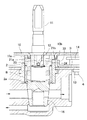
図1を参照して、1はガスコックであり、回動操作軸11を回動操作することにより図外のバーナに送られるガスが増減制御され火力調節することができる。回動操作軸11には水平なピン12が係合し、該ピン12によってカム板2が回動する。該カム板2の近傍には基板13に対して揺動自在に第1レバー部材3と第2レバー部材4とが取り付けられている。第1レバー部材3は基板13の上面に接し、第2レバー部材4は基板13の下面に接するように配設され、枢軸14によって基板13に揺動自在に取り付けられている。また、枢軸14にはトーションばね5が取り付けられている。該トーションばね5の長腕51は第1レバー部材3の縦爪31に係合し、短腕52は第2レバー部材4の縦爪41に係合している。従って、トーションばね5の付勢力により第2レバー部材4の縦爪41は第1レバー部材3の尾端部34に所定の大きさの付勢力で応接される。カム板2が回動して第1レバー部材3のパッド部33がカム板2によって押されると、第1レバー部材3は揺動する。第2レバー部材4はトーションばね5の付勢力によって第1レバー部材3に追従し第2レバー部材4のパッド部42がロッド15を押し込む。該ロッド15は回動操作軸11の回動軸線に対して直角方向に進退自在に保持されており、該ロッド15がガスコック1内に押し込まれると、ガスコック1に内蔵されている図示しない電磁安全弁が強制的に開弁される。尚、6は点火用のスパーカーを作動させるための点火スイッチである。
【0009】
図2を参照して、0度である閉弁位置(止)から115度の位置に設定されている点火位置(点火)まで回動操作軸11を一気に回動すると回動操作軸11は点火位置でそれ以上の回動が禁止されると共に点火スイッチ6がオンされて図示しないガスバーナに点火が行われる。点火が完了すると回動操作軸11から手を離すことにより、回動操作軸11は自動的に95度の位置に設定されている全開位置(全開)まで自動的に一旦戻る。その後は点火位置を越えて150度の位置に設定されているとろ火位置(とろ火)まで回動操作軸11を回動させることができ、該とろ火位置と45度の位置に設定した弱火位置(弱)との間で自在に火力調節を行うことができる。そして、調理終了後は回動操作軸11を閉弁位置にまで戻す。
【0010】
図3を参照して、カム板2にはカム板2を上方から覆う爪板10の爪10a・10bに対して各々対応する斜面21a・21bが形成されている。また、斜面21bの近傍には外側に張り出すカム部22が形成されており、第1レバー部材3のパッド部33に該カム部22が当接する。また、上記ピン12が挿入される一対の縦溝23が形成されている。縦溝23内には回動操作軸11を閉弁位置から点火位置まで回動操作する際ピン12が当接する斜面24が形成されている。また、カム部22を挟んで、閉弁位置における位置決めを行う基準端面25と、点火位置及びとろ火位置における位置決めを行う基準端面26とが形成されている。
【0011】
図4及び図6を参照して、閉弁位置では爪板10の爪10a・10bは共にカム板2の上面に当接している。従って、カム板2を上方に付勢するばね2aの付勢力によってもカム板2は上方に移動することはない。回動操作軸11を点火位置に向かって回動するとカム板2は回動し、両斜面21a・21bは共に爪10a・10bの下方に移動する。すると爪10a・10bの下端はカム板2の上面から離れるが、縦溝23内のピン12は斜面24に押しつけられ斜面24にピン12が係合した状態になっている。このため、カム板2はばね2aによって押し上げられることなく回動し続ける。回動操作軸11を点火位置まで回動すると上記基準端面26がストッパリング8のストッパ部81に当接してそれ以上回動できなくなると共にロッド15が押し込まれ安全弁が強制的に開弁され、更に点火スイッチ6がオンされる。この時ロッド15は安全弁を開ききる位置まで押し込まれると安全弁が邪魔となってそれ以上押し込めなくなる。ところが回動操作軸11は組み付け誤差や加工誤差等によりロッド15がそれ以上押し込めない状態になっても更に第1レバー部材3を揺動させる方向に回動することができる場合がある。ロッド15には第2レバー部材4のパッド部42が当接しているのでロッド15がそれ以上押し込めなくなると第2レバー部材4はそれ以上揺動できなくなる。更に第1レバー部材3を揺動させると、図7に示すように、トーションばね5の付勢力にうち勝って第1レバー部材3のみが揺動し縦爪41は尾端部34から離れる。バーナに点火されたことを確認して回動操作軸11から手を離すと、図5に示すように、ピン12が斜面24から外れながら回動操作軸11が全開位置まで戻る。その際カム板2はピン12との係合が解除されるためばね2aの付勢力により上方に押し上げられ、カム部22は第1レバー部材3のパッド部33に当接しない非点火状態になる。また、第2レバー部材4はロッド15によって押し戻されるが、ロッド15にはトーションばね5によって制限された応力以上の力が作用しないので回動操作軸11に対する操作力を急に解除しても、解除時のショックが大きくならず、従って解除時のショックで安全弁が閉弁してしまうという不具合を回避することができる。このあとは図8に示したようにカム部22が第1レバー部材3のパッド部33に当接しないので、回動操作軸11をとろ火位置と弱位置との間で自由に回動操作することができ、その際回動操作軸11が点火位置を通過しても点火スイッチ6がオンされることはなく、かつロッド15が押し込まれることはない。そして、弱位置から回動操作軸11を閉弁位置に戻す際には爪板10の両爪10a・10bが斜面21a・21bを押し、カム板2を当初の点火可能状態まで押し下げる。
【0012】
ところで、上記実施の形態では全開状態で点火を行い、点火後更に追い込み回動操作することにより火力がとろ火まで減少するようにしたが、例えば図9に示すように、中火状態で点火を行い更に追い込み回動操作をすることにより全開状態になるように構成してもよい。近年最大燃焼量が大きなハイカロリーのガスバーナの使用が増加しているが、ハイカロリーのガスバーナでは中火状態でも十分に点火を行うことができると共に、全開状態で点火を行うと点火音が強くなり、あるいは調理鍋から炎が溢れて使用者が驚くからである。
【0013】
【発明の効果】
以上の説明から明らかなように、本発明は、回動操作軸の軸線に対して直角方向に往復移動するロッドを備えているタイプのガスコックにおいても点火位置を越えて追い込み回動操作することのできる。また、点火完了後急に回動操作軸から手を離しても、安全弁を強制的に開弁させるロッドに一定以上の力が作用していないのでショックで安全弁が閉弁してしまうという不具合がない。
【図面の簡単な説明】
【図1】本発明の一実施の形態の構成を示す図
【図2】回動操作軸の回動範囲を示す図
【図3】カム板の形状を示す斜視図
【図4】点火可能状態にあるカム板を示す図
【図5】非点火状態にあるカム板を示す図
【図6】閉弁位置での平面図
【図7】点火位置での平面図
【図8】追い込み操作時の平面図
【図9】回動操作軸の他の回動範囲を示す図
【符号の説明】
1 ガスコック
2 カム板
3 第1レバー部材
4 第2レバー部材
5 トーションばね
6 点火スイッチ
11 回動操作軸
15 ロッド[0001]
BACKGROUND OF THE INVENTION
The present invention relates to a gas cock that adjusts the amount of gas supplied to a gas burner by rotating a rotation operation shaft and adjusts the heating power, and ignites the gas burner after igniting the gas burner at an ignition position set during the rotation operation. The present invention relates to a gas cock that further drives the turning operation shaft beyond the position and performs the turning operation.
[0002]
[Prior art]
As a conventional gas cock of this type, for example, according to Japanese Utility Model Publication No. 4-24310, the valve closing position is set to 0 degree, and the rotating operation shaft is rotated to the ignition position set to a position of 115 degrees to ignite the gas burner. After turning the rotating operation shaft to the fully open position at 95 degrees, the heating power is adjusted between the low fire position set at 150 degrees and the weak position set at 45 degrees. Things are known. The gas cock described in the publication has a built-in safety valve that is adsorbed and held by the thermoelectromotive force of a thermocouple heated by a burner flame. Therefore, at the ignition position, the rod that reciprocates along the direction of the axis of the rotation operation shaft is moved in conjunction with the rotation operation of the rotation operation shaft, and the safety valve is forced by the rod until the flame condition is stabilized. The valve is kept open. In the type of gas cock that can be driven and rotated beyond the ignition position, when the burner is ignited at the ignition position, the rod does not force the safety valve to open again during the subsequent rotation operation. When power is released, the rod is retracted in a direction away from the safety valve.
[0003]
[Problems to be solved by the invention]
In the gas cock described in the above publication, a rod is disposed along the axis of the rotation operation shaft, and the safety valve is attached so as to be positioned on the axis of the rotation operation shaft. In this type of gas cock, there is a gas cock configured to reciprocate in the direction perpendicular to the axis of the rotation operation shaft because the length of the rotation operation shaft in the axial direction becomes long. This is provided with a cam that rotates together with the rotation operation shaft, and a lever that is pivotally supported at a substantially central portion. When the rotation operation shaft is rotated to the ignition position, the cam pushes one end of the lever and swings the lever. The rod is pushed at the other end of the lever. Therefore, the mechanism described in the above publication cannot be applied to the type of gas cock provided with a rod that can reciprocate in a direction perpendicular to the axis of the rotation operation shaft.
[0004]
In view of the above problems, an object of the present invention is to provide a gas cock that can be driven in even if it includes a rod that reciprocates in a direction perpendicular to the axis of the rotation operation shaft.
[0005]
[Means for Solving the Problems]
The present invention in order to solve the above problems, a cam plate for rotation with rotation operating shaft for thermal power adjusting, pushed by the cam plate when the rotates the rotating operating shaft to the ignition position from the closed position A gas cock that forcibly opens a safety valve at the tip of the rod, and a lever portion that swings and a rod that is pushed in a direction perpendicular to the axis of the rotation operation shaft by swinging the lever portion, sets the intermediate to the ignition position of thermal adjustment range of the rotary operation shaft along the cam plate rotating axis, and a non-ignition state not engaged with ignitable state and a lever portion that engages the lever The cam plate is held in an ignitable state and the rotational operation force on the rotational operation shaft is released when the rotational operation shaft is rotated from the closed position to the ignition position. Cam plate moving machine that moves cam plate to non-ignition state The provided, when releasing the rotational operation force, the rotational operation shaft is not moved axially, in a non-ignition state cam plate which moves in the axial direction by the cam plate moving mechanism, the rotational operation in this state The cam plate does not contact the lever portion even when the shaft is rotated .
[0006]
When the pivoting operation shaft is pivoted from the valve closing position to the ignition position, the cam plate is in an ignitable state, so when the cam plate pushes the lever portion, the lever portion swings and the rod is pushed in to open the safety valve. The When the ignition operation is completed, the cam plate is moved to the non-ignition state by the action of the cam plate moving mechanism in order to release the rotary operation force applied to the rotary operation shaft. Then, since the cam plate is not engaged with the lever portion, the rod is not pushed again during the heating power adjustment even if the driving operation is performed.
[0007]
By the way, when the lever portion is constituted by a single lever member, the rotational operation force is transmitted from the lever portion to the safety valve as it is via the rod. When the turning operation force is large, the tip of the rod strongly presses the safety valve. If the cam plate suddenly moves to the non-ignition state in this state, the force acting on the safety valve from the rod is suddenly released, and the safety valve may be closed due to springback or impact. In this case, the lever portion includes a first lever member that abuts on the cam plate and a second lever member that abuts on the rod, and when the rod is pushed in, the lever moves from the first lever to the second lever. It is only necessary to provide a limiting mechanism that limits the action of a force of a predetermined magnitude or more. With this configuration, even if a large force is applied to the first lever member from the cam plate, a force greater than a predetermined magnitude is applied from the first lever member to the second lever member by the limiting mechanism. Does not work.
[0008]
DETAILED DESCRIPTION OF THE INVENTION
Referring to FIG. 1, reference numeral 1 denotes a gas cock. By turning the
[0009]
Referring to FIG. 2, when the
[0010]
Referring to FIG. 3, the
[0011]
4 and 6, both the
[0012]
By the way, in the above embodiment, ignition is performed in the fully open state, and further, after the ignition, further driving and turning operation is performed so that the thermal power is reduced to the melting fire. For example, as shown in FIG. Further, it may be configured to be in a fully open state by performing a driving rotation operation. In recent years, the use of high-calorie gas burners with a large maximum combustion amount has increased, but high-calorie gas burners can ignite sufficiently even in medium-fire conditions, and the ignition sound becomes stronger when ignited in a fully-open condition. Or because the fire overflows from the cooking pot and the user is surprised.
[0013]
【The invention's effect】
As is apparent from the above description, the present invention is capable of performing a turning rotation operation beyond the ignition position even in a gas cock having a rod that reciprocates in a direction perpendicular to the axis of the rotation operation shaft. it can. In addition, even if you release your hand from the rotating operation shaft suddenly after ignition is complete, there is a problem that the safety valve closes due to a shock because a force exceeding a certain level does not act on the rod that forcibly opens the safety valve. Absent.
[Brief description of the drawings]
FIG. 1 is a diagram showing a configuration of an embodiment of the present invention. FIG. 2 is a diagram showing a rotation range of a rotation operation shaft. FIG. 3 is a perspective view showing a shape of a cam plate. Fig. 5 shows the cam plate in a non-ignition state. Fig. 6 shows a plan view at the valve closing position. Fig. 7 shows a plan view at the ignition position. Plan view [Fig. 9] Diagram showing another rotation range of the rotation operation shaft [Explanation of symbols]
DESCRIPTION OF SYMBOLS 1
Claims (2)
Priority Applications (4)
| Application Number | Priority Date | Filing Date | Title |
|---|---|---|---|
| JP27398899A JP3678954B2 (en) | 1999-09-28 | 1999-09-28 | Gas cock |
| TW089113419A TW480323B (en) | 1999-09-28 | 2000-07-06 | Gas cock |
| KR10-2000-0051014A KR100376819B1 (en) | 1999-09-28 | 2000-08-31 | A gas cock |
| CNB001317164A CN1234997C (en) | 1999-09-28 | 2000-09-27 | Gas valve |
Applications Claiming Priority (1)
| Application Number | Priority Date | Filing Date | Title |
|---|---|---|---|
| JP27398899A JP3678954B2 (en) | 1999-09-28 | 1999-09-28 | Gas cock |
Publications (2)
| Publication Number | Publication Date |
|---|---|
| JP2001099422A JP2001099422A (en) | 2001-04-13 |
| JP3678954B2 true JP3678954B2 (en) | 2005-08-03 |
Family
ID=17535386
Family Applications (1)
| Application Number | Title | Priority Date | Filing Date |
|---|---|---|---|
| JP27398899A Expired - Fee Related JP3678954B2 (en) | 1999-09-28 | 1999-09-28 | Gas cock |
Country Status (4)
| Country | Link |
|---|---|
| JP (1) | JP3678954B2 (en) |
| KR (1) | KR100376819B1 (en) |
| CN (1) | CN1234997C (en) |
| TW (1) | TW480323B (en) |
Cited By (1)
| Publication number | Priority date | Publication date | Assignee | Title |
|---|---|---|---|---|
| JP2008089145A (en) * | 2006-10-04 | 2008-04-17 | Harman Pro:Kk | Rotation operative gas equipment cock |
Families Citing this family (12)
| Publication number | Priority date | Publication date | Assignee | Title |
|---|---|---|---|---|
| JP2002188811A (en) * | 2000-12-20 | 2002-07-05 | Rinnai Corp | Rotary gas valve device |
| JP4536035B2 (en) * | 2006-06-12 | 2010-09-01 | リンナイ株式会社 | Thermal power control device |
| JP5208235B2 (en) * | 2011-03-01 | 2013-06-12 | リンナイ株式会社 | Gas stove device |
| KR101405134B1 (en) * | 2013-03-28 | 2014-06-10 | 린나이코리아 주식회사 | Gas valve for cook-top type gas burner |
| TWI571601B (en) * | 2014-05-07 | 2017-02-21 | Rinnai Kk | Gas cocks (c) |
| TWI576543B (en) * | 2014-05-07 | 2017-04-01 | Rinnai Kk | Gas cocks (a) |
| CN105299309B (en) * | 2014-06-13 | 2019-02-12 | 林内株式会社 | Gas cock |
| CN106195417B (en) * | 2016-08-05 | 2018-08-07 | 宁波方太厨具有限公司 | A kind of gas stove valve |
| CN106122526B (en) * | 2016-08-05 | 2018-10-02 | 宁波方太厨具有限公司 | Gas stove valve |
| KR200490617Y1 (en) | 2018-02-12 | 2019-12-09 | (주)이에스 | Cover with hole of convector for Heating and Cooling Device, and Assembly with the cover |
| JP7111542B2 (en) * | 2018-07-23 | 2022-08-02 | リンナイ株式会社 | gas cock |
| CN115059772B (en) * | 2022-06-10 | 2024-09-03 | 温州大学 | Fireproof sealing rotary ball valve and assembly method thereof |
-
1999
- 1999-09-28 JP JP27398899A patent/JP3678954B2/en not_active Expired - Fee Related
-
2000
- 2000-07-06 TW TW089113419A patent/TW480323B/en not_active IP Right Cessation
- 2000-08-31 KR KR10-2000-0051014A patent/KR100376819B1/en not_active IP Right Cessation
- 2000-09-27 CN CNB001317164A patent/CN1234997C/en not_active Expired - Fee Related
Cited By (1)
| Publication number | Priority date | Publication date | Assignee | Title |
|---|---|---|---|---|
| JP2008089145A (en) * | 2006-10-04 | 2008-04-17 | Harman Pro:Kk | Rotation operative gas equipment cock |
Also Published As
| Publication number | Publication date |
|---|---|
| TW480323B (en) | 2002-03-21 |
| KR100376819B1 (en) | 2003-03-19 |
| JP2001099422A (en) | 2001-04-13 |
| CN1234997C (en) | 2006-01-04 |
| CN1289907A (en) | 2001-04-04 |
| KR20010050286A (en) | 2001-06-15 |
Similar Documents
| Publication | Publication Date | Title |
|---|---|---|
| JP3678954B2 (en) | Gas cock | |
| JP3660164B2 (en) | Gas cock | |
| JP3609652B2 (en) | Ignition mechanism | |
| JP3066787B2 (en) | Gas appliance igniter | |
| JPH0330703Y2 (en) | ||
| JP3793859B2 (en) | Gas cock for automatic ignition | |
| JP3770672B2 (en) | Gas combustion equipment | |
| JPH0740883Y2 (en) | Gas stove temperature sensor actuation device | |
| JP4877824B2 (en) | Thermal power control device | |
| JPH08303774A (en) | Fire force adjusting mechanism at ignition of gas apparatus | |
| JP3678934B2 (en) | Thermal power control device | |
| JPH08285269A (en) | Combustion-adjusting device for gas appliance | |
| JP3580465B2 (en) | Gas stove gas control device | |
| JP3128470B2 (en) | Gas equipment combustion regulator | |
| JPH08285279A (en) | Combustion adjusting device for gas equipment | |
| JPH025245Y2 (en) | ||
| JPH10169992A (en) | Gas amount controller for gas combustor | |
| JP3526116B2 (en) | Gas stove combustion amount adjustment device | |
| JPS5916680Y2 (en) | Gas rice cooker safety device | |
| JP3876454B2 (en) | Gas appliance plug device | |
| JP3128469B2 (en) | Thermal power adjustment mechanism for ignition of gas equipment | |
| JP2756917B2 (en) | Gas appliance thermal power control device | |
| JPH04129645U (en) | Gas amount adjustment device | |
| JP3524284B2 (en) | Gas cock | |
| JPH0221687Y2 (en) |
Legal Events
| Date | Code | Title | Description |
|---|---|---|---|
| A977 | Report on retrieval |
Free format text: JAPANESE INTERMEDIATE CODE: A971007 Effective date: 20040813 |
|
| A131 | Notification of reasons for refusal |
Free format text: JAPANESE INTERMEDIATE CODE: A131 Effective date: 20040914 |
|
| A521 | Written amendment |
Free format text: JAPANESE INTERMEDIATE CODE: A523 Effective date: 20041111 |
|
| TRDD | Decision of grant or rejection written | ||
| A01 | Written decision to grant a patent or to grant a registration (utility model) |
Free format text: JAPANESE INTERMEDIATE CODE: A01 Effective date: 20050412 |
|
| A61 | First payment of annual fees (during grant procedure) |
Free format text: JAPANESE INTERMEDIATE CODE: A61 Effective date: 20050511 |
|
| R150 | Certificate of patent or registration of utility model |
Free format text: JAPANESE INTERMEDIATE CODE: R150 |
|
| FPAY | Renewal fee payment (event date is renewal date of database) |
Free format text: PAYMENT UNTIL: 20090520 Year of fee payment: 4 |
|
| FPAY | Renewal fee payment (event date is renewal date of database) |
Free format text: PAYMENT UNTIL: 20100520 Year of fee payment: 5 |
|
| FPAY | Renewal fee payment (event date is renewal date of database) |
Free format text: PAYMENT UNTIL: 20110520 Year of fee payment: 6 |
|
| FPAY | Renewal fee payment (event date is renewal date of database) |
Free format text: PAYMENT UNTIL: 20110520 Year of fee payment: 6 |
|
| FPAY | Renewal fee payment (event date is renewal date of database) |
Free format text: PAYMENT UNTIL: 20120520 Year of fee payment: 7 |
|
| FPAY | Renewal fee payment (event date is renewal date of database) |
Free format text: PAYMENT UNTIL: 20120520 Year of fee payment: 7 |
|
| FPAY | Renewal fee payment (event date is renewal date of database) |
Free format text: PAYMENT UNTIL: 20130520 Year of fee payment: 8 |
|
| FPAY | Renewal fee payment (event date is renewal date of database) |
Free format text: PAYMENT UNTIL: 20140520 Year of fee payment: 9 |
|
| R250 | Receipt of annual fees |
Free format text: JAPANESE INTERMEDIATE CODE: R250 |
|
| R250 | Receipt of annual fees |
Free format text: JAPANESE INTERMEDIATE CODE: R250 |
|
| LAPS | Cancellation because of no payment of annual fees |