JP3678371B2 - Trimmer capacitor - Google Patents
Trimmer capacitor Download PDFInfo
- Publication number
- JP3678371B2 JP3678371B2 JP03882195A JP3882195A JP3678371B2 JP 3678371 B2 JP3678371 B2 JP 3678371B2 JP 03882195 A JP03882195 A JP 03882195A JP 3882195 A JP3882195 A JP 3882195A JP 3678371 B2 JP3678371 B2 JP 3678371B2
- Authority
- JP
- Japan
- Prior art keywords
- stator
- rotor
- electrode
- substrate
- stator substrate
- Prior art date
- Legal status (The legal status is an assumption and is not a legal conclusion. Google has not performed a legal analysis and makes no representation as to the accuracy of the status listed.)
- Expired - Fee Related
Links
Images


Description
【0001】
【産業上の利用分野】
本発明はトリマーコンデンサに関するものであり、特にステータ電極の位置を安定させることができるトリマーコンデンサに関するものである。
【0002】
【従来の技術】
一般に、オープン型トリマーコンデンサは、図7、図8に示すように、ステータ基板61、誘電体ロータ62、調整ピン63、ロータ金具64とから構成されていた。
【0003】
ステータ基板61は、その表面に馬蹄形状のステータ電極61aが埋設されており、ステータ基板61の長手方向の一方端面にはステータ電極61aと連結するステータ端子61bが夫々形成され、また、ステータ基板61の略中央部分には調整ピン63のピン部63bが貫通する貫通穴61cが形成されている。
【0004】
誘電体ロータ62は、誘電体磁器からなり、内部に半円形状のロータ電極62aが形成され、さらにステータ基板61同様に調整ピン63のピン部63bが貫通する貫通穴62bが形成されている。尚、ロータ62の貫通穴62bの内壁にはロータ電極62aと接続する導体膜62cが形成されている。
【0005】
調整ピン63は、金属部材などからなり、調整溝63cが形成された円板状のヘッド部63aと、該ヘッド部63aの底面から垂下するピン部63bとから成っている。
【0006】
ロータ金具64は、バネ部64aとロータ端子64bとから成る。バネ部64aは、その略中央部分に貫通穴64cを有し、ステータ基板61の裏面に配置され、ロー端子64bはステータ基板61の他方端面に配置される。
【0007】
そして、上述の各部品の組立においては、ステータ基板61の表面側に、誘電体ロータ62、ステータ基板61の裏面側にロータ金具64を夫々配置して、調整ピン63のピン部63bを、誘電体ロータ62の貫通穴62b、ステータ基板61の貫通穴61c、ロータ金具64のバネ部64aの貫通穴64cを挿通し、バネ部64aの貫通穴64cから露出したピン部63bの先端を加締め処理していた。
【0008】
尚、調整ピン63と誘電体ロータ62とは、少なくとも貫通穴62b内に半田や導電性樹脂などの導電性接着材が充填・接合されており、これにより、調整ピン63と誘電体ロータ62とが共動し、且つ誘電体ロータ63の導体膜62cと調整ピン63とが導通されるようになっている。
【0009】
これにより、ステータ電極61aとロータ電極62aとの対向面積、及びその間に存在する誘電体ロータ62の誘電体磁器の誘電率によって、所定容量が発生し、これが、ステータ端子61bと、ロータ端子64b(ロータ電極62a−導体膜62c−導電性接着材−調整ピン63−ロータ金具64が互いに導通している)との間で所定容量が導出されることになる。
【0010】
上述トリマーコンデンサにおいて、ステータ電極61a及びステータ端子61bとから成るステータ金具は、樹脂の射出成型によって形成されるステータ基板に埋設一体化され、ステータ電極61aがステータ基板61の表面に露出し、ステータ端子62bがステータ基板61の長手方向の一方端面に露出する。
【0011】
ここで、重要なことは、ステータ電極61aの表面がステータ基板61と同一平面とすることで必要がある。即ち、ステータ電極61aの上面には、誘電体ロータ61が密着するように配置されるが、ステータ電極61aの表面がステータ基板61の表面が異なってしてまうと、誘電体ロータ62の回動が安定せず、また、ステータ電極61aとロータ電極61aとの間隔が変動したり、ステータ電極61aと誘電体ロータ62との間で空気の層が発生したりして、安定した特性が導出できなくなる。
【0012】
ステータ電極61aの位置ずれが起こる原因は、所定金型の中空部にステータ金具を所定位置が配置し、この中空部に樹脂を充填してステータ基板61を形成するが、この時、ステータ金具のステータ端子61b側が金型で固定されるものの、ステータ電極61a側が自由端状態となるため発生する。
【0013】
このようなステータ電極61aの位置ずれを防止するために、ステータ電極61aの外周部にアンカー部61dを設けていた(特開平6−20872号)。
【0014】
このアンカー部61dは、ステータ基板61において、ステータ電極61aの外周部からステータ基板61内部に埋設され、ステータ基板61の裏面側に延出されていた。
【0015】
【発明が解決しようとする課題】
しかしながら、アンカー部61dが露出するステータ基板61の裏面側は、ロータ金具64が配置され、さらに、プリント配線基板上に実装した場合、はんたなどが付着する部位であるため、
▲1▼アンカー部61dの露出部分とロータ金具64とが接触してしまう
▲2▼仮にアンカー部61dの露出部分とロータ金具64との間が非接触状態であっても、プリント配線基板への実装時に、半田架橋が発生してしまう
などの問題があった。
【0016】
即ち、アンカー部61d(ステータ電極61a側)とロータ金具64(ロータ電極62a側)とが電気的に短絡してしまい、その間で得られた所定容量成分が無視されてしまい、トリマーコンデンサとして全く機能しなくなる。
【0017】
本発明は上述の問題点に鑑み案出されてたものであり、その目的は、ステータ電極をステータ基板の表面に安定的に配置することができるとともに、ステータ端子とロータ端子との短絡が一切発生しないトリマーコンデンサを提供するものである。
【0018】
【問題点を解決するための手段】
本発明は、上面に形成されるステータ電極及び該ステータ電極から延びるステータ端子を有するステータ基板と、前記ステータ基板の上面に配置しロータ電極を有する回動可能な誘電体ロータと、前記ステータ基板の下面に配置しロータ端子及びバネ部を有するロータ金具と、前記ステータ基板、誘電体ロータ及びロータ金具に夫々形成されている貫通孔に挿通して加締め処理する調整ピンと、を有して成り、前記ステータ電極の外周部に、前記ステータ基板に埋設され、且つステータ基板の側面でステータ基板下面から離間した位置に延出するアンカー部を設けたトリマーコンデンサである。
【0019】
さらに好ましくは、前記ステータ基板の側面部分に窪み部を形成するとともに、この窪み部内にアンカー部を露出させたものである。
【0020】
【作用】
本発明によれば、ステータ基板を形成する金型の中空部において、ステータ金具、特にステータ電極側を位置決めするためのアンカー部の先端が、金型の中空部内の側面に接触した状態となる。
【0021】
したがって、金型内に樹脂の充填しても、アンカー部の先端と金型の側面との接触により、ステータ電極の沈下を防止することができ、ステータ電極を所定位置で安定的に位置決めすることができる。
【0022】
これにより、ステータ電極の表面がステータ基板の表面と同一平面とすることができ、容量特性の変動を起こしたりや誘電体ロータの回動に悪影響を与えたりすることが一切ない。
【0023】
また、アンカー部はステータ基板の側面側から露出することになるため、十才のように基板の裏面に配置されるロータ金具やプリント配線基板への半田接合を行っても、ステータ端子とロータ端子との短絡を一切起させない。
【0024】
また、ステータ基板の側面に窪み部を形成するとともに、この窪み部内でアンカー部の先端が露出するようにすれば、実質的にステータ基板の側面からアンカー部が突出しないため、例えばトリマーコンデンサを作業工程時の搬送時、プリント配線基板の実装時などのチャッキングなどを安定して行うことができる。
【0025】
【実施例】
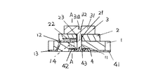
以下、本発明のトリマーコンデンサを図面に基いて詳説する。図1は本発明のトリマーコンデンサの縦断面図であり、図2は図1中のA−A線横断面図である。
【0026】
トリマーコンデンサは、ステータ基板1と、誘電体ロータ2と、調整ピン3と、ロータ金具4とから主に構成されている。
【0027】
ステータ基板1は、樹脂製の概ね直方体であり、ステータ基板1の略中央部分には調整ピン3のピン部32が貫挿する貫通穴11が形成されている。また、ステータ基板1にはスーテタ電極12とステータ端子13とからなるステータ金具が埋設されている。ステータ金具の一端であるステータ端子13は、ステータ基板1の一端面の底面付近から延出しており、ステータ金具の他端であるステータ電極12は概略馬蹄形状を成して、ステータ基板1の表面に露出している。
【0028】
このように複雑な形状で、且つステータ金具が埋設されたステータ基板1は、樹脂の射出成型によって形成される。
【0029】
誘電体ロータ2は、所定誘電体材料の円板状を成し、その中央部部分には調整ピン3のピン部32が貫挿する貫通穴21が形成されている。また、誘電体ロータ2の内部には半円形状のロータ電極22が形成されている。このロータ電極22の一部は、貫通穴21に現れており、貫通穴21の内壁にはロータ電極22と接続するロータ引出導体膜23が形成されている。このような誘電体ロータ2は、誘電体グリーンシートと、ロータ電極22となる所定金属導体膜のパターンが印刷された誘電体グリーンシートとを積層して、その積層体に貫通穴21となる穴を形成し、ロータ引出導体膜23となる導体膜を印刷し、焼成処理して形成される。
【0030】
調整ピン3は、金属部材からなり、表面に調整溝31aが形成されたヘッド部31と、該ヘッド部から垂下するピン部32とから構成されている。このピン部32は、誘電体ロータ2の貫通穴21、ステータ基板1の貫通穴11、さらに後述のロータ金具のバネ部42の貫通穴43に挿通され、その先端部が加締め処理される。
【0031】
ロータ金具4は、弾性を有する金属部材からなり、その一端にロータ端子41が、他端にバネ部42が形成されている。ロータ端子41は、ステータ端子13が形成された端面と対向する端面に延出されている。バネ部42は、例えば円形状となっており、その中央部分には、調整ピン3のピン部32が挿通される貫通穴43が形成されている。
【0032】
このような構成から成るトリマーコンデンサは、ステータ基板1の表面に、誘電体ロータ2、裏面にロータ金具4を夫々配置して、続いて、調整ピン3のピン部32を誘電体ロータ2の貫通穴21、ステータ基板1の貫通穴11、ロータ金具4のバネ部42の貫通穴43を挿通させて、該貫通穴43から突出した先端部を加締め処理を行う。
【0033】
尚、調整ピン3と誘電体ロータ2とは、半田や導電性樹脂などの導電性接着材を介して接着固定する。これにより、ステータ基板1上に、誘電体ロータ2、調整ピン3とが、調整ピン3の回動操作に互いに連動するとともに、ロータ電極22と調整ピン3とが電気的に導通することになる。
【0034】
このようにトリマーコンデンサは、調整ピン3の調整溝31aにドライバーなどを挿入して所定量回動することにより、ステータ端子13とロータ端子41との間で所定容量が得られる。即ち、誘電体ロータ2の回動により、ステータ電極12と誘電体ロータ2の内部のロータ電極22の対向面積が変動し、この対向面積及びその間に存在する誘電体磁器の誘電率に対応する容量がステータ端子13とロータ端子41(ロータ電極22−導電膜23−調整ピン3ーロータ金具4に夫々導通している)との間から導出する。
【0035】
本発明の特徴的なことは、ステータ電極12の外周部には、ステータ基板1内に埋設され、且つその先端がステータ基板1の側面から露出するアンカー部14、14が設けられていることである。
【0036】
この種のステータ基板1は、図3、図4に示すように、上下に2つに分割され、内部にステータ基板の形状に対応した中空部が形成された金型15(15a、15b)を用い、この金型15の中空部内にステータ金具を固定した状態で樹脂の射出成型によって形成される。金型15には、ステータ金具の一方端面から延出するステータ端子13が形成されるように、下側金型15aには切り欠き部16aが形成させており、また上側金型15bには、この切り欠き部16aにステータ金具を介して嵌合される突出部16bが形成されている。
【0037】
また、ステータ基板1の側面の厚み方向の中央部に相当する、上下側金型15a、15bとの接合部分には、アンカー部14、14の先端と当接する楔状凹部17a、17aが形成されている。尚、この楔状凹部17aは、上下両金型15a、15bに形成してもよいし、何れか一方の金型、例えば下側金型15aにのみ形成しても構わない。
【0038】
このように金型15を用いることによって、図4に示すように金型15の中空部内でステータ金具を非常に安定的に位置決めすることができる。例えば、ステータ金具の一端側であるステータ端子13側は、切り欠き部16aと突出部16bとに挟持・固定され、また、ステータ金具の他端側であるステータ電極12側は、楔状凹部17aに先端が嵌合されたアンカー部14、14によって固定される。
【0039】
これにより、上述の金型15を用いて樹脂の射出成型によって形成されたステータ基板1においては、ステータ電極12の表面がステータ基板1の表面と同一平面とすることができ、誘電体ロータ2とステータ電極12との接触状態が安定し、所定特性を安定して導出することができる。
【0040】
また、アンカー部14、14の先端部分が、従来のようにステータ基板61の裏面に露出することがないため、ステータ基板1の裏面にロータ金具4を配置しても、このロータ金具4との接触が一切起こらず、またプリント配線基板に半田接合しても、アンカー部14、14とロータ金具との半田架橋も一切起こることがなく、ロータ金具の形状やその取付などが制約されることがない。
【0041】
図5は、本発明の別のトリマーコンデンサの外観斜視図である。
【0042】
この実施例では、ステータ基板1の側面に、基板の厚み方向に延びる窪み部18を形成して、この窪み部18内にアンカー部14、14の先端が配置されている。
【0043】
このような構造を達成するための金型として、図6に示すように、ステータ基板の側面部分に相当する中空部側面に、凸条19を形成して、この凸条19の接合面にアンカー部14、14を嵌合する楔状凹部17bを形成する。
【0044】
これにより、アンカー部14の先端は、ステータ基板1の側面から凹んだ窪み部18に存在することになり、その先端がステータ基板1の側面から実質的に突出することがない構造となる。
【0045】
従って、このようなトリマーコンデンサを、各製造工程中において、また、プリント配線基板上に実装するにあたり、ステータ基板1の側面を用いてチャッキングを行っても、アンカー部14、14の先端がチャッキングの障害になることが一切なく、取り扱いに優れたトリマーコンデンサとなる。
【0046】
尚、図5の窪み部18は、ステータ基板1の側面厚み方向に形成されているが、樹脂の射出成型用金型の形状を変化させることによって、ステータ基板の厚みの半分の長さを有する窪み部とすることもでき、また、ステータ基板の側面に局部的に形成することもできる。
【0047】
【発明の効果】
以上、本発明のトリマーコンデンサは、ステータ電極の外周からステータ基板の側面に露出するアンカー部をステータ基板に埋設したため、ステータ基板の製造中に、特に樹脂の射出成型用金型の中空部内でステータ電極が位置ずれすることがないので、ステータ電極をステータ基板の表面に安定的に形成することができる。
【0048】
また、このアンカー部がステータ基板の側面に露出するため、ステータ基板の裏面側においては何等影響を与えない。即ち、従来のようにロータ金具とアンカー部との接触、プリント配線基板への実装時の半田の架橋による短絡などが一切なく、特性不良を発生しない優れたトリマーコンデンサとなる。
【0049】
さらに、ステータ基板の側面に窪み部を形成し、この窪み部内にアンカー部を露出させることによって、ステータ基板の側面を用いて搬送、実装などのチャッキングが非常に信頼性高く行えることになる。
【図面の簡単な説明】
【図1】本発明のトリマーコンデンサの縦断面図である。
【図2】図1のA−A線の横断面図である。
【図3】本発明のトリマーコンデンサのステータ基板を形成する際に用いる金型の分解斜視である。
【図4】図3の金型において、ステータ金具を配置した状態の断面図である。
【図5】本発明の別のトリマーコンデンサの外観斜視図である。
【図6】図5に示すトリマーコンデンサのステータ基板を形成する際に用いる金型の分解斜視である。
【図7】従来のトリマーコンデンサの縦断面図である。
【図8】図7のB−B線のの横断面図である。
【符号の説明】
1・・・・・ステータ基板
11・・・・貫通穴
12・・・・ステータ電極
13・・・・ステータ端子
14・・・・アンカー部
2・・・・・・誘電体ロータ
21・・・・貫通穴
22・・・・ロータ電極
3・・・・・調整ピン
31・・・・・ヘッド部
32・・・・・ピン部
4・・・・・ロータ金具
41・・・・・ロータ端子
42・・・・・ バネ部[0001]
[Industrial application fields]
The present invention relates to a trimmer capacitor, and more particularly to a trimmer capacitor that can stabilize the position of a stator electrode.
[0002]
[Prior art]
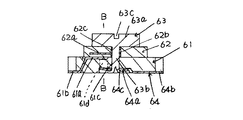
In general, as shown in FIGS. 7 and 8, the open trimmer capacitor is composed of a
[0003]
The
[0004]
The
[0005]
The
[0006]
The
[0007]
In the assembly of the components described above, the
[0008]
The
[0009]
Thus, a predetermined capacity is generated by the facing area between the stator electrode 61a and the rotor electrode 62a and the dielectric constant of the dielectric ceramic of the
[0010]
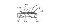
In the above-described trimmer capacitor, a stator fitting including the stator electrode 61a and the stator terminal 61b is embedded and integrated in a stator substrate formed by resin injection molding, and the stator electrode 61a is exposed on the surface of the
[0011]
Here, what is important is that the surface of the stator electrode 61 a be flush with the
[0012]
The cause of the displacement of the stator electrode 61a is that a predetermined position of the stator fitting is placed in the hollow portion of the predetermined mold, and the
[0013]
In order to prevent such displacement of the stator electrode 61a, an
[0014]
The
[0015]
[Problems to be solved by the invention]
However, since the
(1) The exposed portion of the
[0016]
That is, the
[0017]
The present invention has been devised in view of the above-described problems, and its purpose is to stably arrange the stator electrodes on the surface of the stator substrate and to prevent any short circuit between the stator terminals and the rotor terminals. A trimmer capacitor that does not occur is provided.
[0018]
[Means for solving problems]
The present invention provides a stator substrate having a stator electrode formed on the upper surface and a stator terminal extending from the stator electrode, a rotatable dielectric rotor having a rotor electrode disposed on the upper surface of the stator substrate, and the stator substrate A rotor fitting having a rotor terminal and a spring portion disposed on the lower surface, and an adjustment pin that is inserted into through holes formed in the stator substrate, the dielectric rotor, and the rotor fitting, respectively, and is caulked. The trimmer capacitor is provided with an anchor portion embedded in the outer periphery of the stator electrode and extending to a position spaced apart from the lower surface of the stator substrate on the side surface of the stator substrate .
[0019]
More preferably, a recess is formed in the side surface portion of the stator substrate, and the anchor is exposed in the recess.
[0020]
[Action]
According to the present invention, in the hollow portion of the mold that forms the stator substrate, the tip of the anchor member for positioning the stator bracket, particularly the stator electrode side, is in contact with the side surface in the hollow portion of the mold.
[0021]
Therefore, even if the mold is filled with resin, the contact between the tip of the anchor portion and the side surface of the mold can prevent the stator electrode from sinking, and the stator electrode can be stably positioned at a predetermined position. Can do.
[0022]
As a result, the surface of the stator electrode can be flush with the surface of the stator substrate, and there is no change in capacity characteristics or adversely affecting the rotation of the dielectric rotor.
[0023]
In addition, since the anchor portion is exposed from the side surface side of the stator substrate, the stator terminal and the rotor terminal can be used even when soldering to a rotor fitting or printed wiring board arranged on the back surface of the substrate as in the case of ten years old. Do not cause any short circuit.
[0024]
Also, if a recess is formed on the side surface of the stator substrate and the tip of the anchor portion is exposed in the recess, the anchor portion does not substantially protrude from the side surface of the stator substrate. Chucking and the like can be stably performed during conveyance during the process and mounting of the printed wiring board.
[0025]
【Example】
The trimmer capacitor of the present invention will be described in detail below with reference to the drawings. FIG. 1 is a longitudinal sectional view of the trimmer capacitor of the present invention, and FIG. 2 is a transverse sectional view taken along line AA in FIG.
[0026]
The trimmer capacitor mainly includes a stator substrate 1, a
[0027]
The stator substrate 1 is a substantially rectangular parallelepiped made of resin, and a through hole 11 through which the
[0028]
The stator substrate 1 having such a complicated shape and having the stator bracket embedded therein is formed by resin injection molding.
[0029]
The
[0030]
The
[0031]
The rotor fitting 4 is made of an elastic metal member, and has a
[0032]
In the trimmer capacitor having such a configuration, the
[0033]
The
[0034]
Thus, the trimmer capacitor can obtain a predetermined capacity between the
[0035]
A characteristic of the present invention is that the outer peripheral portion of the
[0036]
As shown in FIGS. 3 and 4, this type of stator substrate 1 includes a mold 15 (15 a, 15 b) that is divided into two vertically and a hollow portion corresponding to the shape of the stator substrate is formed inside. Used, it is formed by resin injection molding in a state where the stator fitting is fixed in the hollow portion of the
[0037]
In addition, wedge-shaped
[0038]
By using the
[0039]
Thereby, in the stator substrate 1 formed by resin injection molding using the
[0040]
Further, since the tip portions of the
[0041]
FIG. 5 is an external perspective view of another trimmer capacitor of the present invention.
[0042]
In this embodiment, a
[0043]
As a mold for achieving such a structure, as shown in FIG. 6, a
[0044]
As a result, the tip of the
[0045]
Therefore, when such a trimmer capacitor is mounted in each manufacturing process or on the printed wiring board, even if chucking is performed using the side surface of the stator substrate 1, the tips of the
[0046]
5 is formed in the thickness direction of the side surface of the stator substrate 1, but has a length that is half the thickness of the stator substrate by changing the shape of the resin injection mold. It can also be a recess, and can also be formed locally on the side of the stator substrate.
[0047]
【The invention's effect】
As described above, in the trimmer capacitor according to the present invention, since the anchor portion exposed from the outer periphery of the stator electrode to the side surface of the stator substrate is embedded in the stator substrate, the stator portion is produced in the hollow portion of the resin injection mold particularly during the production of the stator substrate. Since the electrode is not displaced, the stator electrode can be stably formed on the surface of the stator substrate.
[0048]
Further, since the anchor portion is exposed on the side surface of the stator substrate, there is no influence on the back surface side of the stator substrate. That is, there is no contact between the rotor metal fitting and the anchor portion as in the prior art, and no short circuit due to the bridging of the solder when mounted on the printed wiring board, so that an excellent trimmer capacitor that does not cause poor characteristics is obtained.
[0049]
Further, by forming a recess on the side surface of the stator substrate and exposing the anchor portion in the recess, chucking such as conveyance and mounting can be performed with high reliability using the side surface of the stator substrate.
[Brief description of the drawings]
FIG. 1 is a longitudinal sectional view of a trimmer capacitor of the present invention.
2 is a cross-sectional view taken along line AA in FIG.
FIG. 3 is an exploded perspective view of a mold used when forming a trimmer capacitor stator substrate of the present invention.
4 is a cross-sectional view showing a state in which a stator fitting is arranged in the mold of FIG. 3; FIG.
FIG. 5 is an external perspective view of another trimmer capacitor of the present invention.
6 is an exploded perspective view of a mold used when forming the trimmer capacitor stator substrate shown in FIG. 5;
FIG. 7 is a longitudinal sectional view of a conventional trimmer capacitor.
8 is a cross-sectional view taken along line BB in FIG.
[Explanation of symbols]
DESCRIPTION OF SYMBOLS 1 ... Stator board 11 ... Through-
Claims (2)
前記ステータ電極の外周部に、前記ステータ基板に埋設され、且つステータ基板の側面でステータ基板下面から離間した位置に延出するアンカー部を設けたことを特徴とするトリマーコンデンサ。 A stator substrate having a stator electrode formed on the upper surface and a stator terminal extending from the stator electrode, a rotatable dielectric rotor having a rotor electrode on the upper surface of the stator substrate, and a lower surface of the stator substrate. In a trimmer capacitor comprising: a rotor fitting having a rotor terminal and a spring portion; and an adjustment pin that is inserted into through holes formed in the stator substrate, the dielectric rotor, and the rotor fitting, respectively, and caulked.
A trimmer capacitor, characterized in that an anchor portion embedded in the stator substrate and extending to a position separated from the lower surface of the stator substrate on a side surface of the stator substrate is provided on an outer peripheral portion of the stator electrode.
Priority Applications (1)
| Application Number | Priority Date | Filing Date | Title |
|---|---|---|---|
| JP03882195A JP3678371B2 (en) | 1995-02-27 | 1995-02-27 | Trimmer capacitor |
Applications Claiming Priority (1)
| Application Number | Priority Date | Filing Date | Title |
|---|---|---|---|
| JP03882195A JP3678371B2 (en) | 1995-02-27 | 1995-02-27 | Trimmer capacitor |
Publications (2)
| Publication Number | Publication Date |
|---|---|
| JPH08236398A JPH08236398A (en) | 1996-09-13 |
| JP3678371B2 true JP3678371B2 (en) | 2005-08-03 |
Family
ID=12535928
Family Applications (1)
| Application Number | Title | Priority Date | Filing Date |
|---|---|---|---|
| JP03882195A Expired - Fee Related JP3678371B2 (en) | 1995-02-27 | 1995-02-27 | Trimmer capacitor |
Country Status (1)
| Country | Link |
|---|---|
| JP (1) | JP3678371B2 (en) |
-
1995
- 1995-02-27 JP JP03882195A patent/JP3678371B2/en not_active Expired - Fee Related
Also Published As
| Publication number | Publication date |
|---|---|
| JPH08236398A (en) | 1996-09-13 |
Similar Documents
| Publication | Publication Date | Title |
|---|---|---|
| JP3678371B2 (en) | Trimmer capacitor | |
| JPS6210984Y2 (en) | ||
| JPH0533847B2 (en) | ||
| JPH074763Y2 (en) | Chip fuse | |
| JPH0369106A (en) | Polar electronic part and carrier tape | |
| JP2602758Y2 (en) | Trimmer capacitor | |
| JPS63204611A (en) | Manufacture of solid electrolytic capacitor | |
| JPS6316895B2 (en) | ||
| JPH0236267Y2 (en) | ||
| JP3801949B2 (en) | connector | |
| JP2572664Y2 (en) | Semi-fixed resistor | |
| JPS605563Y2 (en) | variable ceramic capacitor | |
| JPH0236262Y2 (en) | ||
| JPH0198252A (en) | Package for semiconductor | |
| JPS61113223A (en) | Leadless type electrolytic capacitor | |
| JPS5915067Y2 (en) | Feedthrough capacitor | |
| JPH0541522Y2 (en) | ||
| JPH1197276A (en) | Chip-type capacitor | |
| JPS5934991Y2 (en) | variable porcelain capacitor | |
| JPH0741121Y2 (en) | Variable resistor terminal lead-out structure | |
| JPH0740526B2 (en) | Variable resistor | |
| JPH0351965Y2 (en) | ||
| JPS6020916Y2 (en) | Axial lead capacitor | |
| JPH05199059A (en) | Piezoelectric component | |
| JPS61131502A (en) | Electronic compoment |
Legal Events
| Date | Code | Title | Description |
|---|---|---|---|
| A977 | Report on retrieval |
Free format text: JAPANESE INTERMEDIATE CODE: A971007 Effective date: 20040810 |
|
| A131 | Notification of reasons for refusal |
Free format text: JAPANESE INTERMEDIATE CODE: A131 Effective date: 20040824 |
|
| A521 | Written amendment |
Free format text: JAPANESE INTERMEDIATE CODE: A523 Effective date: 20041025 |
|
| TRDD | Decision of grant or rejection written | ||
| A01 | Written decision to grant a patent or to grant a registration (utility model) |
Free format text: JAPANESE INTERMEDIATE CODE: A01 Effective date: 20050506 |
|
| A61 | First payment of annual fees (during grant procedure) |
Free format text: JAPANESE INTERMEDIATE CODE: A61 Effective date: 20050509 |
|
| R150 | Certificate of patent (=grant) or registration of utility model |
Free format text: JAPANESE INTERMEDIATE CODE: R150 |
|
| LAPS | Cancellation because of no payment of annual fees |