JP3677596B2 - Flexible circuit board connector - Google Patents
Flexible circuit board connector Download PDFInfo
- Publication number
- JP3677596B2 JP3677596B2 JP2000325233A JP2000325233A JP3677596B2 JP 3677596 B2 JP3677596 B2 JP 3677596B2 JP 2000325233 A JP2000325233 A JP 2000325233A JP 2000325233 A JP2000325233 A JP 2000325233A JP 3677596 B2 JP3677596 B2 JP 3677596B2
- Authority
- JP
- Japan
- Prior art keywords
- circuit board
- contact
- flexible circuit
- housing
- connector
- Prior art date
- Legal status (The legal status is an assumption and is not a legal conclusion. Google has not performed a legal analysis and makes no representation as to the accuracy of the status listed.)
- Expired - Fee Related
Links
Images


Description
【0001】
【発明の属する技術分野】
本発明は、主として十分な接触力を発揮するバネ性を有してフレキシブル回路基板(Flexible Printed Cricuit/以下、FPCとする)を安定して接続するための小型で低背構造のFPC用コネクタに関する。
【0002】
【従来の技術】
従来、この種のFPC用コネクタに関連する周知技術の一例として、特開平9−82427号公報に開示されたフラットケーブル用コネクタの場合、本体がプリント(配線)基板上に実装接続可能に構成されており、具体的にはフラットケーブルの挿入方向を前後方向として上方が開口されたハウジングと、ハウジングの前方から後方に延びてその先端にフラットケーブルと電気的に接触される接点部が設けられた接触片及びリード端子片を有すると共に、固定片を有してハウジングの前方側から取り付けられる第1のコンタクトと、ハウジングの後方から前方に延びてその先端にフラットケーブルと電気的に接触される接点部が設けられた接触片及びリード端子片を有すると共に、固定片を有してハウジングの後方側から取り付けられる第2のコンタクトと、第2のコンタクトの弾性支持片に回動自在に支持されてフラットケーブルを押圧固定するレバー部とを備えた構成とすることにより、各コンタクトをハウジングの前後方向に配備することでコネクタ全体の小型化を図っている。
【0003】
又、FPC用コネクタに関連する周知技術の他例として、特開平8−31526号公報に開示されたラッチ付コネクタの場合、本体がプリント(配線)基板上に実装接続可能に構成される点は同じであるが、ここではプラスチック製のハウジングの前後方向に多数本のコンタクトピンを並設されるように装着し、ハウジングの幅方向片側又は両側にプリント基板又はフレキシブル導体に取り付けた補強板により外側に押し広げられ、且つそれらを所定位置まで押し込むと元の位置に戻ってプリント基板又は補強板を圧着して保持するプラスチック製のラッチを設け、更に、ラッチに加えられる接圧を受けるためにラッチ自体に設けられる補強具に対し、ラッチ,補強具自体のラッチ,ハウジングに取り付けるための装着部、並びにハウジングをセットするプリント基板に固定される支持部を形成した構成とすることにより、ラッチのクリープ変形によるプリント基板及びコンタクトピンの接触不良やプリント基板の挿抜時のラッチの破損を防止した上でコネクタ全体の小型化を図っている。
【0004】
更に、FPC用コネクタに関連する周知技術の別例として、特開平11−54220号公報に開示されたフレキシブル回路板コネクタの場合、本体がプリント(配線)基板上に実装接続可能に構成される点は同じであるが、ここでは接触部が金属板面として形成されてフレキシブル回路板の一面側に接触可能に千鳥配置される複数のコンタクトを収容した絶縁ハウジングに舌片を有する加圧部材を回動可能に設け、加圧部材における開位置でその両側面のポストと弾性係合片とが係合して絶縁ハウジングに対して抜け止めされ、閉位置でポストと弾性係合片との係合が解除されると共に、係止突起と絶縁ハウジングとが係止し、且つ舌片がコンタクトの一部と係合して絶縁ハウジング上に維持されることでフレキシブル回路板をコンタクトに向けて押圧して電気的接続させる際に十分な接触力を与える構成としている。
【0005】
【発明が解決しようとする課題】
上述したプリント(配線)基板との接続及びフレキシブルなフラットケーブルとの接続に供されるコネクタの場合、一般に基本機能の確保のために構造上において要求される必要事項として、安定した接触を得るための接触力を具現するために接触バネ片部のバネ長に或る程度の長さが必要とされること、各コンタクトをハウジングに固定するための圧入片部を確保すること、プリント基板と接地される補強金具としての金属部品を取り付けるためのスペースを確保すること等が挙げられるが、これらの必要事項は昨今要求されるコネクタ全体の小型化や低背化(薄型化)を具現する上での妨げとなっているという問題がある。
【0006】
具体的に言えば、特開平9−82427号公報に開示されたフラットケーブル用コネクタの場合、各コンタクトをハウジングの前後方向に配備することでコネクタ全体の小型化を図っているが、ここでは各コンタクトにおけるプリント基板に対する電気的接続のための脚端子片部がハウジングの両側方向に延びているため、コネクタ全体の外形として安定した接触力を得るための各コンタクトにおける接触バネ片部のバネ長が短くなっており、これによりフラットケーブルに対して安定した接触状態が得られない構造となっているという問題がある。又、ここでのコネクタの場合、各コンタクトにおけるハウジングに固定するための圧入片部を二股に分かれた片部とし、下側又は上側に位置する一方の片部を用いる構造としているため、低背化を具現しようとするとハウジングのモールド厚が薄くなってしまい、これにより機械的強度を十分に確保できなくなってしまうという問題もある。
【0007】
一方、特開平8−31526号公報に開示されたラッチ付コネクタの場合も、各コンタクトをハウジングの前後方向に配備することでコネクタ全体の小型化を図っているが、ここでも各コンタクトにおけるプリント基板に対する電気的接続を行うための脚端子片部にスペースを要してしまい、接触バネ片部のバネ長を確保しようとすると小型化が困難になってしまうという問題がある他、脚端子片部とは反対側の方向にコンタクトと別個にプリント基板固定用の金属部品(コネクタをプリント基板に安定した姿勢で固定させ、同時にフレキシブル導体の接続強度を向上させるためのもの)を取り付ける必要があるため、この金属部品をハウジングに取り付けるためのスペースがコネクタ全体を小型化したり、低背化(薄型化)する上での妨げとなっているという問題がある。
【0008】
他方、特開平11−54220号公報に開示されたフレキシブル回路板コネクタの場合、絶縁ハウジングに舌片を有する加圧部材を回動可能に設けてその閉位置で舌片がフレキシブル回路板をコンタクトに向けて押圧して電気的接続させる際の十分な接触力を与える構成としているが、ここでは加圧部材の舌片がフレキシブル回路板を押圧可能に回動させるためのスペースを背高方向に設ける必要があり、背高方向に或る程度の寸法を確保する必要があるため、この加圧部材の舌片を回動可能にするためのスペースがコネクタ全体を小型化したり、低背化(薄型化)する上での妨げとなっているという問題がある。
【0009】
本発明は、このような問題点を解決すべくなされたもので、その技術的課題は、十分な接触力を発揮するバネ性を有する小型で低背構造の容易に製造し得るFPC用コネクタを提供することにある。
【0010】
【課題を解決するための手段】
本発明によれば、一軸方向に沿って所定の間隔で該一軸方向と垂直な他軸方向に延びて配設された第1のコンタクトを内部に有すると共に、該一軸方向に沿って開口形成された挿入口を有するハウジングと、ハウジングの挿入口近傍に可動に装着されて他軸方向を挿抜方向とするFPCの該挿入口への挿入状態で該FPCを第1のコンタクトの接触部に対して押圧する押圧可動部材とを備えたFPC用コネクタにおいて、挿入口における第1のコンタクトの両側にFPCの挿入方向に沿って圧入配設されると共に、少なくとも他軸方向に平板状に延びて該FPCと接触押圧される接触バネ片部,該接触バネ片部より一軸方向における該挿入口の外方へ向かって平板状に延びた局部から該他軸方向に凸状に突出してハウジングの所定箇所に形成された凹み部に圧入される圧入片部,及び該圧入片部より該一軸方向及び該他軸方向と垂直な別軸方向に延びてプリント基板と接続可能な脚端子片部を一体的に形成した第2のコンタクトを備えたFPC用コネクタが得られる。
【0011】
一方、本発明によれば、上記FPC用コネクタにおいて、ハウジングは、一主面側に両側壁を有して該両側壁間に段差を成して形成された凹平面部上に第1のコンタクト及び第2のコンタクトの接触バネ片部が配設される一主面側開放形状であり、押圧可動部材は、ハウジングの凹平面部上を覆うように両側壁に対して回動可能に取り付けられることでFPCを挿入する側の一側面の一部を一軸方向に沿って切り欠いて成る切り欠き部が挿入口を形成すると共に、開状態で該挿入口を開放して該FPCを挿入可能とし、且つ閉状態で該開放された挿入口に挿入されたFPCを第1のコンタクトの接触部に対して押圧する回動開閉式カバー型アクチュエータであるFPC用コネクタが得られる。
【0012】
他方、本発明によれば、上記FPC用コネクタにおいて、ハウジングは、FPCを挿入する側の一側面の一部を一軸方向に沿って切り欠いて成る切り欠き部が挿入口を形成する箱型側面開口形状であり、押圧可動部材は、ハウジングの挿入口内に装着されて他軸方向でスライドすると共に、該他軸方向における一方側の開スライド位置で規定される開状態で該挿入口を開放してFPCを挿入可能とし、且つ該他軸方向における他方側の閉スライド位置で規定される閉状態で該挿入口に挿入されたFPCを第1のコンタクトの接触部に対して押圧するスライド開閉式板型アクチュエータであるFPC用コネクタが得られる。
【0013】
又、本発明によれば、上記何れかのFPC用コネクタにおいて、第2のコンタクトの脚端子片部は、圧入片部より別軸方向に延びた局部から屈曲して一軸方向へ平板状に延びてプリント基板の面と平行に接続される平板状部を有するFPC用コネクタが得られる。
【0014】
更に、本発明によれば、上記FPC用コネクタにおいて、第2のコンタクトは、脚端子片部の平板状部より別軸方向に延びた屈曲部が閉状態にある押圧可動部材を係合保持してハウジングに係止させる係合片部を有するFPC用コネクタが得られる。
【0015】
加えて、本発明によれば、上記何れか一つのFPC用コネクタにおいて、ハウジングは、凹み部を挿入口両側に設けているFPC用コネクタ、或いは、ハウジングは、凹み部を挿入口内の第1のコンタクトを配設した面壁に形成しているFPC用コネクタが得られる。
【0016】
【発明の実施の形態】
以下に実施例を挙げ、本発明のFPC用コネクタについて、図面を参照して詳細に説明する。
【0017】
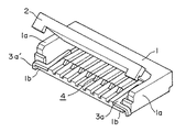
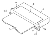
図1は、本発明の一実施例に係るFPC用コネクタの基本構成をアクチュエータ2の開状態で示した外観斜視図である。又、図2は、このFPC用コネクタの基本構成をアクチュエータ2の閉状態によるFPC5の接続状態で示した外観斜視図である。
【0018】
このFPC用コネクタの場合、一軸方向に沿って所定の間隔でこの一軸方向と垂直な他軸方向に延びて配設された第1のコンタクト4を内部に有すると共に、一軸方向に沿って開口形成されて第1のコンタクト4の接触部を露呈させた挿入口を有するハウジング1と、ハウジング1の挿入口近傍に可動に装着されて他軸方向を挿抜方向とするFPC5の挿入口への挿入状態でFPC5を第1のコンタクト4の接触部に対して押圧する押圧可動部材としてのアクチュエータ2とを備える他、挿入口における第1のコンタクト4の両側にFPC5の挿入方向に沿って圧入配設されると共に、少なくとも他軸方向に平板状に延びてFPC5と接触押圧される接触バネ片部,接触バネ片部より一軸方向における挿入口の外方へ向かって平板状に延びた局部から他軸方向に凸状に突出してハウジング1の所定箇所に形成された凹み部に圧入される圧入片部,及び圧入片部より一軸方向及び他軸方向と垂直な別軸方向に延びて図示されないプリント(配線)基板と接続可能な脚端子片部を一体的に形成した左右対称形状の第2のコンタクト3a,3a′を備えている。
【0019】
但し、このFPC用コネクタの場合、ハウジング1は、一主面側に両側壁1aを有して両側壁1a間に段差を成して形成された凹平面部である下面壁1b上に第1のコンタクト4及び第2のコンタクト3a,3a′の接触バネ片部が配設される一主面側開放形状となっており、押圧可動部材としてのアクチュエータ2は、ハウジング1の凹平面部上を覆うように両側壁1aに対して回動可能に取り付けられることでFPC5を挿入する側の一側面の一部を一軸方向に沿って切り欠いて成る切り欠き部が挿入口を形成すると共に、図1に示されるような開状態で挿入口を開放してFPC5を挿入可能とし、且つ図2に示されるような閉状態で開放された挿入口に挿入されたFPC5を第1のコンタクト4の接触部に対して押圧する回動開閉式カバー型となっている。
【0020】
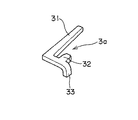
図3は、ここでのFPC用コネクタに用いられる一形態の第2のコンタクト3a,3a′における一方側のコンタクト3aに係る細部構成を示した外観斜視図である。図1,図2において、第1のコンタクト4の右側に配置された第2のコンタクト3aは、例えば図3に示されるように、FPC5の挿抜方向であって、且つ第1のコンタクト4の延在方向である他軸方向に平板状に延びてFPC5と接触押圧される接触バネ片部31と、この接触バネ片部31より第1のコンタクト4の配列方向である一軸方向における挿入口の外方へ向かって同一な平板状に延びた局部から他軸方向に凸状に突出してハウジング1の挿入口両側に形成された凹み部に圧入される圧入片部32と、この圧入片部32より一軸方向及び他軸方向と垂直な別軸方向に延びてプリント基板と接続される脚端子片部33とを一体的に形成した構成となっている。尚、第1のコンタクト4の左側に配置された第2のコンタクト3a′の場合、圧入片部32,脚端子片部33が接触バネ片部31に対して一軸方向で反対向きの外方へ形成される点が相違し、これによって第2のコンタクト3a,3a′は左右対称形として形成されている。
【0021】
このような構成のFPC用コネクタの場合、ハウジング1の内部においてプリント基板との接続を行うための第2のコンタクト3a,3a′をFPC5との接続を行うための第1のコンタクト4の両側に配置するものとし、これらの第2のコンタクト3a,3a′をFPC5の挿入方向に従って圧入装着する構成としているので、全体を小型化及び低背化(薄型化)された構造として容易に製造できる他、ハウジング1の両側壁1aに対して回動可能に取り付けられたアクチュエータ2の開状態でFPC5を挿入口より挿入した後、アクチュエータ2を閉状態とすることでアクチュエータ2がハウジング1に係止されるため、挿入されたFPC5の接続を十分な接触力を発揮するバネ性を有する構造として行うことができる。
【0022】
図4は、本発明の他の実施例に係るFPC用コネクタの基本構成をアクチュエータ2の開状態で示した外観斜視図である。又、図5は、このFPC用コネクタの基本構成をアクチュエータ2の閉状態によるFPC5の接続状態で示した外観斜視図である。
【0023】
このFPC用コネクタの場合、先の一実施例のものと比べ、第1のコンタクト4の左右両側に配置された一形態のコンタクト3a,3a′に代えてそれぞれ他形態のコンタクト3b,3b′を配置構成した点のみが相違している。
【0024】
図6は、ここでのFPC用コネクタに用いられる他形態の第2のコンタクト3b,3b′における一方側のコンタクト3bに係る細部構成を示した外観斜視図である。図4,図5において、第1のコンタクト4の右側に配置された第2のコンタクト3bは、例えば図6に示されるように、第2のコンタクト3aの場合と同様にFPC5の挿抜方向であって、且つ第1のコンタクト4の延在方向である他軸方向に平板状に延びてFPC5と接触押圧される接触バネ片部31と、この接触バネ片部31より第1のコンタクト4の配列方向である一軸方向における挿入口の外方へ向かって同一な平板状に延びた局部から他軸方向に凸状に突出してハウジング1の挿入口両側に形成された凹み部に圧入される圧入片部32とを有する他、圧入片部32より別軸方向に延びた局部から屈曲して一軸方向へ平板状に延びてプリント基板の面と平行に接続される平板状部を有する脚端子片部33′と、この脚端子片部33′の平板状部より別軸方向に延びて先端が屈曲された屈曲部となっていることで屈曲部が閉状態のアクチュエータ2を係合保持してハウジング1に係止させる係合片部34とを有し、これらの接触バネ片部31,圧入片部32,脚端子片部33′,係合片部34を一体的に形成した構成となっている。尚、第1のコンタクト4の左側に配置された第2のコンタクト3b′の場合、圧入片部32,脚端子片部33′,及び係合片部34が接触バネ片部31に対して一軸方向で反対向きの外方へ形成される点が相違し、これによって第2のコンタクト3b,3b′は左右対称形として形成されている。
【0025】
即ち、このような構成のFPC用コネクタの場合も、ハウジング1の内部においてプリント基板との接続を行うための第2のコンタクト3b,3b′をFPC5との接続を行うための第1のコンタクト4の両側に配置するものとし、これらの第2のコンタクト3b,3b′をFPC5の挿入方向に従って圧入装着する構成としているので、全体を小型化及び低背化(薄型化)された構造として容易に製造できる他、ハウジング1の両側壁1aに対して回動可能に取り付けられたアクチュエータ2の開状態でFPC5を挿入口より挿入した後、アクチュエータ2を閉状態とすることで第1のコンタクト4の両側に配置された第2のコンタクト3b,3b′の係合片部34の屈曲部がそれぞれアクチュエータ2を係合保持し、この状態でアクチュエータ2がハウジング1に係止されるため、この場合には挿入されたFPC5の接続を一実施例の場合と比べて一層安定した十分な接触力を発揮するバネ性を有する構造として行うことができる。
【0026】
図7は、本発明の別の実施例に係るFPC用コネクタの基本構成をアクチュエータ6の開状態で示した外観斜視図である。又、図8は、このFPC用コネクタの基本構成をアクチュエータ6の閉状態で示した外観斜視図である。
【0027】
このFPC用コネクタの場合、ハウジング1′は、FPCを挿入する側の一側面の一部を一軸方向に沿って切り欠いて成る切り欠き部が挿入口を形成する箱型側面開口形状となっており、その内部にプリント基板との接続を行うための第2のコンタクト3c,3c′がFPCとの接続を行うための第1のコンタクト4の両側に配置されており、押圧可動部材としてのアクチュエータ6は、ハウジング1′の挿入口内に装着されて挿入口を遮るように他軸方向でスライドすると共に、図7に示されるように他軸方向における一方側の開スライド位置で規定される開状態で挿入口を開放してFPCを挿入可能とし、且つ図8に示されるように他軸方向における他方側の閉スライド位置で規定される閉状態で挿入口に挿入されたFPCを第1のコンタクト4の接触部に対して押圧するスライド開閉式板型となっている。
【0028】
図9は、ここでのFPC用コネクタに用いられる別形態の第2のコンタクト3c,3c′における一方側のコンタクト3cに係る細部構成を示した外観斜視図である。図7,図8において、第1のコンタクト4の右側に配置された第2のコンタクト3cは、例えば図9に示されるように、第2のコンタクト3a,3bの場合と同様にFPC5の挿抜方向であって、且つ第1のコンタクト4の延在方向である他軸方向に平板状に延びてFPC5と接触押圧される接触バネ片部31と、この接触バネ片部31より第1のコンタクト4の配列方向である一軸方向における挿入口の外方へ向かって同一な平板状に延びた局部から他軸方向に凸状に突出してハウジング1の挿入口両側に形成された凹み部に圧入される圧入片部32とを有する他、圧入片部32より別軸方向に延びた局部から屈曲して一軸方向へ平板状に延びてプリント基板の面と平行に接続される平板状部を有する脚端子片部33′と、この脚端子片部33′の平板状部より別軸方向に延びて先端が屈曲された屈曲部となっていることで屈曲部が閉状態のアクチュエータ2を係合保持してハウジング1に係止させる係合片部34′とを有し、これらの接触バネ片部31,圧入片部32,脚端子片部33′,係合片部34′を一体的に形成した構成となっている。尚、第1のコンタクト4の左側に配置された第2のコンタクト3c′の場合、圧入片部32,脚端子片部33′,及び係合片部34′が接触バネ片部31に対して一軸方向で反対向きの外方へ形成される点が相違し、これによって第2のコンタクト3c,3c′は左右対称形として形成されている。
【0029】
即ち、このような構成のFPC用コネクタの場合も、ハウジング1′の内部においてプリント基板との接続を行うための第2のコンタクト3c,3c′をFPCとの接続を行うための第1のコンタクト4の両側に配置するものとし、これらの第2のコンタクト3c,3c′をFPCの挿入方向に従って圧入装着する構成としているので、全体を小型化及び低背化(薄型化)された構造として容易に製造できる他、ハウジング1′の挿入口内に挿入口を遮るように他軸方向でスライド可能に取り付けられたアクチュエータ6の開状態でFPCを挿入口より挿入した後、アクチュエータ6を閉状態とすることで第1のコンタクト4の両側に配置された第2のコンタクト3c,3c′における係合片部34′の屈曲部がそれぞれアクチュエータ6を係合保持し、この状態でアクチュエータ6がハウジング1′に係止されるため、この場合にも挿入されたFPCの接続を一実施例の場合と比べて一層安定した十分な接触力を発揮するバネ性を有する構造として行うことができる。
【0030】
ところで、上述した各実施例のFPC用コネクタでは、第2のコンタクト3a,3a′,3b,3b′,3c,3c′の圧入片部31をハウジング1,1′の挿入口両側に形成された凹み部に圧入するものとしたが、圧入片部31を圧入するための凹み部は他所に設けられても良い。
【0031】
図10は、上述した図1又は図2に示したFPC用コネクタに用いた一形態の第2のコンタクト3a,3a′における一方側のコンタクト3a近傍を変形した場合の細部構成を局部を破断して示した外観斜視図である。即ち、ここではコンタクト3aの圧入片部31を圧入するための凹み部をハウジング1″の挿入口両側でなく、挿入口内の第1のコンタクト4を配設した下面壁1b′に形成するように変形した構成した様子を示している。こうしたハウジング1″側で凹み部の形成箇所を変形した構成は、その他の第2のコンタクト3a′,3b,3b′,3c,3c′の何れの圧入片部31に対しても同様に適用できるので、ここでの変形した構成は上述した各実施例における第2のコンタクト3a,3a′,3b,3b′,3c,3c′の何れを備えた場合にも適用できる。
【0032】
【発明の効果】
以上に説明したように、本発明のFPC用コネクタによれば、ハウジングの内部においてプリント基板との接続を行うための第2のコンタクトをFPCとの接続を行うための第1のコンタクトの両側に配置するものとし、これらの第2のコンタクトをFPCの挿入方向に従って圧入装着する構成としているので、従来のFPC用コネクタ関連の既製品と比べて全体を小型化及び低背化された構造として容易に製造できる他、ハウジングの両側壁に対して回動可能に取り付けられたアクチュエータ又はハウジングの挿入口内にスライド可能に取り付けられたアクチュエータの開状態でFPCを挿入口より挿入した後、アクチュエータを閉状態とすることで第2のコンタクトにアクチュエータが係合保持されて挿入されたFPCの接続を十分な接触力を発揮するバネ性を有する構造として行うことができるようになる。
【0033】
この結果、例えば特開平9−82427号公報に開示されたフラットケーブル用コネクタや特開平8−31526号公報に開示されたラッチ付コネクタの場合にはプリント基板との接続を行うためのコンタクトにおける脚端子片部にスペースを要し、接触バネ片部のバネ性を確保しようとすると全体の小型化が困難になっていたが、本発明のFPC用コネクタの場合、第2のコンタクトにおける脚端子片部と接触バネ片部との延在方向が異なっているため、接触バネ片部の長さ(バネ性)を十分に確保した上で一層小型化を図ることができる。
【0034】
又、本発明のFPC用コネクタの場合、第2のコンタクトにおける圧入片部は、接触バネ片部と隣り合って位置され、ハウジングの挿入口両側や第1のコンタクトを配設した面壁に形成された凹み部に圧入されるため、従来よりも一層低背化を図ることができる。
【0035】
更に、例えば特開平8−31526号公報に開示されたラッチ付コネクタの場合のように、コンタクトが片側方向にのみ配列された構成ではコネクタをプリント基板に安定した姿勢で固定したり、或いはフレキシブル導体との接続強度を向上させるために別途に補強金具を必要としていたが、本発明のFPC用コネクタの場合、第2のコンタクトにおける脚端子片部が接触バネ片部や第1のコンタクトと異なる位置に配置されており、しかもプリント基板の面と平行に接続される平板状部を有するため、補強金具を要すること無く接地面積を十分に確保した上でコネクタを安定した姿勢でプリント基板上に実装接続することができる。
【0036】
加えて、本発明のFPC用コネクタの場合、第2のコンタクトにおける係合片部は、その先端側の屈曲部がFPCを第1のコンタクトに押圧するための押圧可動部材としてのアクチュエータを確実に係合保持してハウジングに係止させるため、FPCの接続を安定した十分な接触力を持って行うことができる。
【図面の簡単な説明】
【図1】本発明の一実施例に係るFPC用コネクタの基本構成をアクチュエータの開状態で示した外観斜視図である。
【図2】図1に示すFPC用コネクタの基本構成をアクチュエータの閉状態によるFPCの接続状態で示した外観斜視図である。
【図3】図1又は図2に示すFPC用コネクタに用いられる一形態の第2のコンタクトにおける一方側のコンタクトに係る細部構成を示した外観斜視図である。
【図4】本発明の他の実施例に係るFPC用コネクタの基本構成をアクチュエータの開状態で示した外観斜視図である。
【図5】図4に示すFPC用コネクタの基本構成をアクチュエータの閉状態によるFPCの接続状態で示した外観斜視図である。
【図6】図4又は図5に示すFPC用コネクタに用いられる他形態の第2のコンタクトにおける一方側のコンタクトに係る細部構成を示した外観斜視図である。
【図7】本発明の別の実施例に係るFPC用コネクタの基本構成をアクチュエータの開状態で示した外観斜視図である。
【図8】図7に示すFPC用コネクタの基本構成をアクチュエータの閉状態で示した外観斜視図である。
【図9】図7又は図8に示すFPC用コネクタに用いられる別形態の第2のコンタクトにおける一方側のコンタクトに係る細部構成を示した外観斜視図である。
【図10】図1又は図2に示すFPC用コネクタに用いられる一形態の第2のコンタクトにおける一方側のコンタクト近傍を変形した場合の細部構成を局部を破断して示した外観斜視図である。
【符号の説明】
1,1′,1″ ハウジング
1a 側面壁
1b,1b′ 下面壁
2,6 アクチュエータ
3a,3a′,3b,3b′,3c,3c′,4 コンタクト
5 FPC
31 接触バネ片部
32 圧入片部
33,33′ 脚端子片部
34,34′ 係合片部[0001]
BACKGROUND OF THE INVENTION
The present invention relates to a small and low-profile FPC connector that has a spring property that exerts a sufficient contact force and stably connects a flexible printed circuit board (hereinafter referred to as an FPC). .
[0002]
[Prior art]
Conventionally, as an example of a well-known technique related to this type of FPC connector, in the case of a flat cable connector disclosed in Japanese Patent Laid-Open No. 9-82427, the main body is configured to be mounted and connectable on a printed (wiring) board. Specifically, a housing that is open upward with the insertion direction of the flat cable as the front-rear direction and a contact portion that extends from the front to the rear of the housing and is in electrical contact with the flat cable are provided. A first contact having a contact piece and a lead terminal piece and having a fixed piece attached from the front side of the housing, and a contact point extending forward from the rear of the housing and electrically contacting the flat cable at the tip A contact piece provided with a portion and a lead terminal piece, and a fixed piece and attached from the rear side of the housing. And a lever portion that is rotatably supported by the elastic support piece of the second contact and presses and fixes the flat cable so that each contact is arranged in the front-rear direction of the housing. The entire connector is downsized.
[0003]
In addition, as another example of the well-known technique related to the FPC connector, in the case of the connector with a latch disclosed in JP-A-8-31526, the main body is configured to be mounted and connectable on a printed (wiring) board. The same, but here a large number of contact pins are mounted in parallel in the front-rear direction of the plastic housing, and the outer side is reinforced by a reinforcing plate attached to a printed circuit board or flexible conductor on one or both sides in the width direction of the housing. And a plastic latch that holds the printed circuit board or the reinforcing plate in a pressure-bonded state by returning them to the original position when they are pushed to a predetermined position, and further receives a contact pressure applied to the latch. Latch for the reinforcing member provided on itself, the latch of the reinforcing member itself, the mounting portion for attaching to the housing, and the housing By forming a support part that is fixed to the printed circuit board to be set, contact failure of the printed circuit board and contact pins due to creep deformation of the latch and damage to the latch when the printed circuit board is inserted and removed can be prevented. The size is reduced.
[0004]
Furthermore, as another example of a well-known technique related to an FPC connector, in the case of a flexible circuit board connector disclosed in Japanese Patent Laid-Open No. 11-54220, the main body is configured to be mounted and connectable on a printed (wiring) board. However, in this case, a pressure member having a tongue piece is rotated on an insulating housing in which a contact portion is formed as a metal plate surface and accommodates a plurality of contacts arranged in a staggered manner so as to be able to contact one side of the flexible circuit board. It is provided so that it can move, and the post on both sides and the elastic engagement piece engage with each other in the open position of the pressure member to prevent the insulation housing from coming off, and the post and elastic engagement piece engage in the closed position. Is released, and the locking projection and the insulating housing are locked, and the tongue piece engages with a part of the contact and is maintained on the insulating housing, so that the flexible circuit board is brought into contact with the contact. It is configured to provide sufficient contact force in which electrical connection presses only.
[0005]
[Problems to be solved by the invention]
In the case of a connector provided for connection to the above-described printed (wiring) board and connection to a flexible flat cable, in order to obtain stable contact as a necessary item in general for ensuring basic functions. The spring length of the contact spring piece part needs to be a certain length in order to realize the contact force, secure the press-fitting piece part for fixing each contact to the housing, and the printed circuit board and the ground To secure a space for mounting metal parts as reinforcing metal fittings, etc., but these necessary items are necessary to realize the miniaturization and low profile (thinning) of the connector as required recently. There is a problem that is hindering.
[0006]
Specifically, in the case of a flat cable connector disclosed in Japanese Patent Laid-Open No. 9-82427, the contacts are arranged in the front-rear direction of the housing to reduce the size of the entire connector. Since the leg terminal piece for electrical connection to the printed circuit board at the contact extends in both sides of the housing, the spring length of the contact spring piece at each contact to obtain a stable contact force as the outer shape of the entire connector is There is a problem that the structure is not shortened so that a stable contact state with the flat cable cannot be obtained. Further, in the case of the connector here, the press-fitting piece for fixing to the housing in each contact is a two-part divided piece, and one piece located on the lower side or the upper side is used. If it is going to embody, there will be a problem that the mold thickness of the housing becomes thin, which makes it impossible to secure sufficient mechanical strength.
[0007]
On the other hand, in the case of a connector with a latch disclosed in Japanese Patent Application Laid-Open No. 8-31526, the entire connector is reduced in size by arranging each contact in the front-rear direction of the housing. In addition to the problem that the leg terminal piece for making electrical connection to the space requires a space, and it is difficult to reduce the size if the spring length of the contact spring piece is secured. Because it is necessary to attach the metal parts for fixing the printed circuit board separately from the contacts in the opposite direction (to fix the connector to the printed circuit board in a stable posture and at the same time improve the connection strength of the flexible conductor) , The space for attaching this metal part to the housing hinders the miniaturization of the entire connector and the reduction in height (thinning). There is a problem going on.
[0008]
On the other hand, in the case of the flexible circuit board connector disclosed in Japanese Patent Application Laid-Open No. 11-54220, a pressure member having a tongue piece is rotatably provided on the insulating housing, and the tongue piece contacts the flexible circuit board in the closed position. It is configured to give a sufficient contact force when it is pressed and electrically connected, but here a space is provided in the height direction for the tongue piece of the pressure member to turn the flexible circuit board so that it can be pressed. Since it is necessary to secure a certain dimension in the height direction, the space for enabling the tongue of the pressure member to be rotated is reduced in size or reduced in height (thinner). There is a problem that it is a hindrance to
[0009]
The present invention has been made to solve such problems, and its technical problem is to provide an FPC connector that can be easily manufactured with a small and low-profile structure having a spring property that exhibits sufficient contact force. It is to provide.
[0010]
[Means for Solving the Problems]
According to the present invention, the first contact disposed in the other axis direction perpendicular to the uniaxial direction is provided at a predetermined interval along the uniaxial direction, and the opening is formed along the uniaxial direction. A housing having an insertion port, and an FPC that is movably mounted in the vicinity of the insertion port of the housing and in which the other axis direction is the insertion / extraction direction, is inserted into the insertion port with respect to the contact portion of the first contact. In an FPC connector comprising a pressing movable member for pressing, the FPC is press-fitted along the insertion direction of the FPC on both sides of the first contact at the insertion port and extends in a flat plate shape at least in the other axis direction. A contact spring piece that is pressed against the outer surface of the contact spring piece, and protrudes in a projecting manner in the other axis direction from a local portion extending outwardly from the contact spring piece portion toward the outside of the insertion port in one axial direction. Formation A press-fit piece that is press-fitted into the recessed portion, and a leg terminal piece that extends from the press-fit piece in the one axial direction and another axis perpendicular to the other axial direction and can be connected to the printed circuit board are integrally formed. Thus, an FPC connector having the second contact is obtained.
[0011]
On the other hand, according to the present invention, in the FPC connector described above, the housing has the first contact on the concave flat surface portion having both side walls on one main surface side and forming a step between the both side walls. And a contact spring piece portion of the second contact is disposed on one main surface side, and the pressing movable member is rotatably attached to both side walls so as to cover the concave flat surface portion of the housing. Thus, a notch formed by cutting a part of one side surface on the side where the FPC is inserted along the uniaxial direction forms an insertion port, and the insertion port is opened in the open state so that the FPC can be inserted. In addition, an FPC connector that is a pivotable open / close cover type actuator that presses the FPC inserted into the opened insertion port in the closed state against the contact portion of the first contact is obtained.
[0012]
On the other hand, according to the present invention, in the FPC connector described above, the housing is a box-shaped side surface in which a notch part formed by cutting out a part of one side surface on the side where the FPC is inserted along the uniaxial direction forms an insertion port. The pressing movable member is mounted in the insertion port of the housing and slides in the other axis direction, and opens the insertion port in an open state defined by an open slide position on one side in the other axis direction. The FPC can be inserted and the slide opening / closing type presses the FPC inserted into the insertion port against the contact portion of the first contact in the closed state defined by the closed slide position on the other side in the other axis direction. An FPC connector that is a plate actuator is obtained.
[0013]
According to the present invention, in any of the FPC connectors described above, the leg terminal piece of the second contact is bent from a local portion extending in the direction of another axis from the press-fit piece and extends in a flat plate shape in the direction of one axis. Thus, an FPC connector having a flat portion connected in parallel with the surface of the printed circuit board is obtained.
[0014]
Furthermore, according to the present invention, in the FPC connector, the second contact engages and holds the pressing movable member in which the bent portion extending in the different axis direction from the flat plate portion of the leg terminal piece portion is in the closed state. Thus, an FPC connector having an engagement piece to be locked to the housing is obtained.
[0015]
In addition, according to the present invention, in any one of the FPC connectors described above, the housing is an FPC connector in which recesses are provided on both sides of the insertion port, or the housing has a recess in the first in the insertion port. An FPC connector formed on the face wall on which the contacts are disposed can be obtained.
[0016]
DETAILED DESCRIPTION OF THE INVENTION
EXAMPLES Examples will be given below and the FPC connector of the present invention will be described in detail with reference to the drawings.
[0017]
FIG. 1 is an external perspective view showing the basic configuration of an FPC connector according to an embodiment of the present invention in an opened state of an
[0018]
In the case of this FPC connector, the
[0019]
However, in the case of this FPC connector, the housing 1 has first side walls 1a on the lower surface wall 1b, which is a concave flat portion having both side walls 1a on one main surface side and forming a step between the both side walls 1a. The contact spring piece portion of the
[0020]
FIG. 3 is an external perspective view showing a detailed configuration of the
[0021]
In the case of the FPC connector having such a configuration, the
[0022]
FIG. 4 is an external perspective view showing the basic configuration of an FPC connector according to another embodiment of the present invention in an opened state of the
[0023]
In the case of this FPC connector, in place of one form of
[0024]
FIG. 6 is an external perspective view showing a detailed configuration of the
[0025]
That is, even in the case of the FPC connector configured as described above, the
[0026]
FIG. 7 is an external perspective view showing the basic configuration of an FPC connector according to another embodiment of the present invention in an opened state of the
[0027]
In the case of this FPC connector, the housing 1 ′ has a box-shaped side opening shape in which a cutout portion formed by cutting out a part of one side surface on the FPC insertion side along the uniaxial direction forms an insertion port. The
[0028]
FIG. 9 is an external perspective view showing a detailed configuration of the
[0029]
That is, even in the case of the FPC connector having such a configuration, the
[0030]
By the way, in the FPC connector of each embodiment described above, the press-fitting
[0031]
FIG. 10 is a partially cut-away view of a detailed configuration when the vicinity of one
[0032]
【The invention's effect】
As described above, according to the FPC connector of the present invention, the second contact for connecting to the printed board inside the housing is provided on both sides of the first contact for connecting to the FPC. Since these second contacts are press-fitted and installed in accordance with the FPC insertion direction, the entire structure is easily reduced in size and height compared to existing FPC connector-related products. In addition, the actuator is closed after the FPC is inserted through the insertion port in the open state of the actuator that is pivotably attached to the both side walls of the housing or the actuator that is slidably mounted in the insertion port of the housing. By doing so, the connection of the FPC inserted with the actuator being engaged and held by the second contact is sufficiently connected. It is possible to perform a structure having a spring property to exert force.
[0033]
As a result, for example, in the case of a flat cable connector disclosed in Japanese Patent Laid-Open No. 9-82427 or a connector with a latch disclosed in Japanese Patent Laid-Open No. 8-31526, the legs in the contacts for connecting to the printed circuit board If the terminal piece portion requires a space and the spring property of the contact spring piece portion is to be secured, it has been difficult to reduce the overall size. However, in the case of the FPC connector of the present invention, the leg terminal piece in the second contact Since the extending direction of the contact spring piece portion is different from that of the contact spring piece portion, it is possible to further reduce the size of the contact spring piece portion while ensuring a sufficient length (spring property).
[0034]
In the FPC connector according to the present invention, the press-fit piece portion of the second contact is located adjacent to the contact spring piece portion, and is formed on the side wall of the housing where the first contact is provided, on both sides of the insertion port of the housing. Since it is press-fitted into the recessed portion, it is possible to further reduce the height as compared with the prior art.
[0035]
Further, for example, in the configuration in which the contacts are arranged only in one side direction as in the case of the connector with a latch disclosed in Japanese Patent Laid-Open No. 8-31526, the connector is fixed to the printed circuit board in a stable posture, or a flexible conductor However, in the case of the FPC connector according to the present invention, the leg terminal piece portion of the second contact is different from the contact spring piece portion and the first contact. In addition, it has a flat part that is connected in parallel with the surface of the printed circuit board, so that it can be mounted on the printed circuit board in a stable posture while securing a sufficient grounding area without requiring a reinforcing bracket. Can be connected.
[0036]
In addition, in the case of the FPC connector of the present invention, the engaging piece portion of the second contact reliably serves as an actuator as a pressing movable member for the bent portion on the tip side to press the FPC against the first contact. Since it is engaged and held and locked to the housing, the FPC can be connected with a stable and sufficient contact force.
[Brief description of the drawings]
FIG. 1 is an external perspective view showing a basic configuration of an FPC connector according to an embodiment of the present invention in an opened state of an actuator.
FIG. 2 is an external perspective view showing the basic configuration of the FPC connector shown in FIG. 1 in an FPC connection state when the actuator is closed.
3 is an external perspective view showing a detailed configuration of a contact on one side of a second contact of one embodiment used in the FPC connector shown in FIG. 1 or FIG. 2. FIG.
FIG. 4 is an external perspective view showing a basic configuration of an FPC connector according to another embodiment of the present invention in an opened state of an actuator.
5 is an external perspective view showing the basic configuration of the FPC connector shown in FIG. 4 in the FPC connection state when the actuator is closed. FIG.
6 is an external perspective view showing a detailed configuration of a contact on one side of a second contact of another embodiment used in the FPC connector shown in FIG. 4 or FIG. 5. FIG.
FIG. 7 is an external perspective view showing a basic configuration of an FPC connector according to another embodiment of the present invention in an opened state of an actuator.
FIG. 8 is an external perspective view showing the basic configuration of the FPC connector shown in FIG. 7 in a closed state of the actuator.
9 is an external perspective view showing a detailed configuration of a contact on one side in a second contact of another form used in the FPC connector shown in FIG. 7 or FIG. 8. FIG.
10 is an external perspective view showing a detailed configuration in which a portion near the contact on one side of the second contact used in the FPC connector shown in FIG. 1 or FIG. .
[Explanation of symbols]
1,1 ', 1 "housing
1a Side wall
1b, 1b 'bottom wall
2,6 Actuator
3a, 3a ', 3b, 3b', 3c, 3c ', 4 contacts
5 FPC
31 Contact spring piece
32 Press-fit piece
33,33 'leg terminal piece
34, 34 'engagement piece
Claims (7)
Priority Applications (1)
| Application Number | Priority Date | Filing Date | Title |
|---|---|---|---|
| JP2000325233A JP3677596B2 (en) | 2000-10-25 | 2000-10-25 | Flexible circuit board connector |
Applications Claiming Priority (1)
| Application Number | Priority Date | Filing Date | Title |
|---|---|---|---|
| JP2000325233A JP3677596B2 (en) | 2000-10-25 | 2000-10-25 | Flexible circuit board connector |
Publications (2)
| Publication Number | Publication Date |
|---|---|
| JP2002134195A JP2002134195A (en) | 2002-05-10 |
| JP3677596B2 true JP3677596B2 (en) | 2005-08-03 |
Family
ID=18802627
Family Applications (1)
| Application Number | Title | Priority Date | Filing Date |
|---|---|---|---|
| JP2000325233A Expired - Fee Related JP3677596B2 (en) | 2000-10-25 | 2000-10-25 | Flexible circuit board connector |
Country Status (1)
| Country | Link |
|---|---|
| JP (1) | JP3677596B2 (en) |
Families Citing this family (5)
| Publication number | Priority date | Publication date | Assignee | Title |
|---|---|---|---|---|
| JP4342904B2 (en) | 2003-10-28 | 2009-10-14 | モレックス インコーポレイテド | FPC connector and FPC connector and FPC connection structure |
| JP4388879B2 (en) | 2004-10-26 | 2009-12-24 | 日本圧着端子製造株式会社 | connector |
| JP4090060B2 (en) | 2004-12-20 | 2008-05-28 | 日本航空電子工業株式会社 | connector |
| KR20070057301A (en) * | 2005-12-01 | 2007-06-07 | 삼성전자주식회사 | Connector for flexible printed circuit, flexible printed circuit inserting the same, and display device having the same |
| JP5974892B2 (en) | 2010-08-31 | 2016-08-23 | コニカミノルタ株式会社 | Biological substance detection method |
-
2000
- 2000-10-25 JP JP2000325233A patent/JP3677596B2/en not_active Expired - Fee Related
Also Published As
| Publication number | Publication date |
|---|---|
| JP2002134195A (en) | 2002-05-10 |
Similar Documents
| Publication | Publication Date | Title |
|---|---|---|
| US7063559B2 (en) | Flexible printed circuit electrical connector | |
| JP5093340B2 (en) | Connector device | |
| JP2002252061A (en) | Electric connector | |
| JP2001283958A (en) | Locking structure for board connector | |
| US6524114B2 (en) | Board connecting terminal and connector using the terminal | |
| US7396241B2 (en) | Method of producing lever of lever-fitting type connector | |
| JP5741828B2 (en) | Connector device | |
| US20100130045A1 (en) | Connector for Flexible Circuit | |
| KR20000077115A (en) | Electrical connector for flexible printed board | |
| JP3732157B2 (en) | Flexible board connector | |
| US20030157829A1 (en) | Flat circuit connector | |
| JP2002252067A (en) | Electric connector | |
| JPH0677178U (en) | Electrical connector for circuit board with latch | |
| JPH1126073A (en) | Lever-fitting type connector | |
| JP3677596B2 (en) | Flexible circuit board connector | |
| JP2010027520A (en) | Connector device | |
| JPH07335342A (en) | Connector for flexible conductor | |
| JP4109978B2 (en) | FPC connector and mobile phone using the same | |
| JP2000058173A (en) | Fpc connecting connector | |
| JP2001319712A (en) | Connector and connecting structure between connector and circuit board | |
| JP2002093526A (en) | Flexible conductor and its joint connector | |
| JPH11135179A (en) | Connector socket | |
| US10122104B2 (en) | Connector for a flexible printed circuit | |
| JP3473897B2 (en) | Electrical junction box | |
| JP4275453B2 (en) | Electrical connector |
Legal Events
| Date | Code | Title | Description |
|---|---|---|---|
| A977 | Report on retrieval |
Free format text: JAPANESE INTERMEDIATE CODE: A971007 Effective date: 20050329 |
|
| TRDD | Decision of grant or rejection written | ||
| A01 | Written decision to grant a patent or to grant a registration (utility model) |
Free format text: JAPANESE INTERMEDIATE CODE: A01 Effective date: 20050413 |
|
| A61 | First payment of annual fees (during grant procedure) |
Free format text: JAPANESE INTERMEDIATE CODE: A61 Effective date: 20050421 |
|
| R150 | Certificate of patent or registration of utility model |
Free format text: JAPANESE INTERMEDIATE CODE: R150 |
|
| FPAY | Renewal fee payment (event date is renewal date of database) |
Free format text: PAYMENT UNTIL: 20080520 Year of fee payment: 3 |
|
| FPAY | Renewal fee payment (event date is renewal date of database) |
Free format text: PAYMENT UNTIL: 20090520 Year of fee payment: 4 |
|
| FPAY | Renewal fee payment (event date is renewal date of database) |
Free format text: PAYMENT UNTIL: 20100520 Year of fee payment: 5 |
|
| FPAY | Renewal fee payment (event date is renewal date of database) |
Free format text: PAYMENT UNTIL: 20110520 Year of fee payment: 6 |
|
| FPAY | Renewal fee payment (event date is renewal date of database) |
Free format text: PAYMENT UNTIL: 20120520 Year of fee payment: 7 |
|
| FPAY | Renewal fee payment (event date is renewal date of database) |
Free format text: PAYMENT UNTIL: 20120520 Year of fee payment: 7 |
|
| FPAY | Renewal fee payment (event date is renewal date of database) |
Free format text: PAYMENT UNTIL: 20120520 Year of fee payment: 7 |
|
| FPAY | Renewal fee payment (event date is renewal date of database) |
Free format text: PAYMENT UNTIL: 20130520 Year of fee payment: 8 |
|
| FPAY | Renewal fee payment (event date is renewal date of database) |
Free format text: PAYMENT UNTIL: 20130520 Year of fee payment: 8 |
|
| FPAY | Renewal fee payment (event date is renewal date of database) |
Free format text: PAYMENT UNTIL: 20130520 Year of fee payment: 8 |
|
| FPAY | Renewal fee payment (event date is renewal date of database) |
Free format text: PAYMENT UNTIL: 20140520 Year of fee payment: 9 |
|
| R250 | Receipt of annual fees |
Free format text: JAPANESE INTERMEDIATE CODE: R250 |
|
| R250 | Receipt of annual fees |
Free format text: JAPANESE INTERMEDIATE CODE: R250 |
|
| LAPS | Cancellation because of no payment of annual fees |