JP3677585B2 - Open end felt with seam - Google Patents
Open end felt with seam Download PDFInfo
- Publication number
- JP3677585B2 JP3677585B2 JP2001336219A JP2001336219A JP3677585B2 JP 3677585 B2 JP3677585 B2 JP 3677585B2 JP 2001336219 A JP2001336219 A JP 2001336219A JP 2001336219 A JP2001336219 A JP 2001336219A JP 3677585 B2 JP3677585 B2 JP 3677585B2
- Authority
- JP
- Japan
- Prior art keywords
- yarn
- loop
- cmd
- base fabric
- layer
- Prior art date
- Legal status (The legal status is an assumption and is not a legal conclusion. Google has not performed a legal analysis and makes no representation as to the accuracy of the status listed.)
- Expired - Fee Related
Links
Images

Landscapes
- Woven Fabrics (AREA)
- Paper (AREA)
Description
【0001】
【発明の属する技術分野】
本発明は、製紙機用プレスフエルト,ドライフエルト,ドライキャンバス,パルプマシン用フエルトに関し、その基布のシーム部の組織に特徴を有する。
【0002】
【従来の技術】
抄紙機或いはパルプマシン(以後マシンという)に使用されるフエルトにはエンドレスに作られたものがあり、この種フエルトはマシンに装架する際にはマシンの複数のロールを片持式にしてマシンの片側から掛け入れなければならず、危険を伴い、またその作業に時間を要していた。そのため、マシンへの掛け入れが容易で安全なシーム付オープンエンドフエルトが望まれるようになった。
【0003】
シーム付オープンエンドフエルトは、図1Aに示す如く、製織時の経糸即ち織機上の経糸Gの間に緯糸Ca,Cbを打ち込み基布Dを構成し、環状に織り上げた二重或るいは多重織物を、製織後耳糸Sを取り去り、一度、織機上の緯糸Ca,Cb方向に長さの有る有端帯状にし、マシンに引き入れてから基布の両端を継ぎ合わせ再度環状にしたもので、シーム付オープンエンドフエルトとしてマシンに装架されるときは、前記織機上の経糸Gはマシン上の緯方向CROSS MACHINE DIRECTION糸(以下CMD糸と云う)となり、織機上の緯糸はマシン上の経方向MACHINE DIRECTION糸(以下MD糸と云う)となる。マシンへの装架は次のようにして行われる。即ち、操業中のマシンを停止し装架されているフエルトを切断して新フエルトと旧フエルトとを仮止めした後、若しくは旧フエルトの代りに予めフエルトの走行経過に沿ってロープ等を通して、前記ロープ等と新フエルトとを仮止めした後、旧フエルト若しくはロープ等をマシンより引き出すことで新フエルトをマシンに引き入れ、旧フエルト若しくはロープ等を取り外し、新フエルトの両端にあらかじめ設けられているループを交互に突き合わせ、該ループ内にピンシームを挿通することによりエンドレスとしている。
【0004】
然し製紙機用プレスフエルトは、幅が広く、基布に使用する糸は、一般的に柔軟性を有し、細く、マシン縦方向を向くMD糸の糸密度も高く、またループ径も小さいために、シーム部における上記突き合わせ作業は困難となる。ナイロンなどのMD糸の場合吸水性を有し、次第にMD糸の柔軟性に変化つまりループの剛性が低下し時間の経過と共に挿通に困難さを増すことも生じていた。
【0005】
更に、基布の組織によってはシーム部のループの根元の上糸Eaと下糸Faとを含む仮想面(Ea−Fa面)が基布面に対して垂直ではなく、斜に捩れる場合にループの噛み合わせが困難となり、一層ピンシームを挿通しにくくなる。さらに、その捩れる角度及び向きが不規則な場合、挿通は一層困難となる。その上、CMD糸が吸水性を有しているナイロン等の場合、次第にCMD糸の屈曲の度合いが変化し、ループが位置する仮想面の基布面に体する角度も、ループの二重性(CMD方向に対しての垂直性)が崩れる角度に変化し、ループの噛み合わせをより一層困難とさせる。
【0006】
更に、シーム部でのピンシームの挿通が容易であっても、シーム部とそれ以外の基布部分との間に抄紙性能上の差が生じては、シーム部での紙切れ、紙繊維の乱れ等による紙の表面性不良等につながる恐れがあった。
【0007】
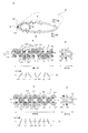
上記ループが基布Dに対して捩れを生ずる原因は次のように考えられる。一例として二重織で、かつ、製織時にループを作成する場合を取り上げる。シームフェルトは図1に示す如く表側地Aと裏側地Bとよりなる二重織に製織し、表側地Aと裏側地Bとが織機上の緯糸Ca,Cb(MD糸)で作られたループLa,Lb中に位置する耳糸Sにより筒状に連結されている基布Dを含む構成を有している。上記筒状の基布Dの表側地Aは、織地端で前記耳糸Sに巻回しループLaを構成している織機上の緯糸Ca(MD糸)の上糸層Eaと下糸層Faとが織機上の経糸Ga(CMD糸)に打ち込まれて作られており、裏側地Bは、織地端で前記耳糸Sに巻回しループLbを構成している織機上の緯糸Cb(MD糸)の上糸層Ebと下糸層Fbとが織機上の経糸Gb(CMD糸)に打込まれて作られている。ここで層の語句を使用したが、その理由は、各糸層Ea,Fa,Eb,Fbを構成する織機上の緯糸(MD糸)は複数接近した状態で並列して打ち込まれており、それら複数の糸がループLa,Lbの基部ではあたかも一つの層をなしているようにも見受けられるからである。
基布Dの表側地Aの織機上の経糸Ga(裏側地Bの織機上の経糸をGbとする)(共にCMD糸)に沿った端面(織機上の緯糸Ca(MD糸)によるループLaに添った端面)を模式的に示したたのが図1Bである。
【0008】
図1Bは表側地Aの断面を示しているが、図1Bにおいて、ループLa列を構成するMD糸Caの間をCMD糸Gaは通っている。図1Aに示すようにMD糸Caは基布Dの端部で耳糸Sを巻回しループLaを作り、図1Bには図示しないMD糸Cbは、図1Aに示す如く耳糸Sに巻回してループLbを作る。MD糸Ca,Cbにおいて、耳糸Sの上に位置する糸列を上糸層Ea,Ebとし、耳糸Sを巻回して耳糸Sの下位の糸を下糸層Fa,Fbとしている。
【0009】
図1Bの点線で示す基布Dの1循環内において、織機上の緯糸即ちMD糸Caが織機上の経糸即ちCMD糸Gaによりどのような力を受けるか次に説明する。通常ループ際の組織は、図1Bに示すようにCMD糸GaがループLaの根元の上糸層Eaと下糸層Faとに交叉している。つまり、CMD糸Gaが、ループLaの根元のMD糸Ea及びFaの自由度を制限している。しかし、帯状時の基布Dの一端に現れるループLa列と該基布Dの他端に現われるループLb列を突き合わせる際、ループLa本体の傾き角度を制限するものではない。このことは、ループLa本体の傾きの角度は、ループLaの根元の影響を大きく受けることを意味している。そして、その影響の大きさは、ループLa本体に近ければ近い程大きい、すなわちCMD糸Ga2よりもCMD糸Ga1の方がループLaの傾き角度に大きな影響を及ぼしていることは明らかである。
【0010】
CMD糸Ga1は、下糸層Faの糸Fa4と同Fa1の間、下糸層の糸Fa1と同Fa2の間、下糸層の糸Fa2と上糸層の糸Ea2の間、上糸層の糸Ea2と同Ea3の間、上糸層の糸Ea3と同Ea4の間、上糸層の糸Ea4と下糸層の糸Fa4の間、下糸層の糸Fa4と同Fa1の間を通り、これを繰り返している。そしてこの間下糸層の糸Fa1と同Fa2の間から上糸層Ea2と同Ea3の間及び上糸層の糸Ea3と同Ea4の間から下糸層の糸Fa4と同Fa1の間を屈曲はしているが直角ではなく(90°以上)多かれ少なかれ斜に通っている。
【0011】
この為、ループLa2にあっては、上糸層の糸Ea2が同Ea1側にずれ易く、下糸層の糸Fa2が同Fa3側にずれ易く、結果的にループLa2が図1B″に示す如く斜に捩れることになる。ループLa4についても同様の理由から捩れが生ずる。捩れの方向を図1Bに矢印で示す。然し、下糸層Faの糸Fa1及び上糸層Eaの糸Ea3はその両側にCMD糸Ga1が通っており、該糸により両側を押えられているのでずれにくい。また、上糸層の糸Ea1及び下糸層の糸Fa3はCMD糸Ga1との交差がないが、CMD糸Ga2と交差しているためCMD糸Ga2の影響を受ける。
図1C,C′,C″に示す例ではCMD糸Ga1とGa2とが交互に1ピッチずらして同じ組織を繰り返し基布Dを構成している。
そのため、CMD糸Ga1がMD糸Fa1,Ea3をCMD糸Ga2がMD糸Ea1,Fa3をその両側から支える状態となるが、そのときCMD糸Ga1はMD糸Fa2,Ea2,Ea4,Fa4を図1Cに示す矢印方向に押しやる作用をする。
また、CMD糸Ga2は、MD糸,Ea4,Ea2,Fa2,Fa4を図1Cに示す矢印と逆の方向に押しやる作用をするが、Ga1よりは小さい。その結果ループLa2,La4は図1C″に示すように傾倒することになる。
【0012】
【発明が解決しようとする課題】
本発明は、上記の点に鑑みて、フエルトの基布面に対して垂直となり、かつ、フエルト走行方向とも一致する仮想平面上にシーム部のループを位置させることによりループ方向を揃えシーム部への耳糸の挿入を容易とすると共に、シームした際に該シーム部を他の部分の基布と同等の表面状態とする事の出来るフエルトを得ることを目的とする。
【0013】
二重織又は多重織シーム付フェルトの、表側地及び裏側地のシーム部を形成する上糸層及び下糸層よりなる基布のMD糸で形成されたループが、該ループに隣接する一側方のループ側に捩れるのを防止する為、基布の最もシーム部に近いCMD糸のループ側に、基布CMD糸とは別な上糸層のMD糸にのみ交絡するループ固定CMD糸と、基布CMD糸とは別な下糸層のMD糸にのみ交絡するループ固定CMD糸とをループ基部に織り込み、ループを形成する上糸層又は下糸層の1つのMD糸が、基布端部を作るCMD糸に片側でのみ接触しているとき、前記MD糸が前記接触側面と反対側の側面でCMD糸と接するようループ固定CMD糸を配し、該糸によりループの捩れを防止した。
また、ループ固定CMD糸は、その太さを基布を構成するCMD糸と同等若しくはそれより細くすることで、より安定した走行を得ることが出来る。また、ループ固定CMD糸の太さを基布を構成するCMD糸より細くすることでシーム部へのウエブの付着量を多くしている。
【0014】
【発明の実施の形態】
本発明の実施の形態を図面と共に以下説明する。
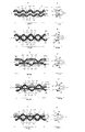
図2A乃至Eに本発明の第1乃至第5実施形態のシーム部端縁部分を模式図で示す。図2A´乃至E´は、図2A乃至Eの一点鎖線における断面図である。図2A乃至Eに示す第1乃至第5の実施形態においてその基布Dの組織は図1に示す従来製品と同じで、図示の基布Dは経緯糸により二重織又は多重織の筒状に織り上げ、耳糸を引き抜き一旦帯状としてマシンに引き入れてから織地の両端縁に作ったループを付き合わせ該ループ内に耳糸を通すことで基布は環状とされる。製織時緯糸として経糸間に打ち込まれた糸は、環状の製品となったときは製紙機の経方向を向くことになる。そこで、以後の説明では製織時経糸であった製品上の緯方向糸をCMD(CROSS MACHINE DIRECTION)糸と呼び、製織時緯糸であった製品上の経方向糸をMD(MACHINE DIRECTION)糸と呼んで説明する。
【0015】
以下5つの実施形態について説明するが、夫々基布組織は同一とし(異なる基布構造としても良い事は勿論である)、ループを構成するシーム部においてループの直立性を高めるための手段が各実施例において異なっている。第1の実施形態として組織図を図2A,A´に示す。この組織では、基布Dの最もシーム部に近いCMD糸10のループLa側に、基布CMD糸とは別な上糸層EaのMD糸Ea1,Ea2・・・・にのみ交絡するループ固定CMD糸20aと、基布CMD糸とは別な下糸層FaのMD糸Fa1,Fa2・・・・にのみ交絡するループ固定CMD糸20bとを配している。
【0016】
ループ固定CMD糸20aは上糸層EaのMD糸Ea1,Ea2間を上から下に同Ea2,Ea3間を下から上に、同Ea3,Ea4の間を上から下にそれぞれ通過し、MD糸Ea1,Ea2,Ea3,Ea4の間に必ずループ固定CMD糸20aが存在するようにしている。下糸層Faにおいても上記上糸層Eaと同様に、下糸層の糸Fa1,Fa2間を上から下に、Fa2,Fa3間を下から上に、Fa3,Fa4間を上から下にそれぞれ通過させ、各糸層Ea,Fa間には必ずループ固定CMD糸20a,20bを位置させることにより各MD糸Ea1,Ea2……Fa1,Fa2……によって作られるループL1,L2……の基部を固定することによって前記ループが常に基布面に対して垂直でマシン縦方向と一致する仮想平面上に位置するように固定されることになる。ループ固定CMD糸20aは上糸層Eaの糸Ea1,Ea2……と、ループ固定CMD糸20bは下糸層Faの糸Fa1,Fa2……とのみそれぞれ交差し、ループ固定CMD糸20aが下糸層Faの糸と交差しループ固定CMD糸20bが上糸層Eaの糸と交差することはない。
【0017】
図2のB,B´に示す実施形態様は、図2のA,A´に示す実施態様の下糸層Faの糸Fa1,Fa2……にからむループ固定CMD糸20bのピッチを1ピッチ横にずらしたものである。即ち、上糸層Eaの糸Ea1にはその上部をループ固定CMD糸20aが巻回しているが下糸層の糸Fa1にはその下部をループ固定CMD糸20bが巻回している。最もシーム部に近いCMD糸10(Ga1)の次にループLa1から遠いCMD糸Ga2の影響を受けるが、ループ固定CMD糸20a及び20bがそれぞれMD糸Ea1及びFa3の両脇を通ることでMD糸Ea1とMD糸Fa3によるループLa1,La3が常に基布D面に対して垂直でマシン縦方向と一致する仮想平面上に位置するように固定されることになる。
【0018】
図2のC,C´に示す実施態様は、上記2例に記したものとは別の形態を示している。即ち、MD糸Ea2はCMD糸10によってEa1側にずれるが、ループ固定CMD糸20aをMD糸Ea2のEa1側にのみ接する位置に配して、このずれを抑制することを可能としている。また、上糸層EaのMD糸Ea1と下糸層FaのMD糸Fa3は、CMD糸10(Ga1)の影響は受けずCMD糸10(Ga1)の次にループLa1から遠いCMD糸Ga2の影響を受けるが、ループ固定CMD糸20a及び20bがそれぞれMD糸Ea1及びFa3の両脇を通ることでMD糸Ea1とMD糸Fa3によるループLa1,La3が常に基布D面に対して垂直でマシン縦方向と一致する仮想平面上に位置するように固定されることになる。
【0019】
図2のD,D´に示す実施態様は、上糸層EaのMD糸Ea2のズレの抑制の仕方を、図2のC,C´に示すループ固定CMD糸20aが、MD糸Ea1の下方からEa2の上方に位置させたものとは逆に、ループ固定CMD糸20aがMD糸Ea1の上方からMD糸Ea2の下方に位置させている。またCMD糸10によってMD糸Ea3が下糸層FaのMD糸Fa3側に近づくことも抑制している。この実施例では、下糸層Faのループ固定CMD糸20bは図2のC,C´に示す実施態様と同じものとした。
【0020】
図2のE,E´に示す実施態様は、図2のB,B´に示す実施態様の下糸層FaのMD糸Fa1〜Fa4を固定する手段と、図2のD,D´に示す実施態様の上糸層EaのMD糸Ea2及びEa4のズレを抑制する手段とを組み合わせてなるものであり、この他にも多様な組み合わせが可能である。
【0021】
上記の各実施態様において基布Dの最もループLに近いCMD糸10の太さに比してループ固定CMD糸20a,20bは同等の太さか細い糸を使用している。一般にフエルトは湿紙に接触する面(ペーパーサイド)よりも、その裏面(バックサイド)のウエブの量は少なく、中にはほとんど無い場合もある。フエルトのバックサイド側が磨耗しやすい場合には、一例として図2Bに示す組織とし、基布Dのループに近いCMD糸10(Ga1とGa2)よりも細いループ固定用CMD糸20a,20bを使用すればループ固定用CMD糸20a,20bは、CMD糸10(Ga1,Ga2)よりもその面が基布Dの面より内側に位置することが出来、ループ固定用CMD糸20a,20bの糸切れによる糸の飛び出しを予防する効果を有する。このように、上糸層Eaと下糸層Faに通したCMD糸の太さは同じではなくとも良い。但し抄紙機の流れ方向で他の部分よりも極端に厚くならないように配慮する必要がある。上糸層Eaと下糸層Faに通したCMD糸は複数本でも良く同じ本数にする必要はない。このときループLに近付くにつれ、通したCMD糸の太さを細くするとスムーズな走行が得られる。CMD糸として通す糸の種類は特に問わない。
【0022】
上記基布Dは、その面上にウエブを置きニードルパンチすることで基布Dとウエブとを一体化してフエルトとして完成される。このときシーム部表面にも当然ウエブが置かれニードルパンチされるがシーム部のループ固定CMD糸20a,20bを基布Dを構成する糸に比して十分に細い糸とすると、該部のウエブの量を多くしたのと同等の結果を得、かつ、糸へのウエブのからみ突きが良好となり、該部でのウエブの剥落も少なくなる。
【0023】
【発明の効果】
二重織又は多重織シーム付フェルトの、表側地及び裏側地のシーム部を形成する上糸層及び下糸層よりなる基布のMD糸で形成されたループが、該ループに隣接する一側方のループ側に捩れるのを防止する為、基布の最もシーム部に近いCMD糸のループ側に、基布CMD糸とは別な上糸層のMD糸にのみ交絡するループ固定CMD糸と、基布CMD糸とは別な下糸層のMD糸にのみ交絡するループ固定CMD糸とをループ基部に織り込み、ループを形成する上糸層又は下糸層の1つのMD糸が、基布端部を作るCMD糸に片側でのみ接触しているとき、前記MD糸が前記接触側面と反対側の側面でCMD糸と接するようループ固定CMD糸を配したために、ループの基部がその一側においてのみ基布Dの最もループに近いCMD糸と接しているとき、ループの他側はループ固定CMD糸と接することにより、シーム部のMD糸によるループLaがその基部をループ固定CMD糸によって固定され、ループLaは基布面に対し垂直となり、またその方向も基布経方向に揃うことになり、シーム部ループLaにシーム糸Sを通す作用が容易となった。
【0024】
基布を構成する糸に比してループ固定CMD糸の太さを細くすれば該部に集まるウエブの量は多くなり、かつ、細糸へのウエブのからみ付きも良好となるためシーム部でのウエブの剥落も少なくなる。
【図面の簡単な説明】
【図1】Aは、基布製織時の打込み糸方向を説明する模式図。
Bは、従来の基布におけるシーム部分のループ列及びそれに沿ったCMD糸(製品緯糸)を示す模式図。B´は前記Bのシーム部の鎖線における縦断面図。B″は隣接するループを含む仮想面の傾きを示す模式図。
Cは、従来の基布におけるシーム部分のループ列及びそれに沿ったCMD糸(製品緯糸)を示す第2例の模式図。C´は前記Bのシーム部の鎖線における縦断面図。C″は隣接するループを含む仮想面の傾きを示す模式図。
【図2】Aは第1の実施形態のシーム部分のループ列及びそれに沿ったCMD糸(製品緯糸)を示す模式図。A´は図2Aの鎖線における断面図。
Bは第2の実施形態のシーム部分のループ列及びそれに沿ったCMD糸(製品緯糸)を示す模式図。B´は図2Bの鎖線における断面図。
Cは第3の実施形態のシーム部分のループ列及びそれに沿ったCMD糸(製品緯糸)を示す模式図。C´は図2Cの鎖線における断面図。
Dは第4の実施形態のシーム部分のループ列及びそれに沿ったCMD糸(製品緯糸)を示す模式図。D´は図2Dの鎖線における断面図。
Eは第5の実施形態のシーム部分のループ列及びそれに沿ったCMD糸(製品緯糸)を示す模式図。E´は図2Eの鎖線における断面図。
【図3】本発明の更に他の実施形態を示し、Aはシーム部分のループ列及びそれに沿ったCMD糸(製品緯糸)を示す模式図。A´は図3Aの鎖線における断面図。
【符号の説明】
A 表側地
B 裏側地
Ca,Cb 織機上の緯糸(MD糸)
D 基布
Ea,Eb 上糸層
Fa,Fb 下糸層
G 織機上の経糸(CMD糸)
La,Lb ループ
S 耳糸
H シーム部
20a,20b ループ固定CMD糸[0001]
BACKGROUND OF THE INVENTION
The present invention relates to a press felt for a paper machine, a dry life felt, a dry canvas, and a felt for a pulp machine, and has a feature in the structure of a seam portion of the base fabric.
[0002]
[Prior art]
Some felts used in paper machines or pulp machines (hereinafter referred to as “machines”) are made endlessly. When this type of felt is mounted on a machine, the machine roll is cantilevered. It had to be hung from one side, and it was dangerous and time consuming. Therefore, an open-end felt with a seam that is easy to put into the machine and safe is desired.
[0003]
As shown in FIG. 1A, the open end felt with seam is a double or multiple woven fabric in which wefts Ca and Cb are driven between warp yarns during weaving, that is, warp yarns on a loom, to form a base fabric D and woven in an annular shape. After weaving, the ear yarn S is removed, and once it is made into a strip with a length in the direction of the weft Ca, Cb on the loom, it is drawn into the machine, and then both ends of the base fabric are joined together to form an annular shape. When mounted on a machine as an open-end felt, the warp G on the loom becomes the weft CROSS MACHINE DIRECTION yarn (hereinafter referred to as CMD yarn) on the machine, and the weft on the loom becomes the warp MACHINE on the machine. DIRECTION yarn (hereinafter referred to as MD yarn). Mounting on the machine is performed as follows. That is, after stopping the machine in operation and cutting the mounted felt to temporarily fix the new felt and the old felt, or instead of the old felt in advance along the travel of the felt through the rope etc. After temporarily fixing the rope etc. and the new felt, pull the old felt or rope etc. out of the machine, pull the new felt into the machine, remove the old felt or rope etc., and loops provided in advance at both ends of the new felt It is made endless by alternately butting and inserting a pin seam into the loop.
[0004]
However, press felts for paper machines are wide, and the yarns used for the base fabric are generally flexible, thin, and the MD yarns oriented in the machine longitudinal direction have a high yarn density and a small loop diameter. In addition, the above-described butting work at the seam portion becomes difficult. In the case of MD yarn such as nylon, it has water absorption, and gradually changes in flexibility of MD yarn, that is, the rigidity of the loop is lowered, and the difficulty of insertion increases with time.
[0005]
Further, depending on the structure of the base fabric, when the virtual surface (Ea-Fa surface) including the upper thread Ea and the lower thread Fa at the root of the loop of the seam portion is not perpendicular to the base fabric surface but twists obliquely. It becomes difficult to mesh the loops, and it becomes more difficult to insert the pin seam. Further, if the twisting angle and direction are irregular, the insertion becomes more difficult. In addition, when the CMD yarn is made of nylon or the like having water absorption, the degree of bending of the CMD yarn gradually changes, and the angle formed on the base fabric surface of the virtual surface where the loop is located is also determined by the loop duality (CMD The angle (verticality with respect to the direction) is changed to an angle at which the loop is broken, and the engagement of the loops is made more difficult.
[0006]
Furthermore, even if it is easy to insert a pin seam at the seam part, if there is a difference in papermaking performance between the seam part and the other base fabric part, paper breakage at the seam part, paper fiber disturbance, etc. This could lead to poor surface properties of the paper.
[0007]
The reason why the loop is twisted with respect to the base fabric D is considered as follows. As an example, let us take up a case of double weaving and creating a loop during weaving. As shown in FIG. 1, the seam felt is woven into a double weave consisting of a front side fabric A and a back fabric B, and the front fabric A and the back fabric B are made of weft Ca, Cb (MD yarn) on the loom. It has a configuration including a base fabric D connected in a cylindrical shape by ear threads S located in La and Lb. The front side fabric A of the cylindrical base fabric D includes an upper yarn layer Ea and a lower yarn layer Fa on the weft Ca (MD yarn) on the loom that is wound around the ear yarn S at the end of the fabric and constitutes the loop La. Are weaved into warp yarn Ga (CMD yarn) on the loom, and the back side fabric B is wound around the ear yarn S at the end of the fabric to form the loop Lb. The weft Cb (MD yarn) on the loom The upper yarn layer Eb and the lower yarn layer Fb are driven into warp Gb (CMD yarn) on the loom. Here, the term “layer” is used because the weft yarns (MD yarns) on the looms constituting each yarn layer Ea, Fa, Eb, Fb are driven in parallel in a plurality of close states. This is because a plurality of yarns appear to form a single layer at the bases of the loops La and Lb.
On the loop La by the end surface (weft yarn Ca (MD yarn) on the loom) along the warp Ga on the loom of the front side fabric A of the base fabric D (Gb is the warp yarn on the loom of the back side fabric B) (both are CMD yarns) FIG. 1B schematically shows the attached end face.
[0008]
FIG. 1B shows a cross section of the front side ground A. In FIG. 1B, the CMD yarn Ga passes between the MD yarns Ca constituting the loop La row. As shown in FIG. 1A, the MD yarn Ca winds the ear yarn S around the end of the base fabric D to form a loop La, and the MD yarn Cb (not shown in FIG. 1B) winds around the ear yarn S as shown in FIG. 1A. Loop Lb. In the MD yarns Ca and Cb, yarn rows positioned on the ear yarn S are upper yarn layers Ea and Eb, and the ear yarn S is wound and lower yarns of the ear yarn S are lower yarn layers Fa and Fb.
[0009]
Next, how the weft on the loom, that is, the MD yarn Ca, is received by the warp on the loom, that is, the CMD yarn Ga in one circulation of the base fabric D shown by the dotted line in FIG. 1B will be described. In the normal loop structure, as shown in FIG. 1B, the CMD yarn Ga crosses the upper yarn layer Ea and the lower yarn layer Fa at the root of the loop La. That is, the CMD yarn Ga restricts the degree of freedom of the MD yarns Ea and Fa at the base of the loop La. However, when the loop La row appearing at one end of the base fabric D and the loop Lb row appearing at the other end of the base fabric D are matched with each other, the inclination angle of the loop La body is not limited. This means that the inclination angle of the loop La body is greatly influenced by the root of the loop La. It is clear that the magnitude of the influence is larger as the distance from the loop La body is closer, that is, the CMD yarn Ga1 has a greater influence on the inclination angle of the loop La than the CMD yarn Ga2.
[0010]
The CMD yarn Ga1 is between the yarn Fa4 and Fa1 of the lower yarn layer Fa, between the yarn Fa1 and Fa2 of the lower yarn layer, between the yarn Fa2 of the lower yarn layer and the yarn Ea2 of the upper yarn layer, Passing between the yarns Ea2 and Ea3, between the yarns Ea3 and Ea4 of the upper yarn layer, between the yarn Ea4 of the upper yarn layer and the yarn Fa4 of the lower yarn layer, between the yarn Fa4 and Fa1 of the lower yarn layer, This is repeated. During this time, bending is performed between the threads Fa1 and Fa2 of the lower thread layer and between the upper thread layers Ea2 and Ea3 and between the threads Ea3 and Ea4 of the upper thread layer and between the threads Fa4 and Fa1 of the lower thread layer. However, it is not a right angle (90 ° or more) but passes more or less obliquely.
[0011]
For this reason, in the loop La2, the yarn Ea2 of the upper yarn layer is easily shifted to the Ea1 side, and the yarn Fa2 of the lower yarn layer is easily shifted to the Fa3 side. As a result, the loop La2 is as shown in FIG. For the same reason, the loop La4 is twisted for the same reason, and the direction of twist is indicated by an arrow in Fig. 1B, but the thread Fa1 of the lower thread layer Fa and the thread Ea3 of the upper thread layer Ea are The CMD yarn Ga1 passes through both sides, and the sides are pressed by the yarn so that they are not easily displaced.Also, the yarn Ea1 of the upper yarn layer and the yarn Fa3 of the lower yarn layer do not intersect with the CMD yarn Ga1, but CMD Since it intersects the yarn Ga2, it is affected by the CMD yarn Ga2.
In the example shown in FIGS. 1C, C ′, and C ″, the CMD yarns Ga1 and Ga2 are alternately shifted by one pitch, and the same structure is repeatedly formed in the base fabric D.
Therefore, the CMD yarn Ga1 is in a state of supporting the MD yarns Fa1, Ea3 and the CMD yarn Ga2 is supporting the MD yarns Ea1, Fa3 from both sides. It acts to push in the direction of the arrow shown.
The CMD yarn Ga2 acts to push the MD yarn, Ea4, Ea2, Fa2, Fa4 in the direction opposite to the arrow shown in FIG. 1C, but is smaller than Ga1. As a result, the loops La2 and La4 are tilted as shown in FIG. 1C ″.
[0012]
[Problems to be solved by the invention]
In view of the above points, the present invention aligns the loop direction to the seam portion by positioning the loop of the seam portion on a virtual plane that is perpendicular to the base fabric surface of the felt and coincides with the felt traveling direction. It is an object of the present invention to provide a felt that facilitates the insertion of the ear thread and can make the seam portion the same surface condition as the base fabric of other portions when seamed.
[0013]
A loop formed of MD yarn of a base fabric composed of an upper yarn layer and a lower yarn layer forming a seam portion of a front side fabric and a back side fabric of a double woven or multi-woven seam felt is adjacent to the loop. In order to prevent twisting to the other loop side, the loop-fixed CMD yarn is entangled only with the MD yarn of the upper yarn layer different from the base fabric CMD yarn on the loop side of the CMD yarn closest to the seam portion of the base fabric. And a loop-fixed CMD yarn that is entangled only with the MD yarn of the lower yarn layer different from the base fabric CMD yarn, and one MD yarn of the upper yarn layer or the lower yarn layer forming the loop is When the CMD yarn forming the fabric end is in contact with only one side, the loop fixing CMD yarn is arranged so that the MD yarn contacts the CMD yarn on the side surface opposite to the contact side surface, and the yarn twists the loop. Prevented.
Further, the loop-fixed CMD yarn can obtain more stable running by making its thickness equal to or thinner than that of the CMD yarn constituting the base fabric . Further, the amount of web adhering to the seam portion is increased by making the thickness of the loop fixing CMD yarn thinner than the CMD yarn constituting the base fabric .
[0014]
DETAILED DESCRIPTION OF THE INVENTION
Embodiments of the present invention will be described below with reference to the drawings.
FIGS. 2A to 2E are schematic views showing seam edge portions according to the first to fifth embodiments of the present invention. 2A ′ to E ′ are cross-sectional views taken along one-dot chain lines in FIGS. In the first to fifth embodiments shown in FIGS. 2A to E, the structure of the base fabric D is the same as that of the conventional product shown in FIG. 1, and the illustrated base fabric D is a double woven or multi-woven tubular shape with warp weft. After weaving, pulling out the ear thread and pulling it into a machine once as a band, the loops made at both ends of the fabric are attached to each other, and the ear thread is passed through the loop to make the base fabric annular. The yarn driven in between the warp yarns as wefts at the time of weaving will face the warp direction of the paper machine when it becomes an annular product. Therefore, in the following description, the weft yarn on the product that was weaving warp is called CMD (CROSS MACHINE DIRECTION) yarn, and the warp yarn on the product that was weaving weft is called MD (MACHINE DIRECTION) yarn. I will explain it.
[0015]
In the following, five embodiments will be described. The base fabric structures are the same (of course, different base fabric structures may be used), and each means for increasing the uprightness of the loop in the seam portion constituting the loop is provided. Different in the embodiment. An organization chart is shown in FIGS. 2A and 2A as the first embodiment. In this structure, the loop fixing is entangled only with the MD yarns Ea1, Ea2,... Of the upper yarn layer Ea different from the base fabric CMD yarn on the loop La side of the
[0016]
The loop fixing
[0017]
In the embodiment shown in B and B ′ of FIG. 2, the pitch of the loop fixing
[0018]
The embodiment shown in C and C ′ of FIG. 2 shows a form different from that described in the above two examples. That is, although the MD yarn Ea2 is shifted to the Ea1 side by the
[0019]
In the embodiment shown in D and D 'of FIG. 2, the method of suppressing the deviation of the MD yarn Ea2 of the upper yarn layer Ea is the same as that of the loop fixing
[0020]
The embodiment shown by E and E ′ in FIG. 2 is shown by means for fixing the MD yarns Fa1 to Fa4 of the lower yarn layer Fa of the embodiment shown by B and B ′ in FIG. 2 and D and D ′ in FIG. The embodiment is a combination of means for suppressing the deviation of the MD yarns Ea2 and Ea4 of the upper yarn layer Ea of the embodiment, and various other combinations are possible.
[0021]
In each of the above-described embodiments, the loop-fixed
[0022]
The base fabric D is completed as a felt by integrating the base fabric D and the web by placing a web on the surface and performing needle punching. At this time, the web is naturally placed on the surface of the seam portion and needle punched, but if the loop-fixed
[0023]
【The invention's effect】
A loop formed of MD yarn of a base fabric composed of an upper yarn layer and a lower yarn layer forming a seam portion of a front side fabric and a back side fabric of a double woven or multi-woven seam felt is adjacent to the loop. In order to prevent twisting to the other loop side, the loop-fixed CMD yarn is entangled only with the MD yarn of the upper yarn layer different from the base fabric CMD yarn on the loop side of the CMD yarn closest to the seam portion of the base fabric. And a loop-fixed CMD yarn that is entangled only with the MD yarn of the lower yarn layer different from the base fabric CMD yarn, and one MD yarn of the upper yarn layer or the lower yarn layer forming the loop is when in contact only with one side CMD yarns making textile edges, in order to the MD yarns are arranged a loop fixed CMD yarns so as to be in contact with CMD yarns on the opposite side of the side surface and the contact side, the base of the loop Only on one side of it is in contact with the CMD yarn closest to the loop of the base fabric D Rutoki, the other side of the loop by contacting the loop fixed CMD yarns, the loop La by MD yarns of the seam portion is fixed to its base by the loop fixed CMD yarns, the loop La becomes perpendicular to the base fabric surface, also its The direction is also aligned with the warp direction of the base fabric, and it is easy to pass the seam yarn S through the seam loop La.
[0024]
If the thickness of the loop-fixed CMD yarn is made thinner than the yarn constituting the base fabric, the amount of web gathered in the portion will increase, and the web will be better entangled in the seam portion. The web is less peeled off.
[Brief description of the drawings]
FIG. 1A is a schematic diagram for explaining a driving yarn direction during weaving of a base fabric.
B is a schematic diagram showing a loop row of a seam portion in a conventional base fabric and a CMD yarn (product weft) along it. B ′ is a longitudinal sectional view taken along a chain line of the B seam portion. B ″ is a schematic diagram showing the inclination of a virtual plane including adjacent loops.
C is a schematic diagram of a second example showing a loop row of seam portions and a CMD yarn (product weft) along the same in a conventional base fabric. C ′ is a longitudinal sectional view taken along a chain line of the B seam portion. C ″ is a schematic diagram showing the inclination of a virtual plane including adjacent loops.
FIG. 2A is a schematic diagram showing a loop row of a seam portion of the first embodiment and a CMD yarn (product weft) along it. A 'is sectional drawing in the dashed line of FIG. 2A.
B is a schematic diagram showing a loop row of the seam portion of the second embodiment and a CMD yarn (product weft) along it. B 'is a cross-sectional view taken along the chain line in FIG. 2B.
C is a schematic diagram showing a loop row of a seam portion of the third embodiment and a CMD yarn (product weft) along it. C ′ is a cross-sectional view taken along the chain line in FIG. 2C.
D is a schematic diagram showing a loop row of a seam portion of the fourth embodiment and a CMD yarn (product weft) along it. D 'is sectional drawing in the dashed line of FIG. 2D.
E is a schematic diagram showing a loop row of a seam portion of the fifth embodiment and a CMD yarn (product weft) along it. E 'is a cross-sectional view taken along the chain line in FIG. 2E.
FIG. 3 is a schematic diagram showing still another embodiment of the present invention, wherein A is a loop row of a seam portion and a CMD yarn (product weft) along the loop row. A 'is a cross-sectional view taken along the chain line in FIG. 3A.
[Explanation of symbols]
A Front side B B Back side Ca, Cb Weft on the loom (MD yarn)
D Base fabrics Ea, Eb Upper yarn layer Fa, Fb Lower yarn layer G Warp yarn on loom (CMD yarn)
La, Lb Loop S Ear
Claims (2)
Priority Applications (1)
| Application Number | Priority Date | Filing Date | Title |
|---|---|---|---|
| JP2001336219A JP3677585B2 (en) | 2001-11-01 | 2001-11-01 | Open end felt with seam |
Applications Claiming Priority (1)
| Application Number | Priority Date | Filing Date | Title |
|---|---|---|---|
| JP2001336219A JP3677585B2 (en) | 2001-11-01 | 2001-11-01 | Open end felt with seam |
Publications (2)
| Publication Number | Publication Date |
|---|---|
| JP2003138495A JP2003138495A (en) | 2003-05-14 |
| JP3677585B2 true JP3677585B2 (en) | 2005-08-03 |
Family
ID=19151079
Family Applications (1)
| Application Number | Title | Priority Date | Filing Date |
|---|---|---|---|
| JP2001336219A Expired - Fee Related JP3677585B2 (en) | 2001-11-01 | 2001-11-01 | Open end felt with seam |
Country Status (1)
| Country | Link |
|---|---|
| JP (1) | JP3677585B2 (en) |
Families Citing this family (3)
| Publication number | Priority date | Publication date | Assignee | Title |
|---|---|---|---|---|
| JP4881706B2 (en) * | 2006-12-01 | 2012-02-22 | 日本フエルト株式会社 | Felt with seam for papermaking |
| JP4897564B2 (en) * | 2007-05-11 | 2012-03-14 | 日本フエルト株式会社 | Felt with seam for papermaking |
| CN105619910B (en) * | 2015-04-24 | 2018-01-16 | 福建龙峰纺织科技实业有限公司 | A kind of manufacture method of the imitative pin seam good feather dress fabric of effect |
-
2001
- 2001-11-01 JP JP2001336219A patent/JP3677585B2/en not_active Expired - Fee Related
Also Published As
| Publication number | Publication date |
|---|---|
| JP2003138495A (en) | 2003-05-14 |
Similar Documents
| Publication | Publication Date | Title |
|---|---|---|
| JPH0121276B2 (en) | ||
| JPS5825798B2 (en) | Fabric for paper making machines made into flat sheets | |
| KR101626797B1 (en) | Papermaking machine wire, the running side of which has cross threads with different float length | |
| JP2006512505A (en) | Composite monofilament | |
| US8815055B2 (en) | Press felt for papermaking | |
| JP3677585B2 (en) | Open end felt with seam | |
| JP5253960B2 (en) | Papermaking felt | |
| JP2003247191A (en) | Opened base member for paper-making press felt and paper-making press felt | |
| JP4045134B2 (en) | Felt with seam for papermaking and method for producing the same | |
| JP4272198B2 (en) | Felt with seam for papermaking | |
| JPH08209581A (en) | Pintle for composite type seam | |
| JP4950766B2 (en) | Felt with seam for papermaking | |
| JP2001254287A (en) | Seam felt for paper making | |
| JP2003239194A (en) | Open end felt with seam | |
| JP7365214B2 (en) | seam felt for paper making | |
| JP4283403B2 (en) | Double-layer fabric for papermaking | |
| JP2010150678A (en) | Paper making felt and method for producing the same | |
| JP3529217B2 (en) | Dryer canvas for papermaking | |
| JP4002408B2 (en) | Joints for papermaking canvas | |
| JP2003155685A (en) | Seam felt for papermaking | |
| JPH04153390A (en) | Press felt for paper making | |
| JP3958641B2 (en) | Joints of paper dryer dryer canvas with reinforced ears | |
| JP2004169215A (en) | Felt with seam for papermaking | |
| JPS62250252A (en) | Method for weaving base cloth of papermaking felt | |
| JP6433229B2 (en) | Seam felt for papermaking and method for producing the same |
Legal Events
| Date | Code | Title | Description |
|---|---|---|---|
| A621 | Written request for application examination |
Free format text: JAPANESE INTERMEDIATE CODE: A621 Effective date: 20031225 |
|
| A977 | Report on retrieval |
Free format text: JAPANESE INTERMEDIATE CODE: A971007 Effective date: 20041130 |
|
| A131 | Notification of reasons for refusal |
Free format text: JAPANESE INTERMEDIATE CODE: A131 Effective date: 20041202 |
|
| A521 | Written amendment |
Free format text: JAPANESE INTERMEDIATE CODE: A523 Effective date: 20050128 |
|
| TRDD | Decision of grant or rejection written | ||
| A01 | Written decision to grant a patent or to grant a registration (utility model) |
Free format text: JAPANESE INTERMEDIATE CODE: A01 Effective date: 20050406 |
|
| A61 | First payment of annual fees (during grant procedure) |
Free format text: JAPANESE INTERMEDIATE CODE: A61 Effective date: 20050420 |
|
| R150 | Certificate of patent or registration of utility model |
Free format text: JAPANESE INTERMEDIATE CODE: R150 |
|
| R250 | Receipt of annual fees |
Free format text: JAPANESE INTERMEDIATE CODE: R250 |
|
| FPAY | Renewal fee payment (event date is renewal date of database) |
Free format text: PAYMENT UNTIL: 20110520 Year of fee payment: 6 |
|
| FPAY | Renewal fee payment (event date is renewal date of database) |
Free format text: PAYMENT UNTIL: 20140520 Year of fee payment: 9 |
|
| R250 | Receipt of annual fees |
Free format text: JAPANESE INTERMEDIATE CODE: R250 |
|
| LAPS | Cancellation because of no payment of annual fees |