JP3676594B2 - Slow away tip, rotary cutting tool, and mold forming method - Google Patents
Slow away tip, rotary cutting tool, and mold forming method Download PDFInfo
- Publication number
- JP3676594B2 JP3676594B2 JP31746398A JP31746398A JP3676594B2 JP 3676594 B2 JP3676594 B2 JP 3676594B2 JP 31746398 A JP31746398 A JP 31746398A JP 31746398 A JP31746398 A JP 31746398A JP 3676594 B2 JP3676594 B2 JP 3676594B2
- Authority
- JP
- Japan
- Prior art keywords
- cutting
- cutting edge
- cutting tool
- rotary
- respect
- Prior art date
- Legal status (The legal status is an assumption and is not a legal conclusion. Google has not performed a legal analysis and makes no representation as to the accuracy of the status listed.)
- Expired - Lifetime
Links
Images


Classifications
-
- B—PERFORMING OPERATIONS; TRANSPORTING
- B23—MACHINE TOOLS; METAL-WORKING NOT OTHERWISE PROVIDED FOR
- B23C—MILLING
- B23C5/00—Milling-cutters
- B23C5/02—Milling-cutters characterised by the shape of the cutter
- B23C5/10—Shank-type cutters, i.e. with an integral shaft
- B23C5/109—Shank-type cutters, i.e. with an integral shaft with removable cutting inserts
Description
【0001】
【発明の属する技術分野】
本発明は、スローアウェイチップならびに回転切削工具、および金型形成方法に関し、さらに詳しくは、切削対象に平面部とこの平面部に対して所定の角度を有する立壁部を連続して形成するように切削加工するために回転切削工具に含まれるチップボデーに着脱可能に取付けられるスローアウェイチップならびに回転切削工具、および、ブロック状の素型材を回転切削工具により切削加工することにより金型を形成する方法に関するものである。
【0002】
切削対象の表面に平面削り等の切削加工を行う場合には、一般に、回転切削工具が用いられる。これらの回転切削工具は、ボデーと切れ刃が一体に形成されたものや、切れ刃が形成されたチップを溶接或はろう付け等によってチップボデーに固定したものの他、切れ刃が形成されたスローアウェイチップをボルトやくさび機構等によってチップボデーに対して着脱可能に取付けられるものがある。一般にスローアウェイチップは、すくい面が略三角形や四角形に形成された板状のものであることが多い。これらの回転切削工具のチップ或はスローアウェイチップ(以下、チップと総称する)の切れ刃は、チップのすくい面と逃げ面との稜線の少なくとも一辺に、その辺のほぼ全長にわたるように直線状に形成されている。
【0003】
図14〜図17は従来の回転切削工具の一例を示したものである。図14に示された回転切削工具TJ1は、チップ41に形成された切れ刃42が切削対象Wの表面に対して所定の切り込み角θ5を有するように設けられており、回転軸線CをXおよびY方向に平行に移動するようにして切削対象Wの表面を全面にわたって平面切削する。このような回転切削工具TJ1では、チップ41の辺に切れ刃42がほぼ直線状に形成されているために切削負荷が大きく、切削負荷が回転軸線の径方向に加わって所謂横振れが発生するので切込量Zpを比較的大きくとることができず、また、チップ41の旋回径φd1よりもチップボデーBJ1の外径φd2が大きい所謂フルバックと呼ばれる形式のものが使用される。したがって、このような回転切削工具TJ1では、切削対象Wに平面切削を行って平面部Whを形成するのみで、平面部Whに対して所定の角度を有する立壁部Wvを形成することはない。
【0004】
一方、図15に示された回転切削工具TJ2は、チップ46に形成された切れ刃47が切削対象の表面に対して平行となるように、そして、チップ46がチップボデーBJ2の外周から回転軸線Cに関して径方向に突出するように設けられたもので、切削対象Wを切削加工する際には、回転軸線Cがその軸方向(Z方向)に移動される。このような回転切削工具TJ2では、切削負荷が回転軸線方向に加わることにより、図14に示した回転切削工具等とは異なって、横振れが発生することがないために切込量Zpを大きく設定することができる。また、切込量Zpを小さく設定することにより、Z方向とXまたはYのいずれかの方向のとの複合した斜めの方向に平行移動することも可能ではある。しかしながら、この回転切削工具TJ2では、切れ刃47が切削対象Wに対して平行に配置されていることにより回転切削工具TJ2の回転軸線Cを単にXおよびY方向に平行移動させることができないために、切削対象Wを平面切削することができず、立壁部Wvを形成することしかできない。
【0005】
また、特開平4−63613号公報に開示されているように、多角形平板状をなし、平板の厚さ方向に対向する上下面の稜辺部のうち、少なくともいずれか一の稜辺部に主切刃が形成されると共に、上記上下面の周囲に配置される側面に、上記主切刃に達するすくい面が形成されてなるスローアウェイチップにおいて、上記すくい面を、互いの交差稜線が上記主切刃に達する凸稜線を描くように交差する複数の構成面によって多段面状に形成し、これら各構成面と、上記主切刃に連なる上記上下面のいずれか一方との交差角を互いに異なる角度に設定したことを特徴とするスローアウェイチップが知られている。このスローアウェイチップにおける作用にあっては、「工具先端側に位置する構成面から工具基端側に位置する構成面に向かうに従って、すくい面の軸方向すくい角が段階的に大きくなる。また、これら構成面の上面または下面との交差角が互いに異なる角度とされているので、上記すくい面の軸方向すくい角が工具先端側から基端側に向かうに従って段階的に変化する。このため、例えば、すくい面を構成する構成面のうち、工具先端側に位置する構成面側の上記交差角を工具基端側の構成面の交差角よりも小さくすれば、主切刃の径方向すくい角が工具先端側で大きくなって切れ味が向上し、同時に工具基端側ではすくい角が大きくなって刃先硬度が向上する。逆に、工具先端側の構成面の交差角を大きくすれば、主切刃の工具先端側の刃先角が大きくなって刃先強度が向上し、同時に工具基端側の径方向すくい角が大きくなって切れ味が向上する。上記各構成面の上面または下面に対する交差角を適宜変化させることにより、チップの主切刃の必要な部分の強度を確保しつつ、すくい面の径方向すくい角および軸方向すくい角を部分的に大きくして、主切刃全体での切削抵抗を減少させることができる。」等と記載されている。
【0006】
さらに、図16および図17に示された回転切削工具TJ3は、チップ51のすくい面53がほぼ円形状に形成された板状のもので、切れ刃52がチップの全周にわたって形成されており、チップボデーBの外周から回転軸線Cに関して径方向に突出するように、通常はスローアウェイチップとしてくさび機構等によってチップボデーBに着脱可能に取付けられるものである。そして、切削対象Wを切削加工する際には、回転軸線CをX,Y方向に平行およびその軸方向(Z方向)に移動させて、切削対象Wに平面部Whとこの平面部Whに対して所定の角度を有する立壁部Wvとを連続して形成するように切削加工することができる。すくい面53がほぼ円形状に形成されたチップ51は、切削加工時に全周にわたって形成された切り刃52のうちの最大で4分の1が使用されるにとどまるために切削負荷が少なく、またチップボデーBに対して切れ刃52の位相(切削対象Wに接するチップ52の位置)を変更させるように取付けることによって切れ味を保つことができる。
【0007】
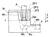
そして、これらのように構成された回転切削工具を用いて、切削対象となるブロック状の素型材Wを切削加工して平面部Whとこれに連続する立壁部Wvにより構成される凹凸形状を有する製品を成形するための金型を形成する場合には、図9に参照されるように、型彫盤Mに回転切削工具Tを取付け、型彫盤Mに素型材Wを固定し、素型材Wと回転切削工具Tを相対的に所定の方向に移動させる。図16および図17に示した回転切削工具TB3を型彫盤Mに取付けた場合には、図10および図11に参照されるように、Z方向に関して同じ位置(Zp1)で回転切削工具TB3の回転軸線Cを素型材Wに対してXおよびY方向に平行移動させ、次いで、Z方向に関して順次同じ位置(Zp2,Zp3,・・・・・ Zpn)で回転切削工具TB3の回転軸線Cを素型材Wに対してXおよびY方向に平行移動させ(以下、この切削加工方法を「等高線切削加工方法」という)、最終荒取り形状Fまで切削加工する。型彫盤Mは、固定された素型材Wの外形面を基準面として、回転切削工具Tが基準面からどれだけ進んだかを基に所定形状に形成するよう制御される。素型材Wは、型彫盤の形成精度や回転切削工具の位置精度、切削加工された面の面粗度、素型材の歪量等に基づいて決定された残り代を最終仕上げ形状に加味した最終荒取り形状Fまで、複数設けられたチップ41,46,51の切れ刃によって切削加工された後に、仕上げ切削や放電加工によって製品を成形し得る最終仕上げ形状に仕上げられることにより金型が形成される。
【0008】
ところで、素型材は、加熱することにより金属等の材料を溶融化し、鋳型に鋳込んで冷却して凝固させることによりブロック状の塊とするのが一般的であるが、凝固する際の冷却速度の差から素型材の内部に残留応力が発生する。この残留応力が発生した状態の素型材の内部を切削加工することにより金型を形成すると、素型材は、内部が切削されて残留応力が解放されることにより基準面となる外形が変形する(図6を参照)。そのため、金型を形成する場合には、素型材に仮の基準面を形成し(図5を参照)、ブロック状の素型材の残留応力を除去し得るように最終荒取り形状に残り代を加えた形状まで素型材の内部を荒取り加工し(図6を参照)、この残留応力が除去された素型材の外形に基準面を新たに形成するよう加工し(図7を参照)、その後、最終荒取り形状まで素型材の内部を荒取り加工する(図8を参照)ことが従来から行われていた。
【0009】
【発明が解決しようとする課題】
上記特開平4−63613号公報に開示されたスローアウェイチップにあっては、主切り刃の必要な部分の刃先強度を確保してその欠損を防止しつつ、主切刃の切れ味を向上させると共に、切屑の排出性を向上させて切削抵抗の軽減を図ることができるというものであって、図14や図15に示した回転切削工具TJ1,TJ2と同様に、切削対象Wに平面部Whとこの平面部Whに対して所定の角度を有する立壁部Wvとを連続して形成するように切削加工することはできないものであった。
【0010】
また、図16および図17に示した回転切削工具TJ3にあっては、切削対象Wに平面部Whを形成するように切削加工する場合には、図14に示したチップ41の切れ刃42がその辺の全長にわたって直線状に形成されたような他の従来の回転切削工具と比較して切削負荷が少ない。しかしながら、回転切削工具TJ3は、図16に示すように、平面部Whを形成する場合におけるチップ51の切れ刃52の切削対象Wに接触する長さJhに比べて、図17に示すように、立壁部Wvを形成する場合における切れ刃52の切削対象Wに接触する長さJvが長くなり、これに伴って切削抵抗も増大する。そのため、平面部Whを形成する場合の回転切削工具TJ3の回転軸線C回りの回転駆動速度を立壁部Wvを形成する場合に合わせて低く設定しなければならず、切削速度等の効率を向上させることができないという問題があった。また、立壁部Wvを形成する場合に切れ刃52の接触する長さJvが長くなることに伴って被接触対象Wの切り屑の幅も広くなる。そのために切り屑が設定通りにカールすることが困難となり排出性が低下することとなる。切り屑の排出性が低下すると、チップ51と切削対象Wとの間に切り屑が介在し、回転切削工具TJ3の回転駆動負荷が大きくなって振動が生じたり、切削対象Wの切削表面の品質が低下するという問題があった。
【0011】
さらに、複数のチップ51が設けられた回転切削工具TJ3を回転軸線C回りに回転させて立壁部Wvを形成する場合には、各チップ51の切れ刃52によって断続的に切削加工することにより、回転切削工具を支持しているアーバが撓む傾向にある。そして、図18および図19に示すように、切削対象Wに接触するチップ51の数は、回転切削工具TJ3の回転軸線C回りの回転位相によって異なり、したがって切削負荷も異なることになる。すなわち、切削対象Wに接触するチップ51の数が多い場合には切削負荷も瞬間的に大きくなり、また、切削対象Wに接触するチップ51の数が少ない場合には切削負荷も瞬間的に減少する。このように切削負荷の瞬間的な変化も、回転切削工具TJ3が取付けられているアーバA等(図9を参照)を撓ませる原因となる。
このようにしてアーバAが撓むと、その反力も加わってチップ51の切れ刃52の切削対象Wに対する切り込み量が大きく変化し、切削対象Wの切削表面に切れ刃の食い込み形状が発生して面粗度が悪化したり、チップ51の切れ刃52に欠損が生じる等の問題があった。
【0012】
そして、回転切削工具を用いてブロック状の素型材から金型を形成する際に、上述したように瞬間的に切削抵抗が変化することによって面粗度が悪化する場合には、加味する残り代の量を多く設定しなければならず、最終仕上げ形状や最終荒取り形状のような形成しようとする形状と、この形状に残り代を加味した形状との差が大きいために金型を形成するための手間がかかり、効率が悪いという問題があった。
【0013】
本発明は、上記問題に鑑みてなされたもので、簡単な構成で切削対象を切削加工して平面部を形成する場合と立壁部を形成する場合の切削負荷が大きく変化しないようにすることができ、もって、切削効率の向上を図ることができるスローアウェイチップならびに回転切削工具を提供することを目的とする。
また、本発明は、金型の形成しようとする形状に加味する残り代を小さく設定することができ、もって、効率よく金型を形成することができる金型形成方法を提供することを目的とする。
【0014】
【課題を解決するための手段】
本発明の請求項1に係るスローアウェイチップは、上記目的を達成するため、回転切削工具に含まれるチップボデーに対して着脱可能に取付けられ、チップボデーを回転軸線回りに回転駆動すると共に回転軸線を平行移動させることにより、切削対象に平面部とこの平面部に対して所定の角度を有する立壁部とを連続して形成することが可能なように切削加工するスローアウェイチップであって、所定の長さを有する第1切れ刃と、回転軸線に関して第1切れ刃の径方向外側に第1切れ刃と連続するように配置され、第1切れ刃の長さよりも小さい曲率半径を有するように形成された第2切れ刃と、チップボデーに取付けられた際に、前記第1切れ刃に所定の切込み角が形成されると共に、前記第2切れ刃がチップボデーの外周から突出するように、チップボデーの支持面と衝合する側面と、を備えたことを特徴とするものである。
【0015】
本発明の請求項2に係るスローアウェイチップは、上記目的を達成するため、請求項1に記載の発明において、前記第1切れ刃と第2切れ刃とをすくい面の複数辺に形成することを特徴とするものである。
【0016】
本発明の請求項3に係るスローアウェイチップは、請求項1または2に記載の発明において、回転切削工具が取付けられたアーバの撓みを防止する押え部を、回転軸線に関して第1切れ刃の径方向内側に連続して配置したことを特徴とするものである。
【0017】
本発明の請求項4に係る回転切削工具は、上記目的を達成するため、回転軸線回りに回転駆動されると共に、回転軸線を平行移動させることにより、切削対象に平面部とこの平面部に対して所定の角度を有する立壁部とを連続して形成することが可能なように切削加工する回転切削工具であって、チップボデーに、所定の長さおよび切込み角を有する第1切れ刃と、回転軸線に関して第1切れ刃の径方向外側に第1切れ刃と連続するように配置され、第1切れ刃の長さよりも小さい曲率半径を有すると共にその外周から突出するように形成された第2切れ刃と、 回転軸線に関して第1切れ刃の径方向内側に連続して配置され、回転切削工具が取付けられたアーバの撓みを防止する押え部と、を一体に形成したことを特徴とするものである。
【0018】
本発明の請求項5に係る金型形成方法は、上記目的を達成するため、回転切削工具によりブロック状の素型材を平面部とこの平面部に対して連続し所定の角度を有する立壁部とにより構成された荒取り形状まで荒取り加工する金型形成方法であって、所定の長さおよび切込み角を有する第1切れ刃と、回転軸線に関して第1切れ刃の径方向外側に第1切れ刃と連続するように配置され、第1切れ刃の長さよりも小さい曲率半径を有すると共にその外周に突出するように形成された第2切れ刃と、回転軸線に関して第1切れ刃の径方向内側に連続して配置され、回転切削工具が取付けられたアーバの撓みを防止する押え部と、を有する回転切削工具を用意し、該回転切削工具を回転軸線回りに回転駆動しながら素型材に対して所定の切込量を有する状態でその回転軸線を平行に移動させ、切削抵抗により回転切削工具に横振れが発生した場合に、前記押さえ部を前記素型材の平面部に接触させることを特徴とするものである。
【0019】
本発明の請求項1に係るスローアウェイチップでは、チップボデーの支持面と衝合する側面により、第1切れ刃が所定の切込み角を形成し、少なくとも第1切れ刃の外側に連続して配置された第2切れ刃がチップボデーの外周から突出するように、チップボデーに取付けらる。回転切削工具を回転軸回りに回転駆動させた状態で、所定の切り込み量で回転軸線を平行移動させて切削対象に平面部とこの平面部に対して所定の角度を有する立壁部とを連続して形成する。第1切れ刃が所定の切り込み角を形成し、これに連続して外側に形成された第2切れ刃が曲率半径を有していることにより、切削対象に平面部を形成する場合と、この平面部に対して所定の角度を有する立壁部を連続して形成する場合とにおける切れ刃の切削対象に対する接触する長さ、およびこれに基づく切削抵抗が両場合で大きく変わることがなく、したがって、平面部を形成する場合の回転切削工具の回転軸線回りの回転駆動速度を、立壁部を形成する場合に合わせて低く設定する必要がない。
【0020】
本発明の請求項2に係るスローアウェイチップでは、請求項1に記載の発明において、第1切れ刃と第2切れ刃とをすくい面の複数辺に形成することにより、一辺の第1および/または第2切れ刃の切削能力が低下した場合には、スローアウェイチップを新たなものに交換することなく、異なる辺の第1および第2切れ刃によって切削対象を切削加工するように向きを変えて取付ける。
【0021】
本発明の請求項3に係るスローアウェイチップでは、請求項1または2に記載の発明において、押え部を回転軸線に関して第1切れ刃の径方向内側に連続して配置したことにより、回転切削工具が取付けられたアーバの撓みを防止する。
【0022】
本発明の請求項4に係る回転切削工具では、チップボデーに、所定の長さおよび切込み角を有する第1切れ刃と、回転軸線に関して第1切れ刃の径方向外側に第1切れ刃と連続するように配置され、第1切れ刃の長さよりも小さい曲率半径を有すると共にその外周から突出するように形成された第2切れ刃と、回転軸線に関して第1切れ刃の径方向内側に連続して配置され、回転切削工具が取付けられたアーバの撓みを防止する押え部と、を一体に形成したことにより、回転切削工具を回転軸回りに回転駆動させた状態で、所定の切り込み量で回転軸線を平行移動させて切削対象に平面部とこの平面部に対して所定の角度を有する立壁部とを連続して形成する際に、切削対象に平面部を形成する場合と、この平面部に対して所定の角度を有する立壁部を連続して形成する場合とにおける切れ刃の切削対象に対する接触する長さ、およびこれに基づく切削抵抗が両場合で大きく変わることがなく、したがって、平面部を形成する場合の回転切削工具の回転軸線回りの回転駆動速度を、立壁部を形成する場合に合わせて低く設定する必要がない。そして、立ち壁部を形成する際に、切削抵抗の変化によって回転切削工具が取付けられたアーバが撓むのを、押さえ部が切削対象の表面に接触することにより、アーバの撓みを防止して切削対象の表面に傷が付くのを阻止する。
【0023】
本発明の請求項5に係る金型形成方法では、回転切削工具を回転軸回りに回転駆動させた状態で、所定の切り込み量で回転軸線を平行移動させて、回転切削工具によりブロック状の素型材を平面部とこの平面部に対して連続し所定の角度を有する立壁部とにより構成された荒取り形状まで荒取り加工する。第1切れ刃が所定の切り込み角を形成し、これに連続して外側に形成された第2切れ刃が曲率半径を有していることにより、切削対象に平面部を形成する場合と、この平面部に対して所定の角度を有する立壁部を連続して形成する場合とにおける切れ刃の切削対象に対する接触する長さ、およびこれに基づく切削抵抗が両場合で大きく変わることがない。また、第1切れ刃と連続する押え部備えて切削抵抗により回転切削工具に横振れが発生した場合に、前記押さえ部を前記素型材の平面部に接触させることにより、
切削対象に立壁部を形成する際に切削抵抗を受けて回転切削工具を支持するアーバが撓む傾向にあるが、押え部が切削対象の表面を押えてアーバの撓みを防止するため、回転工具を支持するアーバの撓みや切削対象の表面の傷付きが防止される。このため、回転切削工具を支持するアーバが撓むことによる面粗度の悪化が抑止される。したがって、形成しようとする形状に加味する残り代を大きく設定する必要がない。
【0024】
【発明の実施の形態】
本発明のスローアウェイチップの実施の一形態を、主に図1〜図3に基づいて詳細に説明する。図において同一符号は同一部分または相当部分とする。
本発明のスローアウェイチップ1は、概略、回転切削工具Tに含まれるチップボデーBに対して着脱可能に取付けられ、チップボデーBを回転軸線C回りに回転駆動すると共に回転軸線Cを平行移動させることにより、切削対象Wに平面部Whとこの平面部Whに対して所定の角度を有する立壁部Wvとを連続して形成することが可能なように切削加工するスローアウェイチップ1であって、所定の長さを有する第1切れ刃11と、回転軸線Cに関して第1切れ刃11の径方向外側に第1切れ刃11と連続するように配置され、第1切れ刃11の長さL1よりも小さい曲率半径R1を有するように形成された第2切れ刃12と、チップボデーBに取付けられた際に前記第1切れ刃11に所定の切込み角θ3が形成されると共に、第2切れ刃12がチップボデーBの外周から突出するように、チップボデーBの支持面34,35と衝合する側面14,15と、を備えたものである。
【0025】
チップボデーBは、型彫盤MのアーバまたはコレットA(図9を参照)に取付けられて回転切削工具Tを構成し、回転軸線C回りに回転駆動されながら所定の切込み量で回転軸線Cが切削対象Wと相対的に平行移動される。チップボデーBには、スローアウェイチップ1によって切削対象Wを切削加工する際に、各スローアウェイチップ1と切削対象Wとの間にクーラントを供給するための通路32がチップポケット33に開口するように設けられている。チップボデーBには、スローアウェイチップ1を支持するための支持面34,35が周方向に等間隔で複数(図3に示した実施の形態では5箇所)配置形成されており、図2および図3に示すように、各スローアウェイチップ1をそれぞれ取付け固定するための手段としてのくさび機構30が設けられている。チップボデーBに対してスローアウェチップ1を取付け固定するための手段は、くさび機構30に限定されることなく、例えば図1中の鎖線で示されているように、スローアウェチップ1の略中央に孔31を形成し、この孔31にビス等の締結部材(図示は省略する)を挿通して締めつけることによってスローアウェチップ1をチップボデーBに取付け固定する等、他の取付け固定手段を採用することもできる。
【0026】
図1に示すように、スローアウェイチップ1は、超硬合金等の公知の素材を平板状に形成したもので、厚さ方向に対向する面のうちのチップボデーBの回転駆動される方向前方に配置される側の面がすくい面10を構成する。すくい面10は、この実施の形態の場合、略四角または八角形等、多角形となるように形成されている。また、スローアウェイチップ1の第1および第2切れ刃11,12が形成された辺の側面16,17は、すくい面10に対して鋭角となるように所定の角度で傾斜するよう形成されており、逃げ面を構成している。すなわち、すくい面10と逃げ面16,17との間の稜線第1切れ刃11が形成されると共に、この第1切れ刃11の、チップボデーBに取付けられたときにその回転軸線Cに関して径方向外側に配置される側に連続して第2切れ刃12が形成されている。
【0027】
スローアウェイチップ1の第2切れ刃12と対角線上に位置する角部13をはさんで隣接する2つの側面14,15は、チップボデーBの支持面34,35と衝合するよう形成されている。側面14,15が支持面34,35と衝合されることにより、スローアウェイチップ1は、第1切れ刃11が回転軸線Cに直交する面に対して所定の切り込み角θ3を形成すると共に、すくい面が所定のアキシャルレーキθ1およびラジアルレーキθ4を形成する等、設定された所定の姿勢に位置決めされ、この状態でくさび機構30によって取付け固定される。また、スローアウェイチップ1の回転軸線Cの径方向の長さ(幅)は、チップボデーBに位置決め固定された際に、少なくとも第2切れ刃12がチップボデーBの径方向外側に突出するよう設定されている。
【0028】
この実施の形態の場合、第1切れ刃11の、チップボデーBに取付けられたときにその回転軸線Cに関して径方向内側に配置される部分には、わずかな曲率半径を有するコーナ18を介して連続し、回転軸線Cに直交する面に対して所定の切り込み角を有するように、長さL2を有する副切れ刃19が形成されている。副切れ刃19は、回転軸線Cに直交する面に対して所定の切り込み角を有していることにより、その径方向内側端と切削対象Wの表面との間にわずかな間隔L3が形成される。この場合にあっては、図4に示すように、回転切削工具Tを公転させながらZ方向に移動させることによって、金型を形成するだけでなく、例えば回転切削工具の旋回径Dt以上の径Dwを有するの孔Whを形成するような所謂ヘリカル加工を行うこともできる。
【0029】
さらに、この実施の形態では、スローアウェイチップ1の第2切れ刃から連続する側辺20は、切削対象Wに形成する立壁部Wvと干渉しないように、回転軸線Cに関して径方向内側にわずかに傾斜するよう形成されており、この側辺20の端部とスローアウェイチップ1の最大旋回径を形成する径方向最外側との間にはわずかな間隔L4が形成されている。
【0030】
なお、本発明におけるスローアウェイチップ1は、すくい面10の一辺にのみ第1切れ刃11を形成することに限定されることなく、各辺に所定の長さL1および切込み角θ3を有するように第1切れ刃11を形成することができ、これと同様に、コーナ18を介して副切れ刃19を各辺にそれぞれ形成することもできる。この場合にあっては、副切れ刃19のにげ面を構成する側面24が側面14と同様にチップボデーBの支持面34と衝合される衝合面として機能し得るように形成されていることが望ましい。このように構成することにより、一辺の第1および/または第2切れ刃11,12の切削能力が低下した場合には、スローアウェイチップ1を新たなものに交換することなく、異なる辺の第1および第2切れ刃11,12によって切削対象Wを切削加工するように向きを変えて取付けることができる。
【0031】
また、本発明では、平面部Whおよび立壁部Wvは、それぞれ、主に第1および第2切れ刃11,12によって切削加工されるため、素型材Wの切り屑がカールしやすい幅に形成するように、すなわち、切り屑の排出性を向上させることができるように、第1切れ刃の長さL1および第2切れ刃の曲率半径R1を任意に設定することができる。
さらに、本発明のスローアウェイチップ1は、上述した実施の形態に限定されることなく、例えばすくい面10の形状が三角形または六角形等、四角形または八角形以外の多角形となるように成形することもできる。
【0032】
図18,19に示したように、回転位相によって切削対象の立ち壁部を切削加工するチップ51の数が異なる回転切削工具によって断続的に切削加工して立ち壁部を形成する場合に、切削抵抗の違いによってアーバAが撓む傾向にあるが、本発明のスローアウェイチップ1は、副切れ刃19を形成することで、アーバAの撓みを抑制する効果があり、後述するように押え部として機能する。この場合においては、副切れ刃19の径方向内側端と切削対象Wの表面との間に形成される間隔L3を極力小さくすることが望ましい。
【0033】
上述した実施の形態においては、チップボデーBに着脱可能に取付けられるスローアウェイチップ1の場合によって説明してきたが、本発明はこの実施の形態に限定されることなく、以上に説明したように第1および第2切れ刃11,12等が形成されたチップを溶接或はろう付け等によってチップボデーBに固定し、あるいは、以上に説明したように形成された第1および第2切れ刃11,12等をチップボデーBに一体に形成した所謂ソリッドタイプの回転切削工具とすることもできる(図示は省略する)。
【0034】
次に、本発明の金型形成方法の実施の一形態を、上述したように構成されたスローアウェイチップ1をチップボデーBに取付けてなる回転切削工具Tを用いた場合によって詳細に説明する。
本発明の金型形成方法は、概略、切削対象であるブロック状の素型材Wを回転切削工具Tにより平面部Whとこの平面部Whに対して連続し所定の角度を有する立壁部Wvとにより構成された荒取り加工する金型形成方法であって、所定の長さL1および切込み角θ3を有する第1切れ刃11と、回転軸線Cに関して第1切れ刃11の径方向外側に第1切れ刃11と連続するように配置され、第1切れ刃11の長さL3よりも小さい曲率半径R1を有すると共にその外周に突出するように形成された第2切れ刃12と、回転軸線Cに関して第1切れ刃11の径方向内側に連続して配置され、回転切削工具Tが取付けられたアーバAの撓みを防止する押え部19と、を有する回転切削工具を用意し、この回転切削工具Tを回転軸線C回りに回転駆動しながら、素型材Wに対してZ方向に所定の切込量を有する状態でその回転軸線CをX,Y方向に平行に移動させ、切削抵抗により回転切削工具Tに横振れが発生した場合に、押さえ部19を素型材Wの平面部Whに接触させるものである。
【0035】
図9に示すように、型彫盤Mは、アーバまたはコレットAに回転切削工具Tが取付けられると共に、切削対象となる素型材Wが支持されており、回転切削工具Tと素型材Wとが相対的に移動可能となっている。この実施の形態では図10および図11に示すように、回転切削工具Tは、素型材Wの表面を所定の切込み量だけ切削加工するように回転駆動されながらZ方向に前進され、このZ方向の位置上でXおよびY方向に回転軸線Cを往復して平行移動させるように加工経路Pが制御される。上述したように、回転切削工具Tが副切れ刃19を有する場合には、回転切削工具Tを回転駆動しながら素型材Wの表面に対して所定の切り込み量までZ方向に移動させて切削加工を開始させることもできる。
【0036】
金型を形成する際には、最初に素型材Wの表面を切削して、図5に示すように、素型材Wの各外形面を仮基準面SF1となるように形成する。次いで、図10および図11に示すように、回転工具Tを回転起動しながら、その回転軸線Cを最終荒取り形状Fに応じてXおよびY方向に位置Zp1上で往復平行移動させる。そして、位置Zp1上での切削加工が完了すると、回転切削工具は、再び所定の切り込み量だけZ方向に前進移動してZ方向に関して順次同じ位置(Zp2,Zp3,・・・・・ Zpn)でXおよびY方向に回転軸線の平行移動を繰り返す等高線切削加工方法により、素型材Pの内部を最終荒取り形状Fに残り代αを加えた形状Fαまで一旦切削加工する。
【0037】
素型材Wは、内部が切削加工されることによって残留応力から解放されて、図6に示すように仮の基準面SF1が形成された状態から変形することとなる。そこで、図7に示すように、最終荒取り形状Fに残り代αを加えた形状Fαまで一旦切削加工して残留応力を除去した後に、素型材Wの外形面を切削加工して新たな基準面SF2を形成し、図8に示すように、基準面SF2を型彫盤Mに支持して基準面SF2に基づいて最終荒取り形状Fまで素型材Wの内部を再度等高線切削加工方法により荒取り加工する。残留応力を除去した後に形成された新たな基準面SF2に基づいて最終荒取り形状Fまで切削加工するために、素型材Wの歪量も最終仕上げ形状に加味する必要がない。
【0038】
ここで、図10に示した一点鎖線は回転切削工具Tの回転軸線CのX,Y方向の移動軌跡、すなわち加工経路Pを示したものである。加工経路P1およびP2では主に第1切れ刃11によって素型材Wに平面切削加工が行われて平面部Whが形成され、加工経路P3では第1切れ刃に加えて第2切れ刃によって加工経路P1およびP2で形成された平面部Whに対して所定の角度を有する立壁部Wvが平面部Whと連続するように形成される。図12に示すように、平面部Whを形成する場合のスローアウェイチップ1の第1および第2切れ刃11,12の素型材Wに接触している長さをKhとし、図13に示すように、立壁部Wvを形成する場合の第1および第2切れ刃11,12の素型材Wに接触している長さをKvとして、両場合における接触長さの比の例を具体的な数値で示すと、次式(1)の通りとなる。
Kh:Kv=1:1.1 ・・・・・・ (1)
そして、両場合における接触長さによる切削負荷の比の例を具体的な数値で示すと、次式(2)の通りとなる。
Kh:Kv=1:1.2〜1.3 ・・・・・・ (2)
【0039】
一方、図16に示したように、すくい面がほぼ円形状に形成された従来のスローアウェイチップ51と比較するとにあっては、平面部Whを形成する場合の切れ刃の素型材Wに接触している長さをJhとし、図17に示すように、立壁部Wvを形成する際に切れ刃の素型材Wに接触している長さをJvとして、両場合における接触長さの比の例を具体的な数値で示すと、次式(3)の通りとなる。
Jh:Jv=1:1.8 ・・・・・・ (3)
そして、両場合における接触長さによる切削負荷の比の例を具体的な数値で示すと、次式(4)の通りとなる。
Jh:Jv=1:1.6〜1.7 ・・・・・・ (4)
【0040】
本発明によるスローアウェイチップ1と図16および図17に示された従来のスローアウェイチップ51との立壁部Wvを形成する際の切削負荷を比較すると、Kh=Jhと仮定した場合、本発明によるスローアウェイチップの切削負荷が最低で1.2であるのに対して、従来のスローアウェイチップの切削負荷が最大で1.7である。この数値から、本発明によるスローアウェイチップの切削負荷を従来のスローアウェイチップの切削負荷に対して最大で約70パーセントに低減することができる。したがって、平面部Whを形成する場合の回転切削工具Tの回転軸線C回りの回転駆動速度を立壁部Wvを形成する場合に合わせて低く設定する必要性も低減される。
【0041】
さらに、立壁部Wvを形成するときには、回転工具Tが切削抵抗の変化により回転軸Cに対して径方向の抵抗を受けアーバーAが撓み、所謂横振れが発生する傾向にある。しかしながら、本発明では、アーバーAが撓みそうになると、副切れ刃19が切削対象Wの平面部Wvに接触することにより押え部として機能しアーバーA等の撓みを抑制して横振れをほぼ無くすことができる。また、切削対象Wの平面部Wvに接触した副切れ刃19は、素型材Wの表面をわずかに切削することととなり、その表面にへこみ等の傷が付くのを阻止することができる。
【0042】
そして、本発明では、上述したように従来の技術と比較して切削抵抗が低減し、アーバーA等の撓みが抑制されて横振れがなくなるために、切削対象Wの切削表面に切れ刃の食い込み形状を発生させることがなく、素型材の表面の面粗度が格段に向上する。したがって、上述した実施の形態では、回転切削工具Tを用いてブロック状の素型材Wから金型を形成する際に、切削加工された表面の面粗度を除いた、型彫盤Mの形成精度や回転切削工具Tの位置精度、素型材Wの歪量に基づいて残り代αの量を設定し所望する形状に加味するだけで済むので、残り代αの量を低減させることができる。すなわち、最終荒取り仕上げ形状Fを最終仕上げ形状に近づけることができるので、金型を効率よく形成することができる。
【0043】
【発明の効果】
請求項1の発明によれば、チップボデーの支持面と衝合する側面を備えたことにより、スローアウェイチップは、第1切れ刃が所定の切込み角を形成し、少なくとも第1切れ刃の外側に連続して配置された第2切れ刃がチップボデーの外周から突出するように、チップボデーに取付けらる。そして、第1切れ刃が所定の切り込み角を形成し、これに連続して外側に形成された第2切れ刃が曲率半径を有していることにより、切削対象を切削加工して平面部を形成する場合と立壁部を形成する場合の切削負荷が大きく変化しないようにすることができ、もって、切削効率の向上を図ることができるスローアウェイチップを提供することができる。
【0044】
請求項2の発明によれば、請求項1に記載の発明において、前記第1切れ刃と第2切れ刃とをすくい面の複数辺に形成することにより、一辺の第1および/または第2切れ刃の切削能力が低下した場合には、スローアウェイチップを新たなものに交換することなく、異なる辺の第1および第2切れ刃によって切削対象を切削加工するように向きを変えて取付けることができるスローアウェイチップを提供することができる。
【0045】
請求項3の発明によれば、請求項1または2に記載の発明において、回転切削工具が取付けられたアーバの撓みを防止する押え部を、回転軸線に関して第1切れ刃の径方向内側に連続して配置したことにより、回転工具の撓みや切削対象の表面の傷付きを防止することができ、また、所謂ヘリカル加工を行うこともできるスローアウェイチップを提供することができる。
【0046】
請求項4の発明によれば、チップボデーに、所定の長さおよび切込み角を有する第1切れ刃と、回転軸線に関して第1切れ刃の径方向外側に第1切れ刃と連続するように配置され、第1切れ刃の長さよりも小さい曲率半径を有すると共にその外周から突出するように形成された第2切れ刃と、回転軸線に関して第1切れ刃の径方向内側に連続して配置され、回転切削工具が取付けられたアーバの撓みを防止する押え部と、を一体に形成したことにより、回転切削工具を回転軸回りに回転駆動させた状態で、所定の切り込み量で回転軸線を平行移動させて切削対象に平面部とこの平面部に対して所定の角度を有する立壁部とを連続して形成する際に、平面部を形成する場合の回転切削工具の回転軸線回りの回転駆動速度を、立壁部を形成する場合に合わせて低く設定する必要がなく、しかも、立ち壁部を形成する際に、切削抵抗の変化によって回転切削工具が取付けられたアーバが撓むのを防止して切削対象の表面に傷が付くのを阻止することができる回転切削工具を提供することができる。
【0047】
請求項5の発明によれば、所定の長さおよび切込み角を有する第1切れ刃と、回転軸線に関して第1切れ刃の径方向外側に第1切れ刃と連続するように配置され、第1切れ刃の長さよりも小さい曲率半径を有すると共にその外周に突出するように形成された第2切れ刃と、回転軸線に関して第1切れ刃の径方向内側に配置され第1切れ刃と連続する副切れ刃と、回転軸線に関して第1切れ刃の径方向内側に連続して配置され、回転切削工具が取付けられたアーバの撓みを防止する押え部と、を有する回転切削工具を用意し、該回転切削工具を回転軸線回りに回転駆動しながら素型材に対して所定の切込量を有する状態でその回転軸線を平行に移動させ、切削抵抗により回転切削工具に横振れが発生した場合に、前記押さえ部を前記素型材の平面部に接触させることにより、切削対象に平面部を形成する場合と、この平面部に対して所定の角度を有する立壁部を連続して形成する場合とにおける第1および第2切れ刃の切削対象に対する接触する長さ、およびこれに基づく切削抵抗が両場合で大きく変わることがなく、また、回転工具を支持するアーバの撓みや切削対象の表面の傷付きを止するため、回転切削工具を支持するアーバが撓むことによる面粗度の悪化が抑止される。したがって、形成しようとする形状に加味する残り代を小さく設定することができ、もって効率よく金型を形成することができる金型形成方法を提供することができる。
【図面の簡単な説明】
【図1】本発明のスローアウェイチップの実施の一形態を示す正面図である。
【図2】チップボデーに取付けられた状態の本発明のスローアウェイチップの側面図である。
【図3】スローアウェイチップが取付けられたチップボデーの正面図である。
【図4】本発明の回転切削工具によりヘリカル加工を行う場合の説明図である。
【図5】切削対象に仮の基準面を形成した状態を示す説明図である。
【図6】切削対象の内部を切削加工したことにより切削対象が変形した状態を示す説明図である。
【図7】変形した切削対象に新たに基準面を形成した状態を示す説明図である。
【図8】切削対象を最終荒取り形状まで切削加工した状態を示す説明図である。
【図9】本発明の回転切削工具が適用される型彫盤の正面図である。
【図10】回転切削工具の加工経路を示す平面図である。
【図11】等高線切削加工方法を説明するための図10の正面図である。
【図12】本発明の回転切削工具により平面部を形成する状態を示す説明図である。
【図13】本発明の回転切削工具により立壁部を形成する状態を示す説明図である。
【図14】従来の回転切削工具の一例を示す説明図である。
【図15】従来の回転切削工具の別の例を示す説明図である。
【図16】従来の回転切削工具により平面部を形成する状態を示す説明図である。
【図17】従来の回転切削工具により立壁部を形成する状態を示す説明図である。
【図18】切削対象に接触するチップの数が、回転切削工具の回転軸線回りの回転位相によって多い場合を示す説明図である。
【図19】切削対象に接触するチップの数が、回転切削工具の回転軸線回りの回転位相によって図18に示した場合よりも少ない場合を示す説明図である。
【符号の説明】
T 回転切削工具
B チップボデー
C 回転軸線
W 切削対象
Wh 平面部
Wv 立壁部
1 スローアウェイチップ
11 第1切れ刃
12 第2切れ刃
19 副切れ刃[0001]
BACKGROUND OF THE INVENTION
The present invention relates to a throw-away tip, a rotary cutting tool, and a mold forming method, and more particularly, to continuously form a flat portion and a standing wall portion having a predetermined angle with respect to the flat portion on a cutting target. A throw-away tip that is detachably attached to a tip body included in a rotary cutting tool for cutting, a rotary cutting tool, and a method of forming a die by cutting a block-shaped material with a rotary cutting tool It is about.
[0002]
In general, a rotary cutting tool is used when performing a cutting process such as a planing on the surface to be cut. In these rotary cutting tools, the body and cutting blade are formed integrally, the tip on which the cutting blade is formed is fixed to the chip body by welding or brazing, etc., and the throwing blade on which the cutting blade is formed. Some away chips are detachably attached to the chip body by bolts or wedge mechanisms. In general, the throw-away tip is often a plate having a rake face formed in a substantially triangular or quadrangular shape. The cutting edge of these rotary cutting tool inserts or throw-away inserts (hereinafter collectively referred to as "tips") is linear so that it extends over at least one side of the ridgeline between the rake face and the flank face of the insert over almost the entire length of the edge. Is formed.
[0003]
14 to 17 show an example of a conventional rotary cutting tool. The rotary cutting tool TJ1 shown in FIG. 14 is provided such that the
[0004]
On the other hand, the rotary cutting tool TJ2 shown in FIG. 15 is such that the
[0005]
Moreover, as disclosed in JP-A-4-63613, a polygonal flat plate shape is formed, and at least one of the ridge sides of the upper and lower surfaces facing the thickness direction of the plate is provided on at least one of the ridge sides. In the throw-away tip, in which a rake face that reaches the main cutting edge is formed on a side surface disposed around the upper and lower surfaces, the rake face is formed on each side of the rake face. A plurality of constituent surfaces intersecting so as to draw a convex ridge line reaching the main cutting edge is formed in a multi-step shape, and the intersection angle between each of these constituent surfaces and one of the upper and lower surfaces connected to the main cutting edge is mutually There is known a throw-away tip characterized by being set at different angles. The action of the throw-away tip is as follows: “The rake angle in the axial direction of the rake face increases stepwise from the component surface located on the tool tip side toward the component surface located on the tool proximal side. Since the intersecting angles with the upper surface or the lower surface of these constituent surfaces are different from each other, the axial rake angle of the rake surface changes stepwise from the tool tip side to the base end side. The rake angle in the radial direction of the main cutting edge can be reduced by making the crossing angle on the component side located on the tool tip side smaller than the crossing angle on the tool base end side among the component surfaces constituting the rake face. The sharpness is improved by increasing the tip of the tool, and at the same time, the rake angle is increased and the cutting edge hardness is improved on the tool proximal side, while the main cutting edge can be increased by increasing the crossing angle of the component surface on the tool tip side. Of the tool tip side The tip angle is increased and the cutting edge strength is improved, and at the same time, the radial rake angle on the tool base end side is increased and the sharpness is improved. While securing the strength of the necessary part of the main cutting edge, the rake angle in the radial direction and the axial rake angle of the rake face can be partially increased to reduce the cutting resistance of the entire main cutting edge. Or the like.
[0006]
Further, the rotary cutting tool TJ3 shown in FIG. 16 and FIG. 17 is a plate-like shape in which the
[0007]
And using the rotary cutting tool comprised in these, it cuts the block-shaped raw material W used as cutting object, and has the uneven | corrugated shape comprised by the plane part Wh and the standing wall part Wv continuous with this. When forming a mold for molding a product, as shown in FIG. 9, a rotary cutting tool T is attached to a mold carving machine M, a mold material W is fixed to the mold carving machine M, and a mold material is obtained. W and the rotary cutting tool T are relatively moved in a predetermined direction. When the rotary cutting tool TB3 shown in FIGS. 16 and 17 is attached to the mold carving machine M, as shown in FIGS. 10 and 11, the rotary cutting tool TB3 is placed at the same position (Zp1) in the Z direction. The rotational axis C is translated in the X and Y directions with respect to the base material W, and then the rotational axis C of the rotary cutting tool TB3 is sequentially placed at the same position (Zp2, Zp3,... Zpn) with respect to the Z direction. The mold material W is translated in the X and Y directions (hereinafter, this cutting method is referred to as a “contour line cutting method”), and the final roughing shape F is cut. The mold engraving machine M is controlled so as to be formed in a predetermined shape based on how far the rotary cutting tool T has advanced from the reference plane, with the outer surface of the fixed base material W as a reference plane. The base material W takes into account the remaining allowance determined based on the forming accuracy of the die-cutting machine, the positional accuracy of the rotary cutting tool, the surface roughness of the machined surface, the amount of distortion of the base material, and the like in the final finished shape. After cutting up to the final roughing shape F by the cutting edges of a plurality of
[0008]
By the way, the mold material is generally made into a block-like lump by melting a material such as metal by heating, casting into a mold, cooling and solidifying, but the cooling rate when solidifying Residual stress is generated inside the mold material due to the difference between the two. When the mold is formed by cutting the inside of the mold material in a state where the residual stress is generated, the outer shape of the mold material is deformed as a reference surface by cutting the inside and releasing the residual stress ( (See FIG. 6). For this reason, when forming a mold, a temporary reference surface is formed on the mold material (see FIG. 5), and the remaining allowance is added to the final rough shape so that the residual stress of the block-shaped mold material can be removed. Roughing the inside of the mold material to the added shape (see FIG. 6), processing to form a new reference surface on the outer shape of the mold material from which the residual stress has been removed (see FIG. 7), then Conventionally, the inside of the mold material is roughed to the final rough shape (see FIG. 8).
[0009]
[Problems to be solved by the invention]
In the throw-away tip disclosed in the above Japanese Laid-Open Patent Publication No. 4-63613, the sharpness of the main cutting edge is improved while ensuring the edge strength of the necessary portion of the main cutting edge and preventing its chipping. The cutting resistance can be reduced by improving the discharge of chips, and the flat portion Wh is placed on the object to be cut W in the same manner as the rotary cutting tools TJ1 and TJ2 shown in FIGS. Cutting cannot be performed so as to continuously form the standing wall portion Wv having a predetermined angle with respect to the flat surface portion Wh.
[0010]
Further, in the rotary cutting tool TJ3 shown in FIGS. 16 and 17, when cutting is performed so as to form the flat portion Wh on the cutting target W, the
[0011]
Furthermore, when rotating the rotary cutting tool TJ3 provided with a plurality of
When the arbor A is bent in this way, the reaction force is also applied, and the cutting amount of the
[0012]
Then, when forming a die from a block-shaped material using a rotary cutting tool, if the surface roughness deteriorates due to a momentary change in cutting resistance as described above, the remaining allowance to be taken into account Since the difference between the shape to be formed, such as the final finish shape or the final rough shape, and the shape that takes into account the remaining allowance is large, the mold is formed. There was a problem that it took a lot of time and was inefficient.
[0013]
The present invention has been made in view of the above problems, and it is possible to prevent a large change in the cutting load when forming a plane portion and a standing wall portion by cutting a cutting object with a simple configuration. Therefore, an object of the present invention is to provide a throw-away tip and a rotary cutting tool that can improve cutting efficiency.
Another object of the present invention is to provide a mold forming method capable of setting the remaining allowance added to the shape to be formed of the mold small and efficiently forming the mold. To do.
[0014]
[Means for Solving the Problems]
In order to achieve the above object, a throw-away tip according to
[0015]
According to
[0016]
The throw-away chip according to
[0017]
In order to achieve the above object, the rotary cutting tool according to claim 4 of the present invention is driven to rotate around the rotation axis and translates the rotation axis so that the object to be cut is a plane part and the plane part. A rotary cutting tool that performs cutting so that a standing wall portion having a predetermined angle can be continuously formed, the tip body having a first cutting edge having a predetermined length and a cutting angle; The second cutting edge is arranged on the radially outer side of the first cutting edge with respect to the rotation axis so as to be continuous with the first cutting edge, and has a radius of curvature smaller than the length of the first cutting edge and is formed so as to protrude from the outer periphery thereof. With a cutting edge,A presser part that is continuously arranged radially inward of the first cutting edge with respect to the rotation axis and prevents the arbor to which the rotary cutting tool is attached;Are integrally formed.
[0018]
The mold forming method according to claim 5 of the present invention achieves the above object,By rotary cutting toolBlock shaped materialRoughing up to a rough shape consisting of a flat part and a standing wall part that is continuous with the flat part and has a predetermined angle.A mold forming method for processing, wherein a first cutting edge having a predetermined length and a cutting angle, a first cutting edge arranged radially outside the first cutting edge with respect to the rotation axis, A second cutting edge having a radius of curvature smaller than the length of the one cutting edge and formed so as to protrude to the outer periphery thereof;A presser part that is continuously arranged radially inward of the first cutting edge with respect to the rotation axis and prevents the arbor to which the rotary cutting tool is attached;HavePrepare a rotary cutting toolWhile rotating the rotary cutting tool around the rotation axis, the rotation axis is moved in parallel with a predetermined cut amount with respect to the mold material.When the horizontal runout occurs in the rotary cutting tool due to cutting resistance, the pressing portion is brought into contact with the flat portion of the mold materialIt is characterized by this.
[0019]
In the throw-away tip according to
[0020]
According to
[0021]
In the throw-away tip according to
[0022]
According to claim 4 of the present inventionTimesIn the rolling cutting tool, the first cutting edge having a predetermined length and a cutting angle is arranged on the chip body, and the first cutting edge is arranged on the outer side in the radial direction of the first cutting edge with respect to the rotation axis. A second cutting edge having a radius of curvature smaller than the length of the cutting edge and formed so as to protrude from the outer periphery thereof;A presser part that is continuously arranged radially inward of the first cutting edge with respect to the rotation axis and prevents the arbor to which the rotary cutting tool is attached;By integrally formingIn a state where the rotary cutting tool is driven to rotate about the rotation axis, the rotation axis is translated by a predetermined cutting amount, and a plane portion and a standing wall portion having a predetermined angle with respect to the plane portion are continuously connected to the cutting target. The length of contact of the cutting edge with the cutting object in the case where the flat part is formed on the cutting object and the standing wall part having a predetermined angle with respect to the flat part is continuously formed, And the cutting resistance based on this does not change greatly in both cases, and therefore, the rotational drive speed around the rotational axis of the rotary cutting tool when forming the flat portion is set low in accordance with the case where the standing wall portion is formed. There is no need. When the standing wall is formed, the arbor to which the rotary cutting tool is attached is bent due to a change in the cutting resistance, and the pressing part is brought into contact with the surface of the cutting object to prevent the arbor from being bent. Prevents the surface to be cut from being scratched.
[0023]
In the mold forming method according to claim 5 of the present invention, in a state where the rotary cutting tool is rotationally driven around the rotational axis, the rotational axis is translated by a predetermined cutting amount,By rotary cutting toolBlock shaped materialRoughing up to a rough shape consisting of a flat part and a standing wall part that is continuous with the flat part and has a predetermined angle.Process. When the first cutting edge forms a predetermined cutting angle and the second cutting edge formed continuously outside has a radius of curvature, a plane portion is formed on the object to be cut. The length of contact of the cutting edge with the cutting object in the case where the standing wall portion having a predetermined angle with respect to the flat surface portion is continuously formed and the cutting resistance based on the length do not change greatly in both cases. Also, a presser part that is continuous with the first cutting edgeWhen the horizontal runout occurs in the rotary cutting tool due to the cutting resistance, by bringing the pressing portion into contact with the flat portion of the mold material,
The arbor that supports the rotary cutting tool tends to bend when receiving the cutting force when forming the standing wall part on the cutting object, but the presser part presses the surface of the cutting object.Prevent arbor deflectionTherefore, it is possible to prevent the arbor that supports the rotary tool from being bent and the surface to be cut from being damaged. For this reason, the deterioration of the surface roughness due to the bending of the arbor supporting the rotary cutting tool is suppressed. Therefore, it is not necessary to set a large remaining allowance in consideration of the shape to be formed.
[0024]
DETAILED DESCRIPTION OF THE INVENTION
An embodiment of the throw-away tip of the present invention will be described in detail mainly based on FIGS. In the drawings, the same reference numerals denote the same or corresponding parts.
The throw-
[0025]
The tip body B is attached to the arbor or collet A (see FIG. 9) of the mold carving machine M to constitute the rotary cutting tool T, and the rotational axis C is rotated with the predetermined cutting amount while being rotated around the rotational axis C. It is moved in parallel with the cutting object W. In the tip body B, when the cutting target W is cut by the throw-
[0026]
As shown in FIG. 1, the throw-
[0027]
The two
[0028]
In the case of this embodiment, the portion of the
[0029]
Furthermore, in this embodiment, the
[0030]
The throw-
[0031]
Further, in the present invention, the flat surface portion Wh and the standing wall portion Wv are formed by the first and second cutting edges 11 and 12, respectively, so that the chips of the base material W are easily curled. In other words, the length L1 of the first cutting edge and the radius of curvature R1 of the second cutting edge can be arbitrarily set so as to improve the chip dischargeability.
Further, the throw-
[0032]
As shown in FIGS. 18 and 19, when the standing wall portion is formed by cutting intermittently with a rotary cutting tool having different numbers of
[0033]
In the above-described embodiment, the case of the throw-
[0034]
Next, an embodiment of the mold forming method of the present invention will be described in detail by using a rotary cutting tool T in which the throw-
In the mold forming method of the present invention, a block-shaped mold material W to be cut is roughly divided by a rotary cutting tool T.The plane portion Wh and the standing wall portion Wv which is continuous with the plane portion Wh and has a predetermined angle are included.A die forming method for roughing, which includes a first cutting edge 11 having a predetermined length L1 and a cutting angle θ3, and a first cutting edge 11 radially outward of the first cutting edge 11 with respect to the rotation axis C. A second cutting edge 12 which is arranged so as to be continuous and has a radius of curvature R1 smaller than the length L3 of the first cutting edge 11 and which protrudes to the outer periphery thereof;A presser portion 19 which is continuously arranged on the inner side in the radial direction of the first cutting edge 11 with respect to the rotation axis C and prevents the arbor A to which the rotary cutting tool T is attached;HavePrepare a rotary cutting tool.While rotationally driving the rotary cutting tool T around the rotational axis C, the rotational axis C is moved in parallel to the X and Y directions in a state having a predetermined cutting amount in the Z direction with respect to the mold material W,When the horizontal runout occurs in the rotary cutting tool T due to the cutting resistance, the pressing portion 19 is brought into contact with the flat portion Wh of the template material W.Is.
[0035]
As shown in FIG. 9, in the mold carving machine M, a rotary cutting tool T is attached to an arbor or a collet A, and a base material W to be cut is supported, and the rotary cutting tool T and the base material W are separated from each other. It is relatively movable. In this embodiment, as shown in FIGS. 10 and 11, the rotary cutting tool T is advanced in the Z direction while being rotationally driven so as to cut the surface of the base material W by a predetermined depth of cut, and this Z direction. The machining path P is controlled so that the rotational axis C is reciprocated and translated in the X and Y directions on the position. As described above, when the rotary cutting tool T has the
[0036]
When forming the mold, first, the surface of the mold material W is cut, and each outer surface of the mold material W is formed to be a temporary reference surface SF1 as shown in FIG. Next, as shown in FIGS. 10 and 11, while the rotary tool T is started to rotate, the rotational axis C is reciprocally translated in the X and Y directions on the position Zp <b> 1 in accordance with the final rough shape F. When the cutting process on the position Zp1 is completed, the rotary cutting tool again moves forward in the Z direction by a predetermined cutting amount, and sequentially in the same direction (Zp2, Zp3,... Zpn) with respect to the Z direction. The inside of the base material P is once cut to a shape Fα obtained by adding the remaining allowance α to the final roughing shape F by a contour cutting method that repeats parallel movement of the rotation axis in the X and Y directions.
[0037]
The mold material W is released from the residual stress by cutting the inside, and is deformed from the state in which the temporary reference surface SF1 is formed as shown in FIG. Therefore, as shown in FIG. 7, after cutting once to the shape Fα obtained by adding the remaining allowance α to the final roughing shape F to remove the residual stress, the outer surface of the base material W is cut to establish a new standard. A surface SF2 is formed, and as shown in FIG. 8, the reference surface SF2 is supported by the mold carving machine M, and the inside of the mold material W is roughed again by the contour cutting method to the final roughing shape F based on the reference surface SF2. Machining. Since cutting is performed to the final roughing shape F on the basis of the new reference surface SF2 formed after the residual stress is removed, it is not necessary to add the distortion amount of the base material W to the final finished shape.
[0038]
Here, the alternate long and short dash line shown in FIG. 10 indicates the movement path in the X and Y directions of the rotation axis C of the rotary cutting tool T, that is, the machining path P. In the machining paths P1 and P2, the
Kh: Kv = 1: 1.1 (1)
And when the example of ratio of the cutting load by the contact length in both cases is shown by a specific numerical value, it will become as following Formula (2).
Kh: Kv = 1: 1.2 to 1.3 (2)
[0039]
On the other hand, as shown in FIG. 16, in comparison with the conventional throw-
Jh: Jv = 1: 1.8 (3)
And when the example of ratio of the cutting load by the contact length in both cases is shown by a specific numerical value, it will become as following Formula (4).
Jh: Jv = 1: 1.6 to 1.7 (4)
[0040]
Comparing the cutting load when forming the standing wall portion Wv between the throw-
[0041]
Further, when the standing wall portion Wv is formed, the rotary tool T receives a radial resistance with respect to the rotation axis C due to a change in cutting resistance, so that the arbor A is bent, and so-called lateral vibration tends to occur. However, in the present invention, when the arbor A is about to bend, the
[0042]
In the present invention, as described above, the cutting resistance is reduced as compared with the conventional technique, and the deflection of the arbor A or the like is suppressed and the lateral vibration is eliminated. Therefore, the cutting edge bites into the cutting surface of the cutting target W. The surface roughness of the surface of the mold material is remarkably improved without generating a shape. Therefore, in the above-described embodiment, when the mold is formed from the block-shaped mold material W using the rotary cutting tool T, the formation of the mold engraving machine M excluding the surface roughness of the cut surface. The amount of the remaining allowance α can be reduced because the amount of the remaining allowance α is set based on the accuracy, the positional accuracy of the rotary cutting tool T, and the amount of distortion of the mold material W and only added to the desired shape. That is, since the final roughing finish shape F can be brought close to the final finish shape, the mold can be formed efficiently.
[0043]
【The invention's effect】
According to the invention of
[0044]
According to the invention of
[0045]
According to the invention of
[0046]
According to invention of Claim 4, it arrange | positions so that a 1st cutting edge which has predetermined | prescribed length and a cutting angle may be followed by a 1st cutting edge in the radial direction outer side of a 1st cutting edge with respect to a rotation axis on a chip body. A second cutting edge that has a radius of curvature smaller than the length of the first cutting edge and is formed so as to protrude from the outer periphery thereof;A presser part that is continuously arranged radially inward of the first cutting edge with respect to the rotation axis and prevents the arbor to which the rotary cutting tool is attached;By integrally formingIn a state where the rotary cutting tool is driven to rotate about the rotation axis, the rotation axis is translated by a predetermined cutting amount, and a plane portion and a standing wall portion having a predetermined angle with respect to the plane portion are continuously connected to the cutting target. It is not necessary to set the rotational drive speed around the rotation axis of the rotary cutting tool when forming the flat portion to be low when forming the standing wall portion, and the standing wall portion is formed. In this case, it is possible to provide a rotary cutting tool that can prevent the arbor to which the rotary cutting tool is attached from bending due to a change in cutting resistance and prevent the surface to be cut from being damaged.
[0047]
According to invention of Claim 5, it arrange | positions so that a 1st cutting edge which has predetermined length and cutting angle, and a 1st cutting edge may be followed on the radial direction outer side of a 1st cutting edge with respect to a rotating shaft, 1st A second cutting edge having a radius of curvature smaller than the length of the cutting edge and projecting to the outer periphery of the second cutting edge; With a cutting edge,A presser part that is continuously arranged radially inward of the first cutting edge with respect to the rotation axis and prevents the arbor to which the rotary cutting tool is attached;HavePrepare a rotary cutting toolWhile rotating the rotary cutting tool around the rotation axis, the rotation axis is moved in parallel with a predetermined cut amount with respect to the mold material.When the horizontal runout occurs in the rotary cutting tool due to cutting resistance, the pressing portion is brought into contact with the flat portion of the mold materialThus, the length of contact of the first and second cutting edges with respect to the cutting object when the flat part is formed on the cutting object and when the standing wall part having a predetermined angle with respect to the flat part is continuously formed. And the cutting force based on this will not change significantly in both cases.And againSince the bending of the arbor that supports the rotary tool and the scratching of the surface to be cut are stopped, deterioration of the surface roughness due to the deflection of the arbor that supports the rotary cutting tool is suppressed. Therefore, the remaining allowance added to the shape to be formed can be set small, and a mold forming method capable of efficiently forming a mold can be provided.
[Brief description of the drawings]
FIG. 1 is a front view showing an embodiment of a throw-away tip according to the present invention.
FIG. 2 is a side view of the throw-away tip of the present invention attached to the tip body.
FIG. 3 is a front view of a tip body to which a throw-away tip is attached.
FIG. 4 is an explanatory diagram in the case of performing helical machining with the rotary cutting tool of the present invention.
FIG. 5 is an explanatory diagram showing a state in which a temporary reference surface is formed on a cutting target.
FIG. 6 is an explanatory diagram showing a state in which the cutting target is deformed by cutting the inside of the cutting target.
FIG. 7 is an explanatory diagram showing a state in which a reference surface is newly formed on a deformed cutting target.
FIG. 8 is an explanatory diagram showing a state in which a cutting target is cut to a final roughing shape.
FIG. 9 is a front view of a die-cutting machine to which the rotary cutting tool of the present invention is applied.
FIG. 10 is a plan view showing a machining path of the rotary cutting tool.
FIG. 11 is a front view of FIG. 10 for explaining a contour cutting method.
FIG. 12 is an explanatory view showing a state in which a plane portion is formed by the rotary cutting tool of the present invention.
FIG. 13 is an explanatory view showing a state in which a standing wall portion is formed by the rotary cutting tool of the present invention.
FIG. 14 is an explanatory view showing an example of a conventional rotary cutting tool.
FIG. 15 is an explanatory view showing another example of a conventional rotary cutting tool.
FIG. 16 is an explanatory view showing a state in which a plane portion is formed by a conventional rotary cutting tool.
FIG. 17 is an explanatory view showing a state in which a standing wall portion is formed by a conventional rotary cutting tool.
FIG. 18 is an explanatory diagram showing a case where the number of chips that come into contact with the cutting object is large depending on the rotational phase around the rotational axis of the rotary cutting tool.
FIG. 19 is an explanatory diagram showing a case where the number of chips that come into contact with the cutting object is smaller than that shown in FIG. 18 due to the rotational phase around the rotational axis of the rotary cutting tool.
[Explanation of symbols]
T Rotary cutting tool
B Chip body
C axis of rotation
W Cutting object
Wh plane part
Wv vertical wall
1 Throw away chips
11 First cutting edge
12 Second cutting edge
19 Sub cutting edge
Claims (5)
所定の長さを有する第1切れ刃と、回転軸線に関して第1切れ刃の径方向外側に第1切れ刃と連続するように配置され、第1切れ刃の長さよりも小さい曲率半径を有するように形成された第2切れ刃と、チップボデーに取付けられた際に、前記第1切れ刃に所定の切込み角が形成されると共に、前記第2切れ刃がチップボデーの外周から突出するように、チップボデーの支持面と衝合する側面と、を備えたことを特徴とするスローアウェイチップ。The tip body included in the rotary cutting tool is detachably attached, and the tip body is driven to rotate about the rotation axis and the rotation axis is moved in parallel, so that a plane portion and a predetermined portion with respect to the plane portion are to be cut. A throw-away tip that is cut so as to be able to continuously form a standing wall portion having an angle of
A first cutting edge having a predetermined length and a radius of curvature smaller than the length of the first cutting edge are arranged to be continuous with the first cutting edge radially outside the first cutting edge with respect to the rotation axis. a second cutting edge formed at, when attached to the tip body, a predetermined cutting angle is formed on the first cutting edge, so that the second cutting edge protrudes from the outer periphery of the chip body A throw-away tip comprising: a side that abuts the support surface of the tip body .
チップボデーに、所定の長さおよび切込み角を有する第1切れ刃と、回転軸線に関して第1切れ刃の径方向外側に第1切れ刃と連続するように配置され、第1切れ刃の長さよりも小さい曲率半径を有すると共にその外周から突出するように形成された第2切れ刃と、回転軸線に関して第1切れ刃の径方向内側に連続して配置され、回転切削工具が取付けられたアーバの撓みを防止する押え部と、を一体に形成したことを特徴とする回転切削工具。It is possible to continuously form a plane portion and a standing wall portion having a predetermined angle with respect to the plane portion on the cutting target by being driven to rotate around the rotation axis and moving the rotation axis in parallel. A rotary cutting tool that cuts into
A first cutting edge having a predetermined length and a cutting angle is arranged on the chip body, and is arranged so as to be continuous with the first cutting edge radially outside the first cutting edge with respect to the rotation axis. From the length of the first cutting edge A second cutting edge that has a small radius of curvature and protrudes from the outer periphery thereof , and an arbor that is continuously disposed radially inward of the first cutting edge with respect to the rotation axis and to which the rotary cutting tool is attached. A rotary cutting tool characterized by integrally forming a presser portion for preventing bending .
所定の長さおよび切込み角を有する第1切れ刃と、回転軸線に関して第1切れ刃の径方向外側に第1切れ刃と連続するように配置され、第1切れ刃の長さよりも小さい曲率半径を有すると共にその外周に突出するように形成された第2切れ刃と、回転軸線に関して第1切れ刃の径方向内側に連続して配置され、回転切削工具が取付けられたアーバの撓みを防止する押え部と、を有する回転切削工具を用意し、
該回転切削工具を回転軸線回りに回転駆動しながら素型材に対して所定の切込量を有する状態でその回転軸線を平行に移動させ、切削抵抗により回転切削工具に横振れが発生した場合に、前記押さえ部を前記素型材の平面部に接触させることを特徴とする金型形成方法。 A mold forming method for roughing a block-shaped mold material by a rotary cutting tool up to a rough shape formed by a flat portion and a standing wall portion having a predetermined angle with respect to the flat portion ,
A first cutting edge having a predetermined length and a cutting angle, and a radius of curvature smaller than the length of the first cutting edge, arranged to be continuous with the first cutting edge on the rotational axis in the radial direction of the first cutting edge. And a second cutting edge formed so as to protrude from the outer periphery of the first cutting edge and the inner side in the radial direction of the first cutting edge with respect to the rotation axis to prevent bending of the arbor to which the rotary cutting tool is attached. A rotary cutting tool having a presser part ,
When the rotary cutting tool is driven to rotate around the axis of rotation, the axis of rotation is moved in parallel with a predetermined depth of cut with respect to the mold material, and a lateral runout occurs in the rotary cutting tool due to cutting resistance. The mold forming method , wherein the pressing portion is brought into contact with the flat portion of the mold material .
Priority Applications (1)
| Application Number | Priority Date | Filing Date | Title |
|---|---|---|---|
| JP31746398A JP3676594B2 (en) | 1998-11-09 | 1998-11-09 | Slow away tip, rotary cutting tool, and mold forming method |
Applications Claiming Priority (1)
| Application Number | Priority Date | Filing Date | Title |
|---|---|---|---|
| JP31746398A JP3676594B2 (en) | 1998-11-09 | 1998-11-09 | Slow away tip, rotary cutting tool, and mold forming method |
Publications (2)
| Publication Number | Publication Date |
|---|---|
| JP2000141123A JP2000141123A (en) | 2000-05-23 |
| JP3676594B2 true JP3676594B2 (en) | 2005-07-27 |
Family
ID=18088516
Family Applications (1)
| Application Number | Title | Priority Date | Filing Date |
|---|---|---|---|
| JP31746398A Expired - Lifetime JP3676594B2 (en) | 1998-11-09 | 1998-11-09 | Slow away tip, rotary cutting tool, and mold forming method |
Country Status (1)
| Country | Link |
|---|---|
| JP (1) | JP3676594B2 (en) |
Families Citing this family (9)
| Publication number | Priority date | Publication date | Assignee | Title |
|---|---|---|---|---|
| JP4576723B2 (en) * | 2000-05-30 | 2010-11-10 | 三菱マテリアル株式会社 | Throw-away cutting tool |
| AT5969U1 (en) | 2001-12-21 | 2003-02-25 | Plansee Tizit Ag | MILLING TOOL |
| JP4304935B2 (en) | 2002-03-11 | 2009-07-29 | 三菱マテリアル株式会社 | Cutting tools and throwaway inserts |
| JP3775321B2 (en) | 2002-03-20 | 2006-05-17 | 三菱マテリアル株式会社 | Throw-away inserts and throw-away cutting tools |
| JP4730817B2 (en) * | 2005-06-15 | 2011-07-20 | 日立ツール株式会社 | Blade-replaceable rotary tool |
| AT12004U1 (en) | 2010-02-25 | 2011-09-15 | Ceratizit Austria Gmbh | CUTTING INSERT |
| US9278395B2 (en) * | 2010-10-27 | 2016-03-08 | Fuji Jukogyo Kabushiki Kaisha | Milling insert and milling tip-replacement-type rotary cutting tool |
| CN103143739B (en) * | 2013-03-29 | 2015-09-09 | 哈尔滨理工大学 | For the turnning and milling compound broken line angle of throat sheet in heavy cutting processing |
| JP6151782B2 (en) | 2013-07-18 | 2017-06-21 | 京セラ株式会社 | Cutting insert, cutting tool, and method of manufacturing cut workpiece |
-
1998
- 1998-11-09 JP JP31746398A patent/JP3676594B2/en not_active Expired - Lifetime
Also Published As
| Publication number | Publication date |
|---|---|
| JP2000141123A (en) | 2000-05-23 |
Similar Documents
| Publication | Publication Date | Title |
|---|---|---|
| KR101478695B1 (en) | Cutting insert and cutting tool, and cut workpiece manufacturing method using same | |
| US7862263B2 (en) | Cutting tool with multiple flutes defining different profiles, and method | |
| JP5357202B2 (en) | Cutting insert, milling tool equipped with the same, and cutting method using the same | |
| US8286536B2 (en) | Milling cutter manufacturing method | |
| US5947649A (en) | Reusable type end mill | |
| JP2008279547A (en) | Groove working method and formed rotary cutting tool | |
| JP2005501749A (en) | Steel cutting method for rotationally symmetric surfaces without twisting | |
| CA2657079C (en) | Modular drilling tool and method for the production thereof | |
| WO2012147816A1 (en) | Cutting insert and cutting tool | |
| JP3676594B2 (en) | Slow away tip, rotary cutting tool, and mold forming method | |
| JP5580239B2 (en) | Milling tools | |
| JP2002292515A (en) | End mill for cutting contour line | |
| US20050186036A1 (en) | Method and tool for production of an inner part of a constant-velocity joint | |
| US6984093B1 (en) | Shaft tool with fixedly disposed winglike inserts | |
| JP2002292514A (en) | End mill of small diameter for cutting contour line | |
| CN211028125U (en) | Bottom arc and coarse tooth shape processing cutter for main shaft blade root tongue-and-groove tooth shape | |
| JP2007313590A (en) | Thread cutting tip, and its manufacturing method | |
| JP7075584B2 (en) | Radius end mills, machine tools using them, and design methods and processing methods for radius end mills. | |
| JP3850068B2 (en) | Slow away insert and rotary cutting tool | |
| JP2000263308A (en) | Cutting method | |
| CN101823166A (en) | Molding milling cutter and molding method | |
| RU2041029C1 (en) | Metal slitting or cutting-off side mill | |
| JP3821108B2 (en) | Drill with chip breaker | |
| JPH0524402Y2 (en) | ||
| JP2755678B2 (en) | Cutting tools |
Legal Events
| Date | Code | Title | Description |
|---|---|---|---|
| A977 | Report on retrieval |
Free format text: JAPANESE INTERMEDIATE CODE: A971007 Effective date: 20041112 |
|
| A131 | Notification of reasons for refusal |
Free format text: JAPANESE INTERMEDIATE CODE: A131 Effective date: 20050105 |
|
| A521 | Written amendment |
Free format text: JAPANESE INTERMEDIATE CODE: A523 Effective date: 20050307 |
|
| TRDD | Decision of grant or rejection written | ||
| A01 | Written decision to grant a patent or to grant a registration (utility model) |
Free format text: JAPANESE INTERMEDIATE CODE: A01 Effective date: 20050406 |
|
| A61 | First payment of annual fees (during grant procedure) |
Free format text: JAPANESE INTERMEDIATE CODE: A61 Effective date: 20050428 |
|
| R150 | Certificate of patent or registration of utility model |
Free format text: JAPANESE INTERMEDIATE CODE: R150 |
|
| FPAY | Renewal fee payment (event date is renewal date of database) |
Free format text: PAYMENT UNTIL: 20080513 Year of fee payment: 3 |
|
| FPAY | Renewal fee payment (event date is renewal date of database) |
Free format text: PAYMENT UNTIL: 20090513 Year of fee payment: 4 |
|
| FPAY | Renewal fee payment (event date is renewal date of database) |
Free format text: PAYMENT UNTIL: 20100513 Year of fee payment: 5 |
|
| FPAY | Renewal fee payment (event date is renewal date of database) |
Free format text: PAYMENT UNTIL: 20100513 Year of fee payment: 5 |
|
| S531 | Written request for registration of change of domicile |
Free format text: JAPANESE INTERMEDIATE CODE: R313531 |
|
| FPAY | Renewal fee payment (event date is renewal date of database) |
Free format text: PAYMENT UNTIL: 20100513 Year of fee payment: 5 |
|
| R350 | Written notification of registration of transfer |
Free format text: JAPANESE INTERMEDIATE CODE: R350 |
|
| FPAY | Renewal fee payment (event date is renewal date of database) |
Free format text: PAYMENT UNTIL: 20110513 Year of fee payment: 6 |
|
| FPAY | Renewal fee payment (event date is renewal date of database) |
Free format text: PAYMENT UNTIL: 20110513 Year of fee payment: 6 |
|
| FPAY | Renewal fee payment (event date is renewal date of database) |
Free format text: PAYMENT UNTIL: 20120513 Year of fee payment: 7 |
|
| FPAY | Renewal fee payment (event date is renewal date of database) |
Free format text: PAYMENT UNTIL: 20130513 Year of fee payment: 8 |
|
| FPAY | Renewal fee payment (event date is renewal date of database) |
Free format text: PAYMENT UNTIL: 20140513 Year of fee payment: 9 |
|
| R250 | Receipt of annual fees |
Free format text: JAPANESE INTERMEDIATE CODE: R250 |
|
| R250 | Receipt of annual fees |
Free format text: JAPANESE INTERMEDIATE CODE: R250 |
|
| R250 | Receipt of annual fees |
Free format text: JAPANESE INTERMEDIATE CODE: R250 |
|
| R250 | Receipt of annual fees |
Free format text: JAPANESE INTERMEDIATE CODE: R250 |
|
| R250 | Receipt of annual fees |
Free format text: JAPANESE INTERMEDIATE CODE: R250 |
|
| EXPY | Cancellation because of completion of term |