JP3676584B2 - Well lid for pump installation - Google Patents
Well lid for pump installation Download PDFInfo
- Publication number
- JP3676584B2 JP3676584B2 JP24022398A JP24022398A JP3676584B2 JP 3676584 B2 JP3676584 B2 JP 3676584B2 JP 24022398 A JP24022398 A JP 24022398A JP 24022398 A JP24022398 A JP 24022398A JP 3676584 B2 JP3676584 B2 JP 3676584B2
- Authority
- JP
- Japan
- Prior art keywords
- well
- well lid
- cable
- joint pipe
- casing
- Prior art date
- Legal status (The legal status is an assumption and is not a legal conclusion. Google has not performed a legal analysis and makes no representation as to the accuracy of the status listed.)
- Expired - Fee Related
Links
Images


Description
【0001】
【発明の属する技術分野】
本発明は、例えば深井戸用水中ポンプの設置に用いられるポンプ設置用井戸ふたに関する。
【0002】
【従来の技術】
深井戸用水中ポンプの据え付けは、井戸ケーシングの地上開口を塞ぐ井戸ふたを用いて行われている。
こうした井戸ふたは、井戸ケーシングの地上開口を閉塞する閉塞部に、同閉塞部を挟む井戸ケーシング側と地上側との間を連通する継ぎ手管を形成した構造が用いられる。そして、井戸ケーシングの地上開口から内部へ深井戸用水中ポンプ、同水中ポンプにつながる揚水管の順で挿入し、揚水管端を井戸ふたに形成してある継ぎ手管の入口に接続してから、同井戸ふたで井戸ケーシング端を閉塞することにより、深井戸用水中ポンプが揚水管を介して吊持されるようにしてある。
【0003】
このポンプの設置をなす井戸ふたには、圧力タンクを用いた給水設備の簡素化を図るべく、継ぎ手管に排気弁を取り付けた構造がある。
この排気弁は、継ぎ手管に該継ぎ手管内の圧力変化で開閉する構造が採用され、継ぎ手管の出口から離れた位置に逆止弁を取り付けて圧力タンクとの間を配管すると、無動力で圧力タンクからの圧送に必要な空気補給が行なえるようにしてある。
【0004】
すなわち、排気弁は、ポンプが停止すると、閉止力を失って、大気を吸い込む。すると、逆止弁から井戸水面までの揚水管部分内の水が落ち、同部分内が空気で満たされる。そして、排気弁は、つぎにポンプの始動の際、井戸水面までの空気を大気へ排出する。ついで、排気弁は、内部に満たされる揚水で閉止され、配管内を密閉する。これにより、揚水と一緒に、排気弁から逆止弁までの配管部分を充満している空気が圧力タンク内に圧送される。つまり、ポンプ始動/停止毎に圧力タンクへ空気が補給されるようになる。
【0005】
むろん、継ぎ手管の出口に直接、逆止弁を取り付けると、空気の圧送が無い、通常の揚水だけの圧送が行われる。
従来、こうした排気弁の取付けには、継ぎ手管の一部に台座を形成し、この台座に継ぎ手管内と連通する接続口を形成し、この接続口に排気弁(井戸ふたとは別体部品の弁)に形成されている取付口部をニップルなどの継ぎ手部材を介して接続していた。
【0006】
【発明が解決しようとする課題】
ところで、井戸ふたは、人手作業で井戸ケーシングの地上開口を覆うために、小型/軽量であることが望まれる。しかも、安価であることも望まれる。
しかしながら、継ぎ手部材で井戸ふたに排気弁を固定する構造は、継ぎ手部材を用いるために、井戸ふたの全体は大形になりやすい上、井戸ふたの重量も増加しやすい。しかも、継ぎ手部材が必要となるので、井戸ふたが高価となりやすい。このため、井戸ふたでは、こうした点の改善が要望されている。
【0007】
本発明は上記事情に着目してなされたもので、その目的とするところは、小型/軽量化、さらにはコスト的にも安価ですむポンプ設置用井戸ふたを提供することにある。
【0008】
【課題を解決するための手段】
上記目的を達成するために請求項1に記載したポンプ設置用井戸ふたは、井戸ふた本体の継ぎ手管に弁室を形成し、この弁室内に弁体を収める構造を採用して、井戸ふたと排気弁とを一体化させたことにある。
【0009】
これにより、井戸ふたは、部品間を接続する継ぎ手が必要ないので、小型/軽量となる。しかも、コスト的な負担も軽減(部品点数の削減による)されるので、製品は安価となる。
【0010】
請求項2に記載のポンプ設置用井戸ふたは、さらに上記目的に加え、雨水や異物等の侵入のおそれがないようにポンプからのケーブルを地上に導出させるために、閉塞部に井戸ケーシング内から地上へケーブルを導出させるケーブル取出口を形成し、このケーブル取出口にケーブルとの隙間を埋めるケーブルブッシュを取り付けたことにある。
【0011】
請求項3に記載のポンプ設置用井戸ふたは、さらに井戸ケーシングの地上の端部に直接、載せるだけで、異なる口径の井戸ケーシングに据え付けられるよう、井戸ケーシングの地上端部に載る載置面に、継ぎ手管の端部周囲に同心円状に異口径の井戸ケーシング端と嵌合可能な複数種のケーシングガイドを形成したことにある。
【0012】
請求項4に記載のポンプ設置用井戸ふたは、さらに赤水の発生、錆こぶによる排気弁の動作不良の発生が防止されるよう、井戸ふた本体および排気弁をステンレス材料で形成して、長年の使用でも錆が発生しにくい井戸ふた構造としたことにある。
【0013】
請求項5に記載のポンプ設置用井戸ふたは、さらに追加の加工を必要とせずに、必要に応じて流量計や試験用配管が装着されるよう、継ぎ手管に複数の計測/試験用配管の取付口を形成したことにある。
【0014】
【発明の実施の形態】
以下、本発明を図1ないし図5に示す第1の実施形態にもとづいて説明する。
図1は、本発明が適用された例えば圧力タンク式の給水装置の圧送系を示していて、図1中1は例えば地中深く形成された円筒状の井戸、2は同井戸1の内面壁を形成する筒形の井戸ケーシングである。
【0015】
井戸ケーシング2内には、地上開口からポンプ、例えば深井戸用水中ポンプ3(以下、単に水中ポンプ3という)が挿入されている。
すなわち、水中ポンプ3は、例えば複数の羽根車(図示しない)が収容されたポンプケーシング5の端部に、各羽根車を駆動する水中モータ6を連結して構成してあり、全体が細長の円柱状をなしている。この水中ポンプ3のケーシング上部に形成されている吐出口部7には、上方へ向かって延びる揚水管8が接続してある。この揚水管8の端部が、地上開口を塞ぐよう井戸ケーシング2の地上端部に載せた井戸ふた9に接続され、井戸1内に水中ポンプ3を吊持させている。
【0016】
この井戸ふた9の周辺の構造が図2および図3に示され、さらに該井戸ふた9の単体の構造が図4および図5に示されている。
本発明の要部となる井戸ふた9の構造について説明すれば、図2中10は井戸ふた本体である。井戸ふた本体10は、井戸ケーシング2の地上開口を塞ぐ閉塞部20と、閉塞部20を挟む井戸ケーシング2側と地上側とを連通する継ぎ手管30とを有して形成してある。
【0017】
閉塞部20は、図4にも示されるように中央が上側へ略椀形形状を描いて突き出るように形成され、この椀形形状部21の周りに例えば矩形状のフランジ部22が形成してあり、盤状をなしている。この閉塞部20の底面中央からは、内面にめねじ23aが形成されている短筒状の口体部23が突き出ていて、後述する継ぎ手管30の入口を形成している。この入口に揚水管8の端部がねじ込まれ、水中ポンプ3を吊時している。
【0018】
またこの口体部23の周囲の底面部分からは、該口体部23と同心円状をなして、径の異なる複数の筒部、例えば2つの筒部24a,24bが突き出ている。例えば内側の筒部24aは、口体部23と同等の高さまで突き出ていて、外側の筒部24bは、筒部24bとフランジ部22との間の中間となる高さまで突き出ている。また口体部23と筒部24aとの間、筒部24aと筒部24bとの間、筒部24bとフランジ部22との間は、それぞれ筒部24a、筒部24b、フランジ部22の高さに合せた放射状のリブ壁25a,25b,25cで連結されている。そして、リブ壁25b,25cが異口径の井戸ケーシング端を受ける載置面26a,26bをなし、同載置面26a,26bから突き出る筒部24a,24bの端部分が異口径の井戸ケーシング端に嵌合可能なケーシングガイド27a,27bをなしている。これにより、井戸ふた9は、図2中の実線で示されるように井戸ケーシング2が小口径のときは、内側のケーシングガイド27aに嵌め込むようにして井戸ケーシング端に直接、載せるだけで、水中ポンプ3の重量で、動かないように井戸ケーシング端に据え付けられる。また井戸ケーシング2が大口径のときは、図2中の二点鎖線で示されるように外側のケーシングガイド27bに嵌め込んで、井戸ふた9を井戸ケーシング端に直接、載せれば、井戸ケーシング端に据え付けられる。
【0019】
また閉塞部20には、図2〜図4に示されるように例えばフランジ外周端から椀形形状部21の一部までを長方形状に切欠してなるケーブル取出口28が形成されている。そして、このケーブル取出口28からケーブル類、例えば水中ポンプ3からのケーブルモータケーブル3a、例えば揚水管8に固定してある水位検知用の水中電極29(水位検知子)からのケーブル29aが地上へ導出している。またケーブル取出口28には、図2および図3に示されるようにケーブル3a,29aとの隙間を埋める例えば二つ割り構造のゴム製のケーブルブッシュ28aが脱着可能に嵌められ、外部(地上)から雨水や異物が井戸1へ侵入しないようにしてある。なお、ケーブルブッシュ28aには、図5に示されるように互いに接する一対のブッシュ片28b,28bの縁部に半円形状の切欠部を形成して、ブッシュ片28b,28b間にケーブル挿通用の通孔28cを形成し、ケーブル3a,29を周りから挟み込んで水密にする構造が用いてある。
【0020】
また閉塞部20の上面中央には、閉塞部20と一体な継ぎ手管30が形成してある。すなわち、継ぎ手管30は、例えば閉塞部20の上面から上方へ立ち上がる短管部分31aと同短管部分31bから側方へ延びる短管部分31bとを組み合わせたL字管部が用いてある。そして、短管部分31aの端部が、先に述べた閉塞部20の底面に形成してある口体部23と連通している。また短管部分31bの端部には、接続部をなすフランジ32が装着され、短管部分31bの端部に出口を形成している。この管構造によって、閉塞部20を挟む井戸ケーシング2側と地上側との間を連通する継ぎ手管30の全体を構成している。
【0021】
この継ぎ手管30の一部、例えば短管部分31bの管壁両側には、図4に示されるように計測/試験用配管の取付口として、口径が異なる複数個の取付口部、例えば2個の取付口部33a,33bが形成してある。なお、接続部として、取付口部33a,33bの内面にはめねじが形成してある。そして、このうちの取付口部33aを用いて、継ぎ手管30内の圧力を検知する圧力計34を取り付けてある。なお、図1は圧力計34を縦向きに取り付けた例を示し、図2は圧力計34を横向きに取り付けた例を示してある。もちろん、各取付口部33a,33b共、短管部分31b内に連通していて、不使用の取付口部33bは盲プラグ35で栓する。
【0022】
また継ぎ手管30の一部、例えば短管部分31aと短管部分31bとが交差する部分には、排気弁40が一体に組み付けてある。
この排気弁40の構造に付いて説明すれば、図2および図4中41は、例えば短管部分31aから連続して上方へ延びる短管部分で形成されたボディである。このボディ41の短管部分31a側は、外周側に複数の通孔42aが形成された仕切壁42で仕切ってある。またボディ41の端部は、中央に弁孔43が形成された弁ふた44で蓋されていて、仕切壁42と弁ふた44とで挟まれるボディ41の内部に弁室45を形成している。これにより、継ぎ手管30と一体な弁室45を形成している。なお、46はボディ41と弁ふた44との間に介在されたシール部材である。そして、この弁室45内に弁体として例えば球体47が収められ、継ぎ手管30内の圧力変化にしたがい継ぎ手管30を大気に開閉させる排気弁40を構成している。また弁ふた44の外面には、外部に開口する例えば横向きの大気開放用の口体部48が形成してある。この口体部48には、L型継手管48aを介して、先端が閉塞部20に形成した戻し孔(井戸に開放する孔)に接続されるホース49が接続されていて、口体部48を井戸水面の上方空間に開放させている(大気開放)。このホース構造により、ポンプ始動の際、弁孔43から揚水が導出されることがあっても、井戸1の周囲を濡らさずに井戸1内へ戻せる構造にしてある。但し、50はホース端をL型継手管48aに固定しているホースバンドを示す。
【0023】
こうした井戸ふた9の全体、排気弁40の全体が、錆に強いステンレス材料で形成してある。
またこの井戸ふた9の出口(フランジ32)が、所定の離間距離を保つための配管部材55、逆止弁56、仕切弁57(開閉弁)を介して、給水装置を構成する圧力タンク58の入口58aに接続され、圧力タンク式の給水設備を構成している。そして、この排気弁40を組み込んだ井戸ふた9と配管部材55とを用いた配管構造により、無動力で圧力タンク58に対して、必要な空気補給が行なえるようにしている。
【0024】
すなわち、水中ポンプ3が停止すると、弁孔43は開き、ホース49を通じて、井戸水面の上方の空気を吸い込む。すると、逆止弁56から井戸水面までの揚水管8内の水が落ち、同部分が空気で満たされる。次に水中ポンプ3が始動すると、まず、井戸水面から排気弁40までの配管内の空気が大気へ排出される。続いて球体47が、揚水の圧力により弁孔43に押し付けられる。つまり、排気弁40は、内部に満たされる揚水で閉止される。これにより、揚水と一緒に、排気弁40から逆止弁56までの配管内の空気が圧力タンク58内へ圧送される。
【0025】
こうした無動力の空気補給を実現する井戸ふた9は、継ぎ手管30に弁室45を形成し、この弁室45内に球体47(弁体)を収める構造を採用して、排気弁40を一体化させているので、従来のように部品間を接続するニップル、さらにはニップルと接続する部分を確保する必要がなく、小型/軽量化が図れる。しかも、コスト的な負担も軽減(部品点数の削減による)されるので、井戸ふた9(製品)は安価である
また井戸ふた9のケーブル取出口28には、同ケーブル取出口28を通るケーブル3a,29との隙間を埋めるケーブルブッシュ28aが取り付けてあるので、隙間から雨水や異物等が井戸1内に侵入する心配はなく、井戸1の水質を守ることができる。しかも、ケーブルブッシュ28aは、ケーブル3a,29を周りから挟持するように保持して隙間が無いようにする構造なので、同ブッシュ28aがモータケーブル3a、水中電極29を固定する部材としても機能する。
【0026】
また井戸ふた9は、底面の載置面に異口径の井戸ケーシング端と嵌合可能な複数種のケーシングガイド27a,27bを形成したので、基礎ボルトがなくても、井戸ケーシング2の地上の端部に直接、載せるだけで、容易に異口径の井戸ケーシング2に井戸ふた9を据え付けることができる。
【0027】
また井戸ふた9は、本体全体および排気弁40の全体をステンレス材料で形成したので、長年の使用でも錆が発生しにくく、錆による赤水の発生や錆こぶによる排気弁の動作不良の発生を防ぐことができる。
【0028】
また井戸ふた9には、複数の計測/試験用配管の取付口部33a,33bが形成してあるので、圧力計、流量計や試験用配管は、別途、追加の加工を井戸ふた9に施さずに、直接、同取付口部33に設置することができ、各種計測機器、試験用配管の据え付けが容易である。
【0029】
なお、第1の実施形態では、圧力タンク58を用いた給水装置につなげる場合を例に挙げたが、むろん図6に示す第2の実施形態で示されるように圧力タンクを用いない給水装置にも適用できることはいうまでもない。
【0030】
すなわち、本実施形態は、井戸ふた9の継ぎ手管30に、直接、逆止弁56、仕切り弁57を接続しておき、排気弁40が発揮しない、つまり空気が送り出されないようにしたものである。但し、図6において第1の実施形態と同じ部分には同一符号を付してその説明を省略した。
【0031】
【発明の効果】
以上説明したように請求項1に記載の発明によれば、小型/軽量化、さらにはコスト的にも安価ですむポンプ設置用井戸ふたが提供できる。
請求項2に記載の発明によれば、さらに上記効果に加え、ケーブル取出口と同取出口を通るケーブルとの隙間から、雨水や異物等が井戸内に侵入するのを防ぐことができ、井戸の水質を守ることができるといった効果を奏する。しかも、ケーブルブッシュは、ケーブルを保持する結果となるので、ケーブルを固定する部材としても機能できる利点もある。
【0032】
請求項3に記載の発明によれば、さらに上記効果に加え、基礎ボルトがなくても、井戸ケーシングの地上端部に、ケーシングガイドと組み合うよう、井戸ふたを直接、載せるだけで、容易に異口径の井戸ケーシングに据え付けることができるといった効果を奏する。
【0033】
請求項4に記載の発明によれば、さらに上記効果に加え、長年の使用でも錆が発生しにくい井戸ふた構造となるので、錆による赤水の発生、錆こぶによる排気弁の動作不良の発生を未然に防止できるといった効果を奏する。
【0034】
請求項5に記載の発明によれば、さらに上記効果に加え、別途、追加の加工を井戸ふたに施さずに、直接、井戸ふたに、各種流量計、試験用配管を接続することができ、各種計測機器、試験用配管の据え付けが容易であるといった効果を奏する。
【図面の簡単な説明】
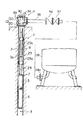
【図1】本発明の第1の実施形態に係るポンプ設置用井戸ふたを、同井戸ふたを用いて水中ポンプを設置したときの状態と共に示す断面図。
【図2】同井戸ふたの周辺を拡大して示す断面図。
【図3】図2中のA〜A線に沿うケーブル取出口の平面図。
【図4】同井戸ふたの各部の構造を説明するための図。
【図5】図2中のB〜B線に沿うケーブル取出口の平面図。
【図6】本発明の第2の実施形態に係る異なる井戸ふたの使用の仕方を説明するための断面図。
【符号の説明】
1…井戸
2…井戸ケーシング
3…深井戸用水中ポンプ(ポンプ)
3a…モータケーブル(ケーブル)
20…閉塞部
26a,26b…載置面
27a,27b…ケーシングガイド
28…ケーブル取出口
28a…ケーブルブッシュ
29…水中電極のケーブル
30…継ぎ手管
33a,33b…取付口部(取付口)
34…圧力計
40…排気管
41…ボディ
43…弁孔
44…弁ふた
45…弁室
47…球体(弁体)。[0001]
BACKGROUND OF THE INVENTION
The present invention relates to a pump installation well lid used for installation of, for example, a deep well submersible pump.
[0002]
[Prior art]
The installation of the deep well submersible pump is carried out using a well lid that closes the ground opening of the well casing.
Such a well lid has a structure in which a joint pipe that communicates between a well casing side sandwiching the closed portion and the ground side is formed in a closed portion that closes the ground opening of the well casing. Then, insert the deep well submersible pump from the ground opening of the well casing in the order of the pumping pipe connected to the submersible pump, and connect the end of the pumping pipe to the inlet of the joint pipe formed in the well lid, By closing the well casing end with the well lid, the deep well submersible pump is suspended through the pumping pipe.
[0003]
The well lid where the pump is installed has a structure in which an exhaust valve is attached to the joint pipe in order to simplify the water supply equipment using the pressure tank.
This exhaust valve employs a structure that opens and closes the joint pipe by pressure change in the joint pipe. When a check valve is installed at a position away from the outlet of the joint pipe and piped between the pressure tank and the pressure tank, no pressure is applied. Air supply necessary for pumping from the tank can be performed.
[0004]
That is, when the pump stops, the exhaust valve loses the closing force and sucks in the atmosphere. Then, the water in the pumping pipe portion from the check valve to the well water surface falls, and the same portion is filled with air. The exhaust valve then discharges the air up to the well surface to the atmosphere when the pump is started. Next, the exhaust valve is closed by pumping water filled inside, and the inside of the pipe is sealed. Thereby, the air filling the piping part from the exhaust valve to the check valve is pumped into the pressure tank together with the pumped water. That is, air is supplied to the pressure tank every time the pump is started / stopped.
[0005]
Of course, when a check valve is attached directly to the outlet of the joint pipe, there is no air pumping and only normal pumping is performed.
Conventionally, for mounting such an exhaust valve, a pedestal is formed on a part of the joint pipe, a connection port communicating with the inside of the joint pipe is formed on the pedestal, and an exhaust valve (a separate part from the well lid) is formed in this connection port. The attachment port portion formed in the valve) is connected via a joint member such as a nipple.
[0006]
[Problems to be solved by the invention]
By the way, the well lid is desired to be small / lightweight in order to manually cover the ground opening of the well casing. Moreover, it is also desired that the price is low.
However, the structure in which the exhaust valve is fixed to the well lid with the joint member uses the joint member, so that the whole well lid tends to be large and the weight of the well lid is likely to increase. Moreover, since a joint member is required, the well lid tends to be expensive. For this reason, the well lid is required to improve these points.
[0007]
The present invention has been made by paying attention to the above circumstances, and an object of the present invention is to provide a well lid for installing a pump which can be reduced in size / weight and can be reduced in cost.
[0008]
[Means for Solving the Problems]
In order to achieve the above object, the well lid for installing a pump according to claim 1 adopts a structure in which a valve chamber is formed in a joint pipe of the well lid body and the valve body is accommodated in the valve chamber. This is because the exhaust valve is integrated.
[0009]
As a result, the well lid is small / lightweight because there is no need for a joint for connecting the parts. Moreover, since the cost burden is reduced (by reducing the number of parts), the product is inexpensive.
[0010]
In addition to the above-mentioned purpose, the well lid for installing a pump according to
[0011]
The well lid for installing a pump according to
[0012]
The well lid for installing a pump according to
[0013]
The well for installing a pump according to
[0014]
DETAILED DESCRIPTION OF THE INVENTION
Hereinafter, the present invention will be described based on a first embodiment shown in FIGS.
FIG. 1 shows a pumping system of, for example, a pressure tank type water supply apparatus to which the present invention is applied. In FIG. 1, 1 is a cylindrical well formed deep in the ground, for example, 2 is an inner wall of the well 1 It is the cylindrical well casing which forms.
[0015]
A pump, for example, a deep well submersible pump 3 (hereinafter simply referred to as a submersible pump 3) is inserted into the
That is, the
[0016]
The structure around the
If the structure of the
[0017]
As shown in FIG. 4, the closing portion 20 is formed so that the center protrudes upward in a substantially bowl shape, and a
[0018]
Further, a plurality of cylindrical portions having different diameters, for example, two
[0019]
Further, as shown in FIGS. 2 to 4, a
[0020]
A
[0021]
As shown in FIG. 4, a plurality of attachment port portions having different diameters, for example, two, are provided on both sides of the
[0022]
Further, an
Referring to the structure of the
[0023]
The
Further, the outlet (flange 32) of the
[0024]
That is, when the
[0025]
The
[0026]
Moreover, since the
[0027]
The
[0028]
Since the
[0029]
In addition, although the case where it connected with the water supply apparatus using the
[0030]
That is, in this embodiment, the
[0031]
【The invention's effect】
As described above, according to the first aspect of the present invention, it is possible to provide a well cover for installing a pump which can be reduced in size / weight and cost-effectively.
According to the invention described in
[0032]
According to the third aspect of the present invention, in addition to the above-described effect, even if there is no foundation bolt, it is easily changed by simply placing the well lid directly on the ground end of the well casing so as to be combined with the casing guide. There is an effect that it can be installed in a well casing having a caliber.
[0033]
According to the invention described in
[0034]
According to the invention described in
[Brief description of the drawings]
FIG. 1 is a sectional view showing a well for installing a pump according to a first embodiment of the present invention together with a state when a submersible pump is installed using the well lid.
FIG. 2 is an enlarged sectional view showing the periphery of the well lid.
FIG. 3 is a plan view of the cable outlet along the line AA in FIG. 2;
FIG. 4 is a view for explaining the structure of each part of the well lid.
FIG. 5 is a plan view of a cable outlet along line B-B in FIG. 2;
FIG. 6 is a cross-sectional view for explaining how to use different well lids according to the second embodiment of the present invention.
[Explanation of symbols]
DESCRIPTION OF SYMBOLS 1 ... Well 2 ... Well casing 3 ... Submersible pump for deep wells (pump)
3a ... Motor cable (cable)
20 ... Blocking
34 ...
Claims (5)
前記継ぎ手管と一体に形成された弁室と該弁室内に収められた弁体とを有して構成され、前記継ぎ手管内の圧力変化にしたがい該継ぎ手管を大気に開閉させる排気弁と
を具備してなることを特徴とするポンプ設置用井戸ふた。A well lid main body configured to have a closed portion that closes the ground opening of the well casing, and a joint pipe that is formed so as to communicate between the well casing side and the ground side that sandwich the closed portion;
A valve chamber formed integrally with the joint pipe and a valve body housed in the valve chamber, and an exhaust valve that opens and closes the joint pipe to the atmosphere according to a pressure change in the joint pipe. A well lid for installing a pump.
Priority Applications (1)
| Application Number | Priority Date | Filing Date | Title |
|---|---|---|---|
| JP24022398A JP3676584B2 (en) | 1998-08-26 | 1998-08-26 | Well lid for pump installation |
Applications Claiming Priority (1)
| Application Number | Priority Date | Filing Date | Title |
|---|---|---|---|
| JP24022398A JP3676584B2 (en) | 1998-08-26 | 1998-08-26 | Well lid for pump installation |
Publications (2)
| Publication Number | Publication Date |
|---|---|
| JP2000073989A JP2000073989A (en) | 2000-03-07 |
| JP3676584B2 true JP3676584B2 (en) | 2005-07-27 |
Family
ID=17056289
Family Applications (1)
| Application Number | Title | Priority Date | Filing Date |
|---|---|---|---|
| JP24022398A Expired - Fee Related JP3676584B2 (en) | 1998-08-26 | 1998-08-26 | Well lid for pump installation |
Country Status (1)
| Country | Link |
|---|---|
| JP (1) | JP3676584B2 (en) |
Families Citing this family (3)
| Publication number | Priority date | Publication date | Assignee | Title |
|---|---|---|---|---|
| JP4932962B1 (en) * | 2011-10-28 | 2012-05-16 | 茨城温泉開発株式会社 | Hot spring water pumping apparatus and pumping method |
| JP5969570B2 (en) * | 2013-10-29 | 2016-08-17 | 和夫 麦島 | Protective device against thrust load of submersible motor pump for deep well |
| KR101830622B1 (en) * | 2017-10-16 | 2018-02-21 | 수도엔지니어링(주) | Water pressing apparatus laid under the ground |
-
1998
- 1998-08-26 JP JP24022398A patent/JP3676584B2/en not_active Expired - Fee Related
Also Published As
| Publication number | Publication date |
|---|---|
| JP2000073989A (en) | 2000-03-07 |
Similar Documents
| Publication | Publication Date | Title |
|---|---|---|
| US5553794A (en) | Sewage handling system | |
| US5538396A (en) | Water pumping system | |
| JP3676584B2 (en) | Well lid for pump installation | |
| KR100663859B1 (en) | Groundwater well-sealed top protection device with a water supply pocket. | |
| US20050034383A1 (en) | Sump overflow protection system | |
| CN100523521C (en) | In-line pumping unit | |
| US20110097219A1 (en) | Ice water pump | |
| AU2017217369A1 (en) | Trap for pump testing and monitoring systems | |
| KR200388000Y1 (en) | Groundwater deep sealed type upper protection device with water meter using electric signal. | |
| KR100561239B1 (en) | Hermetic heart cover. | |
| KR20110116621A (en) | Water-intaking facilities for preventing pollution of subterrnaeanwater tube well | |
| US6311770B1 (en) | Pitless adapter assembly | |
| JP2007529651A (en) | Groundwater hole pollution prevention equipment | |
| KR200400667Y1 (en) | Groundwater well-sealed top protection device with a water supply pocket. | |
| KR200329458Y1 (en) | Hermetic groundwater well cover with multiple water pipe connections | |
| KR100937578B1 (en) | Groundwater deep-sealed top protector with induction pocket for level gauge | |
| CN201779067U (en) | Front pump cover for superhigh pressure liquid ring type isothermal compressor | |
| CN213779134U (en) | Metering device | |
| JP3131721B2 (en) | Submersible pump for equipment | |
| CN217603852U (en) | Liquid discharge control valve core of hydrogen gas storage well | |
| GB2159880A (en) | Centrifugal pump | |
| CN215409426U (en) | Casing structure of electronic water pump | |
| US3645332A (en) | Well cap and seal therefor | |
| CN218069043U (en) | Inspection well detector | |
| KR100776350B1 (en) | Apparatus for preventing pollution of subterranean water |
Legal Events
| Date | Code | Title | Description |
|---|---|---|---|
| A977 | Report on retrieval |
Free format text: JAPANESE INTERMEDIATE CODE: A971007 Effective date: 20050406 |
|
| TRDD | Decision of grant or rejection written | ||
| A01 | Written decision to grant a patent or to grant a registration (utility model) |
Free format text: JAPANESE INTERMEDIATE CODE: A01 Effective date: 20050419 |
|
| A61 | First payment of annual fees (during grant procedure) |
Free format text: JAPANESE INTERMEDIATE CODE: A61 Effective date: 20050428 |
|
| R150 | Certificate of patent or registration of utility model |
Free format text: JAPANESE INTERMEDIATE CODE: R150 |
|
| FPAY | Renewal fee payment (event date is renewal date of database) |
Free format text: PAYMENT UNTIL: 20080513 Year of fee payment: 3 |
|
| FPAY | Renewal fee payment (event date is renewal date of database) |
Free format text: PAYMENT UNTIL: 20090513 Year of fee payment: 4 |
|
| FPAY | Renewal fee payment (event date is renewal date of database) |
Free format text: PAYMENT UNTIL: 20100513 Year of fee payment: 5 |
|
| FPAY | Renewal fee payment (event date is renewal date of database) |
Free format text: PAYMENT UNTIL: 20100513 Year of fee payment: 5 |
|
| FPAY | Renewal fee payment (event date is renewal date of database) |
Free format text: PAYMENT UNTIL: 20110513 Year of fee payment: 6 |
|
| FPAY | Renewal fee payment (event date is renewal date of database) |
Free format text: PAYMENT UNTIL: 20120513 Year of fee payment: 7 |
|
| FPAY | Renewal fee payment (event date is renewal date of database) |
Free format text: PAYMENT UNTIL: 20130513 Year of fee payment: 8 |
|
| FPAY | Renewal fee payment (event date is renewal date of database) |
Free format text: PAYMENT UNTIL: 20130513 Year of fee payment: 8 |
|
| R250 | Receipt of annual fees |
Free format text: JAPANESE INTERMEDIATE CODE: R250 |
|
| R250 | Receipt of annual fees |
Free format text: JAPANESE INTERMEDIATE CODE: R250 |
|
| R250 | Receipt of annual fees |
Free format text: JAPANESE INTERMEDIATE CODE: R250 |
|
| R250 | Receipt of annual fees |
Free format text: JAPANESE INTERMEDIATE CODE: R250 |
|
| R250 | Receipt of annual fees |
Free format text: JAPANESE INTERMEDIATE CODE: R250 |
|
| LAPS | Cancellation because of no payment of annual fees |