JP3676385B2 - Surgical instrument for endoscopy - Google Patents
Surgical instrument for endoscopy Download PDFInfo
- Publication number
- JP3676385B2 JP3676385B2 JP25811291A JP25811291A JP3676385B2 JP 3676385 B2 JP3676385 B2 JP 3676385B2 JP 25811291 A JP25811291 A JP 25811291A JP 25811291 A JP25811291 A JP 25811291A JP 3676385 B2 JP3676385 B2 JP 3676385B2
- Authority
- JP
- Japan
- Prior art keywords
- handle
- jaw
- rod
- outer tube
- surgical instrument
- Prior art date
- Legal status (The legal status is an assumption and is not a legal conclusion. Google has not performed a legal analysis and makes no representation as to the accuracy of the status listed.)
- Expired - Lifetime
Links
Images


Classifications
-
- A—HUMAN NECESSITIES
- A61—MEDICAL OR VETERINARY SCIENCE; HYGIENE
- A61B—DIAGNOSIS; SURGERY; IDENTIFICATION
- A61B17/00—Surgical instruments, devices or methods, e.g. tourniquets
- A61B17/28—Surgical forceps
- A61B17/29—Forceps for use in minimally invasive surgery
-
- A—HUMAN NECESSITIES
- A61—MEDICAL OR VETERINARY SCIENCE; HYGIENE
- A61B—DIAGNOSIS; SURGERY; IDENTIFICATION
- A61B18/00—Surgical instruments, devices or methods for transferring non-mechanical forms of energy to or from the body
- A61B18/04—Surgical instruments, devices or methods for transferring non-mechanical forms of energy to or from the body by heating
- A61B18/12—Surgical instruments, devices or methods for transferring non-mechanical forms of energy to or from the body by heating by passing a current through the tissue to be heated, e.g. high-frequency current
- A61B18/14—Probes or electrodes therefor
- A61B18/1442—Probes having pivoting end effectors, e.g. forceps
- A61B18/1445—Probes having pivoting end effectors, e.g. forceps at the distal end of a shaft, e.g. forceps or scissors at the end of a rigid rod
-
- A—HUMAN NECESSITIES
- A61—MEDICAL OR VETERINARY SCIENCE; HYGIENE
- A61B—DIAGNOSIS; SURGERY; IDENTIFICATION
- A61B18/00—Surgical instruments, devices or methods for transferring non-mechanical forms of energy to or from the body
- A61B18/18—Surgical instruments, devices or methods for transferring non-mechanical forms of energy to or from the body by applying electromagnetic radiation, e.g. microwaves
- A61B18/1815—Surgical instruments, devices or methods for transferring non-mechanical forms of energy to or from the body by applying electromagnetic radiation, e.g. microwaves using microwaves
-
- A—HUMAN NECESSITIES
- A61—MEDICAL OR VETERINARY SCIENCE; HYGIENE
- A61B—DIAGNOSIS; SURGERY; IDENTIFICATION
- A61B17/00—Surgical instruments, devices or methods, e.g. tourniquets
- A61B2017/0046—Surgical instruments, devices or methods, e.g. tourniquets with a releasable handle; with handle and operating part separable
-
- A—HUMAN NECESSITIES
- A61—MEDICAL OR VETERINARY SCIENCE; HYGIENE
- A61B—DIAGNOSIS; SURGERY; IDENTIFICATION
- A61B17/00—Surgical instruments, devices or methods, e.g. tourniquets
- A61B17/28—Surgical forceps
- A61B17/2812—Surgical forceps with a single pivotal connection
- A61B17/2833—Locking means
- A61B2017/2837—Locking means with a locking ratchet
-
- A—HUMAN NECESSITIES
- A61—MEDICAL OR VETERINARY SCIENCE; HYGIENE
- A61B—DIAGNOSIS; SURGERY; IDENTIFICATION
- A61B17/00—Surgical instruments, devices or methods, e.g. tourniquets
- A61B17/28—Surgical forceps
- A61B17/29—Forceps for use in minimally invasive surgery
- A61B17/2909—Handles
- A61B2017/2912—Handles transmission of forces to actuating rod or piston
- A61B2017/2919—Handles transmission of forces to actuating rod or piston details of linkages or pivot points
- A61B2017/292—Handles transmission of forces to actuating rod or piston details of linkages or pivot points connection of actuating rod to handle, e.g. ball end in recess
-
- A—HUMAN NECESSITIES
- A61—MEDICAL OR VETERINARY SCIENCE; HYGIENE
- A61B—DIAGNOSIS; SURGERY; IDENTIFICATION
- A61B17/00—Surgical instruments, devices or methods, e.g. tourniquets
- A61B17/28—Surgical forceps
- A61B17/29—Forceps for use in minimally invasive surgery
- A61B2017/2926—Details of heads or jaws
- A61B2017/2927—Details of heads or jaws the angular position of the head being adjustable with respect to the shaft
- A61B2017/2929—Details of heads or jaws the angular position of the head being adjustable with respect to the shaft with a head rotatable about the longitudinal axis of the shaft
-
- A—HUMAN NECESSITIES
- A61—MEDICAL OR VETERINARY SCIENCE; HYGIENE
- A61B—DIAGNOSIS; SURGERY; IDENTIFICATION
- A61B17/00—Surgical instruments, devices or methods, e.g. tourniquets
- A61B17/28—Surgical forceps
- A61B17/29—Forceps for use in minimally invasive surgery
- A61B2017/2926—Details of heads or jaws
- A61B2017/2932—Transmission of forces to jaw members
- A61B2017/2933—Transmission of forces to jaw members camming or guiding means
- A61B2017/2936—Pins in guiding slots
-
- A—HUMAN NECESSITIES
- A61—MEDICAL OR VETERINARY SCIENCE; HYGIENE
- A61B—DIAGNOSIS; SURGERY; IDENTIFICATION
- A61B17/00—Surgical instruments, devices or methods, e.g. tourniquets
- A61B17/28—Surgical forceps
- A61B17/29—Forceps for use in minimally invasive surgery
- A61B2017/2926—Details of heads or jaws
- A61B2017/2945—Curved jaws
-
- A—HUMAN NECESSITIES
- A61—MEDICAL OR VETERINARY SCIENCE; HYGIENE
- A61B—DIAGNOSIS; SURGERY; IDENTIFICATION
- A61B18/00—Surgical instruments, devices or methods for transferring non-mechanical forms of energy to or from the body
- A61B18/04—Surgical instruments, devices or methods for transferring non-mechanical forms of energy to or from the body by heating
- A61B18/12—Surgical instruments, devices or methods for transferring non-mechanical forms of energy to or from the body by heating by passing a current through the tissue to be heated, e.g. high-frequency current
- A61B18/1206—Generators therefor
- A61B2018/1246—Generators therefor characterised by the output polarity
- A61B2018/1253—Generators therefor characterised by the output polarity monopolar
-
- A—HUMAN NECESSITIES
- A61—MEDICAL OR VETERINARY SCIENCE; HYGIENE
- A61B—DIAGNOSIS; SURGERY; IDENTIFICATION
- A61B18/00—Surgical instruments, devices or methods for transferring non-mechanical forms of energy to or from the body
- A61B18/04—Surgical instruments, devices or methods for transferring non-mechanical forms of energy to or from the body by heating
- A61B18/12—Surgical instruments, devices or methods for transferring non-mechanical forms of energy to or from the body by heating by passing a current through the tissue to be heated, e.g. high-frequency current
- A61B18/14—Probes or electrodes therefor
- A61B2018/1405—Electrodes having a specific shape
- A61B2018/1425—Needle
- A61B2018/1432—Needle curved
Description
【0001】
【産業上の利用分野】
本発明は、内視鏡検査向き外科用器具に関し、特にハンドルの動きが細長管状本体部材を通ってジョー機構を開閉させるハンドル部材の開閉に応答して回転する往復ジョー部材を有する外科用器具に関する。
本発明はさらにジョー機構が切断はさみ刃、手術中に組織を保持するための掴み装置、手術用針を保持するための掴み装置等からなるような装置を提供する。本発明の装置は、ジョー機構が作動する角度を選択的に位置決めするための回転可能な管状本体を備え、又患部の焼灼を行う電気メス能力を使用する準備もなされる。
【0002】
【発明が解決しようとする課題及び解決するための手段】
先行技術には、患部での装置の操作を容易にするためハンドル部材及びジョー部材を開閉する全体的に複雑な装置を利用した種々の内視鏡検査向き外科用器具が開示されている。多くの装置は、ジョーを開閉するリンク機構が数多くの可動部品を必要とするような複雑な構造を与え、一方ハンドル部材の動きに応答してリンク機構を作動する摺動装置が、2本の延長ロッド部材間に設けられる。さらに、多くの場合ハンドル部材の回転により、ロッドに不要な半径方向トルク力を及ぼし、ロッドの半径方向の動きに順応するためには、ハンドル部材にさらにスペースを設ける必要がある。
【0003】
現在使用されている内視鏡検査向き器具は、交換可能な軸組立体及びジョー機構を有する多数の装置を備え、一連の器具とともに共通のハンドルが用いられる。しかし、これらの装置は、連結機構がしばしば外科医の視線をさえぎり、連結がゆるんで装置の一体性を低下させるという欠点を有する。これらの欠点は、外科内視鏡検査には、精密な器具で許容差を注意深く監視するものが必要とされるいう点で致命的である。連結部が摩耗すると、精度は犠牲にされ、器具の有用性は減じる。
【0004】
グリーンバーグの米国特許第4674501 号は、ハンドルに対して特定の角度に切断器具を位置決めするのに軸を回転させる回転インデックスノブを備えた一対の往復軸を有する外科器具を開示する。軸は、切断器具のジョー部材を開閉するために、ハンドル部材の開閉に応答して互いの上部で摺動する。ハウジングは、軸組立体がインデックスノブと一緒に回転するように、固定ハンドルに固定される。1本の軸は、ボール、ソケットジョイントで、移動ハンドルに固定され、このボール、ソケットジョイントは固定軸での可動軸の摺動を容易にする。ハンドル組立体は、ねじでハウジングからはずれ、ボールジョイントはソケットの外に滑り出して、ハンドルを取り外す。このタイプの装置では、ボール、ソケットジョイントが、連続使用の間に悪化してしまうような本来的にゆるむ連結部であるという事実により、同時に又可動部品の数により、装置の一体性をあやうくするという上述した欠点を生じやすい。
【0005】
グリーンバーグの米国特許第4919152 号は、固定ハンドルと、細長い軸を取り付けた回転ハンドルとを有するクリップ付け装置を開示している。軸の端部には、ハンドルの回転移動に応答して作動する1対の往復ジョー部材が設けられる。内側軸部材が、回転ハンドルに取り付けられ、この軸部材は固定ハンドルに固定される外側管部材を貫通する。ロッド部材が、固定ハンドルを貫通するとともに、固定ハンドルに固定される位置で外側管を貫通するので、ロッドが固定ハンドルに非可動位置で取り付けられているから、外側管内でのロッドの半径方向移動の原因になるに違いない。これに関連して、ハンドルの開閉中、ロッド部材の半径方向の遊びを吸収するブッシュ部材が固定ハンドルの内側に必要である。
【0006】
ストラーブ他の米国特許第4590936 号は、ハンドルの動きをジョー部材の開閉運動に変換する複雑なギア機構を有する顕微外科用器具を開示している。らせん状のスロットが、軸部材に設けられ、ピンをスロットの中を移動させてジョー部材を動かす。さらに、可動ハンドルを内側ロッドに連結するボール、ソケットジョイントが、可動ハンドル内に設けられる。
【0007】
バウアー他の米国特許第4128099 号は、電流を外側管によってジョー部材に伝える焼灼用付属装置を備えたピンセットを開示する。軸自体を絶縁するとともに、ハンドルを軸から絶縁するために複雑な絶縁装置が設けられている。この装置は、ハンドルを絶縁するために、ロッド部材が絶縁ブッシュに固定され、ハンドル部材に連結する第2ロッドがブッシュに設けられるという欠点を有する。さらに、電気接続の接続箇所は、外科医が患部の装置を見下ろすときに、外科医の視線を邪魔する位置に配置される。
【0008】
本発明による新規な内視鏡検査向外科用器具は、従来技術で遭遇した欠点を除去し、従来技術による装置が必要とした多数の可動部品を除去して製造が容易で、効率的に使用できる精密な器具を提供する。本発明の器具は、手術中に外科医が使用する多数の特徴を有し、一方で軽量を維持して、取り扱いが容易で、全ての特徴を片手で操作できる。さらに、特徴は、患部への視線を邪魔することなく、外科医にとって最大限の視界を提供するように位置決めされている。
【0009】
本発明は、内視鏡検査外科治療に必要なあらゆる特徴を取り込んだ新規な内視鏡検査向外科用器具を提供し、片手で操作できる軽量で、取り扱いが容易な装置を提供する。装置は、組み立てが単純で、種々の外科治療用の一連のジョー部材のうちの任意のものを備えることができる。装置は、このような装置と通常関連した多くの可動部品を除去し、かくして費用のかかる修理を必要とする機械的故障のケース或いは器具の究極的な破損のケースを削減する高精度の器具である。
【0010】
本発明の内視鏡検査向外科用器具は、本質的にハンドル組立体、細長本体組立体、及びハンドル組立体から離れた本体組立体の遠位端に取り付けられた器具機構からなる。ハンドル組立体は、固定ハンドル及び回転ハンドルを有し、本体組立体は、固定ハンドル組立体に取り付けられ、そこから延びる。本体組立体は、外側管部材及び外側管部材内で同軸的に延びる内側ロッド部材からなる。ロッド部材は、回転ハンドルに取り付けられ、管部材は、従来の方法で固定ハンドルに固定される。外側管には、固定ハンドルの内部のボスと協働して外側管を所定位置に係止する戻り止めを設けるのが好ましい。回転ハンドルが動くと、ロッド部材は、外側管部材内で往復摺動する。
【0011】
本体組立体の遠位置端に、固定ハンドルに対する回転ハンドルの動きに応答して開閉を行う器具機構を取り付ける。器具機構は、1対のジョー部材からなり、ジョー部材の一方或いは両方が開閉して種々の内視鏡検査外科治療を行う。ジョー部材は、はさみ装置、解剖装置、掴み装置等を有するが、これらに限定されることはない。
【0012】
1つの実施例では、ジョー機構はジョー部材の双方が回転する共通の枢着点として機能する横ポスト部材によって外側管部材に固定される。各ジョー部材は、枢着点から延びるカム部分を有し、枢着点から外側管の中に延びるカムスロットからなる。上部ジョー部材は、1対の間隔を隔てた突出部を有し、各突出部は互いに横方向に重なるカムスロットを有する。下部ジョー部材は又、上部ジョー部材の突出部間の間隔より小さい間隔を隔てた1対の延長部を有し、下部突出部は、上部突出部の間を通る。下部突出部は又、上部カムスロットに対して或る角度に位置決めされた横方向複スロットを有する。ジョー機構は、共通の枢着点によって外側ロッドに固定される。
【0013】
内側ロッド部材は、代表的には、双方のジョー部材のカムスロットを貫通し、かつこれに係合するポスト部材からなるベアリング面を備える。回転ハンドルが動くと、ロッドは外側管を通って摺動し、ポスト部材を共通の枢着点を中心に回転させ、ジョー部材を開かせる。カムスロットは、互いにある角度をなしているので、ポストが、スロットに載ると、スロットの中でのポスト部材の動きで、ジョー部材双方を回転させる。ロッドが往復すると、ジョー機構は、開閉を行う。
【0014】
ジョー部材に過度の力が作用するのを防止するために、回転ハンドルは、一対の止め部材を備え、該部材は回転ハンドルを固定ハンドルに固定し、回転ハンドルの動く枢着点の近くに位置決めされる。上部、即ち近位の止め部材は、固定ハンドルのボスに当接し、ジョー機構が開きすぎるのを防止し、一方遠位の、即ち下部の止め部材は固定ハンドルに当接し、閉じている間ジョー機構に過度の力が作用するのを防止する。さらに、ジョー機構への力の作用は、回転ハンドルの止め部材と固定ハンドルのボスとの相互係合によって、設計及び製造中に調整することができる。
【0015】
本発明の新規な特徴は、内側ロッド部材を取り付ける回転ハンドルに第2の枢着点を設けていることである。ハンドルが回転すると、第2の枢着点は回転して、内側ロッドを外側管内で長手方向に移動させ、半径方向の撓みを最小にする。これが、本発明の重要な特徴であり、内側ロッドの半径方向の摩耗を減じ、長期間の使用中構造が弱まるのを防止する。さらに、外側管と内側ロッド間の必要な内部間隔を減じ、よりコンパクトで流線形の器具にすることができる。さらに、不要なトルク力が、枢着点で除かれ、かくして器具が回転ハンドルと可動内側ロッドとの間の連結部での機械的な破損の可能性を最小限にする。
【0016】
本発明は又、装置に電気的メス能力を設けるための接続ポートを特徴とする。本発明のこの実施例において、接続ポートはフィンガーグリップ部分と反対側で長手方向軸線側の固定ハンドルに設けられるのが好ましい。接続ポートは、長手方向軸線に対してある角度に位置決めされ、この角度は30°以下であるのが好ましく、好ましい実施例においては、長手方向軸線に対して9°であり、本体組立体からその方向に延びる。この方法では、外科医の視線は、妨げられることなく患部をはっきり見ることができる。接続ポートにより、適当なジョー部材との接続部を装置の中に挿入することができる。ポートと外側管との間の電気的接続は、ポート領域から外側管に延びる板バネにより行われる。外側管は、電気的に絶縁され、外側管の長さの相当な部分まで延びる加熱収縮管であるのが好ましい。この実施例において、ハンドルはプラスチック材料で成形され、ユーザに電気絶縁を与える。
【0017】
電気接続ポートは又、外科医の視線を妨害しないようにジョー部材が装置から下方に延びるように、固定ハンドルのフィンガーグリップに隣接して設けられる。この場合には、板バネ部材は、ポートから固定ハンドルを通って外側管まで延び、電気接続を完成する。
本発明のさらなる特徴は、外科治療中長手軸線に対する所望角度にジョーを位置決めするために、本体組立体及びジョー機構を回転させる回転可能ノブを外側管部材に設けることである。回転可能ノブは、外側管に固定され、固定ハンドルを貫通するスロット内に位置決めされ、従って、外科医が指で固定ハンドルを保持しながら、親指を使ってノブを回転させ、その結果、本体組立体及びジョー部材を回転させることができる。これにより、外科医の片方の手は解放され、治療中別の器具を同時に操作することができる。
【0018】
回転可能なノブは、ブッシュに固定され、ブッシュは外側管部材に固定される。ブッシュは、固定ハンドルの内部のボス部材に一致する多角形横断面を有する。これは、長手軸線方向に対する所望角度に本体組立体及びジョー機構の回転量を増大させる。ブッシュは12面体の横断面を有するのが好ましい。
好ましい実施例において、上述の全ての特徴は、単一の内視鏡検査向外科用器具に組み込まれ、器具は、電気式回転可能メスを有する。しかし、器具は、軽重量で高精度の器具を提供しながら、特徴のうちの1つ以上を持たないで構成されてもよい。
【0019】
それゆえ、本発明の目的は外科医が全ての特徴を片手で操作できる内視鏡検査向外科用器具を提供することである。
本発明のもう一つの目的は、外科治療中外科医にはっきりとした視線を与える軽量の内視鏡検査向外科用器具を提供することである。
本発明のさらなる目的は、器具機構の開閉に係わらず作動器具機構に過度の力が作用するのを防止して、器具の損傷を防ぐ内視鏡検査向外科用器具を提供することである。
【0020】
本発明のなおさらなる目的は、ジョーを作動する摺動可能な内側ロッド部材とジョー機構を保持する外側管部材との間の公差が、管の中での長手方向移動の間、ロッドの半径方向の撓みがないか殆どないほどである内視鏡検査向外科用器具を提供することである。
本発明のなお一層の目的は、固定ハンドルを中心に移動ハンドルを回転させるための第1枢着点と、回転ハンドルに可動ロッド部材を連結する第2枢着点とを設けたハンドル組立体を有し、長手方向移動中、第2枢着点の回転を可能にしてロッドの半径方向の撓みを防止するようにした内視鏡検査向外科用器具を提供することである。
【0021】
本発明のなお別の目的は、電気ジャック部材の接続ポートが、操作中外科医の視線の外にある電気メス能力を有する内視鏡検査向外科用器具を提供することである。
本発明のなおさらなる目的は、外科医の片手がふさがれていても、回転することができる回転可能な本体部材とジョー機構とを有する内視鏡検査向外科用器具を提供することである。
【0022】
本発明のなおもう1つの目的は、回転可能本体組立体と、ジョー機構と、電気的メス能力と、長手方向移動中、ロッドの半径方向の撓みを防止するために内側ロッドを回転ハンドルに連結する回転可能な枢着点とを含む上の全ての特徴を有する内視鏡検査向外科用器具を提供することである。
本発明の前述した目的及び他の特徴は、内視鏡検査向外科用器具の実施例の以下の詳細な説明を、添付図面とともに参照することにより容易に明らかとなり、理解することができる。
【0023】
【実施例】
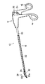
今図面をより詳細に参照すると、同じ参照番号は、類似或いは同一の部品を示し、図1は、内視鏡検査向き外科式用具10の実施例を示す。その最も簡単な形態において、器具は、固定ハンドル14及び回転ハンドル16からなるハンドル組立体12を有する。外側管状部材20を有する本体部分18が、ハンドル組立体から延び、摺動可能な内側ロッド部材22がこの外側管状部材20を同軸関係をなして貫通する。外側管20は、固定ハンドル14に固定され、内側ロッド22は、回転可能連結部26で回転ハンドル16に固定される。ハンドル16は、枢着部24を中心に回動して、固定ハンドル14に対して移動する。
【0024】
器具機構28が、本体部分18の遠位端に取り付けられ、下側ジョー部材30A及び上側ジョー部材30Bからなる。器具機構は、枢着部32で本体部分18に連結され、リンク機構34を介して枢着部32を中心に往復運動を行う。リンク機構34は、以下でより詳細に説明する。
使用中、回転ハンドル16は固定ハンドル14に対して枢着部24を中心に回転し、内側ロッド22は、連結部26での押し引き力13に応答して外側管20内で往復摺動する。連結部26の機能は、以下でより詳細に説明する。
【0025】
ロッド22が管20内を摺動するとき、リンク機構34が作動して枢着部32を中心にジョー部材30A及び30Bを回転させ、これらを開閉する。ジョー部材30A及び30Bははさみ、解剖用ジョー又は掴み機構若しくは特定の外科手術に必要とされる他の任意の用具からなるのがよい。
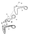
図2から最も良くわかるように、回転ハンドル16は一対の止め部材36A及び36Bを有し、各々ボス部材38A及び38Bと協働して回転ハンドル16の枢着部24を中心とした回転運動を制限する。止め部材は、回転ハンドル16が固定ハンドル14から離れるとき、近位の止め部材36Aがボス38Aに接触して、ハンドル16の実際の回転を制限するように枢着部24の反対側に位置決めされる。ハンドル16がハンドル14の方に移動するとき、遠位止め部材36Bはボス38Bに接触してその方向にハンドル16が回転するのを制限する。止め部材は外科用用具の開閉中、器具機構に過度の力が作用するのを防止するために設けられる。この方法により、器具機構の損傷或いは破壊の可能性を、非常に減じ、或いは除去する。
【0026】
今図3を参照すると、図3は、本発明の内視鏡検査用外科器具の第1の変形実施例10Aを示す。器具10Aは、外科手術中に患部組織を焼灼する電気メスの連結を除いて、器具10と同様である。固定ハンドル14は、必要な電流を器具に供給する電気ジャック部材(図示せず)を受け入れるための接続ポート42を有する。板バネ44が、患部の器具機構に電流を供給する外側管部材20とポート42とを電気的に接続する。板バネはポート42に接続部材46を又、外側管に接続部材48を有する。接続部材は、本質的に板バネを構成する材料の弾性に依存するが、もちろん従来の電気的接続でもよい。
【0027】
外側管に電気が付与されると、電気が外側管に沿って器具機構まで伝わり、この例でははさみ装置50或いは焼灼フック、ピンセット等の他の器具機構であるのが好ましい。この装置を使用する外科医を電気ショックから守るために、ハンドルは、装置の重量を軽くし、かつ電気的に絶縁する剛性なプラスチック材料で作られることが好ましい。
【0028】
使用中、電気的ショックを防止するために、絶縁部材40が外側管20に設けられ、絶縁部材は熱収縮管からなるのが好ましい。熱収縮管40は固定ハンドル14の中を通り電気的ショックの可能性を防止する。
接続ポート42は、フィンガーグリップで固定ハンドル14に取り付けられているものとして図示されているが、図5に関連して図示し、以下で説明するように、接続ポートをハンドルの頂部に位置決めすることも意図する。
本発明における接続ポートの位置決めは、外科医に器具機構28の患部を観察するために本体部材18の妨害のない視線を提供する。
【0029】
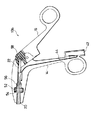
図4は、本発明の好ましい実施例を示し、この例では器具10Bは電気メス装置の特徴を備えるとともに、回転可能な本体部分18用の装置を有する。図4からわかるように、スロット54が、固定ハンドル部材14内に設けられ、ハンドル部材を完全に貫通する。ブッシュ部材56を介して外側管20に固定された回転可能なノブ52がスロット54内に配置される。回転可能なノブ52及びブッシュ部材56は、以下でより詳細に説明する。
【0030】
又図4で最もよくわかるように、内側ロッド部材22は、回転可能なブッシュ58を介して回転ハンドル16に連結されている。ブッシュ58は、回転ハンドル16の回転中、回転するから、ロッド部材22を管20内で往復動させると、ブッシュ部材58はロッド22の半径方向の動きを最小にし、或いは除去して、ロッド22が長手方向にのみ移動することを保証する。これは、ロッド部材22に加わる過度のトルク力を軽減するとともに、連結部26における不要な過度の力を軽減して、ハンドル或いは内側ロッド部材22の損傷を防止する。この回転可能なブッシュ部材58によって提供されるもう1つの特徴は、ロッド部材22の半径方向の動きを大きく減じ或いは除去することにより、外側管20と内側ロッド部材22との間の正確な許容差を維持できるので必要なスペースを減じ、従来の外科器具より小さな大きさで作れることである。さらに、半径方向の撓みを大幅に減じ、或いは除去することにより、器具の精度は非常に増大する。回転可能なブッシュ部材58の特徴は以下でより詳細に説明する。
【0031】
今図5を参照すると、固定ハンドル14A及び回転ハンドル16Aが、係止機構64A及び64Bを有するものとして示されている。図5は、ハンドル部材14Aの側面破断図を示し、本発明に好ましい実施例である。この図から明確に理解できるように、ハンドル部材14A及びハンドル部材16Aは枢着部24で連結され、ハンドル組立体の開閉中、近位の止め部材36Aがボス38Aに接触して固定ハンドル14Aからの回転ハンドル16Aの回転を制限する。ハンドルを互いの向きに移動させるとき、止め部材36Bがボス部材38Bに接触してその方向の回転を制限する。係止機構64A及び64Bは、開閉動作中種々の位置にハンドルを位置決めするのに利用され、もちろん器具の遠位端で器具機構に種々の閉鎖力を作用させることができる。
【0032】
ハンドル14Aは回転可能なノブ52を受け入れるスロット54を有する。さらに、多角形形状のボス構造体57が器具が組み立てられたときブッシュ部材56の対応する多角形形状を受け入れるハンドル内に設けられる。構造体57とブッシュ56は協働して本体部分18の回転量を増加させ、結果として器具機構28を回転経路に沿った種々の位置に位置決めすることができる。ボス構造体57によって示される面の数は、ブッシュ56の多角形横断面の面の数に等しい。各構造体は、12面であるのが好ましい。
【0033】
さらに図5は、電気ポート60の好ましい位置を示し、ハンドル部材14Aの頂部で、本体部分18により形成された器具の長手軸線方向に対してある角度に位置決めされる。ポート60は、長手軸線方向に対して30°以下の角度に位置決めされるのが好ましく、その最適な位置で、長手軸線方向に対して9°に位置決めされる。これにより、外科医は、器具の長手軸線方向に明確な視線を得て患部での動作を観察することができる。ポート60は穴61から電気ジャック部材を受け入れ、電気接続が、63からわかるようにジャック(図示せず)を外側管部材と接続するトラック62で保持された板バネ部材を介してなされる。
【0034】
図6及び図7は、例えばはさみ刃72及び74を有するはさみ機構からなる器具機構を示す。この実施例において、ハウジング部材66は、外側管20に取り付けられ、器具機構はハウジング部材66に取り付けられている。ハウジング部材66は、図17及び図18に詳細に示されており、枢着ピン68を受け入れる半径方向の穴がハウジング部材に設けられ、開閉中、器具機構をピン68を中心に回転させることができる。ハウジング部材66は長手方向の穴70を有し、図17及び図18に最もよく示されるように器具機構を構成するジョー部材を開閉させることができる。
【0035】
又図6に示されるように、補剛部材75がはさみ刃72及び74に設けられ、刃を補強して刃の強さを増す。補剛部材75は、刃72及び74を、特に遠位端77で非常に薄く形成することを可能にする。補剛部材75は、戻り止め或いは外方打ち抜き領域を構成し、刃72及び74の補強部は刃を互いの向きに付勢して、刃の剪断機能を高める。ステンレス鋼、チタン等の金属であるのが好ましい刃の材料の弾性は、刃を薄く作るほど減じる傾向にあり、補剛部材75は、刃72及び74を互いの向きに動かして、切断動作の効率を維持する。補剛部材75は、接着材、はんだ付け等により刃に固定された材料の組み立て領域或いは材料の層からなる。
【0036】
図7からもっとも良くわかるように、はさみ刃72及び74は開位置で示され、ハンドル部材(図示せず)が開位置にあり、即ち回転ハンドル16は固定ハンドル14から遠ざけられる。
ハンドルが動くと、内側ロッド部材22はジョー機構28に向かって外側管20を通って摺動する。図7からわかるように、はさみ刃72及び74は、カムスロット76及び78を有し、スロットは内側ロッド22に取り付けられたベアリングポスト80を受け入れる。ロッド22が動くと、ベアリングポスト80はカムスロット76及び78内で摺動し、固定枢着部68を中心に刃72及び74を回転させ、刃を開閉させる。刃が開くとき、刃の尾端部はハウジング部材66のスロット70を貫通して、刃を開く。
【0037】
ハンドル部材14及び16が互いの向きに引かれるとき、内側ロッド22はジョー機構から遠ざかるように、ハンドル組立体に向かってベアリングポスト80を引く。これが起こると、ベアリングポスト80がカムスロット76及び78内で摺動して、刃を閉じる。
図8を参照すると、図8は、器具機構28からなる解剖器具の分解斜視図を示す。この実施例において、外側管20は、解剖部材の開閉を行うスロット21を有する。この実施例において、ハウジング部材66は除去されている。
【0038】
解剖部材82及び84は、図7に示す装置と同様のカムスロット装置を有する。カムスロット86は上部解剖部材82に設けられ、カムスロット88は下部解剖部材84に設けられる。この実施例において、内側ロッド22は外側管20に配置され、解剖部材82及び84は管20の穴69を貫通する枢着ピン68によって外側管20に回動自在に取り付けられる。ロッド22は、ベアリングポスト部材90によってカムスロット装置に固定される。ロッド部材22が管20内で前方に摺動すると、図11から最も良くわかるように、ベアリングポスト90はカムスロット86及び88内で摺動して、枢着部68を中心に解剖部材を回転させ、部材を開き、ロッド部材22が解剖機構から遠ざかるように摺動するとき、ポスト90はカムスロット86及び88内で摺動して、解剖機構から遠ざかり、解剖部材82及び84を閉位置に引く。
【0039】
又図11からわかるように、ジョーが閉じると、枢着部に最も近い端部が互いに接触する前にジョー部材82及び84の遠位端は互いに接触する。6°以下好ましくは2°の角度がこの時点で維持され、であるが、ジョーに圧力を徐々に加える。
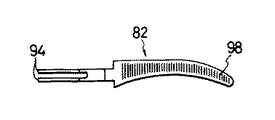
図9及び図10は、解剖装置の好ましい実施例を示し、本体部分は組織を掴んでちぎるのを容易にする、三か月形の形状を有する。解剖部材の表面は、外科手術中組織を解剖したり、ちぎるために設けられたセレーション98を有する。
カムスロット86及び88に形成された複突出部94及び96は、解剖機構が互いに妨害しあうことなく開閉するのを可能にする。突出部94の間のスペースは、突出部96の間のスペースより小さく、突出部94は突出部96内に嵌まる。スロット21が、外側管20に設けられ、解剖装置を開閉させるために、突出部を管20の外周に通す。
【0040】
図12から図16は、本発明の内視鏡用外科器具の器具機構として使用できる掴み機構を示す。図12及び図13は、組織を掴んで保持するのを容易にするセレーション104を備えた一対の掴み部材100及び102を示す。図12及び図13に示す実施例において、本体部分100及び102は、突出部106の廻りに一体に成形されたプラスチック材料からできているのが好ましい。図14から最も良くわかるように、ポスト部材110が設けられ、この廻りに、部材100及び102が成形される。突出部106は、カムスロット108及び枢着穴109を有し、掴み機構は、はさみ機構及び解剖機構と関連して上述した方法と同様の方法で作動する。
【0041】
図15及び図16は、ステンレス鋼、チタン、アルミニウム等の金属で作られている部分を除いて、図12から図14の掴み機構を示す。突出部112及び114は解剖装置について上述して方法と同様の方法で協働して、突出部112は突出部114間の距離よりも大きく間隔を隔てられ、突出部114は掴み機構の開閉中突出部112間を動く。
【0042】
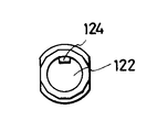
今図19及び図21を参照すると、回転可能な本体部分と一緒に本体部分及び器具機構を回転させるのに用いられる回転ノブ52及びブッシュ部材56を示す。回転ノブ52は、外科医の親指その他の指で容易に操作できるようにローレットを切り或いはうね116を備えるのが好ましい。回転ノブ52は、ブッシュ部材56がその中を貫通できるように、中空で通路118を有するのが好ましい。図21は、回転可能なブッシュの面125と協働する一連の面126を有する多角形横断面のブッシュ部材を示す。ブッシュは回転ノブ52(図4参照)から外方に延び、面126は、ボス構造57(図5参照)と協働して本体部分18の回転量を増加させ、回転軸線に沿って種々の位置に器具機構を位置決めする。図22は、ブッシュを外側管20に結合して固定させるボス部材124を最もよく示す。ボス124は管20の溝或いはスロットの中に嵌まり、ブッシュ及び回転ノブを外側管20に固定させる。ブッシュ56及び回転ノブ52は又単一集合ユニットとして作られてもよい。ノブ52及びブッシュ56はプラスチックで作られるのが好ましく、電気メスの特徴部の使用中絶縁体が設けられる。
【0043】
固定ハンドルに回転ノブを位置決めすることにより、外科医は内視鏡用外科器具10Bを片手で操作できるので、外科医は装置を持っているとき、自由な他方の手で外科治療をしながら親指でノブを回すことができる。
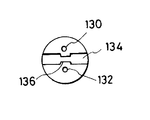
ノブを回すと、外側管が回転し、続いて枢着部68を回転させ、その結果、器具機構を回転させる。器具機構の回転により、枢着ブッシュ58内で生じる内側ロッド22の回転を引き起こす。枢着ブッシュ58は図23及び図24に最も良く示されており、ディスクは、各々、一対のディスク128を有し、ディスクを互いに係合させるためにポスト部材130とディスクに形成された穴132とを有する。溝134は、切欠き部分136を備え、該切欠き部分は、対応する切欠きが形成されているロッド部材22の端部を受け入れる。この切欠きは、ロッド22は確実に所定の長手方向に移動でき、同時に回転移動もできる。上述したように、ハンドル部材16が回転すると、ブッシュ58は回転して管内のロッド部材の半径方向の撓みを大幅に減じ或いは除去する。これは、ロッドに作用するトルク力を軽減し、長期使用後の装置の損傷を最小限に抑える。
【0044】
図25及び図26は、本発明による器具機構のさらなる実施例を示す。
固定はさみ刃140が、固定横枢着ピン144を就寝に移動可能なはさみ刃142に取り付けられている。この横ピン144は上述(図17及び図18参照)したような半径方向穴67によってハウジング部材66に取り付けられている。このはさみの実施例は、組織を切り離すために刃140及び142の剪断動作を利用する。アーチ状の切断面146及び148は各々刃140及び142の遠位端の対向する鉛直面に形成され、剪断切断動作をより容易にしている。特に有利な実施例においては、バネワッシャー150(図27参照)を設けて、移動刃142を固定刃140に押しつける。刃140及び142が互いに剪断するとき、押しつけ力はより良好な切断作用を与える。
【0045】
横ベアリングポスト152が、内側管22に取り付けられ、内側管20内で長手方向の往復運動ができるようになっている。長手方向スロット154が横着軸ピン144に近い領域でかつ横枢着ピン144と長手方向に整列して、固定刃140の近位端内に設けられる。ベアリングポスト152は、スロット154と嵌り合って、その中を長手方向動作に運動でき、枢着ピン144を中心とする刃140の回転動作を防止するのに役立つ。
アーチ状カムスロット156が、横着軸ピン144に近い領域で可動刃142の近位端に設けられる。ベアリングポスト152は、アーチ状カムスロット156と嵌り合い、外側管20に対する内側管22の長手方向の動作を枢着ピン144を中心とする刃142の回転動作に変える。したがって、図25及び図26に示す実施例において、横ベアリングポスト152が近位から遠位に移動するとき、刃142はロッド22と長手方向同一平面内に位置したままで、刃140に対して開いた状態にカムされている。それと関連して、ロッド22の近位動作により、図26に示すように、ベアリングポスト152は刃142を閉位置までカムさせる。
【0046】
この実施例は剪断はさみ機構に向けられているが、例えば掴み具、解剖器具、クランプ等の他の器具も意図されている。
本発明の内視鏡用外科器具は、コンパクトで重量が軽く、しかも内視鏡による外科治療中外科医が片手で装置を操作し、かくしてもう片方の手を治療中他の目的のために解放させるのに必要とされる沢山の特徴を取り込んだ器具が簡単に使用できる。本器具は、従来の技術が直面していたたくさんの欠点に打ち勝ち、取り扱いが容易で、しかも構造が簡単な精密器具を提供する。本発明は好ましい実施例に関して特に示し、説明してきたが、形態及び細部における種々の変形が、本発明の範囲及び意図を逸脱することなく行われうることが当業者に理解されるであろう。さらに、上述したこれらの提言等の変形は、それらに限定されることなく本発明の範囲内で考えられうる。
【図面の簡単な説明】
【図1】本発明による内視鏡検査向外科用器具の部分破断透視図である。
【図2】本発明による内視鏡検査向外科用器具のハンドルの分解透視図である。
【図3】本発明による内視鏡検査向外科用器具の変形実施例の側面破断図である。
【図4】本発明による内視鏡検査向外科用器具の2番目の変形実施例の側面破断図である。
【図5】本発明による内視鏡検査向外科用器具の好ましい実施例の側面破断図である。
【図6】本発明による内視鏡検査向外科用器具の仕組みの上部破断図である。
【図7】本発明による内視鏡検査向外科用器具の図6の仕組みの側面破断図である。
【図8】本発明による内視鏡検査向外科用器具の別の仕組みの分解透視図である。
【図9】本発明による内視鏡検査向外科用器具とともに使用するための解剖器具の上部部材の平面図である。
【図10】本発明による内視鏡検査向外科用器具とともに使用するための解剖器具の下部部材の平面図である。
【図11】本発明による内視鏡検査向外科用器具に取り付けられた図9及び図10の解剖器具の側面部分破断図である。
【図12】プラスチック成形掴み機構の上部部材の平面図である。
【図13】プラスチック成形掴み機構の下部部材の平面図である。
【図14】掴み機構の部材の側面図である。
【図15】金属製上部掴み部材の平面図である。
【図16】金属製掴み機構の下部部材の平面図である。
【図17】本発明による内視鏡検査向外科用器具のハウジング部材の側面図である。
【図18】本発明による内視鏡検査向外科用器具のハウジング部材の図17の線A−Aからみた上部破断図である。
【図19】本発明による内視鏡検査向外科用器具の使用のための回転ノブの部分側面破断図である。
【図20】図19の回転ノブの正面図である。
【図21】本発明による内視鏡検査向外科用器具の使用のためのブッシュ部材の部分側面破断図である。
【図22】図21のブッシュの正面図である。
【図23】本発明による内視鏡検査向外科用器具の使用のための枢着ブッシュの側面図でる。
【図24】図23の枢着ブッシュの正面図である。
【図25】1つのジョー部材だけが回転する本発明によるはさみ機構の開状態の側面図である。
【図26】閉状態の図25のはさみ機構の側面図である。
【図27】図25及び図26のはさみの固定枢着ピンの断面平面図である。
【符号の説明】
10 内視鏡検査向外科用器具
12 ハンドル組立体
14 固定ハンドル
16 回転ハンドル
18 本体部分
20 外側管
22 内側ロッド
24 枢着部
26 連結部
28 器具機構
30 ジョー機構
32 枢着部
34 リンク機構
36 止め部材
38 ボス
40 絶縁部材
42 接続ポート
44 板バネ
52 ノブ
54 スロット
56 ブッシュ部材
72 はさみ刃[0001]
[Industrial application fields]
The present invention relates to a surgical instrument for endoscopy, and more particularly to a surgical instrument having a reciprocating jaw member that rotates in response to opening and closing of the handle member that causes the handle movement to open and close the jaw mechanism through the elongated tubular body member. .
The present invention further provides such an apparatus wherein the jaw mechanism comprises a cutting scissor blade, a gripping device for holding tissue during surgery, a gripping device for holding a surgical needle, and the like. The device of the present invention comprises a rotatable tubular body for selectively positioning the angle at which the jaw mechanism operates, and is also ready to use an electric scalpel ability to cauterize the affected area.
[0002]
[Problems to be Solved by the Invention and Means for Solving]
The prior art discloses various endoscopic surgical instruments that utilize a generally complex device that opens and closes the handle and jaw members to facilitate operation of the device at the affected area. Many devices provide a complex structure in which the linkage mechanism that opens and closes the jaws requires a large number of moving parts, while two sliding devices that actuate the linkage mechanism in response to movement of the handle member are provided. Provided between the extension rod members. Further, in many cases, rotation of the handle member exerts an unnecessary radial torque force on the rod, and it is necessary to provide more space on the handle member in order to adapt to the radial movement of the rod.
[0003]
Currently used endoscopy instruments include multiple devices having interchangeable shaft assemblies and jaw mechanisms, with a common handle used with a series of instruments. However, these devices have the disadvantage that the coupling mechanism often obstructs the surgeon's line of sight and loosens the coupling, reducing the integrity of the device. These drawbacks are fatal in that surgical endoscopy requires a precise instrument that carefully monitors tolerances. As the connection wears, accuracy is sacrificed and the utility of the instrument is reduced.
[0004]
Greenberg, U.S. Pat. No. 4,674,501 discloses a surgical instrument having a pair of reciprocating axes with a rotating index knob that rotates the axis to position the cutting instrument at a specific angle relative to the handle. The shafts slide on top of each other in response to opening and closing of the handle member to open and close the jaw members of the cutting instrument. The housing is secured to the fixed handle so that the shaft assembly rotates with the index knob. One shaft is a ball and socket joint, which is fixed to the moving handle, and this ball and socket joint facilitates sliding of the movable shaft on the fixed shaft. The handle assembly is detached from the housing with a screw and the ball joint slides out of the socket to remove the handle. In this type of device, the fact that the ball and socket joints are inherently loose couplings that deteriorate during continuous use, at the same time, increases the integrity of the device due to the number of moving parts. It is easy to produce the above-mentioned fault.
[0005]
U.S. Pat. No. 4,915,152 to Greenberg discloses a clipping device having a fixed handle and a rotating handle with an elongated shaft attached thereto. A pair of reciprocating jaw members that operate in response to the rotational movement of the handle are provided at the end of the shaft. An inner shaft member is attached to the rotating handle, and the shaft member passes through an outer tube member fixed to the fixed handle. Since the rod member penetrates the fixed handle and penetrates the outer tube at a position fixed to the fixed handle, the rod is attached to the fixed handle in a non-movable position, so that the rod moves in the outer tube in the radial direction. It must be the cause. In this connection, a bushing member is required on the inside of the fixed handle to absorb the radial play of the rod member during opening and closing of the handle.
[0006]
Straub et al., U.S. Pat. No. 4,590,936, discloses a microsurgical instrument having a complex gear mechanism that translates handle movement into jaw member opening and closing movements. A helical slot is provided in the shaft member and moves the pin through the slot to move the jaw member. Further, a ball and socket joint for connecting the movable handle to the inner rod are provided in the movable handle.
[0007]
U.S. Pat. No. 4,1280,992 to Bauer et al. Discloses a tweezer with a cautery accessory that conducts current to an jaw member by an outer tube. A complex insulating device is provided to insulate the shaft itself and to insulate the handle from the shaft. This device has the disadvantage that in order to insulate the handle, the rod member is fixed to the insulating bush and a second rod connected to the handle member is provided on the bush. Furthermore, the connection point of the electrical connection is arranged at a position that obstructs the surgeon's line of sight when the surgeon looks down on the affected device.
[0008]
The novel endoscopic surgical instrument according to the present invention eliminates the disadvantages encountered in the prior art and is easy to manufacture and efficient to use, eliminating many moving parts required by prior art devices Provide precise instruments that can be used. The instrument of the present invention has a number of features used by surgeons during surgery, while maintaining light weight, being easy to handle and allowing all features to be operated with one hand. Furthermore, the features are positioned to provide maximum visibility for the surgeon without disturbing the line of sight to the affected area.
[0009]
The present invention provides a novel endoscopic surgical instrument incorporating all the features necessary for endoscopic surgical treatment, and provides a lightweight, easy-to-handle device that can be operated with one hand. The device is simple to assemble and can comprise any of a series of jaw members for various surgical treatments. The device is a high precision instrument that eliminates many moving parts normally associated with such a device, thus reducing the case of mechanical failure or ultimate failure of the instrument that requires costly repairs. is there.
[0010]
The endoscopic surgical instrument of the present invention consists essentially of a handle assembly, an elongated body assembly, and an instrument mechanism attached to the distal end of the body assembly remote from the handle assembly. The handle assembly has a fixed handle and a rotating handle, and the body assembly is attached to and extends from the fixed handle assembly. The body assembly comprises an outer tube member and an inner rod member that extends coaxially within the outer tube member. The rod member is attached to the rotating handle and the tube member is fixed to the fixed handle in a conventional manner. The outer tube is preferably provided with a detent that cooperates with the boss inside the fixed handle to lock the outer tube in place. As the rotary handle moves, the rod member slides back and forth within the outer tube member.
[0011]
An instrument mechanism that opens and closes in response to the movement of the rotating handle relative to the fixed handle is attached to the distal end of the main assembly. The instrument mechanism is composed of a pair of jaw members, and one or both of the jaw members open and close to perform various endoscopic surgical treatments. The jaw member includes, but is not limited to, a scissor device, a dissecting device, a gripping device, and the like.
[0012]
In one embodiment, the jaw mechanism is secured to the outer tube member by a lateral post member that serves as a common pivot point for both of the jaw members to rotate. Each jaw member comprises a cam slot having a cam portion extending from a pivot point and extending from the pivot point into the outer tube. The upper jaw member has a pair of spaced apart protrusions, each protrusion having a cam slot that overlaps one another in the lateral direction. The lower jaw member also has a pair of extensions spaced less than the spacing between the protrusions of the upper jaw member, the lower protrusion passing between the upper protrusions. The lower protrusion also has a transverse double slot positioned at an angle with respect to the upper cam slot. The jaw mechanism is secured to the outer rod by a common pivot point.
[0013]
The inner rod member typically includes a bearing surface comprising a post member that passes through and engages the cam slots of both jaw members. As the rotating handle moves, the rod slides through the outer tube, causing the post members to rotate about a common pivot point and opening the jaw members. Since the cam slots are at an angle to each other, when the post rests in the slot, movement of the post member within the slot causes both jaw members to rotate. When the rod reciprocates, the jaw mechanism opens and closes.
[0014]
In order to prevent excessive force from acting on the jaw member, the rotary handle includes a pair of stop members that secure the rotary handle to the fixed handle and are positioned near the pivot point of movement of the rotary handle. Is done. The upper or proximal stop member abuts the boss of the fixed handle and prevents the jaw mechanism from opening too much, while the distal or lower stop member abuts the fixed handle and closes the jaw while it is closed. Prevent excessive force from acting on the mechanism. Further, the force action on the jaw mechanism can be adjusted during design and manufacture by the mutual engagement of the stop member of the rotating handle and the boss of the fixed handle.
[0015]
A novel feature of the present invention is that a second pivot point is provided on the rotary handle to which the inner rod member is attached. As the handle rotates, the second pivot point rotates, causing the inner rod to move longitudinally within the outer tube, minimizing radial deflection. This is an important feature of the present invention, which reduces the radial wear of the inner rod and prevents weakening of the structure during prolonged use. Furthermore, the required internal spacing between the outer tube and the inner rod can be reduced, resulting in a more compact and streamlined instrument. Furthermore, unwanted torque forces are removed at the pivot point, thus minimizing the possibility of mechanical failure at the connection between the rotating handle and the movable inner rod.
[0016]
The invention also features a connection port for providing an electrical knife capability to the device. In this embodiment of the invention, the connection port is preferably provided on a fixed handle on the longitudinal axis side opposite the finger grip portion. The connection port is positioned at an angle with respect to the longitudinal axis, which is preferably no more than 30 °, and in a preferred embodiment is 9 ° with respect to the longitudinal axis, and from the body assembly Extend in the direction. In this way, the surgeon's line of sight can clearly see the affected area without being disturbed. The connection port allows a connection with a suitable jaw member to be inserted into the device. The electrical connection between the port and the outer tube is made by a leaf spring extending from the port region to the outer tube. The outer tube is preferably a heat shrink tube that is electrically insulated and extends to a substantial portion of the length of the outer tube. In this embodiment, the handle is molded from a plastic material to provide electrical insulation to the user.
[0017]
An electrical connection port is also provided adjacent to the finger grip of the fixed handle so that the jaw members extend downward from the device so as not to obstruct the surgeon's line of sight. In this case, the leaf spring member extends from the port through the fixed handle to the outer tube, completing the electrical connection.
A further feature of the present invention is that the outer tube member is provided with a rotatable knob that rotates the body assembly and the jaw mechanism to position the jaw at a desired angle relative to the longitudinal axis during the surgical procedure. The rotatable knob is secured to the outer tube and positioned in a slot that passes through the stationary handle, so that the surgeon rotates the knob with the thumb while holding the stationary handle with the finger, resulting in a body assembly And the jaw members can be rotated. This frees the surgeon's one hand and allows other instruments to be operated simultaneously during treatment.
[0018]
The rotatable knob is fixed to the bush, and the bush is fixed to the outer tube member. The bush has a polygonal cross section that matches the boss member inside the fixed handle. This increases the amount of rotation of the body assembly and jaw mechanism to a desired angle with respect to the longitudinal axis direction. The bushing preferably has a dodecahedron cross section.
In a preferred embodiment, all the features described above are incorporated into a single endoscopic surgical instrument, the instrument having an electrically rotatable scalpel. However, the instrument may be configured without one or more of the features while providing a light weight and high precision instrument.
[0019]
Therefore, it is an object of the present invention to provide a surgical instrument for endoscopy that allows a surgeon to manipulate all features with one hand.
Another object of the present invention is to provide a lightweight endoscopic surgical instrument that provides a clear line of sight to the surgeon during the surgical procedure.
It is a further object of the present invention to provide an endoscopic surgical instrument that prevents instrument damage by preventing excessive force from acting on the actuating instrument mechanism regardless of whether the instrument mechanism is opened or closed.
[0020]
A still further object of the present invention is that the tolerance between the slidable inner rod member that operates the jaws and the outer tube member that retains the jaw mechanism is such that the radial direction of the rod during longitudinal movement in the tube. It is an object to provide a surgical instrument for endoscopy that has little or no deflection.
Still another object of the present invention is to provide a handle assembly provided with a first pivot point for rotating a movable handle around a fixed handle and a second pivot point for connecting a movable rod member to the rotary handle. And providing a surgical instrument for endoscopy that allows rotation of a second pivot point to prevent radial deflection of the rod during longitudinal movement.
[0021]
Yet another object of the present invention is to provide an endoscopic surgical instrument having an electric scalpel capability in which the connection port of the electrical jack member is outside the surgeon's line of sight during operation.
A still further object of the present invention is to provide an endoscopic surgical instrument having a rotatable body member and a jaw mechanism that can rotate even when the surgeon's hand is blocked.
[0022]
Yet another object of the present invention is to couple the inner rod to the rotating handle to prevent radial deflection of the rod during longitudinal movement, with a rotatable body assembly, jaw mechanism, electrical knife capability, and longitudinal movement. A surgical instrument for endoscopy having all the above features, including a rotatable pivot point.
The foregoing objects and other features of the present invention will be readily apparent and understood by referring to the following detailed description of an embodiment of a surgical instrument for endoscopy in conjunction with the accompanying drawings.
[0023]
【Example】
Referring now more particularly to the drawings, like reference numerals indicate like or identical parts, and FIG. 1 illustrates an embodiment of a
[0024]
An
In use, the
[0025]
When the
As best seen in FIG. 2, the
[0026]
Referring now to FIG. 3, FIG. 3 shows a first modified embodiment 10A of the endoscopic surgical instrument of the present invention. Instrument 10A is similar to
[0027]
When electricity is applied to the outer tube, the electricity is transmitted along the outer tube to the instrument mechanism, which in this example is preferably a
[0028]
In use, in order to prevent electrical shock, an insulating
Although the
The positioning of the connection port in the present invention provides the surgeon with an unobstructed line of sight of the
[0029]
FIG. 4 shows a preferred embodiment of the present invention, in which the instrument 10B has the features of an electric scalpel device and has a device for a
[0030]
As best seen in FIG. 4, the
[0031]
Referring now to FIG. 5, the fixed handle 14A and the rotating handle 16A are shown as having locking mechanisms 64A and 64B. FIG. 5 shows a side cutaway view of the handle member 14A, which is a preferred embodiment of the present invention. As can be clearly seen from this figure, the handle member 14A and the handle member 16A are connected by a
[0032]
The handle 14A has a
[0033]
Further, FIG. 5 shows a preferred position of the
[0034]
6 and 7 show an instrument mechanism comprising a scissor mechanism with
[0035]
Also, as shown in FIG. 6, a stiffening
[0036]
As best seen in FIG. 7, the
As the handle moves, the
[0037]
When the
Referring to FIG. 8, FIG. 8 shows an exploded perspective view of the dissecting instrument comprising the
[0038]
[0039]
As can also be seen from FIG. 11, when the jaws are closed, the distal ends of the
9 and 10 show a preferred embodiment of the dissecting device, wherein the body portion has a three-month shape that facilitates grasping and tearing tissue. The surface of the dissection member has
[0040]
12 to 16 show a gripping mechanism that can be used as the instrument mechanism of the endoscopic surgical instrument of the present invention. 12 and 13 illustrate a pair of gripping
[0041]
FIGS. 15 and 16 show the gripping mechanism of FIGS. 12 to 14 except for portions made of metal such as stainless steel, titanium, and aluminum. The
[0042]
Referring now to FIGS. 19 and 21, there is shown a
[0043]
Positioning the rotary knob on the fixed handle allows the surgeon to operate the endoscopic surgical instrument 10B with one hand, so that when the surgeon holds the device, the thumb knob while performing surgical treatment with the other free hand Can be turned.
Turning the knob causes the outer tube to rotate, which in turn causes the
[0044]
25 and 26 show a further embodiment of the instrument mechanism according to the invention.
A fixed
[0045]
A
An
[0046]
Although this embodiment is directed to a shear scissor mechanism, other instruments such as grips, dissection instruments, clamps, and the like are also contemplated.
The endoscopic surgical instrument of the present invention is compact, light weight and allows the surgeon to operate the device with one hand during endoscopic surgery, thus freeing the other hand for other purposes during treatment It is easy to use instruments that incorporate many of the features that are needed. The instrument overcomes many of the disadvantages faced by the prior art and provides a precision instrument that is easy to handle and simple in construction. While the invention has been particularly shown and described with reference to preferred embodiments, those skilled in the art will recognize that various modifications in form and detail may be made without departing from the scope and spirit of the invention. Furthermore, modifications such as these proposals described above can be considered within the scope of the present invention without being limited thereto.
[Brief description of the drawings]
FIG. 1 is a partially broken perspective view of a surgical instrument for endoscopy according to the present invention.
FIG. 2 is an exploded perspective view of a handle of a surgical instrument for endoscopy according to the present invention.
FIG. 3 is a side cutaway view of a modified embodiment of a surgical instrument for endoscopy according to the present invention.
FIG. 4 is a side cutaway view of a second alternative embodiment of an endoscopic surgical instrument according to the present invention.
FIG. 5 is a side cutaway view of a preferred embodiment of a surgical instrument for endoscopy according to the present invention.
FIG. 6 is a top cutaway view of the mechanism of a surgical instrument for endoscopy according to the present invention.
7 is a side cutaway view of the mechanism of FIG. 6 of an endoscopic surgical instrument according to the present invention.
FIG. 8 is an exploded perspective view of another mechanism of a surgical instrument for endoscopy according to the present invention.
FIG. 9 is a plan view of an upper member of a dissecting instrument for use with an endoscopic surgical instrument according to the present invention.
FIG. 10 is a plan view of a lower member of a dissecting instrument for use with an endoscopic surgical instrument according to the present invention.
11 is a partial cutaway side view of the dissecting instrument of FIGS. 9 and 10 attached to an endoscopic surgical instrument according to the present invention. FIG.
FIG. 12 is a plan view of the upper member of the plastic molding gripping mechanism.
FIG. 13 is a plan view of a lower member of the plastic molding gripping mechanism.
FIG. 14 is a side view of a member of a gripping mechanism.
FIG. 15 is a plan view of a metal upper gripping member.
FIG. 16 is a plan view of a lower member of the metal gripping mechanism.
FIG. 17 is a side view of a housing member of an endoscopic surgical instrument according to the present invention.
18 is a top cutaway view of the housing member of the surgical instrument for endoscopy according to the present invention taken along line AA in FIG.
FIG. 19 is a partial side cutaway view of a rotary knob for use with an endoscopic surgical instrument according to the present invention.
20 is a front view of the rotary knob of FIG. 19;
FIG. 21 is a partial side cutaway view of a bushing member for use with a surgical instrument for endoscopy according to the present invention.
22 is a front view of the bush of FIG. 21. FIG.
FIG. 23 is a side view of a pivot bushing for use with an endoscopic surgical instrument according to the present invention.
24 is a front view of the pivot bushing of FIG. 23. FIG.
FIG. 25 is a side view of an open state of a scissor mechanism according to the present invention in which only one jaw member rotates.
26 is a side view of the scissor mechanism of FIG. 25 in a closed state.
27 is a cross-sectional plan view of the fixed pivot pin of the scissors of FIGS. 25 and 26. FIG.
[Explanation of symbols]
10 Surgical instruments for endoscopy
12 Handle assembly
14 Fixed handle
16 Rotating handle
18 Body part
20 Outer tube
22 Inner rod
24 pivoting part
26 Connecting part
28 Instrument mechanism
30 jaw mechanism
32 pivot attachment
34 Link mechanism
36 Stopping member
38 Boss
40 Insulating material
42 Connection port
44 leaf spring
52 knob
54 slots
56 Bushing member
72 Scissor blade
Claims (7)
Applications Claiming Priority (2)
| Application Number | Priority Date | Filing Date | Title |
|---|---|---|---|
| US59367090A | 1990-10-05 | 1990-10-05 | |
| US07/593670 | 1990-10-05 |
Publications (2)
| Publication Number | Publication Date |
|---|---|
| JPH04246344A JPH04246344A (en) | 1992-09-02 |
| JP3676385B2 true JP3676385B2 (en) | 2005-07-27 |
Family
ID=24375656
Family Applications (1)
| Application Number | Title | Priority Date | Filing Date |
|---|---|---|---|
| JP25811291A Expired - Lifetime JP3676385B2 (en) | 1990-10-05 | 1991-10-04 | Surgical instrument for endoscopy |
Country Status (5)
| Country | Link |
|---|---|
| US (1) | US5522830A (en) |
| EP (1) | EP0484671B1 (en) |
| JP (1) | JP3676385B2 (en) |
| CA (1) | CA2050868C (en) |
| DE (1) | DE69125338T2 (en) |
Families Citing this family (166)
| Publication number | Priority date | Publication date | Assignee | Title |
|---|---|---|---|---|
| US5439478A (en) * | 1990-05-10 | 1995-08-08 | Symbiosis Corporation | Steerable flexible microsurgical instrument with rotatable clevis |
| US5509922A (en) * | 1990-10-05 | 1996-04-23 | United States Surgical Corporation | Endoscopic surgical instrument |
| US5626609A (en) * | 1990-10-05 | 1997-05-06 | United States Surgical Corporation | Endoscopic surgical instrument |
| CA2050868C (en) * | 1990-10-05 | 2002-01-01 | Ernie Aranyi | Endoscopic surgical instrument |
| US5489292A (en) | 1990-10-05 | 1996-02-06 | United States Surgical Corporation | Endoscopic surgical instrument with grip enhancing means |
| US5478347A (en) * | 1990-10-05 | 1995-12-26 | United States Surgical Corporation | Endoscopic surgical instrument having curved blades |
| US5486189A (en) * | 1990-10-05 | 1996-01-23 | United States Surgical Corporation | Endoscopic surgical instrument |
| US5383888A (en) * | 1992-02-12 | 1995-01-24 | United States Surgical Corporation | Articulating endoscopic surgical apparatus |
| US5490819A (en) * | 1991-08-05 | 1996-02-13 | United States Surgical Corporation | Articulating endoscopic surgical apparatus |
| US5391180A (en) * | 1991-08-05 | 1995-02-21 | United States Surgical Corporation | Articulating endoscopic surgical apparatus |
| US5476479A (en) * | 1991-09-26 | 1995-12-19 | United States Surgical Corporation | Handle for endoscopic surgical instruments and jaw structure |
| CA2079038A1 (en) * | 1991-10-18 | 1993-04-19 | Matthew Mudry | Endoscopic surgical instrument |
| CA2076331A1 (en) * | 1991-10-18 | 1993-04-19 | Ernie Aranyi | Endoscopic surgical instrument |
| US5514157A (en) * | 1992-02-12 | 1996-05-07 | United States Surgical Corporation | Articulating endoscopic surgical apparatus |
| US5254130A (en) * | 1992-04-13 | 1993-10-19 | Raychem Corporation | Surgical device |
| US5417203A (en) * | 1992-04-23 | 1995-05-23 | United States Surgical Corporation | Articulating endoscopic surgical apparatus |
| DE4235023A1 (en) * | 1992-07-22 | 1994-01-27 | Friedrichsfeld Ag | Gripping and / or cutting instrument for endoscopic purposes |
| CA2101293C (en) * | 1992-08-05 | 2004-06-29 | David A. Nicholas | Articulating endoscopic surgical apparatus |
| CA2104423A1 (en) * | 1992-08-24 | 1994-02-25 | Boris Zvenyatsky | Handle for endoscopic instruments and jaw structure |
| CA2106039A1 (en) * | 1992-09-23 | 1994-03-24 | David A. Nicholas | Surgical biopsy forceps apparatus |
| CA2107252A1 (en) * | 1992-10-01 | 1994-04-02 | H. Jonathan Tovey | Endoscopic surgical instrument |
| EP0596436B1 (en) * | 1992-11-06 | 1998-02-04 | HÜTTINGER MEDIZINTECHNIK GmbH & CO. KG | Electrosurgical instrument |
| US5389104A (en) * | 1992-11-18 | 1995-02-14 | Symbiosis Corporation | Arthroscopic surgical instruments |
| FR2699394B1 (en) * | 1992-12-21 | 1995-04-07 | Bluet Jean Luc | Surgical needle holder. |
| DE4307539B4 (en) * | 1993-03-10 | 2005-08-25 | Karl Storz Gmbh & Co. Kg | Medical forceps |
| US5496347A (en) * | 1993-03-30 | 1996-03-05 | Olympus Optical Co., Ltd. | Surgical instrument |
| DE4323093A1 (en) * | 1993-07-10 | 1995-01-19 | Wolf Gmbh Richard | Surgical forceps |
| US5562682A (en) * | 1993-10-08 | 1996-10-08 | Richard-Allan Medical Industries, Inc. | Surgical Instrument with adjustable arms |
| DE4341734C1 (en) * | 1993-12-08 | 1994-09-29 | Aesculap Ag | Instrument for surgical purposes |
| ATE288706T1 (en) * | 1994-07-29 | 2005-02-15 | Olympus Optical Co | MEDICAL INSTRUMENT FOR USE IN COMBINATION WITH ENDOSCOPES |
| US6152920A (en) * | 1997-10-10 | 2000-11-28 | Ep Technologies, Inc. | Surgical method and apparatus for positioning a diagnostic or therapeutic element within the body |
| US6142994A (en) | 1994-10-07 | 2000-11-07 | Ep Technologies, Inc. | Surgical method and apparatus for positioning a diagnostic a therapeutic element within the body |
| US5562694A (en) * | 1994-10-11 | 1996-10-08 | Lasersurge, Inc. | Morcellator |
| US5746760A (en) * | 1995-01-17 | 1998-05-05 | Laserscope | Semi-automatic tissue morcellation device |
| US5637110A (en) * | 1995-01-31 | 1997-06-10 | Stryker Corporation | Electrocautery surgical tool with relatively pivoted tissue engaging jaws |
| US7384423B1 (en) | 1995-07-13 | 2008-06-10 | Origin Medsystems, Inc. | Tissue dissection method |
| US5797959A (en) * | 1995-09-21 | 1998-08-25 | United States Surgical Corporation | Surgical apparatus with articulating jaw structure |
| US5810805A (en) * | 1996-02-09 | 1998-09-22 | Conmed Corporation | Bipolar surgical devices and surgical methods |
| US5702390A (en) * | 1996-03-12 | 1997-12-30 | Ethicon Endo-Surgery, Inc. | Bioplar cutting and coagulation instrument |
| US5788710A (en) | 1996-04-30 | 1998-08-04 | Boston Scientific Corporation | Calculus removal |
| US5989247A (en) * | 1996-05-15 | 1999-11-23 | Smith & Nephew Endoscopy Inc. | Electro-surgical instrument with spline connection |
| US5800448A (en) * | 1996-07-24 | 1998-09-01 | Surgical Design Corporation | Ultrasonic surgical instrument |
| JPH10127651A (en) * | 1996-09-04 | 1998-05-19 | Olympus Optical Co Ltd | Treatment tool for operation |
| US6159233A (en) * | 1997-01-07 | 2000-12-12 | Mani, Inc. | Surgical needle device |
| US5904702A (en) * | 1997-08-14 | 1999-05-18 | University Of Massachusetts | Instrument for thoracic surgical procedures |
| US6120496A (en) * | 1998-05-05 | 2000-09-19 | Scimed Life Systems, Inc. | Surgical method and apparatus for positioning a diagnostic or therapeutic element within the body and coupling device for use with same |
| US6468272B1 (en) | 1997-10-10 | 2002-10-22 | Scimed Life Systems, Inc. | Surgical probe for supporting diagnostic and therapeutic elements in contact with tissue in or around body orifices |
| US6071281A (en) * | 1998-05-05 | 2000-06-06 | Ep Technologies, Inc. | Surgical method and apparatus for positioning a diagnostic or therapeutic element within the body and remote power control unit for use with same |
| US6267760B1 (en) | 1998-05-05 | 2001-07-31 | Scimed Life Systems, Inc. | Surgical method and apparatus for positioning a diagnostic or therapeutic element within the body and forming an incision in tissue with minimal blood loss |
| US6416505B1 (en) | 1998-05-05 | 2002-07-09 | Scimed Life Systems, Inc. | Surgical method and apparatus for positioning a diagnostic or therapeutic element within the body and pressure application probe for use with same |
| US5980511A (en) * | 1998-05-15 | 1999-11-09 | T. Esser | Medical instrument handle with integral palm blocking member |
| US6830546B1 (en) | 1998-06-22 | 2004-12-14 | Origin Medsystems, Inc. | Device and method for remote vessel ligation |
| US6976957B1 (en) | 1998-06-22 | 2005-12-20 | Origin Medsystems, Inc. | Cannula-based surgical instrument and method |
| US7326178B1 (en) | 1998-06-22 | 2008-02-05 | Origin Medsystems, Inc. | Vessel retraction device and method |
| JP3693821B2 (en) * | 1998-07-24 | 2005-09-14 | オリンパス株式会社 | Endoscopy forceps |
| EP0979635A2 (en) | 1998-08-12 | 2000-02-16 | Origin Medsystems, Inc. | Tissue dissector apparatus |
| US6183468B1 (en) | 1998-09-10 | 2001-02-06 | Scimed Life Systems, Inc. | Systems and methods for controlling power in an electrosurgical probe |
| US6245065B1 (en) | 1998-09-10 | 2001-06-12 | Scimed Life Systems, Inc. | Systems and methods for controlling power in an electrosurgical probe |
| US6123702A (en) | 1998-09-10 | 2000-09-26 | Scimed Life Systems, Inc. | Systems and methods for controlling power in an electrosurgical probe |
| US6083150A (en) * | 1999-03-12 | 2000-07-04 | C. R. Bard, Inc. | Endoscopic multiple sample biopsy forceps |
| JP4233742B2 (en) | 1999-10-05 | 2009-03-04 | エシコン・エンド−サージェリィ・インコーポレイテッド | Connecting curved clamp arms and tissue pads used with ultrasonic surgical instruments |
| US6506208B2 (en) | 2000-03-06 | 2003-01-14 | Robert B. Hunt | Surgical instrument |
| US6358268B1 (en) | 2000-03-06 | 2002-03-19 | Robert B. Hunt | Surgical instrument |
| US6926712B2 (en) | 2000-03-24 | 2005-08-09 | Boston Scientific Scimed, Inc. | Clamp having at least one malleable clamp member and surgical method employing the same |
| US6692491B1 (en) | 2000-03-24 | 2004-02-17 | Scimed Life Systems, Inc. | Surgical methods and apparatus for positioning a diagnostic or therapeutic element around one or more pulmonary veins or other body structures |
| US6558313B1 (en) | 2000-11-17 | 2003-05-06 | Embro Corporation | Vein harvesting system and method |
| US7144409B2 (en) * | 2001-03-05 | 2006-12-05 | Tyco Healthcare Group Lp | Surgical grasping instrument |
| US8033983B2 (en) | 2001-03-09 | 2011-10-11 | Boston Scientific Scimed, Inc. | Medical implant |
| JP4298296B2 (en) | 2001-03-09 | 2009-07-15 | ボストン サイエンティフィック リミテッド | Medical sling |
| US7785324B2 (en) | 2005-02-25 | 2010-08-31 | Endoscopic Technologies, Inc. (Estech) | Clamp based lesion formation apparatus and methods configured to protect non-target tissue |
| US7753908B2 (en) | 2002-02-19 | 2010-07-13 | Endoscopic Technologies, Inc. (Estech) | Apparatus for securing an electrophysiology probe to a clamp |
| US7901398B2 (en) | 2001-12-19 | 2011-03-08 | George Stanczak | Failsafe reconfigurable surgical apparatus |
| US6932816B2 (en) | 2002-02-19 | 2005-08-23 | Boston Scientific Scimed, Inc. | Apparatus for converting a clamp into an electrophysiology device |
| EP1581148B1 (en) | 2002-12-17 | 2010-02-17 | Boston Scientific Limited | Spacer for sling delivery system |
| US7361138B2 (en) | 2003-07-31 | 2008-04-22 | Scimed Life Systems, Inc. | Bioabsorbable casing for surgical sling assembly |
| US8114107B2 (en) * | 2003-11-05 | 2012-02-14 | Applied Medical Resources Corporation | Laparoscopic scissor blades |
| JP4614965B2 (en) | 2003-11-12 | 2011-01-19 | アプライド メディカル リソーシーズ コーポレイション | Overmold gripping jaw |
| US8002770B2 (en) | 2003-12-02 | 2011-08-23 | Endoscopic Technologies, Inc. (Estech) | Clamp based methods and apparatus for forming lesions in tissue and confirming whether a therapeutic lesion has been formed |
| US7727231B2 (en) | 2005-01-08 | 2010-06-01 | Boston Scientific Scimed, Inc. | Apparatus and methods for forming lesions in tissue and applying stimulation energy to tissue in which lesions are formed |
| WO2006078661A1 (en) * | 2005-01-19 | 2006-07-27 | Applied Medical Resources Corporation | Disposable laparoscopic instrument |
| US20070156172A1 (en) * | 2006-01-03 | 2007-07-05 | Alfredo Alvarado | Multipurpose knot pusher |
| US9770230B2 (en) | 2006-06-01 | 2017-09-26 | Maquet Cardiovascular Llc | Endoscopic vessel harvesting system components |
| EP1958572B1 (en) * | 2007-02-13 | 2011-12-21 | Arthrex, Inc. | Mid-point lock suture cutter |
| US7655004B2 (en) | 2007-02-15 | 2010-02-02 | Ethicon Endo-Surgery, Inc. | Electroporation ablation apparatus, system, and method |
| US7815662B2 (en) | 2007-03-08 | 2010-10-19 | Ethicon Endo-Surgery, Inc. | Surgical suture anchors and deployment device |
| US8075572B2 (en) * | 2007-04-26 | 2011-12-13 | Ethicon Endo-Surgery, Inc. | Surgical suturing apparatus |
| US8100922B2 (en) | 2007-04-27 | 2012-01-24 | Ethicon Endo-Surgery, Inc. | Curved needle suturing tool |
| US8568410B2 (en) | 2007-08-31 | 2013-10-29 | Ethicon Endo-Surgery, Inc. | Electrical ablation surgical instruments |
| US8262655B2 (en) | 2007-11-21 | 2012-09-11 | Ethicon Endo-Surgery, Inc. | Bipolar forceps |
| US8579897B2 (en) | 2007-11-21 | 2013-11-12 | Ethicon Endo-Surgery, Inc. | Bipolar forceps |
| US20090112059A1 (en) | 2007-10-31 | 2009-04-30 | Nobis Rudolph H | Apparatus and methods for closing a gastrotomy |
| US8480657B2 (en) | 2007-10-31 | 2013-07-09 | Ethicon Endo-Surgery, Inc. | Detachable distal overtube section and methods for forming a sealable opening in the wall of an organ |
| US8262680B2 (en) | 2008-03-10 | 2012-09-11 | Ethicon Endo-Surgery, Inc. | Anastomotic device |
| US8277475B2 (en) | 2008-05-09 | 2012-10-02 | Applied Medical Resources Corporation | Laparoscopic scissors |
| US8771260B2 (en) | 2008-05-30 | 2014-07-08 | Ethicon Endo-Surgery, Inc. | Actuating and articulating surgical device |
| US8114072B2 (en) | 2008-05-30 | 2012-02-14 | Ethicon Endo-Surgery, Inc. | Electrical ablation device |
| US8070759B2 (en) | 2008-05-30 | 2011-12-06 | Ethicon Endo-Surgery, Inc. | Surgical fastening device |
| US8679003B2 (en) | 2008-05-30 | 2014-03-25 | Ethicon Endo-Surgery, Inc. | Surgical device and endoscope including same |
| US8652150B2 (en) | 2008-05-30 | 2014-02-18 | Ethicon Endo-Surgery, Inc. | Multifunction surgical device |
| US8317806B2 (en) | 2008-05-30 | 2012-11-27 | Ethicon Endo-Surgery, Inc. | Endoscopic suturing tension controlling and indication devices |
| US8906035B2 (en) | 2008-06-04 | 2014-12-09 | Ethicon Endo-Surgery, Inc. | Endoscopic drop off bag |
| US8403926B2 (en) | 2008-06-05 | 2013-03-26 | Ethicon Endo-Surgery, Inc. | Manually articulating devices |
| US8361112B2 (en) | 2008-06-27 | 2013-01-29 | Ethicon Endo-Surgery, Inc. | Surgical suture arrangement |
| US8888792B2 (en) | 2008-07-14 | 2014-11-18 | Ethicon Endo-Surgery, Inc. | Tissue apposition clip application devices and methods |
| US8262563B2 (en) | 2008-07-14 | 2012-09-11 | Ethicon Endo-Surgery, Inc. | Endoscopic translumenal articulatable steerable overtube |
| US8211125B2 (en) | 2008-08-15 | 2012-07-03 | Ethicon Endo-Surgery, Inc. | Sterile appliance delivery device for endoscopic procedures |
| US8529563B2 (en) | 2008-08-25 | 2013-09-10 | Ethicon Endo-Surgery, Inc. | Electrical ablation devices |
| US8241204B2 (en) | 2008-08-29 | 2012-08-14 | Ethicon Endo-Surgery, Inc. | Articulating end cap |
| US8480689B2 (en) | 2008-09-02 | 2013-07-09 | Ethicon Endo-Surgery, Inc. | Suturing device |
| US8409200B2 (en) | 2008-09-03 | 2013-04-02 | Ethicon Endo-Surgery, Inc. | Surgical grasping device |
| US8114119B2 (en) | 2008-09-09 | 2012-02-14 | Ethicon Endo-Surgery, Inc. | Surgical grasping device |
| US8337394B2 (en) | 2008-10-01 | 2012-12-25 | Ethicon Endo-Surgery, Inc. | Overtube with expandable tip |
| US8157834B2 (en) | 2008-11-25 | 2012-04-17 | Ethicon Endo-Surgery, Inc. | Rotational coupling device for surgical instrument with flexible actuators |
| US8172772B2 (en) | 2008-12-11 | 2012-05-08 | Ethicon Endo-Surgery, Inc. | Specimen retrieval device |
| US8361066B2 (en) | 2009-01-12 | 2013-01-29 | Ethicon Endo-Surgery, Inc. | Electrical ablation devices |
| US8828031B2 (en) | 2009-01-12 | 2014-09-09 | Ethicon Endo-Surgery, Inc. | Apparatus for forming an anastomosis |
| US8252057B2 (en) | 2009-01-30 | 2012-08-28 | Ethicon Endo-Surgery, Inc. | Surgical access device |
| US9226772B2 (en) | 2009-01-30 | 2016-01-05 | Ethicon Endo-Surgery, Inc. | Surgical device |
| US8037591B2 (en) | 2009-02-02 | 2011-10-18 | Ethicon Endo-Surgery, Inc. | Surgical scissors |
| JP5400444B2 (en) * | 2009-03-27 | 2014-01-29 | テルモ株式会社 | Method for manufacturing medical device and medical device |
| EP2485662B1 (en) | 2009-10-09 | 2015-09-09 | Applied Medical Resources Corporation | Single port instruments |
| US20110098704A1 (en) | 2009-10-28 | 2011-04-28 | Ethicon Endo-Surgery, Inc. | Electrical ablation devices |
| US8608652B2 (en) | 2009-11-05 | 2013-12-17 | Ethicon Endo-Surgery, Inc. | Vaginal entry surgical devices, kit, system, and method |
| US20110118731A1 (en) * | 2009-11-16 | 2011-05-19 | Tyco Healthcare Group Lp | Multi-Phase Electrode |
| US8496574B2 (en) | 2009-12-17 | 2013-07-30 | Ethicon Endo-Surgery, Inc. | Selectively positionable camera for surgical guide tube assembly |
| US8353487B2 (en) | 2009-12-17 | 2013-01-15 | Ethicon Endo-Surgery, Inc. | User interface support devices for endoscopic surgical instruments |
| US9028483B2 (en) | 2009-12-18 | 2015-05-12 | Ethicon Endo-Surgery, Inc. | Surgical instrument comprising an electrode |
| US8506564B2 (en) | 2009-12-18 | 2013-08-13 | Ethicon Endo-Surgery, Inc. | Surgical instrument comprising an electrode |
| US9005198B2 (en) | 2010-01-29 | 2015-04-14 | Ethicon Endo-Surgery, Inc. | Surgical instrument comprising an electrode |
| US8409246B2 (en) * | 2010-06-02 | 2013-04-02 | Covidien Lp | Apparatus for performing an electrosurgical procedure |
| US8663270B2 (en) | 2010-07-23 | 2014-03-04 | Conmed Corporation | Jaw movement mechanism and method for a surgical tool |
| US8734445B2 (en) | 2010-09-07 | 2014-05-27 | Covidien Lp | Electrosurgical instrument with sealing and dissection modes and related methods of use |
| US10098631B2 (en) | 2010-09-10 | 2018-10-16 | Pivot Medical, Inc. | Method and apparatus for passing suture through tissue |
| BR112013005636A2 (en) | 2010-09-10 | 2019-09-24 | Pivot Medical Inc | suture passing suture passing through an object |
| US10405850B2 (en) | 2010-09-10 | 2019-09-10 | Pivot Medical, Inc. | Method and apparatus for passing suture through tissue |
| US8523893B2 (en) | 2010-09-30 | 2013-09-03 | Applied Medical Resources Corporation | Laparoscopic scissors |
| US10092291B2 (en) | 2011-01-25 | 2018-10-09 | Ethicon Endo-Surgery, Inc. | Surgical instrument with selectively rigidizable features |
| US9233241B2 (en) | 2011-02-28 | 2016-01-12 | Ethicon Endo-Surgery, Inc. | Electrical ablation devices and methods |
| US9254169B2 (en) | 2011-02-28 | 2016-02-09 | Ethicon Endo-Surgery, Inc. | Electrical ablation devices and methods |
| US9314620B2 (en) | 2011-02-28 | 2016-04-19 | Ethicon Endo-Surgery, Inc. | Electrical ablation devices and methods |
| US9049987B2 (en) | 2011-03-17 | 2015-06-09 | Ethicon Endo-Surgery, Inc. | Hand held surgical device for manipulating an internal magnet assembly within a patient |
| US9492221B2 (en) | 2011-10-20 | 2016-11-15 | Covidien Lp | Dissection scissors on surgical device |
| US9314295B2 (en) | 2011-10-20 | 2016-04-19 | Covidien Lp | Dissection scissors on surgical device |
| US8986199B2 (en) | 2012-02-17 | 2015-03-24 | Ethicon Endo-Surgery, Inc. | Apparatus and methods for cleaning the lens of an endoscope |
| US9668807B2 (en) | 2012-05-01 | 2017-06-06 | Covidien Lp | Simplified spring load mechanism for delivering shaft force of a surgical instrument |
| US8968311B2 (en) | 2012-05-01 | 2015-03-03 | Covidien Lp | Surgical instrument with stamped double-flag jaws and actuation mechanism |
| US9820765B2 (en) * | 2012-05-01 | 2017-11-21 | Covidien Lp | Surgical instrument with stamped double-flange jaws |
| US9427255B2 (en) | 2012-05-14 | 2016-08-30 | Ethicon Endo-Surgery, Inc. | Apparatus for introducing a steerable camera assembly into a patient |
| US9078662B2 (en) | 2012-07-03 | 2015-07-14 | Ethicon Endo-Surgery, Inc. | Endoscopic cap electrode and method for using the same |
| US9545290B2 (en) | 2012-07-30 | 2017-01-17 | Ethicon Endo-Surgery, Inc. | Needle probe guide |
| US9572623B2 (en) | 2012-08-02 | 2017-02-21 | Ethicon Endo-Surgery, Inc. | Reusable electrode and disposable sheath |
| US10314649B2 (en) | 2012-08-02 | 2019-06-11 | Ethicon Endo-Surgery, Inc. | Flexible expandable electrode and method of intraluminal delivery of pulsed power |
| US9277957B2 (en) | 2012-08-15 | 2016-03-08 | Ethicon Endo-Surgery, Inc. | Electrosurgical devices and methods |
| US10098527B2 (en) | 2013-02-27 | 2018-10-16 | Ethidcon Endo-Surgery, Inc. | System for performing a minimally invasive surgical procedure |
| US8986330B2 (en) * | 2013-07-12 | 2015-03-24 | Miami Instruments Llc | Aortic cross clamp |
| CN108289691B (en) * | 2015-11-13 | 2021-04-09 | 直观外科手术操作公司 | Push-pull type stitching instrument with two-degree-of-freedom wrist |
| US10709435B2 (en) | 2016-04-20 | 2020-07-14 | Medos International Sarl | Meniscal repair devices, systems, and methods |
| USD804028S1 (en) * | 2016-06-20 | 2017-11-28 | Karl Storz Gmbh & Co. Kg | Suture retriever |
| USD804027S1 (en) * | 2016-06-20 | 2017-11-28 | Karl Storz Gmbh & Co. Kg | Suture retriever |
| US11207091B2 (en) | 2016-11-08 | 2021-12-28 | Covidien Lp | Surgical instrument for grasping, treating, and/or dividing tissue |
| KR102070891B1 (en) * | 2018-03-08 | 2020-01-29 | 재단법인 대구경북과학기술원 | Micro Surgical Instrument |
| US11241275B2 (en) | 2018-03-21 | 2022-02-08 | Covidien Lp | Energy-based surgical instrument having multiple operational configurations |
| US11294414B2 (en) * | 2018-04-05 | 2022-04-05 | Medos International Sàrl | Surgical instruments with rotation stop devices |
| US11304704B2 (en) | 2018-08-22 | 2022-04-19 | Covidien Lp | Surgical clip applier and ligation clips |
| KR102580180B1 (en) * | 2018-11-14 | 2023-09-20 | 콘메드 코포레이션 | Method of securing the shaft of a surgical instrument to the instrument housing |
| US11925406B2 (en) | 2020-09-14 | 2024-03-12 | Covidien Lp | End effector assemblies for surgical instruments |
Family Cites Families (79)
| Publication number | Priority date | Publication date | Assignee | Title |
|---|---|---|---|---|
| US487068A (en) * | 1892-11-29 | Parturition-shears | ||
| DE1065565B (en) * | 1959-09-17 | Augsburg Dr. med. Hanns Streifinger | Surgical grasping forceps | |
| US115735A (en) * | 1871-06-06 | Improvement in pruwjng-shears | ||
| US1754806A (en) * | 1929-09-05 | 1930-04-15 | Holland N Stevenson | Surgical instrument |
| US2002594A (en) * | 1933-03-24 | 1935-05-28 | Wappler Frederick Charles | Instrument for electro-surgical treatment of tissue |
| US2034785A (en) * | 1935-07-12 | 1936-03-24 | Wappler Frederick Charles | Endoscopic forceps |
| US2618268A (en) * | 1950-01-25 | 1952-11-18 | Eagerton E English | Surgical forceps or clamp |
| DE840884C (en) * | 1950-08-20 | 1952-06-09 | Hans A Roeder | Surgical tools for tying up bleeding vessels and laying sutures in hard-to-reach body cavities |
| US2790437A (en) * | 1955-10-12 | 1957-04-30 | Welch Allyn Inc | Surgical instrument |
| US2869549A (en) * | 1956-04-27 | 1959-01-20 | Jesse W Lochmiller | De-beaking devices |
| US3101715A (en) * | 1961-07-12 | 1963-08-27 | Mueller & Company V | Non-crushing clamp |
| US3404677A (en) * | 1965-07-08 | 1968-10-08 | Henry A. Springer | Biopsy and tissue removing device |
| US3515139A (en) * | 1966-08-29 | 1970-06-02 | Codman & Shurtleff | Atraumatic clamp |
| US3446211A (en) * | 1967-11-09 | 1969-05-27 | Harold A Markham | Surgical clamp |
| US3585985A (en) * | 1968-12-16 | 1971-06-22 | Wilbur J Gould | Surgical instrument for biopsy |
| US3871379A (en) * | 1971-08-26 | 1975-03-18 | Henry C N Clarke | Laparoscopy instruments and method for suturing and ligation |
| DE2257073C3 (en) * | 1971-11-24 | 1979-10-31 | Olympus Optical Co., Ltd., Tokio | Biopsy device for taking cell tissue from body cavities |
| US3895636A (en) * | 1973-09-24 | 1975-07-22 | William Schmidt | Flexible forceps |
| JPS552966Y2 (en) * | 1974-02-08 | 1980-01-24 | ||
| US4054143A (en) * | 1975-04-26 | 1977-10-18 | Richard Wolf Gmbh | Single-pole coagulation forceps |
| US4005714A (en) * | 1975-05-03 | 1977-02-01 | Richard Wolf Gmbh | Bipolar coagulation forceps |
| US3964468A (en) * | 1975-05-30 | 1976-06-22 | The Board Of Trustees Of Leland Stanford Junior University | Bioptome |
| GB1486351A (en) * | 1975-06-06 | 1977-09-21 | Rocket Of London Ltd | Surgical clip applicator |
| US4049002A (en) * | 1975-07-18 | 1977-09-20 | Bio-Medicus, Inc. | Fluid conveying surgical instrument |
| US4043343A (en) * | 1975-08-01 | 1977-08-23 | Williams Robert W | Forceps |
| DE2642489C3 (en) * | 1976-09-22 | 1979-04-19 | Richard Wolf Gmbh, 7134 Knittlingen | Unipolar coagulation forceps |
| US4122856A (en) * | 1976-10-08 | 1978-10-31 | American Hospital Supply Corporation | Surgical instrument and method of assembly thereof |
| US4169476A (en) * | 1977-08-12 | 1979-10-02 | Wolf Medical Instruments Corporation | Applicator for surgical clip |
| US5133727A (en) * | 1990-05-10 | 1992-07-28 | Symbiosis Corporation | Radial jaw biopsy forceps |
| US4201213A (en) * | 1978-01-30 | 1980-05-06 | Codman & Shurtleff, Inc. | Surgical tool |
| GB2022421B (en) * | 1978-06-08 | 1982-09-15 | Wolf Gmbh Richard | Devices for obtaining tissure samples |
| US4243047A (en) * | 1979-02-07 | 1981-01-06 | Auburn Enterprises, Inc. | Instrument for taking tissue specimens |
| GB2048686B (en) * | 1979-05-15 | 1983-03-16 | Wolf Gmbh Richard | Endoscopc instrumentation apparatus |
| WO1980002499A1 (en) * | 1979-05-21 | 1980-11-27 | American Cystoscope Makers Inc | Surgical instrument for an endoscope |
| FR2469912A1 (en) * | 1979-11-27 | 1981-05-29 | Abitbol Jean | Multi-purpose surgical instrument for inaccessible sites - has suction evacuation tube and blood coagulation head mounted on gripping jaws |
| US4369788A (en) * | 1980-01-31 | 1983-01-25 | Goald Harold J | Reversed forceps for microdisc surgery |
| DE3013836C2 (en) * | 1980-04-10 | 1987-10-01 | Dieter von Dipl.-Ing. 8000 München Zeppelin | Hysterectomy clamp |
| GB2086792B (en) * | 1980-11-07 | 1984-12-12 | Microsurgical Administrative S | Gripping devices |
| DE3217105C2 (en) * | 1982-05-07 | 1985-03-21 | Richard Wolf Gmbh, 7134 Knittlingen | Electrosurgical coagulation instrument |
| US4522206A (en) * | 1983-01-26 | 1985-06-11 | Dyonics, Inc. | Surgical instrument |
| US4662371A (en) * | 1983-01-26 | 1987-05-05 | Whipple Terry L | Surgical instrument |
| DE3303349A1 (en) * | 1983-02-02 | 1984-08-02 | Reinhold 7230 Schramberg Straub | SURGICAL INSTRUMENT FOR CUTTING TISSUE IN PARTICULAR CARTILAGE |
| DE8316034U1 (en) * | 1983-06-01 | 1983-09-29 | Richard Wolf Gmbh, 7134 Knittlingen | Scissor handle for exchangeable pliers bits |
| US4919152A (en) * | 1987-03-02 | 1990-04-24 | Ralph Ger | Method of closing the opening of a hernial sac |
| US4669471A (en) * | 1983-11-10 | 1987-06-02 | Olympus Optical Co., Ltd. | Forceps device for use in an endoscope |
| US4572185A (en) * | 1984-02-23 | 1986-02-25 | Mark Rich | Nonplanar surgical needle holder and related suturing method |
| US4712545A (en) * | 1984-04-05 | 1987-12-15 | Acufex Microsurgical, Inc. | Surgical instrument |
| DE3581665D1 (en) * | 1984-05-18 | 1991-03-14 | Harald Maslanka | SURGICAL GRIPPER INSTRUMENT. |
| DE8418993U1 (en) * | 1984-06-23 | 1984-09-20 | Richard Wolf Gmbh, 7134 Knittlingen | Medical forceps |
| DD233302A1 (en) * | 1984-12-28 | 1986-02-26 | Univ Berlin Humboldt | SAFETY BIOPSY FORCEPS |
| US4721116A (en) * | 1985-06-04 | 1988-01-26 | Schintgen Jean Marie | Retractable needle biopsy forceps and improved control cable therefor |
| DE3533423A1 (en) * | 1985-09-19 | 1987-03-26 | Wolf Gmbh Richard | APPLICATOR PLIERS FOR SURGICAL HANDLING FOR USE IN ENDOSCOPY |
| US4763668A (en) * | 1985-10-28 | 1988-08-16 | Mill Rose Laboratories | Partible forceps instrument for endoscopy |
| US4674501A (en) * | 1986-04-14 | 1987-06-23 | Greenberg I Melbourne | Surgical instrument |
| DE3629809A1 (en) * | 1986-09-02 | 1988-03-10 | Wolf Gmbh Richard | COAGULATION PLIERS |
| JPH0755222B2 (en) * | 1986-12-12 | 1995-06-14 | オリンパス光学工業株式会社 | Treatment tool |
| DE3733194A1 (en) * | 1987-10-01 | 1989-04-13 | Wolf Gmbh Richard | INSTRUMENT FOR HOLDING SURGICAL NEEDLES |
| US4950273A (en) * | 1987-10-26 | 1990-08-21 | Briggs Jeffrey M | Cable action instrument |
| DE3736150A1 (en) * | 1987-10-26 | 1989-05-03 | Wolf Gmbh Richard | PLIERS, ESPECIALLY HOOK PUNCH |
| US4872456A (en) * | 1987-11-12 | 1989-10-10 | Hasson Harrith M | Template incision device |
| DE3802651C2 (en) * | 1988-01-29 | 2001-03-29 | Storz Karl Gmbh & Co Kg | Medical forceps, in particular arthroscopic forceps |
| US4887612A (en) * | 1988-04-27 | 1989-12-19 | Esco Precision, Inc. | Endoscopic biopsy forceps |
| DE3824910C2 (en) * | 1988-07-22 | 1994-06-09 | Wolf Gmbh Richard | Arthroscopy hook punch |
| US4877026A (en) * | 1988-07-22 | 1989-10-31 | Microline Inc. | Surgical apparatus |
| DE8809501U1 (en) * | 1988-07-26 | 1988-11-24 | Schad, Karl, 7201 Kolbingen, De | |
| US4986825A (en) * | 1988-10-11 | 1991-01-22 | Concept, Inc. | Surgical cutting instrument |
| DE8900376U1 (en) * | 1989-01-14 | 1989-03-09 | Storz, Martin, 7200 Tuttlingen, De | |
| EP0380874A1 (en) * | 1989-01-31 | 1990-08-08 | C.R. Bard, Inc. | Disposable biopsy forceps |
| US5052402A (en) * | 1989-01-31 | 1991-10-01 | C.R. Bard, Inc. | Disposable biopsy forceps |
| DE8903782U1 (en) * | 1989-03-25 | 1989-08-24 | Storz, Karl, Dr.Med.H.C., 7200 Tuttlingen, De | |
| US5009661A (en) * | 1989-04-24 | 1991-04-23 | Michelson Gary K | Protective mechanism for surgical rongeurs |
| DE69024219T2 (en) * | 1989-08-16 | 1996-11-07 | Raychem Corp | ARRANGEMENT FOR GRIPING OR CUTTING AN OBJECT |
| US4994025A (en) * | 1989-08-29 | 1991-02-19 | Baxter International Inc. | Method of dissolving cholesterol-rich calculi with short chain halogenated organic solvents and cosolvents |
| US5171256A (en) * | 1990-05-10 | 1992-12-15 | Symbiosis Corporation | Single acting disposable laparoscopic scissors |
| US5152780A (en) * | 1990-05-31 | 1992-10-06 | Tnco, Inc. | Micro-instrument |
| CA2050868C (en) * | 1990-10-05 | 2002-01-01 | Ernie Aranyi | Endoscopic surgical instrument |
| FR2668697B1 (en) * | 1990-11-06 | 1997-06-06 | Ethnor | DISSECTOR, ESPECIALLY FOR ENDOSCOPIC SURGERY. |
| DE9106506U1 (en) * | 1991-05-27 | 1991-07-25 | Storz, Karl, Dr.Med.H.C., 7200 Tuttlingen, De | |
| DE9109097U1 (en) * | 1991-07-24 | 1991-09-19 | Klemm, Bernd, 7801 Umkirch, De |
-
1991
- 1991-09-06 CA CA002050868A patent/CA2050868C/en not_active Expired - Lifetime
- 1991-09-26 DE DE69125338T patent/DE69125338T2/en not_active Expired - Lifetime
- 1991-09-26 EP EP91116441A patent/EP0484671B1/en not_active Expired - Lifetime
- 1991-10-04 JP JP25811291A patent/JP3676385B2/en not_active Expired - Lifetime
-
1994
- 1994-06-03 US US08/253,826 patent/US5522830A/en not_active Expired - Lifetime
Also Published As
| Publication number | Publication date |
|---|---|
| DE69125338T2 (en) | 1997-08-07 |
| EP0484671A2 (en) | 1992-05-13 |
| JPH04246344A (en) | 1992-09-02 |
| CA2050868C (en) | 2002-01-01 |
| EP0484671B1 (en) | 1997-03-26 |
| DE69125338D1 (en) | 1997-04-30 |
| US5522830A (en) | 1996-06-04 |
| CA2050868A1 (en) | 1992-04-06 |
| EP0484671A3 (en) | 1992-07-01 |
Similar Documents
| Publication | Publication Date | Title |
|---|---|---|
| JP3676385B2 (en) | Surgical instrument for endoscopy | |
| US5486189A (en) | Endoscopic surgical instrument | |
| US5478347A (en) | Endoscopic surgical instrument having curved blades | |
| US5509922A (en) | Endoscopic surgical instrument | |
| US5489292A (en) | Endoscopic surgical instrument with grip enhancing means | |
| US5626609A (en) | Endoscopic surgical instrument | |
| EP0589454A2 (en) | Endoscopic surgical instrument | |
| EP0584787A1 (en) | Endoscopic surgical instrument | |
| US9498280B2 (en) | Blade lockout mechanism for surgical forceps | |
| US5241968A (en) | Single acting endoscopic instruments | |
| US5800449A (en) | Knife shield for surgical instruments | |
| US5312434A (en) | Medical instrument | |
| EP0623316B1 (en) | Laparoscopic surgical instrument | |
| US5700275A (en) | Articulating endoscopic surgical instrument | |
| US5403342A (en) | Articulating endoscopic surgical apparatus | |
| EP0507621B1 (en) | Thumb-activated actuating member for endoscopic surgical instrument | |
| US5607450A (en) | Articulating endoscopic surgical apparatus | |
| US5281220A (en) | Endoscopic instrument | |
| US5391180A (en) | Articulating endoscopic surgical apparatus | |
| US5456684A (en) | Multifunctional minimally invasive surgical instrument | |
| US5695521A (en) | Tubular sheath protective insert | |
| US20020123763A1 (en) | Arteriotomy scissors for minimally invasive surgical procedures | |
| WO1992017116A1 (en) | Maryland dissectors endoscopic instrument | |
| AU2007200294A1 (en) | Vessel sealer and divider for large tissue structures | |
| EP0507622B1 (en) | Endoscopic surgical instruments |
Legal Events
| Date | Code | Title | Description |
|---|---|---|---|
| A521 | Written amendment |
Free format text: JAPANESE INTERMEDIATE CODE: A523 Effective date: 20050316 |
|
| A61 | First payment of annual fees (during grant procedure) |
Free format text: JAPANESE INTERMEDIATE CODE: A61 Effective date: 20050428 |
|
| R150 | Certificate of patent or registration of utility model |
Free format text: JAPANESE INTERMEDIATE CODE: R150 |
|
| FPAY | Renewal fee payment (event date is renewal date of database) |
Free format text: PAYMENT UNTIL: 20090513 Year of fee payment: 4 |
|
| FPAY | Renewal fee payment (event date is renewal date of database) |
Free format text: PAYMENT UNTIL: 20090513 Year of fee payment: 4 |
|
| FPAY | Renewal fee payment (event date is renewal date of database) |
Free format text: PAYMENT UNTIL: 20100513 Year of fee payment: 5 |
|
| FPAY | Renewal fee payment (event date is renewal date of database) |
Free format text: PAYMENT UNTIL: 20110513 Year of fee payment: 6 |
|
| FPAY | Renewal fee payment (event date is renewal date of database) |
Free format text: PAYMENT UNTIL: 20110513 Year of fee payment: 6 |
|
| FPAY | Renewal fee payment (event date is renewal date of database) |
Free format text: PAYMENT UNTIL: 20120513 Year of fee payment: 7 |
|
| EXPY | Cancellation because of completion of term | ||
| FPAY | Renewal fee payment (event date is renewal date of database) |
Free format text: PAYMENT UNTIL: 20120513 Year of fee payment: 7 |