JP3674471B2 - Content transfer method, network system, and machine-readable recording medium recording program - Google Patents
Content transfer method, network system, and machine-readable recording medium recording program Download PDFInfo
- Publication number
- JP3674471B2 JP3674471B2 JP2000224447A JP2000224447A JP3674471B2 JP 3674471 B2 JP3674471 B2 JP 3674471B2 JP 2000224447 A JP2000224447 A JP 2000224447A JP 2000224447 A JP2000224447 A JP 2000224447A JP 3674471 B2 JP3674471 B2 JP 3674471B2
- Authority
- JP
- Japan
- Prior art keywords
- content
- server
- relay
- relay server
- cache
- Prior art date
- Legal status (The legal status is an assumption and is not a legal conclusion. Google has not performed a legal analysis and makes no representation as to the accuracy of the status listed.)
- Expired - Fee Related
Links
Images


Classifications
-
- H—ELECTRICITY
- H04—ELECTRIC COMMUNICATION TECHNIQUE
- H04L—TRANSMISSION OF DIGITAL INFORMATION, e.g. TELEGRAPHIC COMMUNICATION
- H04L67/00—Network arrangements or protocols for supporting network services or applications
- H04L67/01—Protocols
- H04L67/10—Protocols in which an application is distributed across nodes in the network
- H04L67/1095—Replication or mirroring of data, e.g. scheduling or transport for data synchronisation between network nodes
-
- H—ELECTRICITY
- H04—ELECTRIC COMMUNICATION TECHNIQUE
- H04L—TRANSMISSION OF DIGITAL INFORMATION, e.g. TELEGRAPHIC COMMUNICATION
- H04L67/00—Network arrangements or protocols for supporting network services or applications
- H04L67/50—Network services
- H04L67/56—Provisioning of proxy services
- H04L67/568—Storing data temporarily at an intermediate stage, e.g. caching
-
- H—ELECTRICITY
- H04—ELECTRIC COMMUNICATION TECHNIQUE
- H04L—TRANSMISSION OF DIGITAL INFORMATION, e.g. TELEGRAPHIC COMMUNICATION
- H04L9/00—Cryptographic mechanisms or cryptographic arrangements for secret or secure communications; Network security protocols
- H04L9/40—Network security protocols
-
- H—ELECTRICITY
- H04—ELECTRIC COMMUNICATION TECHNIQUE
- H04L—TRANSMISSION OF DIGITAL INFORMATION, e.g. TELEGRAPHIC COMMUNICATION
- H04L67/00—Network arrangements or protocols for supporting network services or applications
- H04L67/2866—Architectures; Arrangements
- H04L67/288—Distributed intermediate devices, i.e. intermediate devices for interaction with other intermediate devices on the same level
-
- H—ELECTRICITY
- H04—ELECTRIC COMMUNICATION TECHNIQUE
- H04L—TRANSMISSION OF DIGITAL INFORMATION, e.g. TELEGRAPHIC COMMUNICATION
- H04L67/00—Network arrangements or protocols for supporting network services or applications
- H04L67/50—Network services
- H04L67/56—Provisioning of proxy services
- H04L67/568—Storing data temporarily at an intermediate stage, e.g. caching
- H04L67/5681—Pre-fetching or pre-delivering data based on network characteristics
-
- H—ELECTRICITY
- H04—ELECTRIC COMMUNICATION TECHNIQUE
- H04L—TRANSMISSION OF DIGITAL INFORMATION, e.g. TELEGRAPHIC COMMUNICATION
- H04L69/00—Network arrangements, protocols or services independent of the application payload and not provided for in the other groups of this subclass
- H04L69/30—Definitions, standards or architectural aspects of layered protocol stacks
- H04L69/32—Architecture of open systems interconnection [OSI] 7-layer type protocol stacks, e.g. the interfaces between the data link level and the physical level
- H04L69/322—Intralayer communication protocols among peer entities or protocol data unit [PDU] definitions
- H04L69/329—Intralayer communication protocols among peer entities or protocol data unit [PDU] definitions in the application layer [OSI layer 7]
Landscapes
- Engineering & Computer Science (AREA)
- Computer Networks & Wireless Communication (AREA)
- Signal Processing (AREA)
- Computer Security & Cryptography (AREA)
- Information Transfer Between Computers (AREA)
- Information Retrieval, Db Structures And Fs Structures Therefor (AREA)
- Data Exchanges In Wide-Area Networks (AREA)
Abstract
Description
【0001】
【発明の属する技術分野】
本発明は、キャッシュサーバによって先読みされるコンテンツ等の緊急性を要さないコンテンツの転送技術に関し、特に、コンテンツ転送時に他のトラフィックに与える影響を少なくすることができるコンテンツ転送技術に関する。
【0002】
【従来の技術】
ネットワークを介して転送されるコンテンツには、緊急性を要するものもあれば、緊急性を要さないものもある。緊急性を要さないコンテンツとしては、例えば、端末によるコンテンツのアクセス時間を短縮するためにネットワーク上に配置されたキャッシュサーバが先読みしておくコンテンツ等がある。
【0003】
図11は、従来のキャッシュサーバを備えたネットワークシステムの構成例を示した図であり、Web サーバS100,S101と、キャッシュサーバC100,C101と、端末T1,T2と、ルータR1〜R7と、ルータR1〜R7間を接続するリンクL1〜L8とから構成されている。
【0004】
端末(例えばT1)が、Web サーバ(例えばS100)内のコンテンツを取得する場合、或るキャッシュサーバ(例えばC100)が、その仲介をする。キャッシュサーバC100は、端末T1からWeb サーバS100内のコンテンツに対するアクセス要求があると、アクセス要求のあったコンテンツを自身が保持しているか否かを調べる。
【0005】
保持していない場合は、他のキャッシュサーバに対して上記コンテンツを所持しているか否かを問い合わせ、所持しているキャッシュサーバから該当コンテンツを取得するか、或いは該当コンテンツを元々所持していたWeb サーバ(オリジナルWeb サーバ)S100から取得し、端末T1に受け渡す。この時、同時にキャッシュサーバC100内の記憶装置へ該当コンテンツを保持するようにしても良い。
【0006】
これに対して、保持している場合は、保持している該当コンテンツを端末T1に受け渡す。その際、オリジナルWeb サーバS100に対してコンテンツの最終更新日時を問い合わせ、保持しているコンテンツが、オリジナルWeb サーバS100の最終更新日時よりも古い場合には、オリジナルWeb サーバS100のコンテンツをキャッシュサーバC100が再取得することもある(更新チェック動作)。
【0007】
キャッシュサーバ(C100,C101等) は、端末からだけでなく、他のキャッシュサーバからコンテンツを保持しているかどうか問い合わされるが、この場合の動作も、端末からのWeb サーバへのアクセス要求を仲介する場合と同様である。
【0008】
キャッシュサーバは、以上のような動作をするが、更新チェック動作をしない場合は、アクセス要求のあったWeb サーバのコンテンツを保持していても、Web サーバの保持している内容より古い(Web サーバ側でのコンテンツの内容変更を反映していない)コンテンツを保持していることがあり、そのような場合は、端末に対して古いコンテンツを送ってしまうことになる。また、更新チェックをする場合において、古いコンテンツを保持している場合は、オリジナルWeb サーバ等へのコンテンツの再取得が起こるため、端末がコンテンツを得るまでに時間がかかってしまう。
【0009】
以上のことから、キャッシュサーバにおいては、端末からアクセスされる可能性の高い最新のコンテンツを保持しておくことが重要である。このため、キャッシュサーバに於いては、(1) 自動キャッシュ更新動作,(2) リンク先読み動作,(3) キャッシュサーバ連携動作を行っていた。
【0010】
(1) 自動キャッシュ更新動作とは、キャッシュサーバが保持しているコンテンツについて、オリジナルWeb サーバ等へアクセスを行い、コンテンツの更新がある場合には、コンテンツを取得し直して最新のコンテンツを得る動作である。
【0011】
(2) リンク先読み動作とは、キャッシュサーバが保持している、コンテンツ内に記述されたリンク(関連情報のある場所を指定しているもの)に関して、そのリンクで指定されるコンテンツを取得する動作である。
【0012】
(3) キャッシュサーバ連携動作とは、複数のキャッシュサーバの間で、各キャッシュサーバが持つキャッシュの再分配、共有、鮮度比較を行う動作のことである。キャッシュの再分配とは、或るコンテンツを持たないキャッシュサーバが、上記或るコンテンツを持っているキャッシュサーバからそのコンテンツを得る動作である。キャッシュの共有とは、或るコンテンツを持たないキャッシュサーバが、そのコンテンツに対するアクセス要求を端末から受けた時に、そのアクセス要求を、そのコンテンツを持つキャッシュサーバに転送する動作である。キャッシュの鮮度比較とは、或るコンテンツを持つキャッシュサーバが、他のキャッシュサーバが同じコンテンツのより新しい(Web サーバ側でのより最近の内容変更を反映した) 版を持っていないかどうかを検証し、必要に応じて新しい版のコンテンツを取得する動作である。これらのキャッシュサーバ連携動作のために、従来のキャッシュサーバは、それぞれが持つコンテンツの一覧や、各キャッシュサーバが持つコンテンツのキャッシュとしての有効性を示す情報(コンテンツサマリー)を他のキャッシュサーバと交換する処理を行っていた。キャッシュとしての有効性を示す情報としては、たとえばコンテンツの発信元サーバが指示したキャッシュの有効期限や、コンテンツの最終更新日時を用いていた。
【0013】
ところで、上記した自動キャッシュ更新動作,リンク先読み動作,キャッシュサーバ連携動作に伴うコンテンツ,コンテンツサマリーの取得は、ネットワークを介して次のようにして行われる。
【0014】
今、例えば、キャッシュサーバC100が、自動キャッシュ更新動作或いはリンク先読み動作に於いて、Web サーバS100から或るコンテンツを取得する場合は、キャッシュサーバC100は、Web サーバS100宛の上記或るコンテンツに対するアクセス要求をネットワークに送出する。このアクセス要求は、各ルータ内のルーティングテーブルの内容によって決まる経路(例えば、R6→L5→R5→L4→R4→L3→R3→L2→R2→L1→R1)を介してWeb サーバS100へ送られる。アクセス要求を受信したWeb サーバS100は、要求されたコンテンツをキャッシュサーバC100へ転送する。
【0015】
また、例えば、キャッシュサーバC100が、キャッシュサーバC101からコンテンツ,コンテンツサマリーを取得する場合は、キャッシュサーバC100は、キャッシュサーバC101宛の上記コンテンツ,コンテンツサマリーに対するアクセス要求をネットワークに送出する。このアクセス要求は、ルーティングテーブルの内容によって決まる経路R6→L5→R5→L4→R4→L3→R3→L2→R2を介してキャッシュサーバC101へ送られる。キャッシュサーバC101は、アクセス要求によって要求されたコンテンツ,コンテンツサマリーをキャッシュサーバC100へ転送する。
【0016】
【発明が解決しようとする課題】
ところで、自動キャッシュ更新動作,リンク先読み動作,キャッシュサーバ連携動作は、基本的には端末が必要とするであろうコンテンツを予測し、実際に端末が該当のコンテンツをアクセスする時よりも前に、Web サーバ,キャッシュサーバから取得しておくという動作であり、緊急性を要さないものである。従って、端末が実際にコンテンツを必要としているために生じているトラフィック等の、緊急性を要する他のトラフィックをなるべく妨害しないようにするのが望ましい。しかし、上述した従来の技術では、リンク先読み動作等に伴うコンテンツの転送によって、コンテンツを所持しているWeb サーバ,キャッシュサーバからコンテンツを要求しているキャッシュサーバへ至る全経路に於いて、同時に帯域が消費されてしまうため、他のトラフィックに影響を与えやすいという問題がある。特に、コンテンツの要求元と要求先との間のホップ数が多い場合には、経路全体に於ける帯域消費量はかなり多くなるので、他のトラフィックにかなりの影響を与えてしまう。
【0017】
【発明の目的】
そこで、本発明の目的は、緊急性を要さないコンテンツの転送が他のトラフィックに与える影響を少なくすることにある。
【0018】
【課題を解決するための手段】
本発明のコンテンツ転送方法は、上記目的を達成するため、キャッシュサーバが先読みしておくコンテンツのような緊急性を要さないコンテンツを転送する場合、キャッシュサーバ等の要求元と上記コンテンツを所持しているサーバとの間に設定される経路上に存在する中継サーバを利用してコンテンツの転送を行う。この構成によれば、或る時点に於いては、サーバと要求元との間に設定される経路の内の一部のみしか使用されないので、経路全体が一度に使用されていた従来の技術に比較して、帯域消費量を少なくすることができ、その結果、他のトラフィックに与える影響を少なくすることができる。
【0019】
また、本発明のコンテンツ転送方法は、他のトラフィックに与える影響を更に少なくするため、各中継サーバは、その中継サーバに対して定められている時間帯に於いて中継動作を行う。ここで、上記時間帯は、上記中継サーバが配置されている地域に於いて、トラフィックが少ないと予想される時間帯にする。
【0020】
【発明の実施の形態】
次に本発明の実施の形態について図面を参照して詳細に説明する。
【0021】
【第1の実施の形態】
図1は、本発明のネットワークシステムの第1の実施の形態を示すブロック図である。同図に示すように、本実施の形態のネットワークシステムは、Web サーバS1,S2と、中継制御キャッシュサーバC1,C2と、中継サーバM1〜M3と、端末T1,T2と、ルータR1〜R7と、ルータR1〜R7を接続するリンクL1〜L8とを含んでいる。ここで、中継サーバは、他のルータと接続されているリンク数が多いルータ(例えば、図1に於いては、リンク数が3であるルータR3等)に隣接して配置するのが効果的である。なぜなら、そのような中継サーバは、コンテンツ配送の経路上にある確率が高く、コンテンツを中継する際に、中継しない場合と比べ、経路を大きく変更することなく中継できるため、ネットワークの資源消費を抑えることが可能であるからである。つまり、中継を行わないときに使用されるルーティングテーブルの内容によって決まる経路は、一般に、最もホップ数が少なく、資源消費を最も少なくすることができる経路であり、そのような経路に対して大きな変更が加えられていない経路も資源消費を少なくすることができる経路であるからである。また、大きな帯域のリンクに隣接して中継サーバを配置することも効果的である。なぜなら、あるルータの近隣に中継サーバを設置すると、そのルータに対するトラフィックの増大につながり、リンク帯域を使い切ってしまう危険性が高まるが、大きな帯域のリンクに接続されたルータであれば、その危険性を低くすることが可能であるからである。
【0022】
Web サーバS1,S2は、様々なコンテンツを保持している。端末T1,T2は、Web サーバS1,S2へのアクセスを行う。中継制御キャッシュサーバC1,C2は、端末T1,T2及び他のキャッシュサーバ(中継制御キャッシュサーバでも、図示を省略した従来のキャッシュサーバでも良い)からアクセス要求のあった、Web サーバS1,S2上のコンテンツのコピーを保持している。中継サーバM1〜M3は、コンテンツの取得要求元の中継制御キャッシュサーバC1,C2から、取得したいコンテンツとその取得先が指示された場合、指示された取得先から指示されたコンテンツを取得し、それを内部に一時的に蓄積しておく。また、各ルータR1〜R7は、ルーティングテーブルに基づいてルーティング処理を行う。
【0023】
端末(例えば、T1)が、Web サーバ(例えば、S1)内のコンテンツを取得する場合、或る中継制御キャッシュサーバ(例えば、C1)が、その仲介をする。中継制御キャッシュサーバC1は、端末T1からアクセス要求があると、該当するコンテンツを自身C1が保持しているか否かを調べる。
【0024】
そして、保持していない場合は、他のキャッシュサーバに対して上記コンテンツを所持しているか否かを問い合わせ、所持しているキャッシュサーバから該当コンテンツを取得するか、或いは該当コンテンツを元々所持していたオリジナルWeb サーバS1から取得し、端末T1に受け渡す。
【0025】
これに対して、自身が保持している場合は、該当コンテンツを端末T1に受け渡す。その際、オリジナルWeb サーバS1に対してコンテンツの最終更新日時を問い合わせ、保持しているコンテンツが、オリジナルWeb サーバS1の最終更新日時よりも古い場合には、オリジナルWeb サーバS1のコンテンツを中継制御キャッシュサーバC1が再取得する(更新チェック動作)。
【0026】
中継制御キャッシュサーバC1,C2は、端末からだけでなく、他のキャッシュサーバからコンテンツを保持しているかどうか問い合わされるが、この場合の動作も、端末からのWeb サーバへのアクセスを仲介する場合と同様である。
【0027】
また、中継制御キャッシュサーバ(C1,C2等)は、その有効性を高めるため、前述した従来のキャッシュサーバと同様に、(1) 自動キャッシュ更新動作,(2) リンク先読み動作,(3) キャッシュサーバ連携動作を行う。しかし、これらの動作を行う際に必要な通信に関して、従来は、コンテンツを所持しているWeb サーバ等とコンテンツの要求元の中継制御キャッシュサーバとの間に設定される経路(ルーティングテーブルの内容によって決まる経路)の全てを同時に使用してコンテンツの転送を行っているのに対し、本実施の形態では、経路上に存在する中継サーバを利用することにより、経路を複数の部分に分け、各部分を上流側から順次使用することによりコンテンツを転送するようにしている。
【0028】
図2は中継制御キャッシュサーバC1の構成例を示すブロック図であり、通信インターフェース部1と、キャッシュ動作部2と、リンク先読み制御部3と、自動キャッシュ更新部4と、キャッシュサーバ連携部5と、中継制御部6と、経路情報記憶部7と、記憶装置8とを含んでいる。以下に、各構成要素の機能を説明する。尚、中継制御キャッシュサーバC2も同様の構成を有している。
【0029】
●通信インターフェース部1:キャッシュ動作部2,リンク先読み制御部3,自動キャッシュ更新部4,キャッシュサーバ連携部5に対して、ネットワークからのデータを送受する。
【0030】
●キャッシュ動作部2:通信インターフェース部1を介して端末からのコンテンツへのアクセス要求を受け取り、記憶装置8にそのコンテンツが存在するかどうか検索する。存在しない場合は、該当するWeb サーバへのアクセス或いは他のキャッシュサーバへアクセスを行い、コンテンツを取得して記憶装置8へ格納すると共に、そのコンテンツを要求元の端末へと送る。アクセス要求されたコンテンツが存在する場合には、そのコンテンツを端末へと送信する。但し、存在する場合でも、更新チェック動作をする場合は、保持しているコンテンツの最終更新日時が、Web サーバの保持しているコンテンツの最終更新日時より古いかどうかをチェックし、古い場合には、Web サーバのコンテンツを取得し、記憶装置8へ保持すると同時に、端末へコンテンツを受け渡す。
【0031】
●リンク先読み制御部3:記憶装置8に保存されているコンテンツ内に記述されている、関連情報へのリンク(関連情報が保存されているネットワーク上の場所を示すもの) の中で、記憶装置8内にはそのリンクによって指示されるコンテンツは存在しないが、これからアクセスがありそうなものを見つけ出す。例えば、コンテンツ内に記述されている複数のリンクの内の、先頭から所定個数のリンクであって、且つ関連情報が記憶装置8内に関連するコンテンツが存在しないリンクをこれからアクセスがありそうなリンクとする。そして、見つけ出したリンクを中継制御部6に渡し、中継制御部6の制御により転送されてきたコンテンツを記憶装置8に保存する。
【0032】
●自動キャッシュ更新部4:記憶装置8内に保存されいているコンテンツについて、元々そのコンテンツが存在したオリジナルWeb サーバ上でのコンテンツ内容の更新間隔を調査し、キャッシュ内容を更新する日時を決定する。そして、決定した日時に、中継制御部6に対して該当するコンテンツを保持しているWeb サーバのネットワークアドレス及び上記コンテンツのIDを渡し、中継制御部6の制御により転送されてきたコンテンツを記憶装置8に保存する。
【0033】
●キャッシュサーバ連携部5:キャッシュサーバ間で、再分配, 共有, 鮮度比較を行うため、キャッシュサーバ間で、それぞれが持つコンテンツの一覧や、各キャッシュサーバが持つコンテンツのキャッシュとしての有効性を示す情報(コンテンツサマリー)を他のキャッシュサーバと交換し、その情報を基に、必要に応じてコンテンツを交換する処理を行う。コンテンツ,コンテンツサマリーを取得する場合には、該当コンテンツ,コンテンツサマリーを保持しているWeb サーバ,キャッシュサーバのネットワークアドレス及び上記コンテンツ,コンテンツサマリーのIDを中継制御部6に渡し、中継制御部6の制御によって転送されてきたコンテンツ,コンテンツサマリーを記憶装置8に保存する。
【0034】
●経路情報記憶部7:ネットワークの構成を示す経路情報が格納される。
【0035】
●中継制御部6:リンク先読み制御部3,自動キャッシュ更新部4,キャッシュサーバ連携部5から、取得したいコンテンツ, コンテンツサマリーを特定するための情報(ネットワークアドレス及びID)を受け取り、それと経路情報記憶部7に格納されている経路情報とに基づいて、コンテンツ,コンテンツサマリーの中継に使用する中継サーバを決定する。そして、中継に使用する中継サーバに対して指示を出し、コンテンツ,コンテンツサマリーを実際に中継させる。
【0036】
●記憶装置8:様々なコンテンツ及びコンテンツサマリーが格納される。
【0037】
記録媒体K1は、ディスク,半導体メモリ,その他の記録媒体であり、コンピュータを中継制御キャッシュサーバC1として機能させるためのプログラムが記録されている。このプログラムは、コンピュータによって読み取られ、コンピュータの動作を制御することで、コンピュータ上に通信インターフェース部1,キャッシュ動作部2,リンク先読み制御部3,自動キャッシュ更新部4,キャッシュサーバ連携部5,中継制御部6を実現する。
【0038】
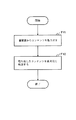
図3は、中継サーバM1の構成例を示すブロック図であり、通信インターフェース部11と、制御部12と、蓄積部13とを備えている。以下に、各構成要素について説明する。尚、他の中継サーバM2,M3も中継サーバM1と同様の構成を有している。
【0039】
●通信インターフェース部11:制御部12に対しネットワークからのデータを送受信する。
【0040】
●蓄積部13:様々なコンテンツ,コンテンツサマリーを一時的に蓄積する。
【0041】
●制御部12:中継制御キャッシュサーバから取得するコンテンツ,コンテンツサマリー及びその取得先のサーバ(Web サーバ,中継制御キャッシュサーバ,中継サーバ)が指示されると、取得先のサーバに対して上記コンテンツ,コンテンツサマリーの転送を要求する。そして、この要求に応答してコンテンツ,コンテンツサマリーが転送されてくると、蓄積部13に蓄積する。また、中継制御キャッシュサーバ,中継サーバからコンテンツ等の転送が要求された場合は、蓄積部13に蓄積されているコンテンツ等を取り出し、要求元へ転送する。
【0042】
記録媒体K2は、ディスク,半導体メモリ,その他の記録媒体であり、コンピュータを中継サーバM1として機能させるためのプログラムが記録されている。このプログラムは、コンピュータによって読み取られ、コンピュータの動作を制御することで、コンピュータ上に通信インターフェース部11,制御部12を実現する。
【0043】
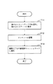
図4は中継制御キャッシュサーバC1,C2の処理例を示す流れ図、図5,図6は中継サーバM1〜M3の処理例を示す流れ図であり、以下、各図を参照して本実施の形態の動作を詳細に説明する。
【0044】
中継制御キャッシュサーバC1,C2内のリンク先読み制御部3,自動キャッシュ更新部4,或いはキャッシュサーバ連携部5は、リンク先読み動作,自動キャッシュ更新動作,或いはキャッシュサーバ連携動作に於いて、コンテンツ,コンテンツサマリーを取得する場合、取得するコンテンツ,コンテンツサマリーを特定する情報を中継制御部6に渡す(図4,F41)。尚、この情報には、上記コンテンツ,コンテンツサマリーを保持しているサーバのネットワークアドレス及び上記コンテンツ,コンテンツサマリーのIDが含まれている。
【0045】
今、例えば、中継制御キャッシュサーバC1内の自動キャッシュ更新部4が、Web サーバS1が所持しているコンテンツαを取得しようとして、中継制御部6に、Web サーバS1のネットワークアドレスと、コンテンツαのIDとを渡したとする(F41)。これにより、中継制御部6は、自動キャッシュ更新部4から渡されたWeb サーバS1のネットワークアドレスと、予め認識している各中継サーバM1〜M3のネットワークアドレスと、経路情報記憶部7に記憶されている経路情報とに基づいて、コンテンツαの転送に使用する中継サーバを決定する(F42)。
【0046】
尚、経路情報記憶部7には、図7に示すような経路情報が記憶されている。経路情報中の項目「ルータアドレス」は、ルータのネットワークアドレスを示し、「リンク」は、次ホップルータとの間に存在するリンクを示し、「次ホップルータアドレス」は、次ホップルータのネットワークアドレスを示し、「接続機器アドレス」は、ルータに接続される端末,Web サーバ,中継制御キャッシュサーバ,中継サーバ等の機器のネットワークアドレスを示している。
【0047】
また、本実施の形態に於いては、ステップF42に於いて、コンテンツαの転送に使用する中継サーバを決定する際、要求元の中継制御キャッシュサーバC1と、コンテンツαを所持しているWeb サーバ1との間に設定される経路(ルータのルーティングテーブルの内容によって決定される経路)上に存在する全ての中継サーバをコンテンツの転送に使用する中継サーバとする。今、例えば、中継制御キャッシュサーバC1とWeb サーバS1との間に設定される経路が、C1→R6→L5→R5→L4→R4→L3→R3→L2→R2→L1→R1→S1であるとすると、中継制御部6は、中継サーバM1,M2をコンテンツの転送に使用する中継サーバとする。このように、経路上に存在する全ての中継サーバを使用することにより、一時に使用するネットワークの資源が減少し、他のトラフィックに対する影響を小さくすることが可能となる。しかし、中継するサーバ数が増えれば、コンテンツが最終目的地へ転送されるまでに時間がかかってしまう。そこで、転送するコンテンツの緊急度に応じて、中継する中継サーバ数を可変にすることもできる。例えば、コンテンツの緊急度を、コンテンツの更新頻度等を元に決定し、その緊急度が高いものは、中継するサーバ数を少なく、また緊急度が低いものは、中継するサーバ数を多くするといった方法が考えられる。
【0048】
その後、中継制御部6は、ステップF42で使用することを決定した中継サーバM1,M2の内の、最も上流側に位置する中継サーバM2に対して、取得するコンテンツαのID及びその取得先のWeb サーバS1を指示する(F44)。尚、本実施の形態では、中継制御キャッシュサーバC1とWeb サーバS1との間に設定される経路上に中継サーバが存在せず、ステップF42に於いて使用する中継サーバを決定することができなかった場合は、中継制御部6は、コンテンツαを元々保持しているWeb サーバS1に対して、コンテンツαの転送を要求するものとするが、次のような方法も採用することができる。中継サーバ数を転送するコンテンツの緊急度に応じて、ある数(Nとする)以下と決め、先ず中継サーバ数をNとして、経由するリンク数の合計が最小となるように、経由するN個の中継サーバを求める。求められた場合は、そのN個の中継サーバを使用する中継サーバとする。求められなかった場合は、中継サーバ数を−1してN−1とし、経由するN−1個の中継サーバを求める。このような処理を、使用する中継サーバが求まるまで行う。尚、N=1としても使用する中継サーバが求まらなかった場合は、中継サーバを使用せずにコンテンツの転送を行う(コンテンツを元々保持しているサーバにコンテンツの転送を要求する)。
【0049】
コンテンツαのID及びWeb サーバS1を指示された中継サーバM2内の制御部12は、指示されたコンテンツαの転送を、指示されたWeb サーバS1に対して要求する(図5,F51)。これにより、Web サーバS1から中継サーバM2へ、S1→R1→L1→R2→L2→R3→M2の経路で、コンテンツαが転送される。
【0050】
中継サーバM2内の制御部12は、Web サーバS1からコンテンツαが転送されてくると、それを蓄積部13に蓄積した後、蓄積完了を要求元の中継制御キャッシュサーバC1に通知する(F52,F53)。
【0051】
中継制御キャッシュサーバC1内の中継制御部6は、中継サーバM2からコンテンツαの蓄積完了が通知されると、ステップF41で決定した中継サーバの中に未使用の中継サーバが存在するか否かを調べる(図4,F43)。そして、未使用の中継サーバが存在する場合は、その内の最も上流側に位置する中継サーバに対して取得するコンテンツαと、その取得先を指示する(F44)。これに対して、未使用の中継サーバが存在しない場合には、ステップF45の処理を行う。この例の場合は、未使用の中継サーバM1が存在するので、中継制御部6は、中継サーバM1に対して、取得するコンテンツαのID及びその取得先の中継サーバM2を指示する(F44)。
【0052】
この指示を受けた中継サーバM1内の制御部12は、図5の流れ図に示すように、中継サーバM2に対してコンテンツαの転送を要求する(F51)。これにより、中継サーバM2内の制御部12は、図6の流れ図に示すように、自サーバ内の蓄積部13に蓄積されているコンテンツαを取り出し、M2→R3→L3→R4→L4→R5→M1の経路で要求元の中継サーバM1へ転送する(F61,F62)。
【0053】
中継サーバM1内の制御部12は、中継サーバM2からコンテンツαが転送されてくると、図5の流れ図に示すように、コンテンツαを蓄積部13に蓄積し、その後、中継制御キャッシュサーバC1にコンテンツαの蓄積完了を通知する(F52,F53)。
【0054】
この通知を受けると、中継制御キャッシュサーバC1内の中継制御部6は、ステップF42で決定した中継サーバM1,M2の中に未使用の中継サーバが存在するか否かを調べる(図4,F43)。この例の場合、中継サーバM1,M2は既に両方とも使用しているので、ステップF43の判断結果はNOとなり、ステップF45の処理が行われる。
【0055】
ステップF45に於いては、中継制御キャッシュサーバC1は、ステップF42で決定した中継サーバM1,M2の内の、最下流に位置する中継サーバM1に対してコンテンツαを中継制御キャッシュサーバC1に転送することを要求する。この要求を受けた中継サーバM1内の制御部12は、図6の流れ図に示すように、蓄積部13に蓄積されているコンテンツαを取り出し、M1→R5→L5→R6→C1の経路で要求元の中継制御キャッシュサーバC1へ転送する(F61,F62)。
【0056】
中継制御キャッシュサーバC1内の自動キャッシュ更新部4は、中継サーバM1からコンテンツαが送られてくると、それを取得し、記憶装置8に格納する(F46)。
【0057】
【第2の実施の形態】
次に、本発明の第2の実施の形態について説明する。
【0058】
図8は本発明のネットワークシステムの第2の実施の形態の構成例を示すブロック図である。同図に示すように、第1の地域N1には、Web サーバS1と、中継制御キャッシュサーバC2aと、端末T1と、中継サーバM1,M2と、ルータR1〜R3,R8とが設けられている。また、第1の地域N1と時差を有する第2の地域N2には、Web サーバS2と、中継制御キャッシュサーバC1aと、端末T2と、中継サーバM3〜M5と、ルータR4〜R7とが設けられている。各ルータR1〜R8は、リンクL1〜L9により接続されている。
【0059】
図9は中継制御キャッシュサーバC1aの構成例を示すブロック図である。同図に示した中継制御キャッシュサーバC1aは、中継タイミング記憶部9が追加されている点、中継制御部6の代わりに中継制御部6aを備えている点、及び記録媒体K1の代わりに記録媒体K3を備えている点が、図2に示した中継制御キャッシュサーバC1と相違している。尚、中継制御キャッシュサーバC2aも同様の構成を有している。
【0060】
中継タイミング記憶部9には、各中継サーバM1〜M5毎に、その中継サーバに中継動作を行わせるのに適当な時間帯が記録されている。この時間帯は、中継サーバM1〜M5が設置されている地域に於いて、トラフィックが少なくなると予想される時間帯とする。
【0061】
中継制御部6aは、中継制御部6が備えている機能に加え、中継サーバMi(1≦i≦5)に対して、コンテンツ等を中継させるために指示を出すことが必要になった場合、中継タイミング記憶部9を参照して中継サーバMi対応の時間帯を求め、その時間帯に於いて中継サーバMiに指示を出す機能を備えている。
【0062】
記録媒体K3は、ディスク,半導体メモリ,その他の記録媒体であり、コンピュータを中継制御キャッシュサーバC1aとして機能させるためのプログラムが記録されている。このプログラムは、コンピュータによって読み取られ、コンピュータの動作を制御することで、コンピュータ上に、通信インターフェース部1,キャッシュ動作部2,リンク先読み制御部3,自動キャッシュ更新部4,キャッシュサーバ連携部5,中継制御部6aを実現する。
【0063】
次に、本実施の形態の動作を、第2の地域N2に配置されている中継制御キャッシュサーバC1a内の自動キャッシュ更新部4が、第1の地域N1内のWeb サーバS1が保持しているコンテンツαを取得する場合を例にとって説明する。
【0064】
中継制御キャッシュサーバC1a内の自動キャッシュ更新部4は、Web サーバS1が所持しているコンテンツを取得する場合、中継制御部6aにWeb サーバS1のネットワークアドレスと、コンテンツαのIDとを渡す(図10,F101)。これにより、中継制御部6aは、自動キャッシュ更新部4から渡されたWeb サーバS1のネットワークアドレスと、予め認識している各中継サーバM1〜M5のネットワークアドレスと、経路情報記憶部7に記憶されている経路情報とに基づいて、コンテンツαの転送に使用する中継サーバを決定する(F102)。本実施の形態でも、第1の実施の形態と同様に、中継制御キャッシュサーバC1aとWeb サーバS1との間に設定される経路上に存在する全ての中継サーバを、コンテンツαの転送に使用する中継サーバとする。今、例えば、Web サーバS1と中継制御キャッシュサーバC1aとの間に設定される経路が、S1→R1→L1→R2→L2→R3→L3→R4→L4→R5→L5→R6→C1aであったとすると、中継制御部6aは、中継サーバM1〜M4をコンテンツαの転送に使用する中継サーバとする。
【0065】
その後、中継制御部6aは、中継タイミング記憶部9を参照し、ステップF102で使用することを決定した中継サーバM1〜M4の内の、最も上流側の中継サーバM1に対して設定され時間帯を求める。そして、現在時刻が上記時間帯内の時刻であれば(F104がYES)、中継サーバM1に対して取得するコンテンツαのID及びその取得先のWeb サーバS1を指示する(F105)。これに対して、現在時刻が上記時間帯外の時刻であれば(F104がNO)、上記時間帯になるのを待って、中継サーバM1に対して取得するコンテンツαのID及びその取得先のWeb サーバS1を指示する(F105)。尚、中継制御キャッシュサーバC1aとWeb サーバS1との間に設定される経路上に中継サーバが存在せず、ステップF102に於いて使用する中継サーバを決定することができなかった場合は、中継制御部6aは、コンテンツαを元々保持しているWeb サーバS1に対して、コンテンツαの転送を要求する。
【0066】
コンテンツαのID及びWeb サーバS1を指示された中継サーバM1内の制御部12(図3参照)は、指示されたコンテンツαの転送を、指示されたWeb サーバS1に対して要求する(図5,F51)。これにより、Web サーバS1から中継サーバM1へ、S1→R1→L1→R2→M1の経路で、コンテンツαが転送される。
【0067】
中継サーバM1内の制御部12は、Web サーバS1からコンテンツαが転送されてくると、それを蓄積部13に蓄積した後、蓄積完了を要求元の中継制御キャッシュサーバC1aに通知する(F52,F53)。
【0068】
中継制御キャッシュサーバC1a内の中継制御部6aは、中継サーバM1からコンテンツαの蓄積完了が通知されると、ステップF102で決定した中継サーバの中に、未使用の中継サーバが存在するか否かを調べる(図10,F103)。この例の場合、未使用の中継サーバM2〜M4が存在するので、ステップF103の判断結果はYESとなり、ステップF104の処理が行われる。
【0069】
ステップF104では、未使用の中継サーバM2〜M4の内の、最も上流側に位置する中継サーバM2に割り当てられている時間帯を中継タイミング記憶部9から取得し、現在時刻がその時間帯内か否かを調べる(F104)。そして、現在時刻が上記時間帯内の時刻であれば、中継サーバM2に対して、取得するコンテンツαのIDとその取得先の中継サーバM1を指示する(F105)。これに対して、現在時刻が上記時間帯外であれば、時間帯内になるのを待って、ステップF105の処理を行う。以下、前述した処理と同様の処理が行われ、コンテンツαが中継サーバM1,M2,M3を介して中継サーバM4へ送られる。
【0070】
中継サーバM4内の制御部12は、蓄積部13にコンテンツαを蓄積すると、蓄積完了を取得要求元の中継キャッシュサーバC1aに通知する(図5,F52,F53)。
【0071】
この通知を受けると、中継制御キャッシュサーバC1a内の中継制御部6aは、未使用の中継サーバが存在しないので、ステップF102で決定した中継サーバM1〜M4の内の、最下流に位置する中継サーバM4に対してコンテンツαを中継制御キャッシュサーバC1に転送することを要求する(F106)。この要求を受けた中継サーバM4内の制御部12は、図6の流れ図に示すように、蓄積部13に蓄積されているコンテンツαを取り出し、M4→R5→L5→R6→C1の経路で要求元の中継制御キャッシュサーバC1へ転送する(F61,F62)。
【0072】
中継制御キャッシュサーバC1内の自動キャッシュ更新部4は、中継サーバM1からコンテンツαが送られてくると、それを取得し、記憶装置8に格納する(F107)。
【0073】
尚、上述した第1,第2の実施の形態に於いては、中継制御キャッシュサーバが、中継サーバに対して中継タイミングを指示するようにしたが、各中継サーバが自身で中継タイミングを判断し、中継を行うような構成も採用できる。このような構成をとる場合、例えば、次のような方法(a),(b) をとることができる。
【0074】
(a) 近接の中継サーバへ測定のためのパケットを流して、遅延時間を継続的に測定しておき、遅延時間の少ない時間帯を推定する。そして、中継を行う場合、中継したい下流サーバが、遅延時間の短い時間帯になるのを待って、中継を行う。
(b) 近接の中継サーバへ測定のためのパケットを流して、遅延時間を継続的に測定しておき、平均的な遅延や変動がどれくらいあるかを調べておく。中継を行う場合、中継したい下流サーバへ測定パケットを流して遅延時間を測定し、既に調べてある平均値からのずれなどをみて、どれほど混雑しているかを判定する。そして、混雑していなければ、中継を行う。混雑していれば、しばらく待って測定パケットを流して再判定するという処理を繰り返す。
【0075】
【発明の効果】
以上説明したように、本発明は、緊急性を要さないコンテンツを転送する際、中継サーバを使用し、要求元と要求先との間に設定される経路を一部分ずつ使用してコンテンツを転送するようにしたので、経路全体を一度に使用する従来に技術に比較して或る時点に於ける帯域の消費量を少なくすることができ、その結果、他のトラフィックに与える影響を少なくすることができる。
【0076】
また、本発明は、各中継サーバが、自中継サーバに対して定められている時間帯(例えば、その中継サーバが配置されている地域に於いて、トラフィックが少なくなると予想される地域)に於いて中継動作を行うようにしたので、他のトラフィックに与える影響を更に少なくすることができる。
【図面の簡単な説明】
【図1】本発明の第1の実施の形態の構成例を示すブロック図である。
【図2】中継制御キャッシュサーバC1の構成例を示すブロック図である。
【図3】中継サーバM1の構成例を示すブロック図である。
【図4】中継制御キャッシュサーバC1,C2の処理例を示す流れ図である。
【図5】中継サーバM1〜M3の処理例を示す流れ図である。
【図6】中継サーバM1〜M3の処理例を示す流れ図である。
【図7】経路情報の一例を示す図である。
【図8】本発明の第2の実施の形態の構成例を示す図である。
【図9】中継制御キャッシュサーバC1aの構成例を示すブロック図である。
【図10】中継制御キャッシュサーバC1aの処理例を示す流れ図である。
【図11】従来のネットワークシステムの構成例を示すブロック図である。
【符号の説明】
S1,S2…Web サーバ
C1,C1a,C2…中継制御キャッシュサーバ
M1〜M5…中継サーバ
R1〜R8…ルータ
L1〜L9…リンク
1…通信インターフェース部
2…キャッシュ動作部
3…リンク先読み制御部
4…自動キャッシュ更新部
5…キャッシュサーバ連携部
6,6a…中継制御部
7…経路情報記憶部
8…記憶装置
9…中継タイミング記憶部
K1〜K3…記録媒体[0001]
BACKGROUND OF THE INVENTION
The present invention relates to a technology for transferring content that does not require urgency, such as content prefetched by a cache server, and more particularly to a content transfer technology that can reduce the influence on other traffic during content transfer.
[0002]
[Prior art]
Some contents transferred via the network require urgency, while other contents do not require urgency. Examples of content that does not require urgency include content that is prefetched by a cache server arranged on a network in order to shorten the access time of content by a terminal.
[0003]
FIG. 11 is a diagram showing a configuration example of a network system including a conventional cache server. Web servers S100 and S101, cache servers C100 and C101, terminals T1 and T2, routers R1 to R7, routers It is comprised from the link L1-L8 which connects between R1-R7.
[0004]
When a terminal (for example, T1) acquires content in a Web server (for example, S100), a certain cache server (for example, C100) acts as an intermediary. When there is an access request for the content in the Web server S100 from the terminal T1, the cache server C100 checks whether or not it holds the requested content.
[0005]
If not, ask the other cache server whether or not you have the above content, acquire the content from the cache server you have, or the web that originally owned the content Obtained from the server (original Web server) S100 and delivered to the terminal T1. At this time, the corresponding content may be held in the storage device in the cache server C100 at the same time.
[0006]
On the other hand, if it is held, the corresponding content held is transferred to the terminal T1. At that time, the last update date and time of the content is inquired to the original Web server S100, and if the held content is older than the last update date and time of the original Web server S100, the content of the original Web server S100 is transferred to the cache server C100. May be reacquired (update check operation).
[0007]
The cache server (C100, C101, etc.) is inquired as to whether or not the content is held not only from the terminal but also from another cache server. The operation in this case also mediates the access request from the terminal to the Web server. Same as the case.
[0008]
The cache server operates as described above. However, if the update check operation is not performed, even if the content of the web server that requested access is retained, it is older than the content retained by the web server (web server Content changes that do not reflect the content changes on the side), in such a case, old content is sent to the terminal. In addition, when performing an update check, if the old content is retained, the content is reacquired to the original Web server or the like, and thus it takes time for the terminal to obtain the content.
[0009]
From the above, in the cache server, it is important to hold the latest content that is highly likely to be accessed from the terminal. For this reason, the cache server performs (1) automatic cache update operation, (2) link prefetch operation, and (3) cache server cooperation operation.
[0010]
(1) Automatic cache update operation refers to the operation of accessing the original Web server etc. for the content held by the cache server, and if there is content update, reacquires the content and obtains the latest content It is.
[0011]
(2) Link prefetching operation refers to the operation of acquiring the content specified by the link for the link described in the content (specifying the location with related information) held by the cache server. It is.
[0012]
(3) The cache server cooperative operation is an operation for redistributing, sharing, and comparing freshness of caches held by each cache server among a plurality of cache servers. The cache redistribution is an operation in which a cache server not having a certain content obtains the content from the cache server having the certain content. Cache sharing is an operation in which when a cache server that does not have a certain content receives an access request for the content from a terminal, the access request is transferred to the cache server that has the content. Cache freshness comparison refers to verifying that a cache server with certain content does not have a newer version of the same content (reflecting more recent content changes on the web server) The operation is to acquire a new version of the content as necessary. For these cache server cooperation operations, the conventional cache server exchanges information (content summary) indicating the effectiveness of each cache server as a cache of the contents and the contents of each cache server with other cache servers. I was doing processing. As the information indicating the validity as a cache, for example, the cache expiration date designated by the content origin server and the last update date and time of the content are used.
[0013]
By the way, acquisition of contents and content summaries associated with the above-described automatic cache update operation, link prefetching operation, and cache server cooperation operation is performed as follows.
[0014]
Now, for example, when the cache server C100 acquires a certain content from the Web server S100 in the automatic cache update operation or the link prefetching operation, the cache server C100 accesses the certain content addressed to the Web server S100. Send the request to the network. This access request is sent to the Web server S100 via a route (for example, R6->L5->R5->L4->R4->L3->R3->L2->R2->L1-> R1) determined by the contents of the routing table in each router. . The Web server S100 that has received the access request transfers the requested content to the cache server C100.
[0015]
For example, when the cache server C100 acquires content and content summary from the cache server C101, the cache server C100 sends an access request for the content and content summary addressed to the cache server C101 to the network. This access request is sent to the cache server C101 via the route R6->L5->R5->L4->R4->L3->R3->L2-> R2 determined by the contents of the routing table. The cache server C101 transfers the content and content summary requested by the access request to the cache server C100.
[0016]
[Problems to be solved by the invention]
By the way, the automatic cache update operation, the link prefetching operation, and the cache server cooperation operation basically predict the content that the terminal will need, and before the terminal actually accesses the corresponding content, This is an operation of obtaining from the Web server and cache server, and does not require urgency. Therefore, it is desirable to prevent as much as possible other traffic that requires urgency, such as traffic generated because the terminal actually needs content. However, with the above-described conventional technology, bandwidth transfer is simultaneously performed in all paths from the web server that owns the content and the cache server that requests the content to the cache server that requests the content by transferring the content associated with the link prefetching operation. Is consumed, so that there is a problem that it easily affects other traffic. In particular, when the number of hops between the content request source and the request destination is large, the bandwidth consumption in the entire route is considerably increased, which significantly affects other traffic.
[0017]
OBJECT OF THE INVENTION
Therefore, an object of the present invention is to reduce the influence of the transfer of content that does not require urgency on other traffic.
[0018]
[Means for Solving the Problems]
In order to achieve the above object, the content transfer method of the present invention possesses a request source such as a cache server and the content when transferring content that does not require urgency, such as content that is prefetched by the cache server. The content is transferred using a relay server existing on the route set with the existing server. According to this configuration, since only a part of the route set between the server and the request source is used at a certain point in time, the conventional technology in which the entire route is used at once is used. In comparison, the bandwidth consumption can be reduced, and as a result, the influence on other traffic can be reduced.
[0019]
In addition, in the content transfer method of the present invention, each relay server performs a relay operation in a time zone defined for the relay server in order to further reduce the influence on other traffic. Here, the time zone is a time zone in which traffic is expected to be low in the area where the relay server is located.
[0020]
DETAILED DESCRIPTION OF THE INVENTION
Next, embodiments of the present invention will be described in detail with reference to the drawings.
[0021]
[First Embodiment]
FIG. 1 is a block diagram showing a first embodiment of the network system of the present invention. As shown in the figure, the network system of the present embodiment includes Web servers S1 and S2, relay control cache servers C1 and C2, relay servers M1 to M3, terminals T1 and T2, and routers R1 to R7. , Links L1 to L8 connecting the routers R1 to R7. Here, it is effective to arrange the relay server adjacent to a router having a large number of links connected to other routers (for example, the router R3 having three links in FIG. 1). It is. This is because such a relay server has a high probability of being on the content delivery route, and when relaying content, it can relay without significantly changing the route, compared to the case of not relaying, thus reducing network resource consumption. Because it is possible. In other words, the route that is determined by the contents of the routing table that is used when relaying is not performed is generally the route that has the smallest number of hops and the least resource consumption. This is because a route to which no is added is a route that can reduce resource consumption. It is also effective to arrange a relay server adjacent to a large bandwidth link. This is because installing a relay server in the vicinity of a router increases traffic to the router and increases the risk of using up the link bandwidth. However, if the router is connected to a link with a large bandwidth, the risk is high. It is because it is possible to make low.
[0022]
Web servers S1 and S2 hold various contents. Terminals T1 and T2 access Web servers S1 and S2. The relay control cache servers C1 and C2 are on the Web servers S1 and S2 that have received access requests from the terminals T1 and T2 and other cache servers (either a relay control cache server or a conventional cache server not shown). Holds a copy of the content. When the content to be acquired and its acquisition destination are instructed from the relay control cache servers C1 and C2 that are content acquisition request sources, the relay servers M1 to M3 acquire the instructed content from the instructed acquisition destination, Is temporarily stored inside. Moreover, each router R1-R7 performs a routing process based on a routing table.
[0023]
When a terminal (for example, T1) acquires content in a Web server (for example, S1), a certain relay control cache server (for example, C1) mediates the content. When there is an access request from the terminal T1, the relay control cache server C1 checks whether or not the corresponding content is held by itself.
[0024]
If not, the other cache server is inquired whether or not the content is possessed, and the relevant content is acquired from the possessed cache server, or the relevant content is originally possessed. Obtained from the original Web server S1 and delivered to the terminal T1.
[0025]
On the other hand, when the content is held by itself, the content is transferred to the terminal T1. At that time, the last update date and time of the content is inquired to the original Web server S1, and if the held content is older than the last update date and time of the original Web server S1, the content of the original Web server S1 is relayed to the relay control cache. The server C1 acquires again (update check operation).
[0026]
The relay control cache servers C1 and C2 are inquired as to whether or not the contents are held not only from the terminal but also from other cache servers. The operation in this case is also a case where the access from the terminal to the Web server is mediated. It is the same.
[0027]
In addition, in order to increase the effectiveness of the relay control cache servers (C1, C2, etc.), as with the conventional cache server described above, (1) automatic cache update operation, (2) link prefetch operation, (3) cache Perform server linkage operations. However, with regard to the communication required for performing these operations, conventionally, the route (depending on the contents of the routing table) set between the web server etc. that owns the content and the relay control cache server that is the content request source. In this embodiment, the route is divided into a plurality of parts by using a relay server existing on the route. The content is transferred by sequentially using from the upstream side.
[0028]
FIG. 2 is a block diagram illustrating a configuration example of the relay control cache server C1. The
[0029]
Communication interface unit 1: Sends and receives data from the network to the
[0030]
Cache operation unit 2: Receives an access request to the content from the terminal via the
[0031]
Link prefetch control unit 3: The storage device in the link to the related information (indicating the location on the network where the related information is stored) described in the content stored in the storage device 8 Although there is no content indicated by the link in 8, there is a content that is likely to be accessed from now on. For example, among a plurality of links described in the content, a link that is a predetermined number of links from the top and that is likely to be accessed from now on when there is no related content in the storage device 8 associated information. And Then, the found link is transferred to the
[0032]
Automatic cache update unit 4: For the content stored in the storage device 8, the update interval of the content content on the original Web server where the content originally existed is checked, and the date and time when the cache content is updated is determined. Then, at the determined date and time, the network address of the Web server holding the corresponding content and the ID of the content are passed to the
[0033]
Cache server cooperation part 5: Redistribution, sharing, and freshness comparison between cache servers, so the cache server lists the contents of each cache server and shows the effectiveness of each cache server as a cache of the contents Information (content summary) is exchanged with other cache servers, and content is exchanged as necessary based on the information. When acquiring content and content summary, the network address of the corresponding content and web server holding the content summary and the cache server and the ID of the content and content summary are passed to the
[0034]
Route information storage unit 7: Stores route information indicating the network configuration.
[0035]
Relay control unit 6: Receives information (network address and ID) for specifying the content and content summary to be acquired from the link
[0036]
Storage device 8: Various contents and content summaries are stored.
[0037]
The recording medium K1 is a disk, semiconductor memory, or other recording medium, and stores a program for causing the computer to function as the relay control cache server C1. This program is read by the computer and controls the operation of the computer, so that the
[0038]
FIG. 3 is a block diagram illustrating a configuration example of the relay server M1, and includes a
[0039]
Communication interface unit 11: Sends and receives data from the network to the
[0040]
Storage unit 13: temporarily stores various contents and content summaries.
[0041]
Control unit 12: When the content to be acquired from the relay control cache server, the content summary, and the acquisition destination server (Web server, relay control cache server, relay server) are instructed, the content, Request transfer of content summary. When content and content summaries are transferred in response to this request, they are stored in the
[0042]
The recording medium K2 is a disk, semiconductor memory, or other recording medium, and stores a program for causing the computer to function as the relay server M1. This program is read by a computer and controls the operation of the computer, thereby realizing the
[0043]
FIG. 4 is a flowchart showing an example of processing of the relay control cache servers C1 and C2, and FIGS. 5 and 6 are flowcharts showing examples of processing of the relay servers M1 to M3. The operation will be described in detail.
[0044]
The link
[0045]
Now, for example, the automatic
[0046]
The route
[0047]
In the present embodiment, when determining the relay server to be used for transferring the content α in step F42, the requesting relay control cache server C1 and the web server possessing the content α are included. It is assumed that all relay servers existing on the route set between the two (route determined by the contents of the router routing table) are used for content transfer. Now, for example, the path set between the relay control cache server C1 and the Web server S1 is C1, R6, L5, R5, L4, R4, L3, R3, L2, R2, L1, R1, S1. Then, the
[0048]
Thereafter, the
[0049]
The
[0050]
When the content α is transferred from the Web server S1, the
[0051]
When the
[0052]
Upon receiving this instruction, the
[0053]
When the content α is transferred from the relay server M2, the
[0054]
Upon receiving this notification, the
[0055]
In step F45, the relay control cache server C1 transfers the content α to the relay control cache server C1 for the relay server M1 located at the most downstream of the relay servers M1 and M2 determined in step F42. Request that. Upon receiving this request, the
[0056]
When the content α is sent from the relay server M1, the automatic
[0057]
[Second Embodiment]
Next, a second embodiment of the present invention will be described.
[0058]
FIG. 8 is a block diagram showing a configuration example of the second embodiment of the network system of the present invention. As shown in the figure, the first region N1 is provided with a Web server S1, a relay control cache server C2a, a terminal T1, relay servers M1 and M2, and routers R1 to R3 and R8. . Further, in the second region N2 having a time difference from the first region N1, a Web server S2, a relay control cache server C1a, a terminal T2, relay servers M3 to M5, and routers R4 to R7 are provided. ing. The routers R1 to R8 are connected by links L1 to L9.
[0059]
FIG. 9 is a block diagram illustrating a configuration example of the relay control cache server C1a. The relay control cache server C1a shown in the figure is provided with a relay
[0060]
In the relay
[0061]
In addition to the functions provided in the
[0062]
The recording medium K3 is a disk, semiconductor memory, or other recording medium, and stores a program for causing the computer to function as the relay control cache server C1a. This program is read by a computer and controls the operation of the computer, so that the
[0063]
Next, the operation of this embodiment is held by the automatic
[0064]
The automatic
[0065]
Thereafter, the relay control unit 6a refers to the relay
[0066]
The control unit 12 (see FIG. 3) in the relay server M1 instructed with the ID of the content α and the Web server S1 requests the instructed Web server S1 to transfer the instructed content α (FIG. 5). , F51). As a result, the content α is transferred from the Web server S1 to the relay server M1 through a route of S1, R1, L1, R2, and M1.
[0067]
When the content α is transferred from the Web server S1, the
[0068]
When the relay control unit 6a in the relay control cache server C1a is notified of the completion of storage of the content α from the relay server M1, whether or not there is an unused relay server among the relay servers determined in step F102. Is examined (FIG. 10, F103). In this example, since there are unused relay servers M2 to M4, the determination result of step F103 is YES, and the process of step F104 is performed.
[0069]
In Step F104, the time zone assigned to the relay server M2 located on the most upstream side among the unused relay servers M2 to M4 is acquired from the relay
[0070]
When the content α is stored in the
[0071]
Upon receiving this notification, the relay control unit 6a in the relay control cache server C1a has no unused relay server, so the relay server located at the most downstream of the relay servers M1 to M4 determined in step F102. Request M4 to transfer the content α to the relay control cache server C1 (F106). Upon receiving this request, the
[0072]
When the content α is sent from the relay server M1, the automatic
[0073]
In the first and second embodiments described above, the relay control cache server instructs the relay server to specify the relay timing. However, each relay server determines the relay timing by itself. A configuration that performs relaying can also be adopted. When taking such a configuration, for example, the following methods (a) and (b) can be taken.
[0074]
(a) A measurement packet is sent to a nearby relay server, the delay time is continuously measured, and a time zone with a short delay time is estimated. And when relaying, it waits for the downstream server which wants to relay to become a time slot | zone with a short delay time, and relays.
(b) Flow measurement packets to nearby relay servers and measure the delay time continuously to find out how much average delay or fluctuation is present. When relaying, a measurement packet is sent to a downstream server to be relayed, the delay time is measured, and a deviation from the average value that has already been checked is determined to determine how congested it is. If it is not crowded, relay is performed. If it is congested, the process of waiting for a while and then re-determining the measurement packet is repeated.
[0075]
【The invention's effect】
As described above, according to the present invention, when transferring content that does not require urgency, the relay server is used and the content is transferred partially using a route set between the request source and the request destination. As a result, the bandwidth consumption at a certain point in time can be reduced compared to the conventional technology that uses the entire route at once, and as a result, the influence on other traffic can be reduced. Can do.
[0076]
In addition, the present invention is such that each relay server is in a time zone (for example, an area where traffic is expected to decrease in an area where the relay server is located) that is set for the relay server. Since the relay operation is performed, the influence on other traffic can be further reduced.
[Brief description of the drawings]
FIG. 1 is a block diagram showing a configuration example of a first exemplary embodiment of the present invention.
FIG. 2 is a block diagram illustrating a configuration example of a relay control cache server C1.
FIG. 3 is a block diagram illustrating a configuration example of a relay server M1.
FIG. 4 is a flowchart showing a processing example of relay control cache servers C1 and C2.
FIG. 5 is a flowchart showing a processing example of relay servers M1 to M3.
FIG. 6 is a flowchart illustrating a processing example of relay servers M1 to M3.
FIG. 7 is a diagram illustrating an example of route information.
FIG. 8 is a diagram illustrating a configuration example of a second embodiment of the present invention.
FIG. 9 is a block diagram illustrating a configuration example of a relay control cache server C1a.
FIG. 10 is a flowchart showing a processing example of the relay control cache server C1a.
FIG. 11 is a block diagram illustrating a configuration example of a conventional network system.
[Explanation of symbols]
S1, S2 ... Web server
C1, C1a, C2 ... Relay control cache server
M1 to M5: Relay server
R1-R8 ... Router
L1-L9 ... Link
1. Communication interface part
2 ... Cache operation part
3. Link prefetch control unit
4 ... Automatic cache update unit
5 ... Cache server cooperation department
6, 6a ... Relay control unit
7. Route information storage unit
8. Storage device
9 ... Relay timing storage unit
K1 to K3 ... Recording medium
Claims (21)
前記ネットワーク上に存在するルータによって設定される前記サーバと前記キャッシュサーバとの間の経路上に存在する各中継サーバが、自中継サーバよりも上流側に位置している前記コンテンツを保持している中継サーバ或いは前記サーバに対して前記コンテンツの転送を要求し、該要求に応答して前記経路を介して転送されてきた前記コンテンツを自中継サーバ内に一時的に蓄積し、自中継サーバよりも下流側に位置する中継サーバ或いは前記キャッシュサーバから前記コンテンツの転送が要求された場合、前記蓄積しているコンテンツを前記経路を介して要求元へ転送することを特徴とするコンテンツ転送方法。A content transfer method for transferring the content from a server having the content to the cache server via a network in order to keep the latest content that is likely to be accessed from a terminal in the cache server. And
Each relay server existing on the path between the server and the cache server set by the router existing on the network holds the content located upstream from the own relay server. The relay server or the server is requested to transfer the content, and the content transferred via the route in response to the request is temporarily stored in the own relay server. A content transfer method , wherein when the transfer of the content is requested from a relay server or the cache server located downstream, the stored content is transferred to the request source via the route .
前記コンテンツの転送は、前記キャッシュサーバが行う自動キャッシュ更新動作,リンク先読み動作或いはキャッシュサーバ連携動作に伴って行われるものであることを特徴とするコンテンツ転送方法。The content transfer method according to claim 1 ,
The content transfer method according to claim 1, wherein the content transfer is performed in association with an automatic cache update operation, a link prefetch operation, or a cache server cooperation operation performed by the cache server.
前記ネットワーク上に存在する各中継サーバが、自中継サーバに対して予め決められている時間帯に於いて、自中継サーバよりも上流側に位置している前記コンテンツを保持している中継サーバ或いは前記サーバに対して前記コンテンツの転送を要求することを特徴とするコンテンツ転送方法。The content transfer method according to claim 1 ,
Each relay server existing on the network holds the content located upstream from the own relay server in a predetermined time zone with respect to the own relay server, or content transfer wherein a main Motomesu Rukoto transfer of the content to the server.
前記中継サーバに対して決められている時間帯は、前記中継サーバが設置されている地域に於いてトラフィックが少ないと予想される時間帯であることを特徴とするコンテンツ転送方法。In the content transfer method according to claim 3 ,
2. The content transfer method according to claim 1, wherein the time zone determined for the relay server is a time zone in which traffic is expected to be low in an area where the relay server is installed.
前記ネットワーク上に存在するルータによって設定される前記サーバと前記要求元との間の経路上に存在する中継サーバの内の、前記コンテンツの緊急度に応じた台数の中継サーバが、前記経路上を転送される前記コンテンツを一時的に蓄積し、その後、自中継サーバに蓄積されている前記コンテンツを前記経路の自中継サーバよりも下流側に送出することを特徴とするコンテンツ転送方法。 A content transfer method for transferring content that does not require urgency from a server that possesses the content to a request source that requests acquisition of the content via a network,
Of the relay servers existing on the path between the server set by the router existing on the network and the request source, the number of relay servers corresponding to the urgency level of the content is on the path. A content transfer method characterized in that the content to be transferred is temporarily stored, and then the content stored in the self-relay server is sent downstream from the self-relay server on the route.
前記ネットワーク上に存在するルータによって設定される前記サーバと前記要求元との間の経路上に中継サーバが存在しない場合は、前記コンテンツの緊急度に応じた台数の中継サーバであって、且つ経由するリンク数の合計が最小となる中継サーバを、前記コンテンツの中継を行う中継サーバとすることを特徴とするコンテンツ転送方法。The content transfer method according to claim 5 , wherein
When there is no relay server on the route between the server and the request source set by the router existing on the network, the number of relay servers according to the urgency of the content, and via A content transfer method characterized in that a relay server that minimizes the total number of links to be used is a relay server that relays the content.
前記ネットワーク上に存在するルータによって設定される前記サーバと前記キャッシュサーバとの間の経路上に存在する中継サーバの内の、前記コンテンツの緊急度に応じた台数の中継サーバが、前記経路上を転送される前記コンテンツを一時的に蓄積し、その後、自中継サーバに蓄積されている前記コンテンツを前記経路の自中継サーバよりも下流側に送出することを特徴とするコンテンツ転送方法。The content transfer method according to any one of claims 1 to 4 ,
Of the relay servers existing on the path between the server and the cache server set by the router existing on the network, the number of relay servers corresponding to the urgency level of the content is on the path. A content transfer method characterized in that the content to be transferred is temporarily stored, and then the content stored in the self-relay server is sent downstream from the self-relay server on the route.
前記ネットワーク上に存在するルータによって設定される前記サーバと前記キャッシュサーバとの間の経路上に中継サーバが存在しない場合は、前記コンテンツの緊急度に応じた台数の中継サーバであって、且つ経由するリンク数の合計が最小となる中継サーバを、前記コンテンツの中継を行う中継サーバとすることを特徴とするコンテンツ転送方法。The content transfer method according to any one of claims 1 to 4 ,
When there is no relay server on the path between the server and the cache server set by the router existing on the network, the number of relay servers according to the urgency of the content, and via A content transfer method characterized in that a relay server that minimizes the total number of links to be used is a relay server that relays the content.
前記キャッシュサーバが、
端末からアクセスされる可能性の高い最新のコンテンツを取得する際、前記ルータによって設定される前記サーバとの間の経路上に存在する中継サーバに対して中継するコンテンツとして前記端末からアクセスされる可能性が高い最新のコンテンツを指示する中継制御部を備え、
前記中継サーバが、
蓄積部と、
前記キャッシュサーバから中継するコンテンツが指示された場合、自中継サーバよりも上流側に位置している前記コンテンツを保持している中継サーバ或いは前記サーバに対して前記コンテンツの転送を要求し、該要求に応答して前記経路を介して転送されてきた前記コンテンツを自中継サーバ内に一時的に蓄積し、自中継サーバよりも下流側に位置する中継サーバ或いは前記キャッシュサーバから前記コンテンツの転送が要求された場合、前記蓄積しているコンテンツを前記経路を介して要求元へ転送する制御部とを備えたことを特徴とするネットワークシステム。A cache server that requests acquisition of the latest content that is highly likely to be accessed from a terminal, a server that holds content requested by the cache server, a relay server that relays content, and a router Network system,
The cache server is
When acquiring the latest content that is highly likely to be accessed from the terminal, it can be accessed from the terminal as content to be relayed to a relay server that exists on the route to the server set by the router A relay control unit that instructs the latest content
The relay server is
A storage unit;
When content to be relayed is instructed from the cache server, a request is made to transfer the content to the relay server holding the content located upstream of the own relay server or the server, and the request The content transferred via the route in response to the request is temporarily stored in the own relay server, and the transfer of the content is requested from the relay server or the cache server located downstream from the own relay server. And a control unit that transfers the stored content to the request source via the route .
前記キャッシュサーバが、
端末からアクセスされる可能性の高い最新のコンテンツの取得を前記中継制御部に対して要求するリンク先読み制御部,自動キャッシュ更新部,或いはキャッシュサーバ連携部の内の少なくとも1つを備えたことを特徴とするネットワークシステム。The network system according to claim 9 , wherein
The cache server is
It is provided with at least one of a link prefetch control unit, an automatic cache update unit, or a cache server cooperation unit that requests the relay control unit to acquire the latest content that is highly likely to be accessed from a terminal. A characteristic network system.
前記キャッシュサーバが、
前記ネットワーク上に存在する各中継サーバ毎の、中継動作を行うのに適した時間帯が登録された中継タイミング記憶部を備え、
前記中継制御部が、
中継サーバに対して中継するコンテンツを指示する場合には、前記中継タイミング記憶部に登録されている前記中継サーバ対応の時間帯に於いて中継するコンテンツを指示する構成を有することを特徴とするネットワークシステム。The network system according to claim 9 , wherein
The cache server is
A relay timing storage unit in which a time zone suitable for performing a relay operation is registered for each relay server existing on the network,
The relay control unit
When instructing the contents to be relayed to the relay server, and wherein Rukoto that have a structure that instructs the content to be relayed at a time zone of the relay server correspondence that are registered to the relay timing storage unit Network system.
前記中継タイミング記憶部に登録される前記各中継サーバ毎の時間帯は、その中継サーバが配置されている地域に於いて、トラフィックが少なくなると予想される時間帯であることを特徴とするネットワークシステム。The network system according to claim 11 , wherein
The time zone for each relay server registered in the relay timing storage unit is a time zone in which traffic is expected to decrease in the area where the relay server is located. .
前記要求元が、
前記ルータによって設定される前記サーバとの間の経路上に存在する中継サーバの内の 、中継するコンテンツの緊急度に応じた台数の中継サーバに対して中継するコンテンツを指示する中継制御部を備え、
前記中継サーバが、
蓄積部と、
前記要求元によって指示されたコンテンツを前記経路を介して取得して前記蓄積部に蓄積し、その後、前記蓄積部に蓄積されている前記コンテンツを前記経路の自中継サーバよりも下流側に送出する制御部とを備えたことを特徴とするネットワークシステム。 A request source that requests acquisition of content that does not require urgency, a server that holds content that does not require urgency requested by the request source, a relay server that relays content, and a router A network system comprising:
The request source is
Of the relay server existing on a path between the server configured by the front Symbol router, the relay control unit for instructing the contents to be relayed to the relay server number corresponding to the urgency of the content to be relayed Prepared,
The relay server is
A storage unit;
The content instructed by the request source is acquired through the route and stored in the storage unit, and then the content stored in the storage unit is sent downstream from the own relay server of the route. A network system comprising a control unit .
前記中継制御部が、前記ルータによって設定される前記サーバとの間の経路上に中継サーバが存在しない場合は、中継するコンテンツの緊急度に応じた台数の中継サーバであって、且つ経由するリンク数の合計が最小となる中継サーバに対して中継するコンテンツを指示する構成を有することを特徴とするネットワークシステム。The network system according to claim 13 , wherein
When there is no relay server on the route between the relay control unit and the server set by the router, the number of relay servers according to the urgency of the content to be relayed, and the link through A network system having a configuration in which content to be relayed is instructed to a relay server having the smallest total number.
前記中継制御部が、前記ルータによって設定される前記サーバとの間の経路上に存在する中継サーバの内の、中継するコンテンツの緊急度に応じた台数の中継サーバに対して、中継するコンテンツとして前記端末からアクセスされる可能性が高い最新のコンテンツを指示する構成を有することを特徴とするネットワークシステム。The network system according to any one of claims 9 to 12 ,
As the content to be relayed to the number of relay servers according to the urgency of the content to be relayed among the relay servers existing on the route between the server and the server set by the router A network system characterized by indicating the latest content that is highly likely to be accessed from the terminal.
前記中継制御部が、前記ルータによって設定される前記サーバとの間の経路上に中継サーバが存在しない場合は、中継するコンテンツの緊急度に応じた台数の中継サーバであって、且つ経由するリンク数の合計が最小となる中継サーバに対して、中継するコンテンツとして前記端末からアクセスされる可能性が高い最新のコンテンツを指示する構成を有することを特徴とするネットワークシステム。The network system according to any one of claims 9 to 12 ,
When there is no relay server on the route between the relay control unit and the server set by the router, the number of relay servers according to the urgency of the content to be relayed, and the link through A network system having a configuration in which the latest content that is highly likely to be accessed from the terminal as the content to be relayed is instructed to the relay server having the smallest total number.
端末からアクセスされる可能性の高い最新のコンテンツの取得を要求するとき、前記ネットワーク上に存在するルータによって設定される前記サーバ用コンピュータとの間の経路上に存在する中継サーバ用コンピュータに対して中継するコンテンツとして前記端末からアクセスされる可能性の高い最新のコンテンツを指示する中継制御部として機能させ、
蓄積部を備えた前記中継サーバ用コンピュータを、
前記キャッシュサーバ用コンピュータから中継するコンテンツが指示された場合、自中継サーバ用コンピュータよりも上流側に位置している前記コンテンツを保持している中継サーバ用コンピュータ或いは前記サーバ用コンピュータに対して前記コンテンツの転送を要求し、該要求に応答して前記経路を介して転送されてきた前記コンテンツを自中継サーバ用コンピュータ内の前記蓄積部に一時的に蓄積し、自中継サーバ用コンピュータよりも下流側に位置する中継サーバ用サーバ或いは前記キャッシュサーバ用コンピュータから前記コンテンツの転送が要求された場合、前記蓄積しているコンテンツを前記経路を介して要求元へ転送する制御部として機能させるためのプログラムを記録した、プログラムを記録した機械読み取り可能な記録媒体。A cache server computer that requests acquisition of the latest content that is likely to be accessed from a terminal to a server computer connected via a network.
When requesting acquisition of the latest content that is highly likely to be accessed from a terminal, for a relay server computer that exists on the path to the server computer set by a router that exists on the network Function as a relay control unit that instructs the latest content that is likely to be accessed from the terminal as the content to be relayed;
The relay server computer provided with a storage unit,
When content to be relayed is instructed from the cache server computer, the content is sent to the relay server computer or the server computer that holds the content located upstream from the local relay server computer. The content that has been transferred via the path in response to the request is temporarily stored in the storage unit in the own relay server computer, and is further downstream than the own relay server computer. A program for functioning as a control unit for transferring the stored content to the request source via the route when the transfer of the content is requested from the relay server server or the cache server computer Recorded, machine readable record of recorded program Body.
前記ネットワーク上に存在するルータによって設定される前記サーバ用コンピュータとの間の経路上に存在する中継サーバ用コンピュータの内の、中継するコンテンツの重要度に応じた台数の中継サーバ用コンピュータに対して中継するコンテンツを指示する中継制御部として機能させるためのプログラムと、
蓄積部を備えた前記中継サーバ用コンピュータを、
前記要求元用コンピュータによって指示されたコンテンツを前記経路を介して取得して前記蓄積部に蓄積し、その後、前記蓄積部に蓄積されている前記コンテンツを前記経路の自中継サーバ用コンピュータよりも下流側に送出する制御部として機能させるためのプログラムとを記録した、プログラムを記録した機械読み取り可能な記録媒体。 A requesting computer that requests acquisition of content that does not require urgency to a server computer connected via a network,
For the number of relay server computers corresponding to the importance of the content to be relayed among the relay server computers existing on the path to the server computer set by the router existing on the network A program for functioning as a relay control unit for instructing content to be relayed;
The relay server computer provided with a storage unit,
The content instructed by the request source computer is acquired via the route and stored in the storage unit, and then the content stored in the storage unit is downstream from the self-relay server computer of the route. A machine-readable recording medium on which a program is recorded, which is recorded with a program for functioning as a control unit to be sent to the side .
前記中継制御部が、前記ルータによって設定される前記サーバ用コンピュータとの間の経路上に中継サーバ用コンピュータが存在しない場合は、中継するコンテンツの緊急度に応じた台数の中継サーバ用コンピュータであって、且つ経由するリンク数の合計が最小となる中継サーバ用コンピュータに対して中継するコンテンツを指示する構成を有することを特徴とするプログラムを記録した機械読み取り可能な記録媒体。A machine-readable recording medium in which the program according to claim 18 is recorded.
When there is no relay server computer on the route between the relay control unit and the server computer set by the router, the number of relay server computers according to the urgency of the content to be relayed. And a machine-readable recording medium storing a program, wherein the relay server computer has a configuration in which the content to be relayed is directed to a relay server computer having a minimum number of links.
前記中継制御部が、前記ルータによって設定される前記サーバ用コンピュータとの間の経路上に存在する中継サーバ用コンピュータの内の、中継するコンテンツの緊急度に応じた台数の中継サーバ用コンピュータに対して、中継するコンテンツとして前記端末からアクセスされる可能性が高い最新のコンテンツを指示する構成を有することを特徴とするプログラムを記録した機械読み取り可能な記録媒体。A machine-readable recording medium recording the program according to claim 17 ,
For the number of relay server computers corresponding to the urgency level of the content to be relayed, among the relay server computers existing on the route between the server computer and the server computer set by the router A machine-readable recording medium storing a program, characterized in that the latest content that is highly likely to be accessed from the terminal is indicated as relayed content.
前記中継制御部が、前記ルータによって設定される前記サーバ用コンピュータとの間の経路上に中継サーバ用コンピュータが存在しない場合は、中継するコンテンツの緊急度に応じた台数の中継サーバ用コンピュータであって、且つ経由するリンク数の合計が最小となる中継サーバ用コンピュータに対して、中継するコンテンツとして前記端末からアクセスされる可能性が高い最新のコンテンツを指示する構成を有することを特徴とするプログラムを記録した機械読み取り可能な記録媒体。A machine-readable recording medium recording the program according to claim 17 ,
When there is no relay server computer on the route between the relay control unit and the server computer set by the router, the number of relay server computers according to the urgency of the content to be relayed. And a relay server computer having the smallest total number of links through which the latest content that is likely to be accessed from the terminal as relayed content is designated. A machine-readable recording medium on which is recorded.
Priority Applications (2)
| Application Number | Priority Date | Filing Date | Title |
|---|---|---|---|
| JP2000224447A JP3674471B2 (en) | 2000-07-25 | 2000-07-25 | Content transfer method, network system, and machine-readable recording medium recording program |
| US09/915,058 US7222186B2 (en) | 2000-07-25 | 2001-07-24 | Content transferring technique |
Applications Claiming Priority (1)
| Application Number | Priority Date | Filing Date | Title |
|---|---|---|---|
| JP2000224447A JP3674471B2 (en) | 2000-07-25 | 2000-07-25 | Content transfer method, network system, and machine-readable recording medium recording program |
Publications (2)
| Publication Number | Publication Date |
|---|---|
| JP2002044137A JP2002044137A (en) | 2002-02-08 |
| JP3674471B2 true JP3674471B2 (en) | 2005-07-20 |
Family
ID=18718410
Family Applications (1)
| Application Number | Title | Priority Date | Filing Date |
|---|---|---|---|
| JP2000224447A Expired - Fee Related JP3674471B2 (en) | 2000-07-25 | 2000-07-25 | Content transfer method, network system, and machine-readable recording medium recording program |
Country Status (2)
| Country | Link |
|---|---|
| US (1) | US7222186B2 (en) |
| JP (1) | JP3674471B2 (en) |
Families Citing this family (107)
| Publication number | Priority date | Publication date | Assignee | Title |
|---|---|---|---|---|
| US6405219B2 (en) * | 1999-06-22 | 2002-06-11 | F5 Networks, Inc. | Method and system for automatically updating the version of a set of files stored on content servers |
| US8495167B2 (en) * | 2001-08-02 | 2013-07-23 | Lauri Valjakka | Data communications networks, systems, methods and apparatus |
| US20090006543A1 (en) * | 2001-08-20 | 2009-01-01 | Masterobjects | System and method for asynchronous retrieval of information based on incremental user input |
| US6910077B2 (en) * | 2002-01-04 | 2005-06-21 | Hewlett-Packard Development Company, L.P. | System and method for identifying cloaked web servers |
| JP2003281140A (en) * | 2002-03-20 | 2003-10-03 | Hitachi Ltd | Content distribution method and distribution system |
| EP1685501A1 (en) * | 2003-11-18 | 2006-08-02 | Nokia Corporation | Method, subject terminal device, target terminal device, data content server, system and computer programs for maintaining and updating data contents |
| US7624160B2 (en) * | 2004-05-04 | 2009-11-24 | International Business Machines Corporation | Methods, systems, and computer program products for client side prefetching and caching of portlets |
| US8856117B2 (en) * | 2004-10-29 | 2014-10-07 | Opentable, Inc. | System and method of accelerating response time to inquiries regarding inventory information in a network |
| US8001456B2 (en) * | 2005-02-28 | 2011-08-16 | International Business Machines Corporation | Methods for maintaining separation between markup and data at a client |
| US7774335B1 (en) * | 2005-08-23 | 2010-08-10 | Amazon Technologies, Inc. | Method and system for determining interest levels of online content navigation paths |
| US8719255B1 (en) | 2005-08-23 | 2014-05-06 | Amazon Technologies, Inc. | Method and system for determining interest levels of online content based on rates of change of content access |
| US7756130B1 (en) | 2007-05-22 | 2010-07-13 | At&T Mobility Ii Llc | Content engine for mobile communications systems |
| US8028090B2 (en) | 2008-11-17 | 2011-09-27 | Amazon Technologies, Inc. | Request routing utilizing client location information |
| US7991910B2 (en) | 2008-11-17 | 2011-08-02 | Amazon Technologies, Inc. | Updating routing information based on client location |
| KR100907613B1 (en) * | 2007-12-26 | 2009-07-14 | 에스케이 텔레콤주식회사 | Content providing server, system and method for providing additional content |
| US7962597B2 (en) | 2008-03-31 | 2011-06-14 | Amazon Technologies, Inc. | Request routing based on class |
| US8156243B2 (en) | 2008-03-31 | 2012-04-10 | Amazon Technologies, Inc. | Request routing |
| US8321568B2 (en) * | 2008-03-31 | 2012-11-27 | Amazon Technologies, Inc. | Content management |
| US8606996B2 (en) | 2008-03-31 | 2013-12-10 | Amazon Technologies, Inc. | Cache optimization |
| US7970820B1 (en) | 2008-03-31 | 2011-06-28 | Amazon Technologies, Inc. | Locality based content distribution |
| US8601090B1 (en) | 2008-03-31 | 2013-12-03 | Amazon Technologies, Inc. | Network resource identification |
| US8447831B1 (en) | 2008-03-31 | 2013-05-21 | Amazon Technologies, Inc. | Incentive driven content delivery |
| US8533293B1 (en) | 2008-03-31 | 2013-09-10 | Amazon Technologies, Inc. | Client side cache management |
| US9407681B1 (en) | 2010-09-28 | 2016-08-02 | Amazon Technologies, Inc. | Latency measurement in resource requests |
| US7925782B2 (en) | 2008-06-30 | 2011-04-12 | Amazon Technologies, Inc. | Request routing using network computing components |
| US9912740B2 (en) | 2008-06-30 | 2018-03-06 | Amazon Technologies, Inc. | Latency measurement in resource requests |
| US8521880B1 (en) | 2008-11-17 | 2013-08-27 | Amazon Technologies, Inc. | Managing content delivery network service providers |
| US8065417B1 (en) | 2008-11-17 | 2011-11-22 | Amazon Technologies, Inc. | Service provider registration by a content broker |
| US8732309B1 (en) | 2008-11-17 | 2014-05-20 | Amazon Technologies, Inc. | Request routing utilizing cost information |
| US8073940B1 (en) | 2008-11-17 | 2011-12-06 | Amazon Technologies, Inc. | Managing content delivery network service providers |
| US8060616B1 (en) | 2008-11-17 | 2011-11-15 | Amazon Technologies, Inc. | Managing CDN registration by a storage provider |
| US8122098B1 (en) | 2008-11-17 | 2012-02-21 | Amazon Technologies, Inc. | Managing content delivery network service providers by a content broker |
| US20100241580A1 (en) | 2009-03-19 | 2010-09-23 | Tagged, Inc. | System and method of selecting a relevant user for introduction to a user in an online environment |
| US8412823B1 (en) | 2009-03-27 | 2013-04-02 | Amazon Technologies, Inc. | Managing tracking information entries in resource cache components |
| US8521851B1 (en) | 2009-03-27 | 2013-08-27 | Amazon Technologies, Inc. | DNS query processing using resource identifiers specifying an application broker |
| US8688837B1 (en) | 2009-03-27 | 2014-04-01 | Amazon Technologies, Inc. | Dynamically translating resource identifiers for request routing using popularity information |
| US8756341B1 (en) | 2009-03-27 | 2014-06-17 | Amazon Technologies, Inc. | Request routing utilizing popularity information |
| US8782236B1 (en) | 2009-06-16 | 2014-07-15 | Amazon Technologies, Inc. | Managing resources using resource expiration data |
| US8397073B1 (en) | 2009-09-04 | 2013-03-12 | Amazon Technologies, Inc. | Managing secure content in a content delivery network |
| JP5231368B2 (en) * | 2009-09-15 | 2013-07-10 | ヤフー株式会社 | Event notification function providing system |
| US8433771B1 (en) | 2009-10-02 | 2013-04-30 | Amazon Technologies, Inc. | Distribution network with forward resource propagation |
| EP2317728B1 (en) * | 2009-10-27 | 2013-04-10 | Alcatel Lucent | Method, apparatus, and server for spreading file transfer notifications in time |
| US9495338B1 (en) | 2010-01-28 | 2016-11-15 | Amazon Technologies, Inc. | Content distribution network |
| US8756272B1 (en) | 2010-08-26 | 2014-06-17 | Amazon Technologies, Inc. | Processing encoded content |
| US9003035B1 (en) | 2010-09-28 | 2015-04-07 | Amazon Technologies, Inc. | Point of presence management in request routing |
| US9712484B1 (en) | 2010-09-28 | 2017-07-18 | Amazon Technologies, Inc. | Managing request routing information utilizing client identifiers |
| US8938526B1 (en) | 2010-09-28 | 2015-01-20 | Amazon Technologies, Inc. | Request routing management based on network components |
| US8577992B1 (en) | 2010-09-28 | 2013-11-05 | Amazon Technologies, Inc. | Request routing management based on network components |
| US10958501B1 (en) | 2010-09-28 | 2021-03-23 | Amazon Technologies, Inc. | Request routing information based on client IP groupings |
| US8930513B1 (en) | 2010-09-28 | 2015-01-06 | Amazon Technologies, Inc. | Latency measurement in resource requests |
| US8924528B1 (en) | 2010-09-28 | 2014-12-30 | Amazon Technologies, Inc. | Latency measurement in resource requests |
| US8819283B2 (en) | 2010-09-28 | 2014-08-26 | Amazon Technologies, Inc. | Request routing in a networked environment |
| US8468247B1 (en) | 2010-09-28 | 2013-06-18 | Amazon Technologies, Inc. | Point of presence management in request routing |
| US10097398B1 (en) | 2010-09-28 | 2018-10-09 | Amazon Technologies, Inc. | Point of presence management in request routing |
| US8452874B2 (en) | 2010-11-22 | 2013-05-28 | Amazon Technologies, Inc. | Request routing processing |
| US9391949B1 (en) | 2010-12-03 | 2016-07-12 | Amazon Technologies, Inc. | Request routing processing |
| US10467042B1 (en) | 2011-04-27 | 2019-11-05 | Amazon Technologies, Inc. | Optimized deployment based upon customer locality |
| US8904009B1 (en) | 2012-02-10 | 2014-12-02 | Amazon Technologies, Inc. | Dynamic content delivery |
| WO2013121745A1 (en) * | 2012-02-13 | 2013-08-22 | 日本電気株式会社 | Cache device, distribution method, and program |
| US10021179B1 (en) | 2012-02-21 | 2018-07-10 | Amazon Technologies, Inc. | Local resource delivery network |
| US9172674B1 (en) | 2012-03-21 | 2015-10-27 | Amazon Technologies, Inc. | Managing request routing information utilizing performance information |
| US10623408B1 (en) | 2012-04-02 | 2020-04-14 | Amazon Technologies, Inc. | Context sensitive object management |
| US9154551B1 (en) | 2012-06-11 | 2015-10-06 | Amazon Technologies, Inc. | Processing DNS queries to identify pre-processing information |
| KR101920433B1 (en) * | 2012-08-28 | 2019-02-08 | 에스케이텔레콤 주식회사 | Contents Delivery System and method |
| US10261938B1 (en) | 2012-08-31 | 2019-04-16 | Amazon Technologies, Inc. | Content preloading using predictive models |
| US9525659B1 (en) | 2012-09-04 | 2016-12-20 | Amazon Technologies, Inc. | Request routing utilizing point of presence load information |
| US9135048B2 (en) | 2012-09-20 | 2015-09-15 | Amazon Technologies, Inc. | Automated profiling of resource usage |
| US9323577B2 (en) | 2012-09-20 | 2016-04-26 | Amazon Technologies, Inc. | Automated profiling of resource usage |
| US10057726B2 (en) | 2012-10-02 | 2018-08-21 | Razer (Asia-Pacific) Pte. Ltd. | Managing user data on an electronic device |
| US9106721B2 (en) | 2012-10-02 | 2015-08-11 | Nextbit Systems | Application state synchronization across multiple devices |
| US10205698B1 (en) | 2012-12-19 | 2019-02-12 | Amazon Technologies, Inc. | Source-dependent address resolution |
| US9294391B1 (en) | 2013-06-04 | 2016-03-22 | Amazon Technologies, Inc. | Managing network computing components utilizing request routing |
| US10105593B2 (en) | 2014-04-08 | 2018-10-23 | Razer (Asia-Pacific) Pte. Ltd. | File prefetching for gaming applications accessed by electronic devices |
| US10091096B1 (en) | 2014-12-18 | 2018-10-02 | Amazon Technologies, Inc. | Routing mode and point-of-presence selection service |
| US10033627B1 (en) | 2014-12-18 | 2018-07-24 | Amazon Technologies, Inc. | Routing mode and point-of-presence selection service |
| US10097448B1 (en) | 2014-12-18 | 2018-10-09 | Amazon Technologies, Inc. | Routing mode and point-of-presence selection service |
| US10225326B1 (en) | 2015-03-23 | 2019-03-05 | Amazon Technologies, Inc. | Point of presence based data uploading |
| US9887931B1 (en) | 2015-03-30 | 2018-02-06 | Amazon Technologies, Inc. | Traffic surge management for points of presence |
| US9819567B1 (en) | 2015-03-30 | 2017-11-14 | Amazon Technologies, Inc. | Traffic surge management for points of presence |
| US9887932B1 (en) | 2015-03-30 | 2018-02-06 | Amazon Technologies, Inc. | Traffic surge management for points of presence |
| US9832141B1 (en) | 2015-05-13 | 2017-11-28 | Amazon Technologies, Inc. | Routing based request correlation |
| US10616179B1 (en) | 2015-06-25 | 2020-04-07 | Amazon Technologies, Inc. | Selective routing of domain name system (DNS) requests |
| US10097566B1 (en) | 2015-07-31 | 2018-10-09 | Amazon Technologies, Inc. | Identifying targets of network attacks |
| US9742795B1 (en) | 2015-09-24 | 2017-08-22 | Amazon Technologies, Inc. | Mitigating network attacks |
| US9774619B1 (en) | 2015-09-24 | 2017-09-26 | Amazon Technologies, Inc. | Mitigating network attacks |
| US9794281B1 (en) | 2015-09-24 | 2017-10-17 | Amazon Technologies, Inc. | Identifying sources of network attacks |
| US10270878B1 (en) | 2015-11-10 | 2019-04-23 | Amazon Technologies, Inc. | Routing for origin-facing points of presence |
| US10257307B1 (en) | 2015-12-11 | 2019-04-09 | Amazon Technologies, Inc. | Reserved cache space in content delivery networks |
| US10049051B1 (en) | 2015-12-11 | 2018-08-14 | Amazon Technologies, Inc. | Reserved cache space in content delivery networks |
| US10348639B2 (en) | 2015-12-18 | 2019-07-09 | Amazon Technologies, Inc. | Use of virtual endpoints to improve data transmission rates |
| RU2618191C1 (en) * | 2016-04-22 | 2017-05-02 | Федеральное государственное казенное военное образовательное учреждение высшего образования "Академия Федеральной службы охраны Российской Федерации" (Академия ФСО России) | System of traffic transmitting in multiservice communicational networks |
| US10075551B1 (en) | 2016-06-06 | 2018-09-11 | Amazon Technologies, Inc. | Request management for hierarchical cache |
| US10110694B1 (en) | 2016-06-29 | 2018-10-23 | Amazon Technologies, Inc. | Adaptive transfer rate for retrieving content from a server |
| US9992086B1 (en) | 2016-08-23 | 2018-06-05 | Amazon Technologies, Inc. | External health checking of virtual private cloud network environments |
| US10033691B1 (en) | 2016-08-24 | 2018-07-24 | Amazon Technologies, Inc. | Adaptive resolution of domain name requests in virtual private cloud network environments |
| US10469513B2 (en) | 2016-10-05 | 2019-11-05 | Amazon Technologies, Inc. | Encrypted network addresses |
| US10372499B1 (en) | 2016-12-27 | 2019-08-06 | Amazon Technologies, Inc. | Efficient region selection system for executing request-driven code |
| US10831549B1 (en) | 2016-12-27 | 2020-11-10 | Amazon Technologies, Inc. | Multi-region request-driven code execution system |
| US10938884B1 (en) | 2017-01-30 | 2021-03-02 | Amazon Technologies, Inc. | Origin server cloaking using virtual private cloud network environments |
| US10503613B1 (en) | 2017-04-21 | 2019-12-10 | Amazon Technologies, Inc. | Efficient serving of resources during server unavailability |
| US11075987B1 (en) | 2017-06-12 | 2021-07-27 | Amazon Technologies, Inc. | Load estimating content delivery network |
| US10447648B2 (en) | 2017-06-19 | 2019-10-15 | Amazon Technologies, Inc. | Assignment of a POP to a DNS resolver based on volume of communications over a link between client devices and the POP |
| US10742593B1 (en) | 2017-09-25 | 2020-08-11 | Amazon Technologies, Inc. | Hybrid content request routing system |
| US10592578B1 (en) | 2018-03-07 | 2020-03-17 | Amazon Technologies, Inc. | Predictive content push-enabled content delivery network |
| US10862852B1 (en) | 2018-11-16 | 2020-12-08 | Amazon Technologies, Inc. | Resolution of domain name requests in heterogeneous network environments |
| US11025747B1 (en) | 2018-12-12 | 2021-06-01 | Amazon Technologies, Inc. | Content request pattern-based routing system |
| US20220329664A1 (en) * | 2021-04-09 | 2022-10-13 | Apple Inc. | Secure data caching for edge networks |
Family Cites Families (16)
| Publication number | Priority date | Publication date | Assignee | Title |
|---|---|---|---|---|
| IT1044736B (en) * | 1975-04-23 | 1980-04-21 | Cselt Centro Studi Lab Telecom | NUMERICAL SYSTEM FOR THE TRANSMISSION OF TWO-BODY MODULES WITH PULSE CODED AT THE SPEED OF A SINGLE BAND |
| JPS61248640A (en) * | 1985-04-26 | 1986-11-05 | Nippon Telegr & Teleph Corp <Ntt> | Low traffic band communication system |
| US5745758A (en) * | 1991-09-20 | 1998-04-28 | Shaw; Venson M. | System for regulating multicomputer data transfer by allocating time slot to designated processing task according to communication bandwidth capabilities and modifying time slots when bandwidth change |
| JPH07307760A (en) * | 1994-05-13 | 1995-11-21 | Nippon Telegr & Teleph Corp <Ntt> | Communication network |
| US6317775B1 (en) * | 1995-11-03 | 2001-11-13 | Cisco Technology, Inc. | System for distributing load over multiple servers at an internet site |
| US6256675B1 (en) * | 1997-05-06 | 2001-07-03 | At&T Corp. | System and method for allocating requests for objects and managing replicas of objects on a network |
| JP4134357B2 (en) * | 1997-05-15 | 2008-08-20 | 株式会社日立製作所 | Distributed data management method |
| US6167438A (en) * | 1997-05-22 | 2000-12-26 | Trustees Of Boston University | Method and system for distributed caching, prefetching and replication |
| US6006260A (en) * | 1997-06-03 | 1999-12-21 | Keynote Systems, Inc. | Method and apparatus for evalutating service to a user over the internet |
| US6078956A (en) * | 1997-09-08 | 2000-06-20 | International Business Machines Corporation | World wide web end user response time monitor |
| US6085193A (en) * | 1997-09-29 | 2000-07-04 | International Business Machines Corporation | Method and system for dynamically prefetching information via a server hierarchy |
| US6067565A (en) * | 1998-01-15 | 2000-05-23 | Microsoft Corporation | Technique for prefetching a web page of potential future interest in lieu of continuing a current information download |
| US6130881A (en) * | 1998-04-20 | 2000-10-10 | Sarnoff Corporation | Traffic routing in small wireless data networks |
| JP3424907B2 (en) * | 1998-07-02 | 2003-07-07 | 日本電気株式会社 | Network content cache device |
| US6820133B1 (en) * | 2000-02-07 | 2004-11-16 | Netli, Inc. | System and method for high-performance delivery of web content using high-performance communications protocol between the first and second specialized intermediate nodes to optimize a measure of communications performance between the source and the destination |
| US6850980B1 (en) * | 2000-06-16 | 2005-02-01 | Cisco Technology, Inc. | Content routing service protocol |
-
2000
- 2000-07-25 JP JP2000224447A patent/JP3674471B2/en not_active Expired - Fee Related
-
2001
- 2001-07-24 US US09/915,058 patent/US7222186B2/en not_active Expired - Fee Related
Also Published As
| Publication number | Publication date |
|---|---|
| US7222186B2 (en) | 2007-05-22 |
| US20020065933A1 (en) | 2002-05-30 |
| JP2002044137A (en) | 2002-02-08 |
Similar Documents
| Publication | Publication Date | Title |
|---|---|---|
| JP3674471B2 (en) | Content transfer method, network system, and machine-readable recording medium recording program | |
| US20040230996A1 (en) | Data distribution server | |
| US7472143B2 (en) | File migration device | |
| CN1925462B (en) | cache system | |
| US6243742B1 (en) | Hybrid memory access protocol in a distributed shared memory computer system | |
| US20060167979A1 (en) | Mapping of a content request for a cache server | |
| CN104620231B (en) | A cache-coherent handshake protocol for in-order and out-of-order networks | |
| JP2003015938A (en) | Congestion control method | |
| JP3481054B2 (en) | Gateway device, client computer and distributed file system connecting them | |
| US10715592B2 (en) | Network node, endpoint node and method of receiving an interest message | |
| WO2025113567A1 (en) | Sdwan-based cross-border transmission optimization method | |
| CN107341114A (en) | A kind of method of directory management, Node Controller and system | |
| US7779211B2 (en) | Reducing latency in responding to a snoop request | |
| JP5625937B2 (en) | Router, cache router, content data cache system, and content data cache method | |
| US6947971B1 (en) | Ethernet packet header cache | |
| US20230176993A1 (en) | Pcie communications | |
| CN114726859A (en) | Transmission method, electronic device and storage medium for back-to-source request | |
| US11431789B2 (en) | Global capacity routing | |
| CN114339880B (en) | Path cache decision method, interest request method, medium and node | |
| JP3931910B2 (en) | Network system, cache server, cache server control method, and recording medium | |
| CN110581873A (en) | A cross-cluster redirection method and monitoring server | |
| CN102413184B (en) | Method and device for realizing protocol stack in distributed architecture | |
| JPH1198162A (en) | Continuous data access method | |
| JP2005122756A (en) | Congestion control method | |
| JP2009009592A (en) | Congestion control method |
Legal Events
| Date | Code | Title | Description |
|---|---|---|---|
| A977 | Report on retrieval |
Free format text: JAPANESE INTERMEDIATE CODE: A971007 Effective date: 20040917 |
|
| A131 | Notification of reasons for refusal |
Free format text: JAPANESE INTERMEDIATE CODE: A131 Effective date: 20040928 |
|
| A521 | Request for written amendment filed |
Free format text: JAPANESE INTERMEDIATE CODE: A523 Effective date: 20041125 |
|
| A131 | Notification of reasons for refusal |
Free format text: JAPANESE INTERMEDIATE CODE: A131 Effective date: 20050105 |
|
| A521 | Request for written amendment filed |
Free format text: JAPANESE INTERMEDIATE CODE: A523 Effective date: 20050303 |
|
| TRDD | Decision of grant or rejection written | ||
| A01 | Written decision to grant a patent or to grant a registration (utility model) |
Free format text: JAPANESE INTERMEDIATE CODE: A01 Effective date: 20050405 |
|
| A61 | First payment of annual fees (during grant procedure) |
Free format text: JAPANESE INTERMEDIATE CODE: A61 Effective date: 20050418 |
|
| R150 | Certificate of patent or registration of utility model |
Ref document number: 3674471 Country of ref document: JP Free format text: JAPANESE INTERMEDIATE CODE: R150 Free format text: JAPANESE INTERMEDIATE CODE: R150 |
|
| FPAY | Renewal fee payment (event date is renewal date of database) |
Free format text: PAYMENT UNTIL: 20090513 Year of fee payment: 4 |
|
| FPAY | Renewal fee payment (event date is renewal date of database) |
Free format text: PAYMENT UNTIL: 20100513 Year of fee payment: 5 |
|
| FPAY | Renewal fee payment (event date is renewal date of database) |
Free format text: PAYMENT UNTIL: 20110513 Year of fee payment: 6 |
|
| FPAY | Renewal fee payment (event date is renewal date of database) |
Free format text: PAYMENT UNTIL: 20110513 Year of fee payment: 6 |
|
| FPAY | Renewal fee payment (event date is renewal date of database) |
Free format text: PAYMENT UNTIL: 20120513 Year of fee payment: 7 |
|
| FPAY | Renewal fee payment (event date is renewal date of database) |
Free format text: PAYMENT UNTIL: 20120513 Year of fee payment: 7 |
|
| FPAY | Renewal fee payment (event date is renewal date of database) |
Free format text: PAYMENT UNTIL: 20130513 Year of fee payment: 8 |
|
| FPAY | Renewal fee payment (event date is renewal date of database) |
Free format text: PAYMENT UNTIL: 20140513 Year of fee payment: 9 |
|
| LAPS | Cancellation because of no payment of annual fees |