JP3674440B2 - Vibrating gyro - Google Patents
Vibrating gyro Download PDFInfo
- Publication number
- JP3674440B2 JP3674440B2 JP2000036886A JP2000036886A JP3674440B2 JP 3674440 B2 JP3674440 B2 JP 3674440B2 JP 2000036886 A JP2000036886 A JP 2000036886A JP 2000036886 A JP2000036886 A JP 2000036886A JP 3674440 B2 JP3674440 B2 JP 3674440B2
- Authority
- JP
- Japan
- Prior art keywords
- vibrator
- substrate
- support member
- vibrating gyroscope
- circuit
- Prior art date
- Legal status (The legal status is an assumption and is not a legal conclusion. Google has not performed a legal analysis and makes no representation as to the accuracy of the status listed.)
- Expired - Lifetime
Links
Images


Classifications
-
- G—PHYSICS
- G01—MEASURING; TESTING
- G01C—MEASURING DISTANCES, LEVELS OR BEARINGS; SURVEYING; NAVIGATION; GYROSCOPIC INSTRUMENTS; PHOTOGRAMMETRY OR VIDEOGRAMMETRY
- G01C19/00—Gyroscopes; Turn-sensitive devices using vibrating masses; Turn-sensitive devices without moving masses; Measuring angular rate using gyroscopic effects
- G01C19/56—Turn-sensitive devices using vibrating masses, e.g. vibratory angular rate sensors based on Coriolis forces
- G01C19/5642—Turn-sensitive devices using vibrating masses, e.g. vibratory angular rate sensors based on Coriolis forces using vibrating bars or beams
- G01C19/5663—Manufacturing; Trimming; Mounting; Housings
Description
【0001】
【発明の属する技術分野】
本発明は、振動ジャイロ及びこれを用いた電子装置、特に、手ぶれ防止機能付きビデオカメラ、カーナビゲーションシステム、ポインティングデバイスなどに用いられる振動ジャイロ及びこれを用いた電子装置に関する。
【0002】
【従来の技術】
図10に従来の振動ジャイロの破砕斜視図を示す。なお、図10に示した振動ジャイロ80の基本的な考え方は、特開平10−332379号広報に開示されている。
【0003】
図10において、振動ジャイロ80は、振動子100と支持部材804、805、806、807と枠体810とを有する。振動子100は、一方主面に第一の検出電極101aと第二の検出電極101bが形成されるとともに、厚み方向に分極された第一の圧電体基板101と、一方主面に図示を省略した駆動電極102aが形成されるとともに、厚み方向に分極された第二の圧電体基板102とを有している。第一の圧電体基板101の他方主面と第二の圧電体基板102の他方主面とは、中間電極103を介して貼り合わされている。そして、振動子100のノード点N1、N2を第一の圧電体基板101の一方主面上に投影した位置には、支持部材804、805が設けられ、ノード点N1、N2を第二の圧電体基板102の一方主面上に投影した位置には、支持部材806、807が設けられている。第一の検出電極101aは支持部材804に接続され、第二の検出電極101bは支持部材805に接続され、駆動電極102aは支持部材806、807に接続されている。そして、支持部材804、805、806、807は、同一の材料及び形状で構成され同一の剛性を有する支持部材であって、圧電体基板101、102を支持すると同時に、リード線の機能をも兼ねている。
【0004】
枠体810は、樹脂などの絶縁性の材料からなり、第一の圧電体基板101の一方主面と同一の平面上に上面810aを有し、第二の圧電体基板102の一方主面と同一の平面上に下面810bを有し、枠体810の内側面に振動子100の幅方向に所定の間隔を隔てて設けられた突起部811を有する。ここで、支持部材804、805、806、807の端部804a、805a、806a、807aは、第一の圧電体基板101の一方主面又は第二の圧電体基板102の一方主面に平行な方向に延びている。そして、端部804a、805a、は枠体810の上面810aにはんだ付け等の方法により固定され、端部806a、807aは枠体810の下面810bにはんだ付け等の方法により固定されている。
【0005】
ところで、一般に、振動ジャイロにおいては、振動ジャイロに過大な衝撃が加えられた場合でも振動子が支持部材から外れるなどの不具合を生じないように、支持部材を太くする必要がある。しかし、太い支持部材を用いた場合には、振動子の振動が支持部材から漏れ、振動子の振幅が小さくなるという問題があった。
【0006】
振動ジャイロ80は、ノード点N1を挟むように細い支持部材804、806が設けられ、ノード点N2を挟むように細い支持部材805、807が設けられ、圧電体基板101、102と同一の厚みを有する枠体810に固定されている。このため、細い支持部材804、805、806、807を用いて支持しているにもかかわらず、振動子100が支持部材804、805、806、807から外れるなどの不具合が生じない。
【0007】
このような構成を有する振動ジャイロ80は、支持部材806、807を介して駆動電極102aに駆動信号を印可することにより、振動子100の厚み方向に、最低次のモードの節がノード点N1、N2となる長手方向両端自由たわみ振動をする。そして、振動ジャイロ80に、振動子100の長手方向を軸とする角速度が与えられたときは、振動子100が幅方向に屈曲し、第一の検出電極101a及び第二の検出電極101bから出力される信号を処理することにより、振動ジャイロ80に与えられた角速度が検知できる。
【0008】
また、振動ジャイロ80は、振動子100の幅方向に所定の間隔を隔てて突起部811が配置されているため、振動ジャイロ80に振動子100の幅方向の過大な衝撃が与えられた場合でも、振動子100が過大に変位し、支持部材804、805、806、807が塑性変形することを防ぐことができる。
【0009】
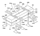
次に、図11に従来の振動ジャイロの別の破砕分解斜視図を示す。図11において、図10に示した振動ジャイロ80と同一又は同等の部分には同じ記号を付し、説明を省略する。
【0010】
図11において、振動ジャイロ90は、振動ジャイロ80の枠体810に代えて、枠体820を有し、更に、図10において図示を省略した基板830と、下蓋840と、下蓋840と同様の構成の図示を省略した上蓋とを有する。
【0011】
枠体820は樹脂からなり、第一の圧電体基板101の一方主面より上側の平面上に上面820a、第二の圧電体基板102の一方主面より下側の平面上に下面820bを有し、更に、枠体820の内側面に設けられた凸部812と、枠体820の上面820a、下面820bに設けられた凹溝813とを有している。凸部812の上面から、支持部材804、805が枠体820に導入され、凸部812の側面から、支持部材806、807が枠体820に導入され、凸部812の側面から、支持部材804、805、806、807の端部805a、807aと、図示を省略した端部804a、806aが導出されている。
【0012】
基板830は、表面にはランド831、832、833、834が形成され、裏面には、図示を省略した振動子100を駆動し、又は、角速度を検出するために必要な電子部品が搭載される。そして、基板830は、凸部812の下面と枠体820の内側面とに係合するように枠体820に固定される。そして、支持部材804、805、806、807の端部804a、805a、806a、807aはランド831、832、833、834に接続される。上蓋及び下蓋840は樹脂からなり、第三の突起部841を有する。そして、上蓋及び下蓋840は、第三の突起部841と枠体820の凹溝813とが係合するように枠体820に固定される。
【0013】
このような構成を有する振動ジャイロ90は、振動子100が枠体820に固定されると同時に、基板830が枠体820に固定され、振動子100と枠体820と基板830とを一体化することができる。そして、更に、上蓋と下蓋840とを設けることにより基板830に搭載された電子部品を密封し、電子部品が外部と電気的に接続しないようにシールドすることができる。
【0014】
【発明が解決しようとする課題】
従来の振動ジャイロ80は、振動子100のノード点N1、N2を挟むように細い支持部材804、805、806、807が設けられ、圧電体基板101、102と同一の厚みを有する枠体810に固定されている。このため、振動子100の振幅が減衰するという問題がなく、また、細い支持部材を用いても振動子100が支持部材804、805、806、807から外れるなどの不具合を生じにくい。
【0015】
しかし、図10に示した従来の振動ジャイロ80においては、枠体810を有する分だけ、部品点数が増加するという問題がある。
【0016】
また、支持部材804、805、806、807をハンダで枠体810に固定した場合、ハンダで固定した端部804a、805a、806a、807aの近傍において、支持部材804、805、806、807と枠体810との間に摩擦が生じ、その摩擦により振動子100の振動が乱れるという問題がある。
【0017】
更に、図11に示した従来の振動ジャイロ90においては、振動子100と基板830とを一体化させる際に、樹脂からなる枠体820を有する分だけ、振動ジャイロ全体としての体積が大きくなってしまうという問題がある。
【0018】
特に、製品の仕様として振動ジャイロ全体の面積が定められている場合には、基板830の面積が制約されるため、基板830の表面及び裏面に振動子100や必要な電子部品を搭載する必要が生じ、振動ジャイロ全体が高背化するという問題が生じる。また、基板830の裏面に電子部品を搭載する場合には、電子部品を密封するために下蓋840を設ける必要が生じ、更に、振動ジャイロ全体が高背化し、部品点数が増加するという問題がある。
【0019】
また、枠体820と支持部材804、805、806、807とを立体的に構成する製造工程は非常に複雑であり、製造に手間がかかるという問題がある。
【0020】
そこで、本発明は、部品点数の削減が図れる振動ジャイロを提供することを目的とする。
【0021】
また、本発明は、小面積化と低背化とが図れる振動ジャイロを提供することを目的とする。
【0022】
また、本発明は、振動ジャイロの部品点数の削減と小型化とにより、低コスト化と小型化とが図れる電子装置を提供することを目的とする。
【0023】
【課題を解決するための手段】
上記目的を達成するために、本発明の振動ジャイロは、基板と、振動子と、前記振動子の両主面におけるそれぞれのノード点付近に固定された4つの支持部材とを有する振動ジャイロであって、前記4つの支持部材は、前記振動子の両主面から前記基板に対して平行な方向に延びる第一の部分と、前記基板に対して直交する方向に延びる第二の部分とを有し、前記4つの支持部材のうち第一の支持部材は、前記振動子の一方主面において一方のノード点付近に固定され、前記4つの支持部材のうち第二の支持部材は、前記振動子の他方主面において前記一方のノード点付近に固定され、前記4つの支持部材のうち第三の支持部材は、前記振動子の一方主面において他方のノード点付近に固定され、前記4つの支持部材のうち第四の支持部材は、前記振動子の他方主面において前記他方のノード点付近に固定され、前記第一の支持部材は、第一の部位が前記一方のノード点から前記基板に平行にかつ前記振動子の長手方向に直交して延び、さらに前記振動子の長手方向と平行しかつ前記振動体の突端側または中央側に向かって屈曲してなり、第二の部位が基板と直交する方向に延び、前記第二の支持部材は、第一の部位が前記一方のノード点から前記基板に平行にかつ前記振動子の長手方向に直交して延び、さらに前記振動子の長手方向と平行しかつ前記第一の支持部材の第一の部位の屈曲の向きと逆向きに屈曲してなり、第二の部位が基板と直交する方向に延び、前記第三の支持部材は、第一の部位が前記他方のノード点から前記基板に平行にかつ前記振動子の長手方向に直交して延び、さらに前記振動子の長手方向と平行しかつ前記振動体の突端側または中央側に向かって屈曲してなり、第二の部位が基板と直交する方向に延び、前記第四の支持部材は、第一の部位が前記他方のノード点から前記基板に平行にかつ前記振動子の長手方向に直交して延び、さらに前記振動子の長手方向と平行しかつ前記第三の支持部材の第一の部位の屈曲の向きと逆向きに屈曲してなり、第二の部位が基板と直交する方向に延び、前記第一の支持部材の第二の部位と、前記第二の支持部材の第二の部位が、前記一方のノード点を挟んで対向するように前記基板と固定され、前記第三の支持部材の第二の部位と、前記第四の支持部材の第二の部位が、前記他方のノード点を挟んで対向するように前記基板と固定されてなることを特徴とする。
【0024】
また、本発明の振動ジャイロは、前記第二の部分が前記振動子に近設され、前記振動子が過大に変位したときは、前記第二の部分が前記振動子の過大な変位を抑制することを特徴とする。
【0025】
また、本発明の振動ジャイロは、前記第二の部分が突起部を有し、前記突起部が前記振動子に近設され、前記振動子が過大に変位したときは、前記突起部が前記振動子の過大な変位を抑制することを特徴とする。
【0026】
また、本発明の振動ジャイロは、前記第二の部分は、前記基板に対して直交する方向に折返す形状を有する屈折部を有することを特徴とする。
【0027】
また、本発明の振動ジャイロは、前記支持部材は、硬弾性材料からなることを特徴とする。
【0028】
また、本発明の振動ジャイロは、前記振動子を振動させるための駆動手段と、前記振動子から発生する出力を検出する検出手段とを有することを特徴とする。
【0029】
また、本発明の振動ジャイロは、前記基板が、前記振動子が搭載される面にのみ電子部品が搭載され、前記振動子と前記電子部品とを覆うようにケースが固着されることを特徴とする。
【0030】
また、本発明の振動ジャイロは、前記基板が端部にスルーホールを有することを特徴とする。
【0031】
また、本発明の電子装置は、前記振動ジャイロを用いたことを特徴とする。
【0032】
このように構成することにより、本発明の振動ジャイロは、振動子の振動が支持部材から漏れにくく、かつ、過大な衝撃が加えられた場合でも圧電体基板が支持部材から外れるという具合を生じにくい。
【0033】
また、本発明の振動ジャイロは、過大な衝撃が加えられた場合でも、支持部材が塑性変形しにくい。
【0034】
また、本発明の振動ジャイロは、枠体を有していないため部品点数の削減を図ることができる。
【0035】
また、本発明の振動ジャイロは、第二の部分に設けられた屈折部の長さを調節することにより支持部材の剛性を調整することができるため、振動子の上面に設けられた支持部材の剛性と、振動子の下面に設けられた支持部材の剛性とを等しくすることができ、振動子が自由に振動でき、角速度を正確に検出できる。
【0036】
また、本発明の振動ジャイロは、ケースを基板に固定し、基板の端部にスルーホールを設けることにより、表面実装部品として用いることができる。
【0037】
また、本発明の電子装置は、振動ジャイロの部品点数の削減と小型化とにより、低コスト化と小型化とを図ることができる。
【0038】
【発明の実施の形態】
図1に本発明の振動ジャイロの一実施例の斜視図を示し、図2に平面図及び正面図及び底面図を示す。図1、2において、図10、11に示した振動ジャイロ80、90と同一又は同等の部分には同じ記号を付し、説明を省略する。
【0039】
図1、2において、振動ジャイロ10は、振動子100と図示を省略した基板と支持部材104、105、106、107とを有する。支持部材104、105、106、107はそれぞれ金属などの硬弾性材料からなり、圧電体基板101、102の一方主面が形成された平面において、圧電体基板101、102の一方主面から振動子100の幅方向に離れた後、屈折して振動子100に接近する第一の部分104a、105a、106a、107aと、振動子100の近傍から振動子100の厚み方向に延びる第二の部分104b、105b、106b、107bとを有する。そして、第二の部分104b、105b、106b、107bの端部104c、105c、106c、107cは基板に固定される。
【0040】
このような構成を有する振動ジャイロ10は、振動子100のノード点N1を第一の部分104a、106aでサンドイッチ状に支持し、ノード点N2を第一の部分105a、107aでサンドイッチ状に支持している。このように、圧電体基板101及び圧電体基板102の一方主面で、振動子100をサンドイッチ状に支持することにより、枠体や太い支持部材を用いなくても、振動ジャイロ10に過大な衝撃が加えられた場合でも振動子100が支持部材104、105、106、107から外れるなどの不具合を生じにくい。
【0041】
また、振動ジャイロ10の第一の部分104a、105a、106a、107aは、圧電体基板101、102の一方主面と平行な平面において、振動子100の幅方向に延びた後、振動子100の長手方向に、くの字型に屈折する形状を有し、振動子100の幅方向の振動をダンピングすることなく振動させる柔構造となる。したがって、圧電体基板101、102の幅方向の振動が、支持部材104、105、106、107から漏れにくく、振動子100の振幅が減衰しにくい。
【0042】
また、振動ジャイロ10は、第二の部分104b、105bを振動子100に近接させるために、第一の部分104a、105aが振動子100の幅方向に延びた後、Uの字型に折り返す形状を有している。そして、振動ジャイロ10に振動子100の幅方向の過大な衝撃が与えられた場合には、振動子100が第二の部分104b、105bに衝突する。したがって、振動子100が過大に変位し、支持部材104、105、106、107が塑性変形することを防ぐことができる。
【0043】
また、振動ジャイロ10は、枠体を有していないため部品点数の削減を図ることができる。
【0044】
次に、図3に本発明の振動ジャイロの支持部材の別の実施例の斜視図を示す。図3においては、図1、2に示した振動ジャイロの支持部材105に対応する支持部材135、及び、支持部材106に対応する支持部材136のみを図示する。
【0045】
図3において、支持部材135の第二の部分は、振動子100の厚み方向に折返す形状を有する屈折部135b′、135b′′を有し、図示を省略した支持部材104に対応する支持部材134も同様の屈折部134b′、134b′′を有する。また、支持部材136の第二の部分は、振動子100の厚み方向に折返す形状を有する屈折部136b′、136b′′を有し、図示を省略した支持部材107に対応する支持部材137も同様の屈折部137b′、137b′′を有する。
【0046】
一般に、支持部材を用いて振動子を基板に固定する場合、基板から振動子までの距離が長くなるほど、振動子の厚み方向に関する剛性が小さくなる。したがって、振動子の上面に設けられた支持部材の方が、振動子の下面に設けられた支持部材よりも剛性が小さくなる。このように、基板からの距離によって、支持部材の剛性が異なるときは、振動子の上面と下面とで異なった状態で支持がされることになり、振動子の厚み方向に関する自由な振動が妨げられ、角速度を正確に検出できなくなる。
【0047】
図3に示した構成を有する振動ジャイロにおいては、振動子100の厚み方向に関する剛性が同一になるように、屈折部134b′、134b′′の長さと、屈折部136b′、136b′′の長さとを調整することができ、屈折部135b′、135b′′の長さと、屈折部137b′、137b′′の長さとを調整することができる。したがって、屈折部を適宜調整することにより、振動子100の上面に設けられた支持部材134、135と、振動子100の下面に設けられた支持部材136、137とが、振動子100の厚み方向に関して同一の剛性になる。
【0048】
なお、振動ジャイロの支持部材136、137にのみ、屈折部を設けても同様の効果を奏する。
【0049】
次に、図4に本発明の振動ジャイロの別の実施例の平面図及び正面図及び底面図を示す。図4において、図1、2に示した振動ジャイロ10と同一又は同等の部分には同じ記号を付し、説明を省略する。
【0050】
図4において、振動ジャイロ11は、振動ジャイロ10の支持部材104、105のに代えて、支持部材114、115を有する。支持部材114、115は、第二の部分114b、115bに突起部104d、105dを有する。突起部104d、105dは、振動子100の長手方向に対して僅かな傾斜角度を有し、振動子100に接近している。
【0051】
このような構成を有する振動ジャイロ11は、突起部104d、105dが、振動子100に近接するように設けられ、振動子100に過大な衝撃が与えられたときは、突起部104d、105dが振動子100に衝突し、振動子100の過大な変位を抑制することができる。また、振動ジャイロ11は、突起部104d、105dの傾斜角度を調節することにより、振動子100と支持部材114、115との間隔を微調整することが可能となる。なお、支持部材114、115の一方にのみ、突起部を設けても同様の効果を奏する。
【0052】
次に、図5に、本発明の振動ジャイロの支持部材の更に別の実施例の斜視図を示す。図5においては、図1、2に示した振動ジャイロの支持部材104に対応する支持部材124のみを図示する。
【0053】
図5において、支持部材124は、振動子100に近接していない第二の部分124bに、突起部124dを有し、図示を省略した支持部材105に対応する支持部材125も同様の突起部125dを有する。突起部124d、125dは、突起部104d、105dと同様に、振動子100の長手方向に対して僅かな傾斜角度を有し、振動子100に接近している。
【0054】
このように、支持部材124が、突起部124dを有するときは、第二の部分124bを振動子100に近接させず、突起部124dのみを振動子100に近接させてもよい。なお、支持部材125に突起部125dを設けた場合も、同様の効果を奏する。
【0055】
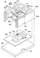
次に、図6に本発明の振動ジャイロの更に別の実施例の斜視図を示す。図6において、図1、2に示した振動ジャイロ10と同一又は同等の部分には同じ記号を付し、説明を省略する。
【0056】
図6において、振動ジャイロ60は、図1において図示を省略した基板20と、電子部品30と、ケース40とを有する。基板20は、端部にスルーホール21を有し、表面のみに振動子100及び電子部品30が搭載されている。ここで、電子部品30は、振動子100を駆動し、又は、角速度を検出するために必要な部品である。そして、ケース40は、振動子100と電子部品30とを包むように、基板20の表面に固着される。
【0057】
このような構成を有する振動ジャイロ60は、上蓋と下蓋と枠体とを用いずに、支持部材104、105、106、107で振動子100を基板20に固定し一体化すると同時に、基板20とケース40とで、電子部品30を密封し、電子部品30が外部と電気的に接続しないようにシールドすることができる。そして、上蓋と下蓋と枠体とを有しない分だけ、振動ジャイロ60全体としての体積を小さくし、低背化を実現し、部品点数を削減することができる。
【0058】
特に、基板20には表面のみに振動子100及び電子部品30が搭載され、基板20の裏面は電子部品30と電気的に接続していない。したがって、振動ジャイロ60は、基板20の端部にスルーホール21を設けることにより、外部の回路パターンにそのまま実装可能な表面実装部品として用いることができる。
【0059】
更に、振動ジャイロ60のケース40が金属ケースである場合には、樹脂ケースに比べて肉厚が薄いので、その分だけ振動ジャイロ60全体としての体積を小さくすることができると同時に、外部の電磁波から電子部品30を保護することができる。そして、ケース40の肉厚を薄くすることにより、基板20上におけるケースの占める面積が小さくなるため、基板20上の部品搭載面積及びランド面積を大きくすることができる。
【0060】
次に、図7に、本発明の振動ジャイロのブロック図を示す。図7は、図6に示した電子部品30により構成された本発明の振動ジャイロ60のブロック図であり、駆動手段である発振回路601と、検出手段である検出回路602とを有する。発振回路601は、第一のチャージアンプ601aと、第二のチャージアンプ601bと、加算回路601cと、AGC回路601dと、位相補正回路601eとを有し、検出回路602は、第一のチャージアンプ601aと、第二のチャージアンプ601bと、差動回路602aと、検波回路602bと、平滑回路602cと、増幅回路602dとを有している。
【0061】
ここで、振動子100の第一の検出電極101aは第一のチャージアンプ601aに接続され、第二の検出電極101bは第二のチャージアンプ601bに接続されている。第一のチャージアンプ601a、第二のチャージアンプ601bは、加算回路601cと差動回路602aとにそれぞれ接続されている。加算回路601cはAGC回路601dに接続され、AGC回路601dは位相補正回路601eに接続され、位相補正回路601eは検波回路602bと、駆動電極102aとに接続されている。そして、差動回路602aは検波回路602bに接続され、検波回路602bは平滑回路602cに接続され、平滑回路602cは増幅回路602dに接続されている。
【0062】
このように構成された本発明の振動ジャイロ60において、第一のチャージアンプ601aは第一の検出電極101aの発生電荷を電圧に変換して加算回路601cと差動回路602aとに出力し、第二のチャージアンプ601bは第二の検出電極101bの発生電荷を電圧に変換して加算回路601cと差動回路602aとに出力する。加算回路601cは、入力された信号を加算してAGC回路601dに出力し、AGC回路601dは、入力された信号の振幅が一定となるように増幅して、位相補正回路601eに出力し、位相補正回路601eは入力された信号の位相を補正して駆動電極102aに駆動信号を印可する。
【0063】
一方、差動回路602aは、入力された信号を減算して検波回路602bに出力し、検波回路602bは差動回路602aから入力された信号を位相補正回路601eから入力された信号により検波して平滑回路602cに出力し、平滑回路602cは入力された信号を平滑して増幅回路602dに出力し、増幅回路602dは入力された信号を直流増幅して外部に出力する。
【0064】
このような構成の振動ジャイロ60は、駆動電極102aに駆動信号を印可することにより、振動子100が厚み方向に、最低次のモードの節がノード点N1、N2となる長手方向両端自由たわみ振動をする。そして、振動子100に、長手方向を軸とする角速度が与えられた場合には、コリオリ力により幅方向に屈曲変位が発生するため、第一の検出電極101a及び第二の検出電極101bの信号の差から角速度を検出することができる。また、第一の検出電極101a及び第二の検出電極101bの信号の和から、コリオリ力の影響を受けない、振動子100の厚み方向の屈曲変位に相当する信号を検出できる。
【0065】
このように、本発明の振動ジャイロ60は、角速度の検知に必要な発振回路601と検出回路602とを内部に備えているため、一体化された振動ジャイロユニットを構成することができる。
【0066】
次に、図8に本発明の振動ジャイロの更に別の実施例を示す。図8において、図7に示した振動ジャイロ60と同一又は同等の部分には同じ記号を付し、説明を省略する。
【0067】
図8において、本発明の振動ジャイロ61は、図7に示した振動ジャイロ60の発振回路601、検出回路602に代えて、発振回路611、検出回路612を有する。発振回路611、検出回路612は、図8に示した第一のチャージアンプ601a、第二のチャージアンプ601bに代えて、抵抗611a、611bと第一のバッファ回路611cと第二のバッファ回路611dとを有する点のみが、発振回路601、検出回路602と異なる。
【0068】
このように、振動ジャイロは61は、第一の検出電極101aに抵抗611aと第一のバッファ回路611cとが接続され、第二の検出電極101bに抵抗611bと第二のバッファ回路611dとが接続されている。そして、第一のバッファ回路611c、第二のバッファ回路611dは、加算回路601cと差動回路602aとに接続されている。ここで、第一のバッファ回路611cは第一の検出電極101aの電圧を加算回路601cと差動回路602aとに出力するためのものであり、第二のバッファ回路611dは第二の検出電極101bの電圧を加算回路601cと差動回路602aとに出力するためのものであり、抵抗611a、611bは、第一の検出電極101a、第二の検出電極101bのインピーダンスを調整するためのものである。
【0069】
このような構成を有する本発明の振動ジャイロ61も、図7に示した振動ジャイロは60と同様の効果を奏する。
【0070】
次に、図9に本発明の振動ジャイロを用いた電子装置の一実施例を示す。図9は本発明の電子装置であるビデオカメラに用いられる手ぶれ防止回路の一実施例を示すブロック図である。手ぶれ防止回路70は、本発明の振動ジャイロ10と積分回路701とサーボ回路702と電流ドライバ703とアクチュエータ704と位置検出センサ705とを有する。手ぶれ防止回路70は、振動ジャイロ10と、積分回路701と、サーボ回路702と、電流ドライバ703と、アクチュエータ704とが直列に接続され、アクチュエータ704の出力が位置検出センサ705を介してサーボ回路702に帰還されている。
【0071】
このように構成された手ぶれ防止回路70においては、ビデオカメラに与えられた手ぶれのうち、角速度信号のみが振動ジャイロ10から積分回路701に入力され、積分回路701は角速度信号を積分してビデオカメラの振れ角に変換してサーボ回路702に出力し、サーボ回路702は、積分回路701と位置検出センサ705とから入力された振れ角の信号を用いて現在値と目標値との差を演算して電流ドライバ703に出力し、電流ドライバ703は入力された信号に応じた電流をアクチュエータ704に出力し、アクチュエータ704はビデオカメラの光学系を機械的に駆動する。そして、位置検出センサ705は光学系が駆動した振れ角をサーボ回路702に出力する。
【0072】
このような構成を有する手ぶれ防止回路70を有するビデオカメラは、角速度を正確に検出できる振動ジャイロ10を用いているので、ビデオカメラに与えられる手ぶれの影響を的確に除去できる。
【0073】
以上、ビデオカメラを用いて本発明の電子装置を説明したが、本発明の電子装置は、このような構成のビデオカメラに限られるものではないことは言うまでもない。
【0074】
【発明の効果】
本発明の振動ジャイロは、振動子をノード点N1、N2の上下からサンドイッチ状に支持することにより、振動子の振動が支持部材から漏れにくく、かつ、過大な衝撃が加えられた場合でも振動子が支持部材から外れるという具合を生じにくい。
【0075】
また、本発明の振動ジャイロは、第二の部分が振動子に近接するように設けられているため、過大な衝撃が加えられた場合でも、支持部材が塑性変形しにくい。
【0076】
また、本発明の振動ジャイロは、枠体を有していないため部品点数の削減を図ることができる。
【0077】
また、本発明の振動ジャイロは、第二の部分に設けられた屈折部の長さを調節することにより支持部材の剛性を調整することができるため、振動子の上面に設けられた支持部材の剛性と、振動子の下面に設けられた支持部材の剛性とを等しくすることができ、振動子が自由に振動でき、角速度を正確に検出できる。
【0078】
また、本発明の振動ジャイロは、上蓋と下蓋と枠体とを用いずに、振動子を基板に固定し一体化することができる。したがって、上蓋と下蓋と枠体とを有しない分だけ、振動ジャイロ全体として体積を小さくし、低背化を実現し、部品点数を削減することができる。
【0079】
また、本発明の振動ジャイロは、基板の裏面が電子部品と電気的に接続していないため、ケースを基板に固定し、基板の端部にスルーホールを設けることにより、表面実装部品として用いることができる。
【0080】
また、本発明の振動ジャイロは、金属からなるケースを有するため、体積を小さくすることができると同時に、外部の電磁波から電子部品を保護することができる。
【0081】
また、本発明の振動ジャイロは、枠体を有していない分だけ体積が小さくなるため、基板上の部品搭載面積及びランド面積を大きくすることができる。
【0082】
また、本発明の電子装置は、振動ジャイロの部品点数の削減と小型化とにより、低コスト化と小型化とを図ることができる。
【図面の簡単な説明】
【図1】本発明の振動ジャイロの一実施例を示す斜視図である。
【図2】図1の振動ジャイロの平面図及び正面図及び底面図である。
【図3】図1の振動ジャイロの支持部材の別の実施例を示す斜視図である。
【図4】本発明の振動ジャイロの別の実施例を示す平面図及び正面図及び底面図である。
【図5】図4の振動ジャイロの支持部材の別の実施例を示す斜視図である。
【図6】本発明の振動ジャイロの更に別の実施例を示す斜視図である。
【図7】図6の振動ジャイロの実施例を示すブロック図である。
【図8】本発明の振動ジャイロの更に別の実施例を示すブロック図である。
【図9】本発明の電子装置に用いられる手ぶれ防止回路の一実施例を示すブロック図である。
【図10】従来の振動ジャイロを示す破砕斜視図である。
【図11】従来の別の振動ジャイロを示す破砕分解斜視図である。
【符号の説明】
10、11、60、61…振動ジャイロ
100…振動子
70…手ぶれ防止回路
N1、N2…ノード点
101…第一の圧電体
102…第二の圧電体
103…中間電極
104、105、106、107、114、115、124、135、136…支持部材
101a…第一の検出電極
101b…第二の検出電極
102a…駆動電極
20…基板
30…電子部品
40…ケース[0001]
BACKGROUND OF THE INVENTION
The present invention relates to a vibration gyro and an electronic device using the vibration gyro, and more particularly to a vibration gyro used for a video camera with a camera shake prevention function, a car navigation system, a pointing device, and the like, and an electronic device using the vibration gyro.
[0002]
[Prior art]
FIG. 10 shows a fragmented perspective view of a conventional vibrating gyroscope. The basic concept of the vibrating
[0003]
In FIG. 10, the
[0004]
The
[0005]
By the way, in general, in a vibrating gyroscope, it is necessary to make the support member thick so as not to cause a problem such that the vibrator is detached from the support member even when an excessive impact is applied to the vibrating gyroscope. However, when a thick support member is used, there is a problem that the vibration of the vibrator leaks from the support member and the amplitude of the vibrator becomes small.
[0006]
The
[0007]
The
[0008]
Further, since the
[0009]
Next, FIG. 11 shows another crushing exploded perspective view of a conventional vibrating gyroscope. In FIG. 11, parts that are the same as or equivalent to those of the
[0010]
In FIG. 11, the
[0011]
The
[0012]
The
[0013]
In the vibrating
[0014]
[Problems to be solved by the invention]
A conventional
[0015]
However, the conventional vibrating
[0016]
When the
[0017]
Furthermore, in the conventional vibrating
[0018]
In particular, when the area of the entire vibrating gyroscope is determined as a product specification, the area of the
[0019]
Further, the manufacturing process for constructing the
[0020]
Therefore, an object of the present invention is to provide a vibration gyro capable of reducing the number of parts.
[0021]
Another object of the present invention is to provide a vibrating gyroscope that can be reduced in area and height.
[0022]
It is another object of the present invention to provide an electronic device that can be reduced in cost and size by reducing the number of parts and size of a vibrating gyroscope.
[0023]
[Means for Solving the Problems]
In order to achieve the above object, a vibration gyro according to the present invention includes a substrate, a vibrator, and both main surfaces of the vibrator. Each in Fixed near the node point of Four A vibrating gyroscope having a support member, Four The support member has a first portion extending in a direction parallel to the substrate from both main surfaces of the vibrator, and a second portion extending in a direction orthogonal to the substrate, The first support member of the four support members is fixed near one node point on one main surface of the vibrator, Of the four support members, a second support member is fixed in the vicinity of the one node point on the other principal surface of the vibrator, and among the four support members, a third support member is formed of the vibrator. On one main surface, it is fixed near the other node point, Of the four support members, a fourth support member is fixed near the other node point on the other main surface of the vibrator, and the first support member has a first part at the one node point. Extending in parallel to the substrate and perpendicular to the longitudinal direction of the vibrator, and further bent parallel to the longitudinal direction of the vibrator and toward the projecting end side or the center side of the vibrator. The part extends in a direction perpendicular to the substrate, and the second support member includes a first part extending from the one node point in parallel to the substrate and perpendicular to the longitudinal direction of the vibrator, and the vibration Parallel to the longitudinal direction of the child and bent in the direction opposite to the bending direction of the first part of the first support member, the second part extending in a direction perpendicular to the substrate, and the third support The member has a first portion from the other node point to the substrate. Extending in a row and perpendicular to the longitudinal direction of the vibrator, and further bent parallel to the longitudinal direction of the vibrator and toward the projecting end side or the center side of the vibrator, and the second portion is a substrate and The fourth support member extends in a direction orthogonal to the first portion, the first portion extends from the other node point in parallel to the substrate and orthogonal to the longitudinal direction of the vibrator, and further, the longitudinal direction of the vibrator And the second portion extends in a direction perpendicular to the substrate, and is bent in a direction opposite to the bending direction of the first portion of the third support member. And the second part of the second support member are fixed to the substrate so as to face each other across the one node point, the second part of the third support member, and the second part The second parts of the four support members are opposed to each other across the other node point. Formed by fixed and serial board It is characterized by that.
[0024]
Further, in the vibration gyro according to the present invention, when the second part is disposed close to the vibrator and the vibrator is excessively displaced, the second part suppresses excessive displacement of the vibrator. It is characterized by that.
[0025]
In the vibration gyro of the present invention, the second portion has a protrusion, the protrusion is close to the vibrator, and the protrusion is vibrated when the vibrator is excessively displaced. It is characterized by suppressing excessive displacement of the child.
[0026]
The vibrating gyroscope according to the present invention is characterized in that the second portion has a refracting portion having a shape that is folded in a direction orthogonal to the substrate.
[0027]
The vibrating gyroscope according to the present invention is characterized in that the support member is made of a hard elastic material.
[0028]
The vibrating gyroscope according to the present invention includes a driving unit for vibrating the vibrator and a detecting unit for detecting an output generated from the vibrator.
[0029]
The vibration gyro of the present invention is characterized in that an electronic component is mounted only on a surface of the substrate on which the vibrator is mounted, and a case is fixed so as to cover the vibrator and the electronic component. To do.
[0030]
The vibrating gyroscope according to the present invention is characterized in that the substrate has a through hole at an end.
[0031]
Also, an electronic device according to the present invention is characterized by using the vibration gyro.
[0032]
With this configuration, the vibratory gyroscope according to the present invention is unlikely to cause the vibration of the vibrator to leak from the support member and to cause the piezoelectric substrate to be detached from the support member even when an excessive impact is applied. .
[0033]
Further, in the vibration gyro according to the present invention, even when an excessive impact is applied, the support member is difficult to be plastically deformed.
[0034]
Moreover, since the vibrating gyroscope of the present invention does not have a frame, the number of parts can be reduced.
[0035]
In addition, since the vibration gyro of the present invention can adjust the rigidity of the support member by adjusting the length of the refracting portion provided in the second portion, the vibration gyro of the support member provided on the upper surface of the vibrator The rigidity and the rigidity of the support member provided on the lower surface of the vibrator can be made equal, so that the vibrator can vibrate freely and the angular velocity can be accurately detected.
[0036]
The vibrating gyroscope of the present invention can be used as a surface mount component by fixing the case to the substrate and providing a through hole at the end of the substrate.
[0037]
In addition, the electronic device of the present invention can achieve cost reduction and size reduction by reducing the number of parts and size of the vibration gyro.
[0038]
DETAILED DESCRIPTION OF THE INVENTION
FIG. 1 shows a perspective view of an embodiment of a vibrating gyroscope according to the present invention, and FIG. 2 shows a plan view, a front view, and a bottom view. 1 and 2, the same or equivalent parts as those of the vibrating
[0039]
1 and 2, the vibrating
[0040]
In the vibrating
[0041]
The
[0042]
In addition, the vibrating
[0043]
Moreover, since the
[0044]
Next, FIG. 3 shows a perspective view of another embodiment of the supporting member of the vibrating gyroscope of the present invention. 3, only the
[0045]
In FIG. 3, the second part of the
[0046]
Generally, when a vibrator is fixed to a substrate using a support member, the rigidity in the thickness direction of the vibrator decreases as the distance from the substrate to the vibrator increases. Therefore, the support member provided on the upper surface of the vibrator is less rigid than the support member provided on the lower surface of the vibrator. Thus, when the rigidity of the support member varies depending on the distance from the substrate, the upper surface and the lower surface of the vibrator are supported in different states, and free vibration in the thickness direction of the vibrator is hindered. Therefore, the angular velocity cannot be detected accurately.
[0047]
In the vibrating gyroscope having the configuration shown in FIG. 3, the lengths of the refracting portions 134b ′ and 134b ″ and the lengths of the refracting
[0048]
It should be noted that the same effect can be obtained by providing a refracting portion only on the
[0049]
Next, FIG. 4 shows a plan view, a front view, and a bottom view of another embodiment of the vibrating gyroscope of the present invention. In FIG. 4, the same or equivalent parts as those of the vibrating
[0050]
In FIG. 4, the
[0051]
The
[0052]
Next, FIG. 5 shows a perspective view of still another embodiment of the supporting member of the vibrating gyroscope of the present invention. In FIG. 5, only the
[0053]
In FIG. 5, the
[0054]
As described above, when the
[0055]
Next, FIG. 6 shows a perspective view of still another embodiment of the vibrating gyroscope of the present invention. In FIG. 6, the same or equivalent parts as those of the vibrating
[0056]
In FIG. 6, the vibrating
[0057]
The
[0058]
In particular, the
[0059]
Further, when the
[0060]
Next, FIG. 7 shows a block diagram of the vibrating gyroscope of the present invention. FIG. 7 is a block diagram of the vibrating
[0061]
Here, the
[0062]
In the vibrating
[0063]
On the other hand, the
[0064]
In the
[0065]
Thus, since the
[0066]
Next, FIG. 8 shows still another embodiment of the vibrating gyroscope of the present invention. In FIG. 8, the same or equivalent parts as those of the vibrating
[0067]
In FIG. 8, the
[0068]
As described above, the vibrating
[0069]
The
[0070]
Next, FIG. 9 shows an embodiment of an electronic device using the vibrating gyroscope of the present invention. FIG. 9 is a block diagram showing an embodiment of a camera shake prevention circuit used in a video camera which is an electronic apparatus according to the present invention. The camera
[0071]
In the camera
[0072]
Since the video camera having the camera
[0073]
The electronic device of the present invention has been described above using a video camera, but it goes without saying that the electronic device of the present invention is not limited to the video camera having such a configuration.
[0074]
【The invention's effect】
The vibration gyro of the present invention supports the vibrator in a sandwich shape from above and below the node points N1 and N2, so that the vibration of the vibrator is difficult to leak from the support member and even when an excessive impact is applied. Is unlikely to come off the support member.
[0075]
In addition, since the vibration gyro of the present invention is provided so that the second portion is close to the vibrator, the support member is not easily plastically deformed even when an excessive impact is applied.
[0076]
Moreover, since the vibrating gyroscope of the present invention does not have a frame, the number of parts can be reduced.
[0077]
In addition, since the vibration gyro of the present invention can adjust the rigidity of the support member by adjusting the length of the refracting portion provided in the second portion, the vibration gyro of the support member provided on the upper surface of the vibrator The rigidity and the rigidity of the support member provided on the lower surface of the vibrator can be made equal, so that the vibrator can vibrate freely and the angular velocity can be accurately detected.
[0078]
The vibrating gyroscope according to the present invention can be integrated with the vibrator fixed to the substrate without using the upper lid, the lower lid, and the frame. Therefore, the volume of the entire vibrating gyroscope can be reduced by the amount that does not include the upper lid, the lower lid, and the frame body, the height can be reduced, and the number of parts can be reduced.
[0079]
Moreover, since the back surface of the substrate is not electrically connected to the electronic component, the vibration gyro of the present invention is used as a surface mount component by fixing the case to the substrate and providing a through hole at the end of the substrate. Can do.
[0080]
In addition, since the vibrating gyroscope of the present invention has a case made of metal, the volume can be reduced, and at the same time, electronic components can be protected from external electromagnetic waves.
[0081]
In addition, since the volume of the vibrating gyroscope of the present invention is reduced by the amount not having the frame, the component mounting area and land area on the board can be increased.
[0082]
In addition, the electronic device of the present invention can achieve cost reduction and size reduction by reducing the number of parts and size of the vibration gyro.
[Brief description of the drawings]
FIG. 1 is a perspective view showing an embodiment of a vibrating gyroscope according to the present invention.
2 is a plan view, a front view, and a bottom view of the vibrating gyroscope of FIG. 1; FIG.
3 is a perspective view showing another embodiment of the support member of the vibrating gyroscope of FIG. 1. FIG.
FIG. 4 is a plan view, a front view, and a bottom view showing another embodiment of the vibrating gyroscope of the present invention.
5 is a perspective view showing another embodiment of the support member of the vibrating gyroscope of FIG. 4. FIG.
FIG. 6 is a perspective view showing still another embodiment of the vibrating gyroscope according to the present invention.
7 is a block diagram showing an embodiment of the vibration gyro shown in FIG. 6;
FIG. 8 is a block diagram showing still another embodiment of the vibration gyro according to the present invention.
FIG. 9 is a block diagram showing one embodiment of a camera shake prevention circuit used in the electronic apparatus of the present invention.
FIG. 10 is a fragmentary perspective view showing a conventional vibrating gyroscope.
FIG. 11 is an exploded perspective view showing another conventional vibrating gyroscope.
[Explanation of symbols]
10, 11, 60, 61 ... vibrating gyro
100 ... vibrator
70 ... Shake prevention circuit
N1, N2 ... Node points
101: First piezoelectric body
102 ... Second piezoelectric body
103 ... Intermediate electrode
104, 105, 106, 107, 114, 115, 124, 135, 136 ... support members
101a ... first detection electrode
101b ... second detection electrode
102a ... Driving electrode
20 ... Board
30 ... Electronic components
40 ... Case
Claims (4)
前記4つの支持部材は、前記振動子の両主面から前記基板に対して平行な方向に延びる第一の部分と、前記基板に対して直交する方向に延びる第二の部分とを有し、
前記4つの支持部材のうち第一の支持部材は、前記振動子の一方主面において一方のノード点付近に固定され、
前記4つの支持部材のうち第二の支持部材は、前記振動子の他方主面において前記一方のノード点付近に固定され、
前記4つの支持部材のうち第三の支持部材は、前記振動子の一方主面において他方のノード点付近に固定され、
前記4つの支持部材のうち第四の支持部材は、前記振動子の他方主面において前記他方のノード点付近に固定され、
前記第一の支持部材は、第一の部位が前記一方のノード点から前記基板に平行にかつ前記振動子の長手方向に直交して延び、さらに前記振動子の長手方向と平行しかつ前記振動体の突端側または中央側に向かって屈曲してなり、第二の部位が基板と直交する方向に延び、
前記第二の支持部材は、第一の部位が前記一方のノード点から前記基板に平行にかつ前記振動子の長手方向に直交して延び、さらに前記振動子の長手方向と平行しかつ前記第一の支持部材の第一の部位の屈曲の向きと逆向きに屈曲してなり、第二の部位が基板と直交する方向に延び、
前記第三の支持部材は、第一の部位が前記他方のノード点から前記基板に平行にかつ前記振動子の長手方向に直交して延び、さらに前記振動子の長手方向と平行しかつ前記振動体の突端側または中央側に向かって屈曲してなり、第二の部位が基板と直交する方向に延び、
前記第四の支持部材は、第一の部位が前記他方のノード点から前記基板に平行にかつ前記振動子の長手方向に直交して延び、さらに前記振動子の長手方向と平行しかつ前記第三の支持部材の第一の部位の屈曲の向きと逆向きに屈曲してなり、第二の部位が基板と直交する方向に延び、
前記第一の支持部材の第二の部位と、前記第二の支持部材の第二の部位が、前記一方のノード点を挟んで対向するように前記基板と固定され、
前記第三の支持部材の第二の部位と、前記第四の支持部材の第二の部位が、前記他方のノード点を挟んで対向するように前記基板と固定されてなる、
振動ジャイロ。 A vibrating gyroscope having a substrate, a vibrator, and four support members fixed near respective node points on both principal surfaces of the vibrator,
The four support members include a first portion extending in a direction parallel to the substrate from both principal surfaces of the vibrator, and a second portion extending in a direction orthogonal to the substrate,
The first support member of the four support members is fixed near one node point on one main surface of the vibrator,
Of the four support members, a second support member is fixed near the one node point on the other main surface of the vibrator,
Of the four support members, the third support member is fixed near the other node point on one main surface of the vibrator,
A fourth support member of the four support members is fixed near the other node point on the other main surface of the vibrator,
The first support member has a first portion extending from the one node point parallel to the substrate and perpendicular to the longitudinal direction of the vibrator, and further parallel to the longitudinal direction of the vibrator and the vibration. It is bent toward the tip side or the center side of the body, and the second part extends in a direction perpendicular to the substrate,
The second support member has a first portion extending from the one node point parallel to the substrate and perpendicular to the longitudinal direction of the vibrator, further parallel to the longitudinal direction of the vibrator and the first The first member of the first support member is bent in a direction opposite to the bending direction of the first member, and the second member extends in a direction perpendicular to the substrate,
The third support member has a first portion extending from the other node point parallel to the substrate and perpendicular to the longitudinal direction of the vibrator, and further parallel to the longitudinal direction of the vibrator and the vibration. It is bent toward the tip side or the center side of the body, and the second part extends in a direction perpendicular to the substrate,
The fourth support member has a first portion extending from the other node point parallel to the substrate and perpendicular to the longitudinal direction of the vibrator, further parallel to the longitudinal direction of the vibrator and the first The first support member is bent in the direction opposite to the bending direction of the first part, and the second part extends in a direction perpendicular to the substrate,
The second part of the first support member and the second part of the second support member are fixed to the substrate so as to face each other across the one node point,
The second portion of the third support member and the second portion of the fourth support member are fixed to the substrate so as to face each other across the other node point.
Vibration gyro.
Priority Applications (5)
| Application Number | Priority Date | Filing Date | Title |
|---|---|---|---|
| JP2000036886A JP3674440B2 (en) | 2000-02-15 | 2000-02-15 | Vibrating gyro |
| US09/779,264 US6532816B2 (en) | 2000-02-15 | 2001-02-08 | Vibrating gyroscope and electronic apparatus incorporating the same |
| EP01103086A EP1126241B1 (en) | 2000-02-15 | 2001-02-09 | Vibrating gyroscope and electronic apparatus incorporating the same |
| DE60114261T DE60114261D1 (en) | 2000-02-15 | 2001-02-09 | Vibratory gyro and electronic device with such a gyroscope |
| KR10-2001-0006961A KR100406126B1 (en) | 2000-02-15 | 2001-02-13 | Vibrating gyroscope and electronic apparatus incorporating the same |
Applications Claiming Priority (1)
| Application Number | Priority Date | Filing Date | Title |
|---|---|---|---|
| JP2000036886A JP3674440B2 (en) | 2000-02-15 | 2000-02-15 | Vibrating gyro |
Publications (2)
| Publication Number | Publication Date |
|---|---|
| JP2001227953A JP2001227953A (en) | 2001-08-24 |
| JP3674440B2 true JP3674440B2 (en) | 2005-07-20 |
Family
ID=18560860
Family Applications (1)
| Application Number | Title | Priority Date | Filing Date |
|---|---|---|---|
| JP2000036886A Expired - Lifetime JP3674440B2 (en) | 2000-02-15 | 2000-02-15 | Vibrating gyro |
Country Status (5)
| Country | Link |
|---|---|
| US (1) | US6532816B2 (en) |
| EP (1) | EP1126241B1 (en) |
| JP (1) | JP3674440B2 (en) |
| KR (1) | KR100406126B1 (en) |
| DE (1) | DE60114261D1 (en) |
Families Citing this family (13)
| Publication number | Priority date | Publication date | Assignee | Title |
|---|---|---|---|---|
| JP3613117B2 (en) * | 2000-02-23 | 2005-01-26 | 株式会社村田製作所 | Vibrator, vibratory gyro using the vibrator, and electronic device using the vibrator |
| JP2002228449A (en) * | 2001-01-29 | 2002-08-14 | Murata Mfg Co Ltd | Production method of oscillator gyro |
| JP2002250630A (en) * | 2001-02-26 | 2002-09-06 | Murata Mfg Co Ltd | Oscillator support structure and oscillation gyro using structure, and electronic device using the gyro |
| JP3687609B2 (en) * | 2001-04-19 | 2005-08-24 | 株式会社村田製作所 | Vibrating gyro and electronic device using the same |
| JP3741041B2 (en) * | 2001-05-09 | 2006-02-01 | 株式会社村田製作所 | Vibrating gyro and electronic device using the same |
| JP3698094B2 (en) * | 2001-11-29 | 2005-09-21 | 株式会社村田製作所 | Vibrating gyro and electronic device using the same |
| JP3687619B2 (en) | 2002-03-25 | 2005-08-24 | 株式会社村田製作所 | Vibrating gyro and electronic device using the same |
| JP4497345B2 (en) | 2003-02-12 | 2010-07-07 | 株式会社村田製作所 | Support structure for vibrator and method for manufacturing the support structure |
| JP2005114631A (en) * | 2003-10-09 | 2005-04-28 | Sony Corp | Angular velocity sensor |
| JP2006029901A (en) * | 2004-07-14 | 2006-02-02 | Sony Corp | Driver circuity of oscillating gyroscope |
| KR100828184B1 (en) * | 2006-10-19 | 2008-05-08 | 한국과학기술원 | mechanical variable gain amplifier |
| JP5845672B2 (en) | 2011-07-13 | 2016-01-20 | セイコーエプソン株式会社 | Sensor devices and electronics |
| DE112018004640T5 (en) * | 2017-08-29 | 2020-06-10 | Kyocera Corporation | SENSOR ELEMENT AND ANGLE SPEED SENSOR |
Family Cites Families (10)
| Publication number | Priority date | Publication date | Assignee | Title |
|---|---|---|---|---|
| US5874674A (en) * | 1988-08-12 | 1999-02-23 | Murata Manufacturing Co., Ltd. | Vibrator including piezoelectric electrodes or detectors arranged to be non-parallel and non-perpendicular to coriolis force direction and vibratory gyroscope using the same |
| JPH06123634A (en) * | 1992-08-31 | 1994-05-06 | Murata Mfg Co Ltd | Vibration gyroscope |
| JP3211562B2 (en) * | 1994-05-12 | 2001-09-25 | 株式会社村田製作所 | Piezoelectric vibrator |
| US5794080A (en) * | 1994-08-31 | 1998-08-11 | Nikon Corporation | Piezoelectric vibration angular velocity meter and camera using the same |
| JPH08178671A (en) | 1994-12-27 | 1996-07-12 | Tokin Corp | Piezoelectric vibration gyroscope |
| JP3000888B2 (en) * | 1995-06-07 | 2000-01-17 | 株式会社村田製作所 | Vibrating gyro |
| JPH09105639A (en) * | 1995-08-08 | 1997-04-22 | Murata Mfg Co Ltd | Vibrating gyro and its manufacture |
| JPH09159455A (en) | 1995-12-04 | 1997-06-20 | Akai Electric Co Ltd | Protective structure for vibrator |
| JP3082663B2 (en) * | 1996-04-04 | 2000-08-28 | 株式会社村田製作所 | Vibrating gyro |
| JP3286902B2 (en) | 1997-05-28 | 2002-05-27 | 株式会社村田製作所 | Vibrator support structure |
-
2000
- 2000-02-15 JP JP2000036886A patent/JP3674440B2/en not_active Expired - Lifetime
-
2001
- 2001-02-08 US US09/779,264 patent/US6532816B2/en not_active Expired - Lifetime
- 2001-02-09 EP EP01103086A patent/EP1126241B1/en not_active Expired - Lifetime
- 2001-02-09 DE DE60114261T patent/DE60114261D1/en not_active Expired - Lifetime
- 2001-02-13 KR KR10-2001-0006961A patent/KR100406126B1/en active IP Right Grant
Also Published As
| Publication number | Publication date |
|---|---|
| US20010013251A1 (en) | 2001-08-16 |
| DE60114261D1 (en) | 2005-12-01 |
| JP2001227953A (en) | 2001-08-24 |
| KR100406126B1 (en) | 2003-11-15 |
| EP1126241A2 (en) | 2001-08-22 |
| EP1126241A3 (en) | 2003-12-17 |
| EP1126241B1 (en) | 2005-10-26 |
| US6532816B2 (en) | 2003-03-18 |
| KR20010082158A (en) | 2001-08-29 |
Similar Documents
| Publication | Publication Date | Title |
|---|---|---|
| JP3674440B2 (en) | Vibrating gyro | |
| US6023973A (en) | Vibrating gyroscope and adjusting method therefor | |
| US6907783B2 (en) | Vibrating gyroscope and angular velocity sensor | |
| JP4911690B2 (en) | Vibrating gyro vibrator | |
| US20070256497A1 (en) | Angular velocity sensor | |
| EP0800058B1 (en) | Vibrating gyroscope | |
| JP3741041B2 (en) | Vibrating gyro and electronic device using the same | |
| JP2008256669A (en) | Angular velocity sensor and electronic device | |
| US6668649B2 (en) | Vibrator for a vibrating gyroscope, vibrating gyroscope using the vibrator, and electronic apparatus using the vibrating gyroscope | |
| US6822375B2 (en) | Vibrating gyroscope and electronic device using the same having a driving circuit, a detection circuit and four supporting members with different rigidities, different shapes, different cross sections, different materials and different lengths | |
| EP0563761A1 (en) | Vibrator with trimmed ledge-line portions | |
| GB2382652A (en) | Vibrating gyroscope with rigid reinforcing plate | |
| JP2006145420A (en) | Angular speed detection system | |
| EP1847802A1 (en) | Angular velocity sensor | |
| US5557045A (en) | Vibrating gyroscope | |
| EP1847803A2 (en) | Angular velocity sensor | |
| JPH10332378A (en) | Oscillatory gyroscope | |
| JPH09311041A (en) | Angular velocity detecting device | |
| EP0684450A2 (en) | Supporting structure of vibrator | |
| JP6179074B2 (en) | Modules and electronics | |
| JP4631154B2 (en) | Vibrating gyro and electronic device using the same |
Legal Events
| Date | Code | Title | Description |
|---|---|---|---|
| A02 | Decision of refusal |
Free format text: JAPANESE INTERMEDIATE CODE: A02 Effective date: 20041005 |
|
| A521 | Written amendment |
Free format text: JAPANESE INTERMEDIATE CODE: A523 Effective date: 20041206 |
|
| A911 | Transfer to examiner for re-examination before appeal (zenchi) |
Free format text: JAPANESE INTERMEDIATE CODE: A911 Effective date: 20050215 |
|
| TRDD | Decision of grant or rejection written | ||
| A01 | Written decision to grant a patent or to grant a registration (utility model) |
Free format text: JAPANESE INTERMEDIATE CODE: A01 Effective date: 20050405 |
|
| A61 | First payment of annual fees (during grant procedure) |
Free format text: JAPANESE INTERMEDIATE CODE: A61 Effective date: 20050418 |
|
| R150 | Certificate of patent or registration of utility model |
Ref document number: 3674440 Country of ref document: JP Free format text: JAPANESE INTERMEDIATE CODE: R150 Free format text: JAPANESE INTERMEDIATE CODE: R150 |
|
| FPAY | Renewal fee payment (event date is renewal date of database) |
Free format text: PAYMENT UNTIL: 20090513 Year of fee payment: 4 |
|
| FPAY | Renewal fee payment (event date is renewal date of database) |
Free format text: PAYMENT UNTIL: 20090513 Year of fee payment: 4 |
|
| FPAY | Renewal fee payment (event date is renewal date of database) |
Free format text: PAYMENT UNTIL: 20100513 Year of fee payment: 5 |
|
| FPAY | Renewal fee payment (event date is renewal date of database) |
Free format text: PAYMENT UNTIL: 20100513 Year of fee payment: 5 |
|
| FPAY | Renewal fee payment (event date is renewal date of database) |
Free format text: PAYMENT UNTIL: 20110513 Year of fee payment: 6 |
|
| FPAY | Renewal fee payment (event date is renewal date of database) |
Free format text: PAYMENT UNTIL: 20120513 Year of fee payment: 7 |
|
| FPAY | Renewal fee payment (event date is renewal date of database) |
Free format text: PAYMENT UNTIL: 20120513 Year of fee payment: 7 |
|
| FPAY | Renewal fee payment (event date is renewal date of database) |
Free format text: PAYMENT UNTIL: 20130513 Year of fee payment: 8 |
|
| FPAY | Renewal fee payment (event date is renewal date of database) |
Free format text: PAYMENT UNTIL: 20130513 Year of fee payment: 8 |
|
| FPAY | Renewal fee payment (event date is renewal date of database) |
Free format text: PAYMENT UNTIL: 20140513 Year of fee payment: 9 |
|
| EXPY | Cancellation because of completion of term |