JP3674397B2 - Magnet Roller Magnetizing Device for Magnetic Brush Development - Google Patents
Magnet Roller Magnetizing Device for Magnetic Brush Development Download PDFInfo
- Publication number
- JP3674397B2 JP3674397B2 JP20714499A JP20714499A JP3674397B2 JP 3674397 B2 JP3674397 B2 JP 3674397B2 JP 20714499 A JP20714499 A JP 20714499A JP 20714499 A JP20714499 A JP 20714499A JP 3674397 B2 JP3674397 B2 JP 3674397B2
- Authority
- JP
- Japan
- Prior art keywords
- magnetic
- magnetizing
- magnetic field
- waveform
- head
- Prior art date
- Legal status (The legal status is an assumption and is not a legal conclusion. Google has not performed a legal analysis and makes no representation as to the accuracy of the status listed.)
- Expired - Lifetime
Links
Images


Landscapes
- Magnetic Brush Developing In Electrophotography (AREA)
Description
【0001】
【発明の属する技術分野】
本発明は、電子写真複写機、プリンターやファクシミリに利用される磁気ブラシ現像用マグネットロールの着磁装置に関するものである。
【0002】
【従来の技術】
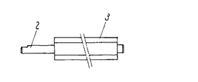
従来の技術を図12〜図14により説明する。図12は一般的な磁気ブラシ現像装置を示す。1はアルミニウム、またはステンレス製のスリーブで、シャフト2によりマグネットロールの外周を回転自在となっている。マグネットロールは複数の扇状の磁場成形ピース3を円柱状に組合わせて形成する。図13は図12のスリーブ1内のマグネットロールを示す。図14は従来の着磁ヘッドとマグネットロールの断面図を示す。4は着磁装置、5は着磁ヘッド、6は着磁ヘッド5の配線を示す。図12においてN1は現像極、S3は回収・剥離極、S2は汲み上げ極、N2・S1は搬送極を示す。現像プロセスにおいて、図12に示す非磁性材からなるスリーブ1が回転することで、汲み上げ極S2によって引き付けられた現像剤がスリーブ1表面上を搬送され感光ドラム10に供給される。現像点通過後の現像剤は回収され回収・剥離極S3〜汲み上げ極S2間で剥離し、次の汲み上げ極S2で新たな現像剤を汲み上げるといった工程で搬送し、現像プロセスを構成している。
【0003】
従来は、図14のように5個の磁場成形ピース3の各極ごとに着磁ヘッド5を配置し、配線6への電流調整にてマグネットロールに磁界を与えている。
【0004】
【発明が解決しようとする課題】
しかしながら、上記構成において、マグネットの特質上同極の磁気波形が隣接する部分、具体的には回収・剥離極S3〜汲み上げ極S2部では磁気波形が不安定であり、現像剤が剥離せずつれ回りし、画質濃度が低下するなどの原因になっていた。
【0005】
本発明は、上記従来技術における欠点を解決し、より高性能の磁気ブラシ現像用マグネットロールの着磁装置を提供することを目的とするものである。
【0006】
【課題を解決するための手段】
上記課題を解決するために本発明は、複数の扇状の磁場成形ピースで構成したマグネットロールにおいて、同極磁気波形が隣接する部分の磁場成形ピースに切欠部を設けるとともに、前記切欠部を2つの磁場成形ピースにまたがるように設け、前記切欠部と対向する位置に着磁ヘッドを配置することを特徴とするものであり、これにより、磁気波形の谷部分の波形をコントロールするものである。
【0007】
【発明の実施の形態】
本発明の請求項1に記載の発明は、シャフトの周囲に扇状のピースを複数個取付けて構成したマグネットロールにおいて、同極磁気波形が隣接する部分の磁場成形ピースに切欠部を設けるとともに、前記切欠部を2つの磁場成形ピースにまたがるように設け、前記切 欠部と対向する位置に着磁ヘッドを配置することを特徴とするマグネットロールの着磁装置であり、そのことにより、現像剤の回収・剥離及び汲み上げ部分の磁力をコントロールし現像剤の搬送を均一にし画質を向上させるものである。
【0008】
以下本発明の一実施形態について、図1〜図11を参照しながら説明する。なお、図12〜図14と同一部分には同一番号を付しており、これにより説明を簡略化する。また図1〜図8、図12、図14は断面図であるが、繁雑をさけるためハッチングは省略している。
【0009】
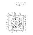
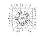
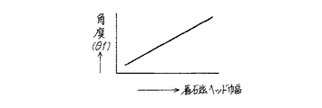
図1は本発明の第1例の着磁装置とマグネットロールの断面図を示し、5は磁極着磁用の着磁ヘッド、6は着磁ヘッド5の配線、7は同極波形間用の着磁ヘッドを示し、同極である回収・剥離極S3と汲み上げ極S2間の磁場成形ピース3,3どうしの接合部分の外周に着磁ヘッド7を当接させたものであり、これによりこの部分の着磁波形8を破線から実線のごとく低下させ、前回の現像剤をスリーブ1から落下させやすくしている。図2は本発明の第2例の着磁装置とマグネットロールの断面図を示し、この例では図1の着磁ヘッド7に配線6を巻き付けることによりこの部分の着磁波形8をさらに低下させるものであり、前回の現像剤はスリーブ1からさらに落下しやすくなる。図3は本発明の第3例を示し、着磁ヘッド7の幅を狭くしたものを示す。図4は本発明の第4例を示し、着磁装置の着磁ヘッド7の高さを低くして、磁場成形ピース3から離したものである。図5は本発明の第5例を示し、着磁装置の着磁ヘッド7の位置を汲み上げ極S2側にずらしたものである。図6は本発明の第6例を示し、着磁装置の着磁ヘッド7に対応する磁場成形ピース3に切欠部付き3aを設けたものである。本発明では、各扇状の磁場成形ピース3をシャフト2の外周に貼り付け円柱形を構成するマグネットロールにおいて、図1〜図6のように同極の磁気波形が隣接する部分の間に着磁ヘッド7を配置することによって、図7に示されるような着磁波形8で表れる波形のθ1,θ2角度及び磁力のθ3をコントロールするものである。なお同極以外の磁気波形が隣接する場合においても、図8に示されるような磁界で表される波形のθ4角度及び磁力のθ5をコントロールすることができる。なお図7、図8の9は磁束密度0Gポイントを示す。また図9は、磁気波形角度(θ1)の変化推移グラフ、図10は磁気波形角度(θ2,θ4)の変化推移グラフ、図11は磁気波形磁力(θ3,θ5)の変化推移グラフである。
【0010】
【発明の効果】
以上のように本発明は、シャフトの周囲に扇状のピースを複数個取付けて構成したマグネットロールにおいて、同極磁気波形が隣接する部分の磁場成形ピースに切欠部を設けるとともに、前記切欠部を2つの磁場成形ピースにまたがるように設け、前記切欠部と対向する位置に着磁ヘッドを配置することで、画質向上を図ることのできる着磁を行うことができる。
【図面の簡単な説明】
【図1】 本発明の第1例の着磁装置とマグネットロールの断面図
【図2】 本発明の第2例の着磁装置とマグネットロールの断面図
【図3】 本発明の第3例の着磁装置とマグネットロールの断面図
【図4】 本発明の第4例の着磁装置とマグネットロールの断面図
【図5】 本発明の第5例の着磁装置とマグネットロールの断面図
【図6】 本発明の第6例の着磁装置とマグネットロールの断面図
【図7】 磁気波形の概念図
【図8】 磁気波形の概念図
【図9】 磁気波形角度(θ1)の変化推移グラフ
【図10】 磁気波形角度(θ2,θ4)の変化推移グラフ
【図11】 磁気波形磁力(θ3,θ5)の変化推移グラフ
【図12】 磁気ブラシ現像装置の断面図
【図13】 マグネットロールの正面図
【図14】 従来の着磁装置とマグネットロールの断面図
【符号の説明】
1 スリーブ
2 シャフト
3 磁場成形ピース
4 着磁装置
5 着磁ヘッド(磁極着磁用)
6 着磁ヘッドの配線
7 着磁ヘッド(同極間波形用)
8 着磁波形
9 磁束密度0Gポイント[0001]
BACKGROUND OF THE INVENTION
The present invention relates to a magnetizing device for a magnetic roll for developing a magnetic brush used in an electrophotographic copying machine, a printer or a facsimile machine.
[0002]
[Prior art]
Conventional techniques will be described with reference to FIGS. FIG. 12 shows a general magnetic brush developing device.
[0003]
Conventionally, as shown in FIG. 14, a
[0004]
[Problems to be solved by the invention]
However, in the above configuration, due to the nature of the magnet, the magnetic waveform is unstable in the portion where the magnetic waveform of the same polarity is adjacent, specifically, the recovery / separation pole S3 to the pumping pole S2, and the developer is peeled off each time. It turned around, causing the image quality density to decrease.
[0005]
SUMMARY OF THE INVENTION An object of the present invention is to solve the above-mentioned drawbacks of the prior art and to provide a magnet roller magnetizing apparatus for developing a magnetic brush with higher performance.
[0006]
[Means for Solving the Problems]
In order to solve the above-mentioned problems, the present invention provides a magnet roll composed of a plurality of fan-shaped magnetic field shaping pieces . The magnetic head is provided so as to straddle the magnetic field shaping piece, and the magnetizing head is arranged at a position facing the notch, thereby controlling the waveform of the valley portion of the magnetic waveform.
[0007]
DETAILED DESCRIPTION OF THE INVENTION
The invention according to
[0008]
Hereinafter, an embodiment of the present invention will be described with reference to FIGS. In addition, the same number is attached | subjected to the same part as FIGS. 12-14, and description is simplified by this. 1-8, 12 and 14 are cross-sectional views, but hatching is omitted to avoid complication.
[0009]
FIG. 1 is a cross-sectional view of a magnetizing apparatus and a magnet roll according to a first example of the present invention, wherein 5 is a magnetizing head for magnetic pole magnetization, 6 is a wiring of the magnetizing
[0010]
【The invention's effect】
As described above, according to the present invention , in a magnet roll configured by mounting a plurality of fan-shaped pieces around a shaft, a notched portion is provided in a magnetic field forming piece at a portion where homopolar magnetic waveforms are adjacent to each other, and the notched portion is provided with 2 notches. Magnetization capable of improving the image quality can be performed by providing the magnetic field molding pieces so as to extend over the two magnetic field shaping pieces and disposing the magnetizing head at a position facing the notch .
[Brief description of the drawings]
FIG. 1 is a cross-sectional view of a magnetizing apparatus and a magnet roll according to a first example of the present invention. FIG. 2 is a cross-sectional view of a magnetizing apparatus and a magnet roll according to a second example of the present invention. FIG. 4 is a sectional view of a magnetizing device and a magnet roll of a fourth example of the present invention. FIG. 5 is a sectional view of a magnetizing device of the fifth example of the present invention and a magnet roll. 6 is a sectional view of a magnetizing apparatus and a magnet roll according to a sixth example of the present invention. FIG. 7 is a conceptual diagram of a magnetic waveform. FIG. 8 is a conceptual diagram of a magnetic waveform. FIG. 9 is a change in a magnetic waveform angle (θ1). Transition graph [FIG. 10] Change transition graph of magnetic waveform angle (θ2, θ4) [FIG. 11] Change transition graph of magnetic waveform magnetic force (θ3, θ5) [FIG. 12] Cross-sectional view of magnetic brush developing device [FIG. 13] Magnet Front view of roll [Fig.14] Breaking of conventional magnetizer and magnet roll Figure [Description of the code]
DESCRIPTION OF
6 Wiring of
8 Magnetization waveform 9 Magnetic flux density 0G point
Claims (1)
Priority Applications (1)
| Application Number | Priority Date | Filing Date | Title |
|---|---|---|---|
| JP20714499A JP3674397B2 (en) | 1999-07-22 | 1999-07-22 | Magnet Roller Magnetizing Device for Magnetic Brush Development |
Applications Claiming Priority (1)
| Application Number | Priority Date | Filing Date | Title |
|---|---|---|---|
| JP20714499A JP3674397B2 (en) | 1999-07-22 | 1999-07-22 | Magnet Roller Magnetizing Device for Magnetic Brush Development |
Publications (2)
| Publication Number | Publication Date |
|---|---|
| JP2001034069A JP2001034069A (en) | 2001-02-09 |
| JP3674397B2 true JP3674397B2 (en) | 2005-07-20 |
Family
ID=16534946
Family Applications (1)
| Application Number | Title | Priority Date | Filing Date |
|---|---|---|---|
| JP20714499A Expired - Lifetime JP3674397B2 (en) | 1999-07-22 | 1999-07-22 | Magnet Roller Magnetizing Device for Magnetic Brush Development |
Country Status (1)
| Country | Link |
|---|---|
| JP (1) | JP3674397B2 (en) |
Families Citing this family (2)
| Publication number | Priority date | Publication date | Assignee | Title |
|---|---|---|---|---|
| JP4506944B2 (en) * | 2003-12-25 | 2010-07-21 | Tdk株式会社 | Magnet roll magnetizing method and apparatus |
| JP5423351B2 (en) * | 2009-11-25 | 2014-02-19 | 富士ゼロックス株式会社 | Magnet roll magnetizing device and magnet roll manufacturing method |
-
1999
- 1999-07-22 JP JP20714499A patent/JP3674397B2/en not_active Expired - Lifetime
Also Published As
| Publication number | Publication date |
|---|---|
| JP2001034069A (en) | 2001-02-09 |
Similar Documents
| Publication | Publication Date | Title |
|---|---|---|
| JP3468849B2 (en) | Developing device | |
| JP3674397B2 (en) | Magnet Roller Magnetizing Device for Magnetic Brush Development | |
| JP2001034068A (en) | Magnet roll for magnetic brush development | |
| JPH0145634B2 (en) | ||
| JP3109314B2 (en) | Magnet roll and manufacturing method thereof | |
| JP2861681B2 (en) | Image forming device | |
| EP0209159B1 (en) | Electrostatic recording apparatus and recording electrode therefor | |
| JP2711507B2 (en) | Developing device | |
| JPH0738925Y2 (en) | Cleaning Magnet Roll for Electrophotographic Equipment | |
| JP3438428B2 (en) | Magnet roll | |
| JPH08254900A (en) | Developing device | |
| JP2523929Y2 (en) | Developing device | |
| JP2011141355A (en) | Developer-collecting device, developing device, process cartridge, and image-forming device | |
| JPS59131957A (en) | Magnetic brush developing device | |
| JP2005195974A (en) | Magnet roll and developing apparatus | |
| JP2002341657A (en) | Two-component developing device | |
| JPH02196669A (en) | Electrostatic recorder | |
| JPH10123824A (en) | Developing unit | |
| JPH04338781A (en) | Developing device | |
| JPS60250377A (en) | electrophotographic copying device | |
| JPS61162072A (en) | Developing device | |
| JPH0792811A (en) | Developing device and image forming apparatus including the developing device | |
| JPS645301B2 (en) | ||
| JPS587670A (en) | Magnetic brush developing device | |
| JPS59196268A (en) | Recording apparatus |
Legal Events
| Date | Code | Title | Description |
|---|---|---|---|
| A977 | Report on retrieval |
Free format text: JAPANESE INTERMEDIATE CODE: A971007 Effective date: 20041124 |
|
| A131 | Notification of reasons for refusal |
Free format text: JAPANESE INTERMEDIATE CODE: A131 Effective date: 20041130 |
|
| A521 | Written amendment |
Free format text: JAPANESE INTERMEDIATE CODE: A523 Effective date: 20050131 |
|
| TRDD | Decision of grant or rejection written | ||
| A01 | Written decision to grant a patent or to grant a registration (utility model) |
Free format text: JAPANESE INTERMEDIATE CODE: A01 Effective date: 20050405 |
|
| A61 | First payment of annual fees (during grant procedure) |
Free format text: JAPANESE INTERMEDIATE CODE: A61 Effective date: 20050418 |
|
| R151 | Written notification of patent or utility model registration |
Ref document number: 3674397 Country of ref document: JP Free format text: JAPANESE INTERMEDIATE CODE: R151 |
|
| FPAY | Renewal fee payment (event date is renewal date of database) |
Free format text: PAYMENT UNTIL: 20090513 Year of fee payment: 4 |
|
| FPAY | Renewal fee payment (event date is renewal date of database) |
Free format text: PAYMENT UNTIL: 20100513 Year of fee payment: 5 |
|
| FPAY | Renewal fee payment (event date is renewal date of database) |
Free format text: PAYMENT UNTIL: 20110513 Year of fee payment: 6 |
|
| FPAY | Renewal fee payment (event date is renewal date of database) |
Free format text: PAYMENT UNTIL: 20110513 Year of fee payment: 6 |
|
| FPAY | Renewal fee payment (event date is renewal date of database) |
Free format text: PAYMENT UNTIL: 20120513 Year of fee payment: 7 |
|
| FPAY | Renewal fee payment (event date is renewal date of database) |
Free format text: PAYMENT UNTIL: 20120513 Year of fee payment: 7 |
|
| FPAY | Renewal fee payment (event date is renewal date of database) |
Free format text: PAYMENT UNTIL: 20130513 Year of fee payment: 8 |
|
| FPAY | Renewal fee payment (event date is renewal date of database) |
Free format text: PAYMENT UNTIL: 20130513 Year of fee payment: 8 |
|
| EXPY | Cancellation because of completion of term |